1. Introduction
Wireless power transmission has become more extensively employed for its advantages (e.g., safety and convenience) over the past few years. Magnetic coupling resonant wireless power transmission uses the principle of electromagnetic induction to transmit power from the grid end to the mobile end [
1,
2,
3]. Compared with conventional contact charging, this charging method is safer, more reliable, more flexible, and more conducive to maintenance. Magnetic induction coupling wireless power transmission displays a certain gap between the two coils, the main magnetic circuit exhibits a significant reluctance, and the system requires considerable reactive power, such that the capacity of the device and the loss of the system will be increased. As a result, the efficiency of the system will be reduced. To avoid the above-mentioned hazard, a compensation network is generally introduced to the primary and secondary terminals of the magnetically coupled resonant wireless power transfer system to optimize the power factor and reduce the ability of the switching device to withstand current.
Scholars have conducted considerable research in terms of the compensation network of the wireless power transfer system. A growing amount of research on the high-order compensation network has been conducted due to the significant shortcomings of the four basic compensation networks. The LCC compensation network exhibits significant advantages. Scholars have conducted preliminary research. In the literature [
4,
5,
6], the double LCC compensation network was studied. As indicated by the result, the output of the wireless power transfer system is characterized by a constant-current source at the natural resonant frequency, which makes it easy to achieve constant-current output control and is not affected by load changes, whereas it cannot achieve constant current. Voltage control hinders constant-voltage charging of battery loads. The paper [
7] investigated the requirement of constant-current and then constant-voltage charging of lithium batteries. In addition, research was conducted on the compensation network, and an LCC-S/P compensation structure was proposed. The transmitter employs LCC compensation, and the receiver adopts a combination of series compensation and parallel compensation. Nevertheless, the receiving-end compensation topology should be switched to achieve the system’s constant-current or constant-voltage output, such that the complexity of the system circuit and its control can be increased. Articles [
8,
9] conducted an optimization study on the LCC-S compensation network, considering the system optimization under three different coupling levels of high, medium, and low, such that the system exhibits better dynamic adaptability in the process of wireless power transmission and certain anti-offset abilities. Articles [
10,
11,
12] compared the SS and double LCC compensation topologies. In comparison with the SS compensation structure, under identical output power, the output efficiency of the wireless power transfer system with double LCC compensation is significantly higher than that of SS compensation. In the above literature, the output characteristics of the LCC compensation network at the natural resonant frequency are analyzed without considering the offset between the receiving end and the transmitting end or the effect on the output characteristics of the wireless power transfer system when the resonant frequency does not match the coupling coefficient. In the research on the anti-migration of underwater wireless charging, the literature mainly focuses on the design of coupling mechanisms, and the research on compensation networks is relatively rare. Reference [
13] employed SS compensation topology for research. The system’s anti-offset capability is improved by optimizing the parameters of the series capacitor, whereas the low-order compensation network is adopted to enhance the transmission performance of the system. Literature [
14] realizes the maximum transmission efficiency and transmission power of the system by optimizing the coil structure and putting different coils into work according to the different load resistances, aiming to improve the stability of the system in the coupling mechanism, but the coupling mechanism design is complicated and the cost is high. In the literature [
15,
16,
17,
18], constant-voltage and constant-current output of the system are realized by using multiple resonant points through series or parallel capacitors. However, no excessive research has been conducted on the anti-migration part. However, large voltage fluctuations may occur during the switching process, which will affect the stability of the system. In the literature [
19,
20], the constant-current output characteristics were achieved using a double LCL compensation network, and the effect of the offset of the receiving and transmitting coils on the output performance of the system was investigated. With the increase in offset, the coupling coefficient declines, and the transmission capacity of the system tends to be reduced. There is no effective solution to this problem.
To solve the problem that the coupling coefficient decreases with the increase in the coil offset in the wireless power transfer system, such that the power transmission capacity can be reduced. In this study, the impedance characteristics of the double LCC compensation network are investigated. Under constant-current output, the system covers at least three resonance points that are independent of the load impedance. Additionally, under constant-voltage output, the system comprises at least two resonance points that are independent of the load impedance point. The proposed solution in this paper achieves the constant-voltage and constant-current characteristics of the system and improves the power transmission capacity of the system without adding additional inductor capacitors. The disadvantage is that more inductors and capacitors are still used compared with the basic compensation network, which increases the design difficulty and increases the cost to a certain extent. Because the power transmission capacity of the system at a certain resonance point increases with the increase in the coupling coefficient, the other resonance point is more suitable for power transmission at a low coupling coefficient. Using the method of switching between multiple resonance points, the system is capable of achieving constant-voltage and constant-current output and complying with the appropriate resonance frequency based on different coupling coefficients. On that basis, the power and efficiency of wireless power transmission in the system can be effectively improved, and a smaller current distortion rate can be obtained. Accordingly, the system exhibits better anti-offset capability.
2. Basic Principles of Magnetic Coupling Resonance Wireless Power Transmission
Magnetic coupling resonance wireless power transmission (MCR-WPT) conforms to the principles of electromagnetic induction and coupling to realize power transmission.
Figure 1 presents a block diagram of wireless power transmission [
21,
22,
23,
24].
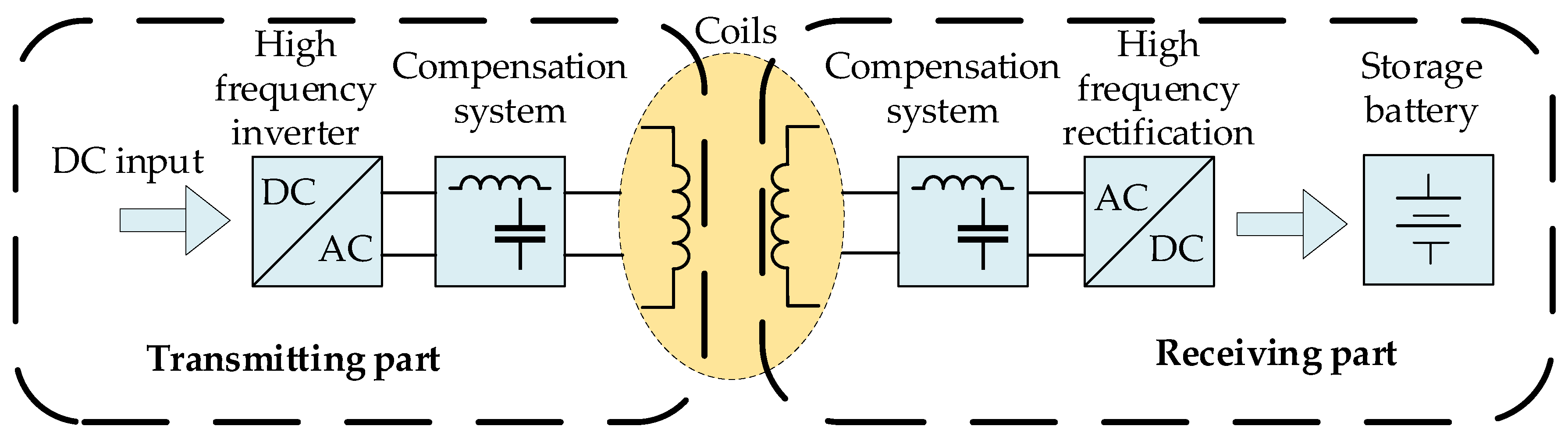
Underwater wireless power transmission can be widely used in autonomous underwater vehicles (AUVs) and robots and can also provide reliable energy supply for ocean observation and monitoring systems. A typical magnetic coupling resonant underwater wireless power transfer system comprises four parts: a high-frequency inverter circuit, a coupling mechanism, a compensation network, and a high-frequency rectifier circuit [
25,
26,
27,
28]. The transmitting end is provided with DC input by the underwater cable or the mother ship. Subsequently, the input DC power is converted into high-frequency AC power through the high-frequency inverter circuit to provide energy for the primary side of the coupling mechanism. In accordance with the principle of electromagnetic induction, the secondary side of the coupling mechanism receives the energy emitted by the primary side, and the receiving end rectifies the received high-frequency alternating current into direct current through a high-frequency rectification circuit, and after filtering, it becomes the power of the AUV. Furthermore, batteries provide energy.
Underwater wireless power transmission needs to achieve energy transmission in the underwater environment. The properties of water can impact the transmission of electromagnetic waves and result in energy loss. The dielectric constant of water is higher than that of air or vacuum, leading to even more energy loss. Additionally, the transparency and depth of the water can affect the effectiveness of underwater wireless power transmission. Water transparency affects the penetration ability of electromagnetic waves, while depth increases the distance of signal transmission and reduces signal strength. The change in water depth and transparency will eventually be reflected in the change in coupling coefficient, which will affect the power transmission ability of the system. When there is an offset between the receiving and transmitting coils, the power transmission of the underwater wireless power transfer system can be greatly affected. This issue needs to be addressed through resonance compensation.
The resonance compensation circuit of the MCR-WPT system typically consists of capacitors and inductors. Because of the large leakage inductance in the loosely coupled mechanism, the resonance compensation system is mainly used to compensate for the high reactive power required by the coil. The compensation network is generally used on both the primary and secondary sides. The low-order compensation network includes four types: series–series (S–S) compensation, series–parallel (S–P) compensation, parallel–series (P–S) compensation, and parallel–parallel (P–P) compensation. High-order compensation networks include LCL-S, LCL-P, double LCL, double LCC, and other compensation methods.
While the low-order compensation network is relatively simple in design and generates a small resonant current, it is required to deliver a large amount of power during startup, necessitating high stability of the resonant circuit and making it extremely sensitive to variations in the position of the coils. Any changes in position can result in a reduction in charging efficiency. On the other hand, high-order resonance compensation technology can integrate additional inductance and capacitance components into the resonant circuit, optimizing its performance, minimizing power loss and energy leakage, and improving charging efficiency while also reducing the circuit’s sensitivity to distance changes. This can improve the stability and efficiency of charging. Furthermore, the high-order resonance compensation network is highly adaptable and can be easily adjusted and upgraded as required, exhibiting excellent scalability and adaptability.
Existing research has demonstrated that the double LCC resonant compensation network possesses multiple resonant frequencies. In comparison to the fundamental resonant compensation network, it possesses the attributes of a constant-voltage and constant-current source, as well as no-load protection characteristics. By switching the power transmission frequency, the system can be transitioned to a different resonance state, thereby offering an effective method to improve transmission power and efficiency. This study presents a detailed mathematical model of the double LCC compensation topology derived from the mutual inductance coupling model. It proposes matching the appropriate resonance frequency to various coupling intervals to enhance the transmission power and efficiency of underwater wireless power transfer systems.
3. Impedance Analysis of Double LCC Resonant Compensation Network
3.1. Secondary-Side LCC Network Impedance
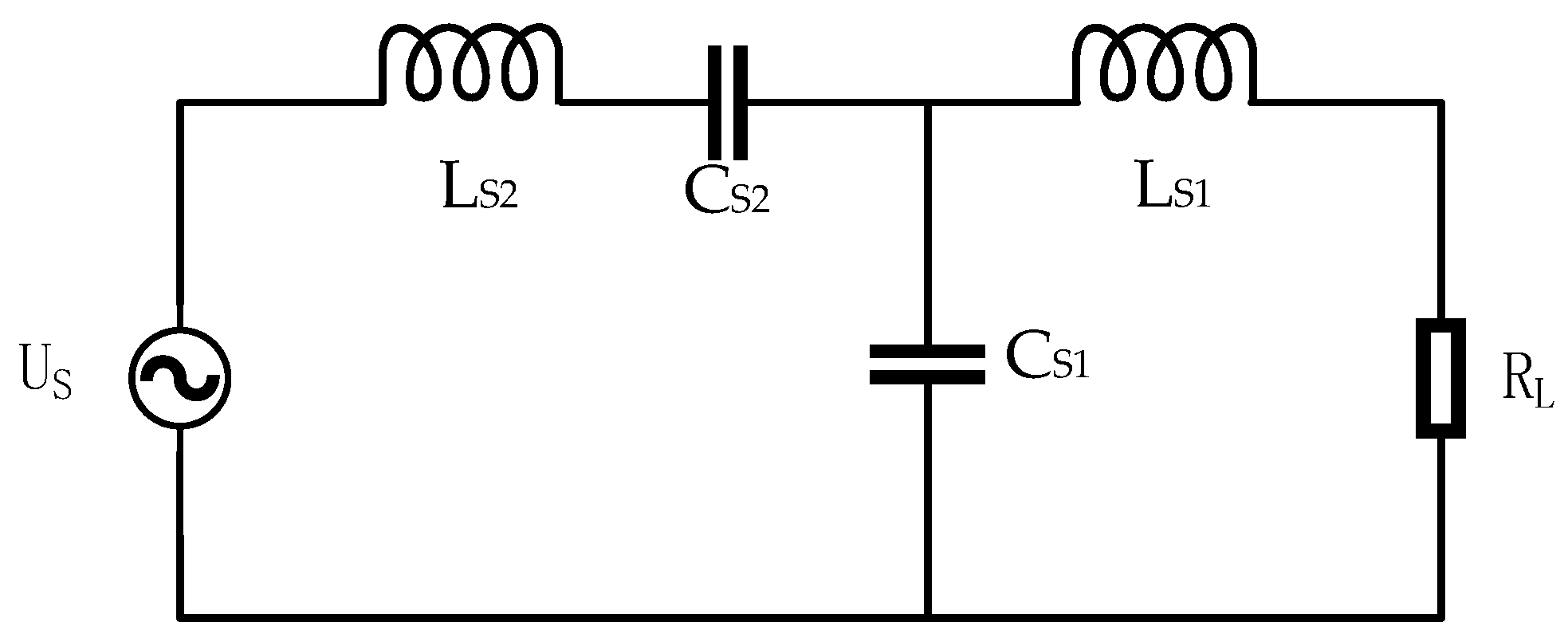
Figure 2 presents the topology circuit of the secondary-side LCC resonance compensation network. To simplify the analysis, the parasitic internal resistance of the components is not considered in the secondary-side power transmission circuit. As depicted in the figure, the expression of the input impedance Z
S of the secondary-side LCC network of underwater wireless power transmission can be obtained as follows:
In the equation , ω = 2πf is the angular frequency of the input voltage, CS1 and CS2 are the compensating capacitors of the LCC compensation network, LS1 and LS2 are the two inductors of the LCC compensation network, and RL is the load resistance.
The real and imaginary parts of the input impedance can be expressed as:
When the reactive power flows through the inverter bridge, it leads to additional losses. Therefore, in order to achieve a purely resistive LCC compensation network, i.e., to make its imaginary part zero, a constraint condition must be satisfied. Through calculations, an inherent resonant frequency point
ω0 is obtained, and two sub-resonant frequencies
ω1 and
ω2, which are related to the load
RL, are shown in Formula (4). When the condition is satisfied
, the imaginary part of the input impedance of the system is much smaller than the real part, and the expression can accurately describe the resonant frequency. Therefore, appropriate parameters should be selected according to the load during design.
By substituting
ω0,
ω1, and
ω2 into Equation (1), we can obtain the input impedance of the LCC compensation network at each of the three resonant frequencies when the system operates at these frequencies.
The Formula (4) indicates that when the system operates at ω0, the input impedance is related to the inductance and capacitance values of the LCC compensation network, as well as the load impedance value. When the system operates at ω1 and ω2, the input impedance is related to the load impedance and the compensation capacitance value and is independent of other parameters.
When the resonant frequency is
ω0, the output current is shown in formula (6), and the magnitude of the output current is independent of the load. The LCC network exhibits a constant-current output characteristic, and the load current is given by:
When the resonant frequency is
ω1,
ω2, the LCC compensation network can exhibit the characteristics of constant-voltage output at this time; the output voltage has nothing to do with the load, and the load voltage is:
3.2. Primary-Side LCC Network Impedance
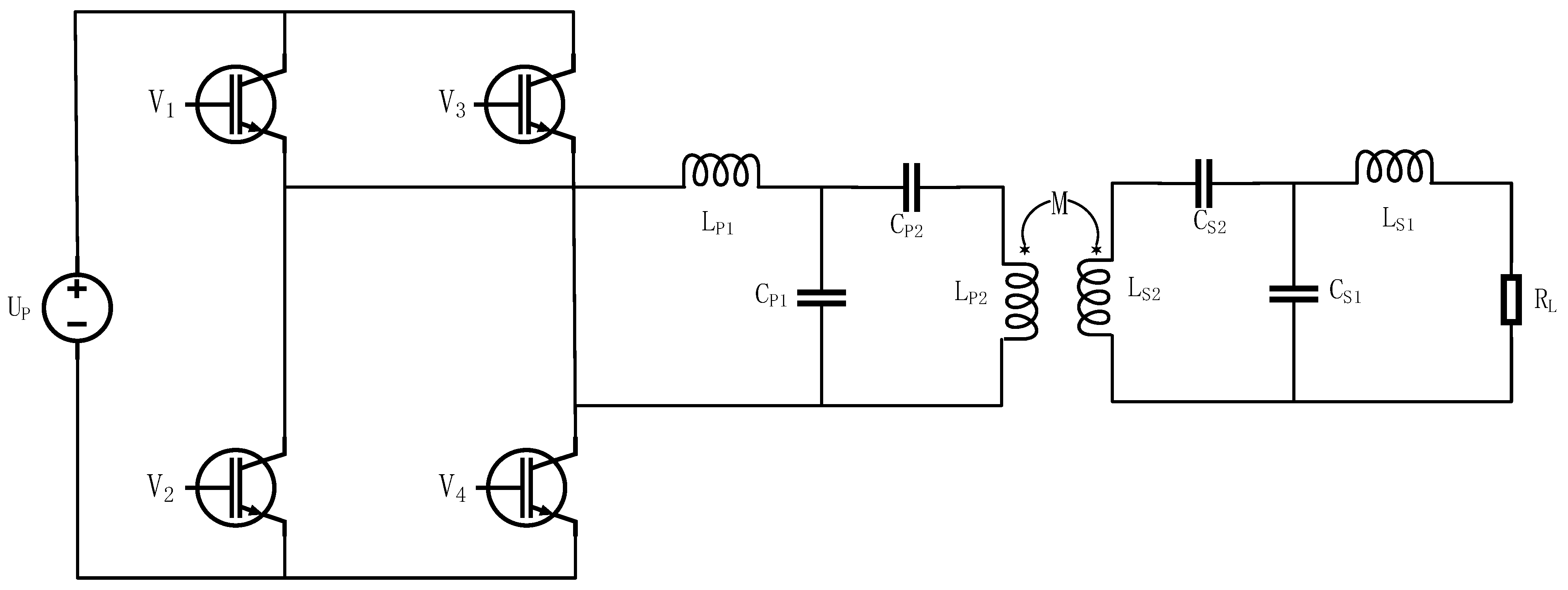
Figure 3 presents an underwater wireless power transfer system based on a double LCC resonant compensation network. The transmitting coil and receiving coil are equivalent to a mutual inductance model, where L
P1 denotes the primary-side compensation inductance, C
P1 and C
P2 represent the primary-side compensation capacitors, L
S1 is the secondary-side compensation inductance, and C
S1 and C
S2 express the secondary-side compensation capacitors. To simplify the calculation process, the internal resistance r of the primary-side DC power supply is ignored, and the parasitic resistance r
P1, r
P2 of the coils
LP1,
LP2 is ignored. The units of all components in the formula are international units, i.e., the units of inductance are H, capacitance is F, and resistance is Ω. The physical meaning of Z
ref is that the secondary-side loop acts on the primary side, i.e., the equivalent impedance of the circuit. To calculate the loop impedance of the dual LCC resonant compensation network at the input end, and analyze the resonant frequency and power transfer characteristics of the compensation network, Equation (8) is first defined, and
λP represents the ratio of the values of the primary compensation capacitors
CP1 and
CP2 of the system, which is adopted in this study to analyze the effect of
λP,
λS on the resonant frequency, transmission power, and coupling coefficient of the double LCC resonant compensation network. The expression (9) of the total input impedance of the primary loop of the system is illustrated as follows:
When the system is in a resonant state, the input impedance exhibits purely resistive behavior, that is, the imaginary part of the input impedance Z
in is zero. The resonant points of the double LCC resonant compensation network are obtained. The multiple resonant points generally include a stable inherent resonant frequency and several sub-stable resonant frequencies. In a double-sided LCC resonant compensation system, the inherent resonant frequency is not affected by the load, and the output end exhibits a current source output characteristic. However, the sub-stable resonant frequency points will change with the load variation, but as long as the imaginary part of the system input impedance is much smaller than the real part, we can assume that the sub-stable resonant frequency points are not affected by the load. This article first analyzes the output characteristics of the double LCC resonant compensation system at the inherent resonant point, and then extends the analysis to the output characteristics of other sub-harmonic frequency points in the system. The expression for the imaginary part of the input impedance Z
in is shown in Equation (11).
According to the analysis of Equation (11), a natural resonant frequency point
ωP0 that does not vary with the load can be obtained under the condition of satisfying Equation (12). Substituting Equation (12) into Equation (11) and setting it equal to zero yields the resonant frequency points of the double LCC resonant compensation system, as shown in Equation (13). Through analysis, when
ωP1 and
ωP2 satisfy Equation (14), it can be considered that the imaginary part of the system is much smaller than the real part, and therefore, the two resonant frequency points
ωP1 and
ωP2 do not vary with the load and can be regarded as two sub-stable resonant frequency points.
Substituting Equation (12) into Equation (9) yields the expression of the input impedance at the natural and sub-resonant frequencies, as shown in Equation (15). Further calculation of the output voltage and output current of the dual LCC resonance compensation system shows that the system exhibits parallel resonance characteristics at the resonant frequency
ωP0, with the output presenting the characteristics of a current source, as shown in Equation (16), and series resonance characteristics at
ωP1 and
ωP2, with the output presenting the characteristics of a voltage source, as shown in Equation (17).
From the above analysis, it can be concluded that the dual-sided LCC compensation network has multiple resonance points that are independent of load impedance. In the past, single resonance point designs were often used for wireless power transfer, which greatly limited the flexibility of power transmission. If multiple resonance points and the characteristics of energy output are matched, it will effectively improve the transmission power and efficiency of wireless power transfer systems.
4. Analysis of Constant Voltage Output Characteristics of Multi-Resonance Point Switching
The conventional charging process of the battery is mainly three-stage, followed by three stages of constant-current charging, constant-voltage charging, and floating charging. In the underwater wireless power transfer system, the system generally falls into two parts, i.e., wireless transmission and DC/DC converter, due to the difficulty of information exchange between the transmitter and the receiver. The DC/DC converter is responsible for the three-stage charging function of the battery, and the wireless transmission part is designed with a constant-voltage output characteristic. In the following, the focus is placed on the analysis of the constant-voltage output system with multi-resonance point switching.
Matching the resonant frequencies with different characteristics, we can set
ωP1 =
ωS0 =
ω1 and
ωP0 =
ωS2 =
ω2, and the frequency relationships correspond as follows:
Based on Equation (18), the constraint relationship between
λP and
λS can be obtained as shown in Equation (19):
The reflection impedances from the secondary side to the primary side at the two resonant frequencies are shown in Equations (20) and (21), respectively.
The reflected impedance from the secondary to the primary side at the two resonant frequencies can be expressed as Equations (20) and (21), respectively, where k is the coupling coefficient. In the case of a given coil structure, magnetic core structure, and magnetic material, the coupling coefficient k is only related to the spatial position of the coils. As the positions of the receiving and transmitting coils change, the coupling coefficient also changes. The larger the displacement, the lower the coupling coefficient, and this variation in the coupling coefficient can cause changes in the characteristics of power transfer.
The output voltage at the two resonant frequencies can be calculated according to Equations (22) and (23), respectively.
The output power at the two resonant frequencies is shown in Equations (24) and (25), respectively:
From Equation (23), it can be seen that when using ω2 for wireless power transfer, as the offset increases, the coupling coefficient k gradually decreases, causing a decrease in the system output voltage and a decrease in the quality of wireless power transfer. If, after the offset, the wireless power transfer is switched to ω1, as shown in Equation (22), the coupling coefficient decreases and the system output voltage increases, ensuring the wireless power transfer capability of the system. Therefore, using a multi-resonant point switching method for wireless power transfer can make the system have better resistance to offset.
When charging the battery in an underwater wireless power transfer system, large power fluctuations should be avoided, especially when switching resonance frequency points. To achieve this, an appropriate multi-resonance point switching strategy should be adopted. According to Formulas (24) and (25), the output power is not only related to the resonance frequency but also to the coupling coefficient. The output power under the resonance frequency ω1 decreases with the decrease in the coupling coefficient, while the output power under the resonance frequency ω2 increases with the decrease in the coupling coefficient. Therefore, by finding the coupling coefficient kc that corresponds to equal power, frequency switching can be performed at kc to keep the transmission power constant.
Under the constraint condition given by Equation (19), the coupling coefficient during frequency switching can be calculated as shown in Equation (26):
5. Simulation Analysis
Firstly, the coupling mechanism model is established in ANSYS/Maxwell; the transmitter and receiver coil structure is circular; the transmitter coil has 20 turns; the receiver coil has 16 turns; the inner diameter is 85 mm; the receiver and transmitter coils are equipped with square ferrite; the volume of the transmitter ferrite is 400 mm × 400 mm × 5 mm; and the volume of the receiver ferrite is 300 mm × 300 mm × 5 mm. Then the boundary conditions are established, the environment is set to seawater, and the finite element simulation is carried out to obtain the parameters of self-inductance, mutual inductance, and coupling coefficient of the transmitter and receiver coils. Under the initial position of alignment, the offset simulation experiments of offset 0–30 cm in the XYZ axis direction are studied, respectively, and the relationship curves between the coupling mechanism at different positions and the coupling coefficient are derived. The mutual inductance coupling model is used in MATLAB, combined with the results calculated by Maxwell; the self-inductance of the transmitting and receiving coils is set; the corresponding coupling coefficients are set under different positions; and the bilateral LCC compensation network is used to build the simulation circuit in MATLAB/SIMULINK for simulation. The relevant parameters of the simulation have been listed in
Table 1.
The parameters of the selected double LCC resonance compensation system were obtained through the above analysis, as listed in
Table 1. Substituting
λP and
λS in
Table 1 into Equation (26), the coupling coefficient at the time of frequency switching can be obtained as 0.4. When
k > 0.4,
ω2 is employed for underwater wireless power transfer system transmission. When
k < 0.4,
ω1 is adopted for underwater wireless power transfer system transmission. Frequency switching is capable of effectively ensuring the stability of system transmission power when
k = 0.4.
5.1. Multiple Resonance Point Simulation
Simulation analysis of multiple resonance points of the double LCC resonant compensation system was conducted in Matlab.
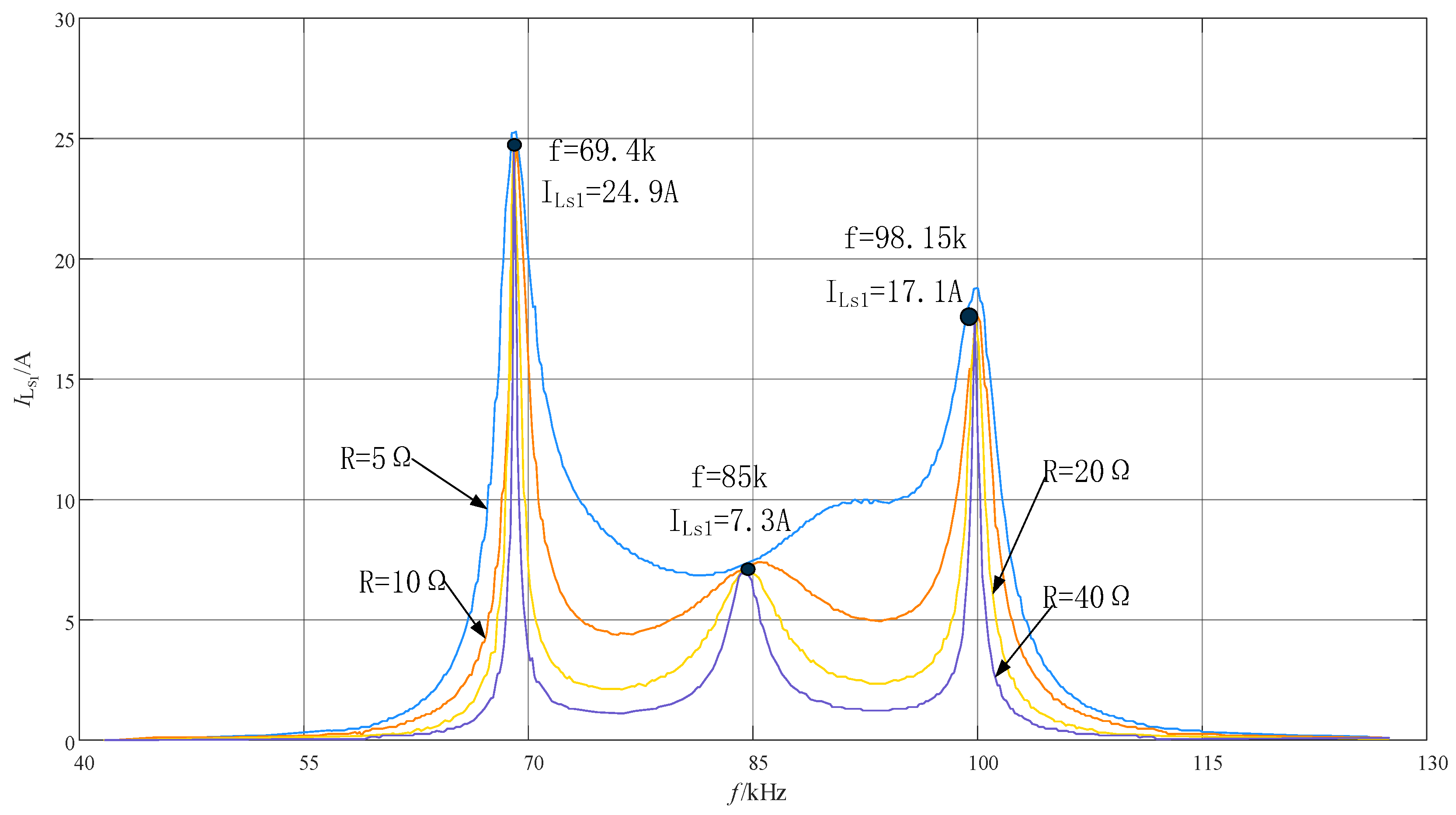
Figure 4 shows the relationship curve between the output current and operating frequency under different load R
L. The system has multiple constant-current resonance points, with output currents of 24.9 A, 7.3 A, and 17.1 A at 69.4 kHz, 85 kHz, and 98.15 kHz, respectively. The system exhibits load-independent constant-current output characteristics. It was verified that all three resonant frequencies were in resonance and exhibited pure resistive characteristics.
Under different load R
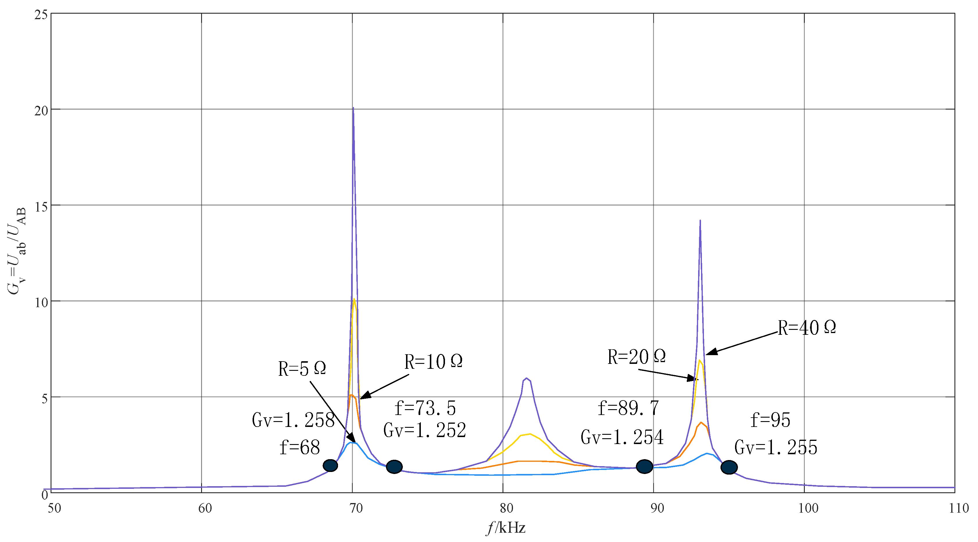
L conditions, the system frequency was scanned from 30 kHz to 110 kHz, and multiple constant-voltage resonant points were found.
Figure 5 shows the relationship between the input–output voltage gain and the operating frequency of the system under different load conditions. At 68 kHz, 73.5 kHz, 89.7 kHz, and 95 kHz, the voltage gain is independent of the load. It was verified that the system exhibits pure resistance when the resonant frequencies are 73.5 kHz and 89.7 kHz, which is consistent with the calculated results above. Therefore, the system uses 73.5 kHz and 90 kHz as the resonant frequencies for constant-voltage charging.
As this paper focuses on the underwater wireless power transfer system, considering the difficulty of information interaction between the transmitting end and the receiving end, the wireless transmission part is designed to have a constant-voltage output characteristic. The following will focus on the simulation of the constant-voltage output characteristic.
5.2. Simulating Output Characteristics
Due to the position offset of the AUV in the charging dock, the coupling coefficient decreases, and a coupling coefficient of
k < 0.4 may occur.
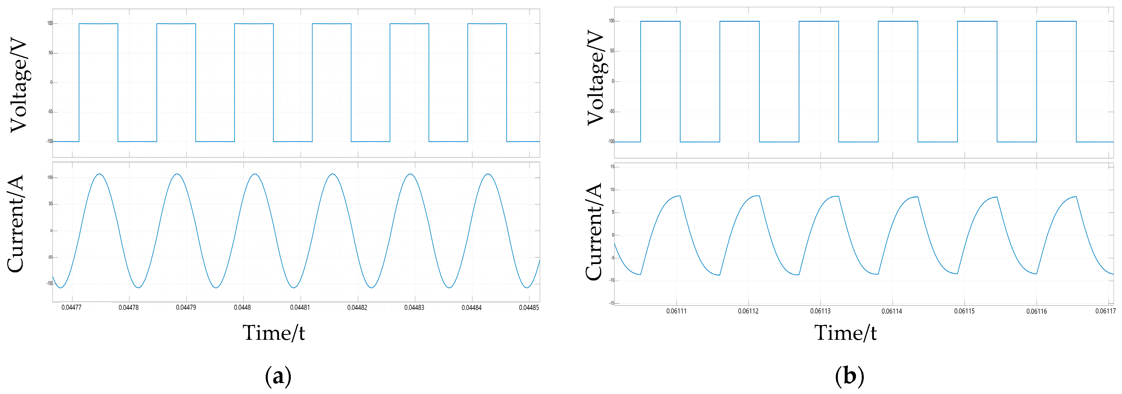
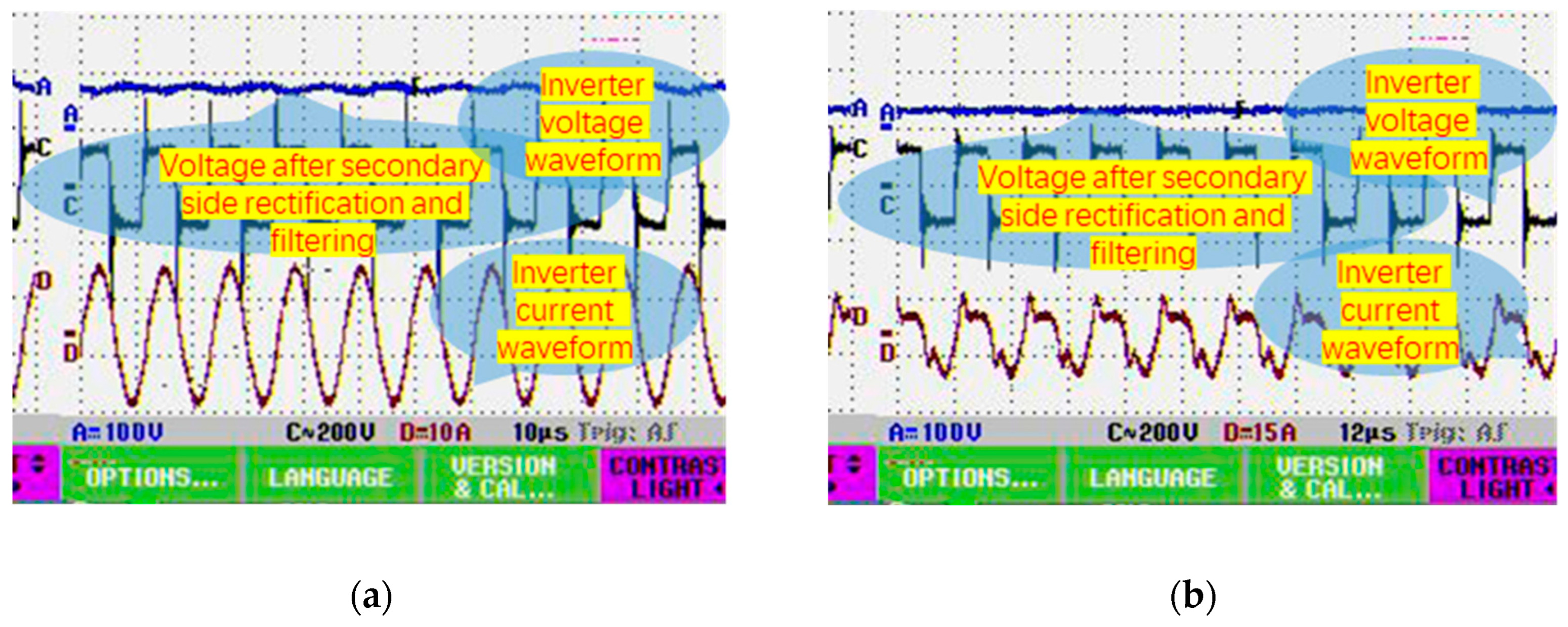
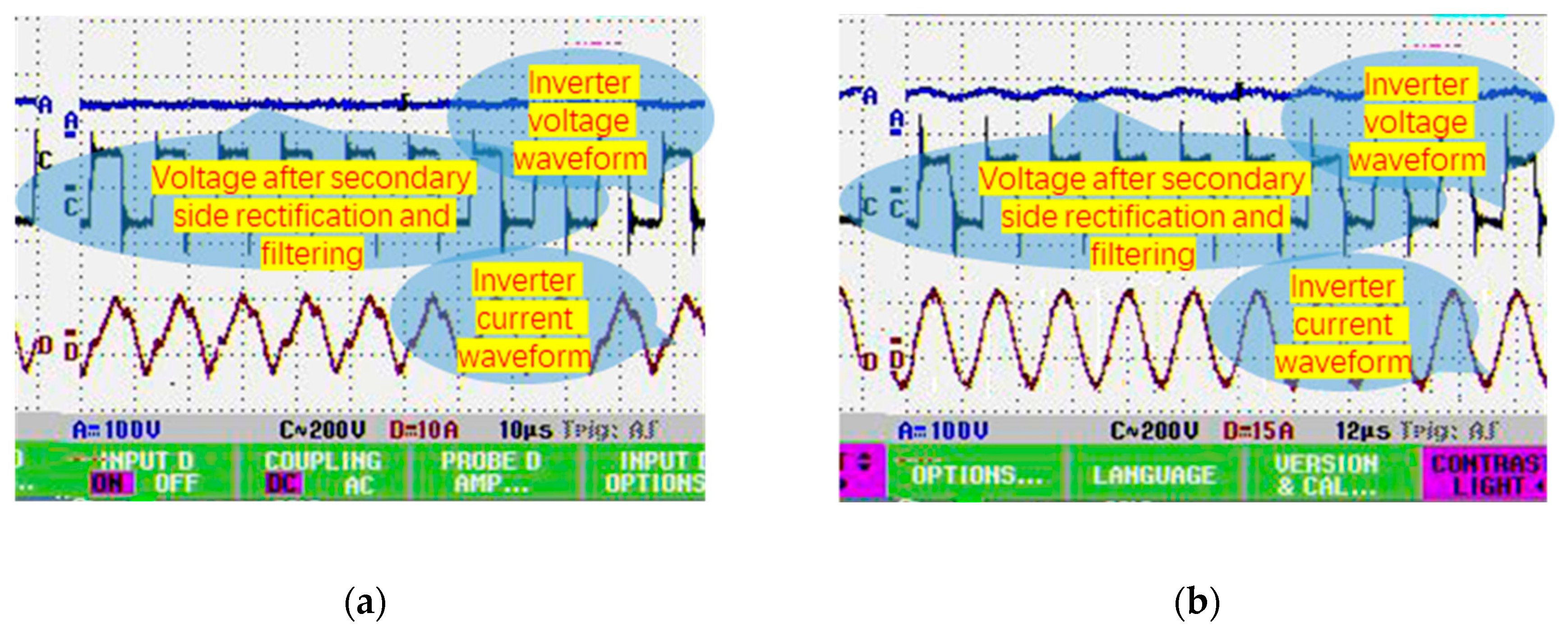
Figure 6 shows the simulation waveforms of the inverter output voltage and current when
k = 0.2.
Figure 6a shows the inverter output voltage and current waveforms at the resonant frequency of 73.5 kHz, and
Figure 6b shows the inverter output voltage and current waveforms at the resonant frequency of 90 kHz. The current waveform in
Figure 6b is non-sinusoidal, indicating that the harmonic content is high and it is easy to produce harmonic losses, especially during the device switching process, which easily leads to large switching losses. The phase difference between the inverter output voltage and current is relatively large, causing the transmission power and transmission efficiency of the system to decrease. The current waveform in
Figure 6a is a sine wave, and the current amplitude is significantly increased. The phase difference between the inverter output voltage and current is almost zero, indicating that when the resonant frequency is switched to 73.5 kHz, the output power and efficiency of the underwater wireless power transfer system are significantly improved.
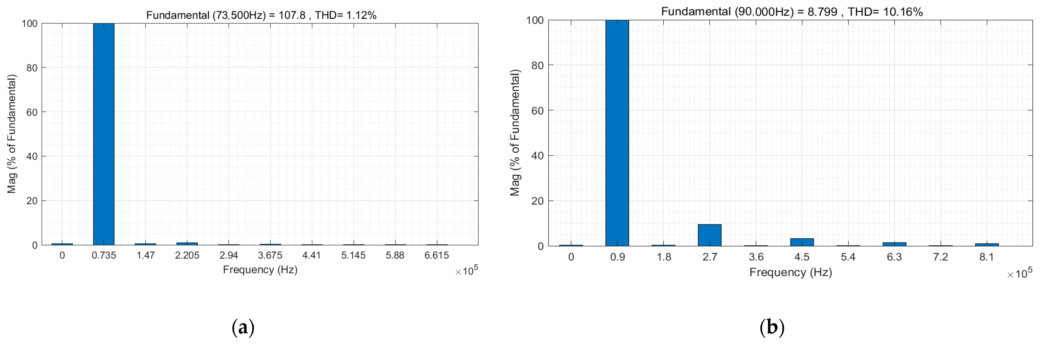
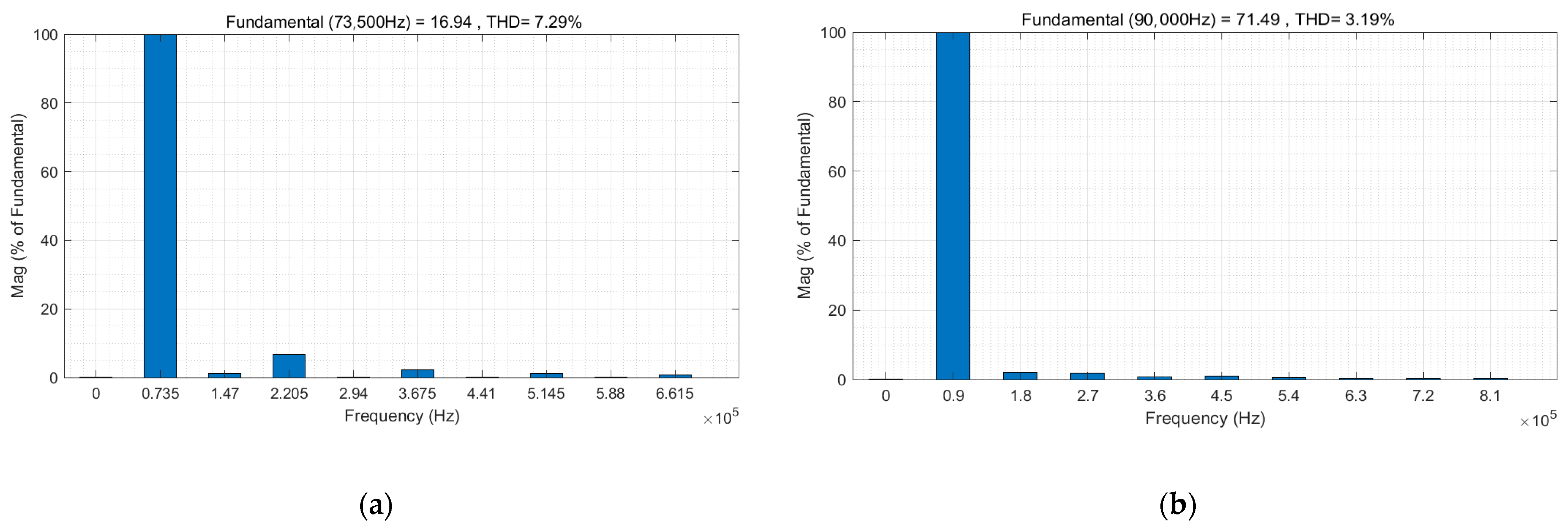
Fourier analysis was performed on the inverter current in
Figure 6a,b, and the results are shown in
Figure 7.
Figure 7b shows the current harmonic analysis at a resonant frequency of 90 kHz, where the total harmonic distortion (THD) of the current is 10.16%, and the third harmonic accounts for approximately 10% of the fundamental content while the fifth harmonic accounts for approximately 5%.
Figure 7a shows the current harmonic analysis at a resonant frequency of 73.5 kHz, where the third and fifth harmonics are significantly reduced and the THD of the current is 1.12%. The analysis indicates that if the system continues to operate at resonant frequency
ω2 when the coil is offset and the coupling coefficient decreases, the current waveform will be severely distorted, resulting in a decrease in the system quality factor. Switching the resonant frequency to
ω1 can significantly reduce the harmonic content and improve the system quality factor, thereby effectively avoiding the current waveform distortion caused by the coil offset and improving the system transmission efficiency and anti-offset capability.
If the offset between the receiving coil and the transmitting coil is small in the charging dock, a coupling coefficient
k > 0.4 will occur.
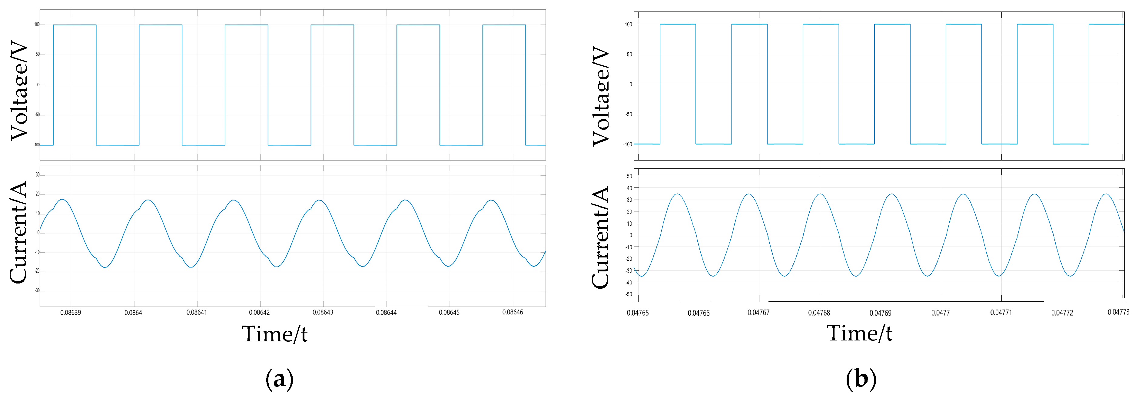
Figure 8 shows the simulation waveform of the voltage and current output of the inverter when
k = 0.6;
Figure 8a shows the output voltage and current waveform of the inverter at the resonant frequency of 73.5 kHz; and
Figure 8b shows the output voltage and current waveform of the inverter at the resonant frequency of 90 kHz. As can be seen from the figure, the system has a good transmission capacity under the resonant frequency
ω2, and the transmission capacity is significantly reduced under the resonant frequency
ω1. The inverter output voltage and current waveform phase difference are large, resulting in an excessive reactive power generation system. Fourier analysis is conducted on the current waveform in
Figure 8, and the results are shown in
Figure 9. The results show that the current harmonic content is very small under the resonant frequency
ω2, while the current harmonic content is relatively large under the resonant frequency
ω1, resulting in more harmonic loss.
The simulation results in
Figure 8 and
Figure 9 show that when the AUV is slightly offset in the charging dock, the coupling coefficient is large. Working at the resonant frequency
ω2 is more advantageous for energy transfer, with low current waveform distortion and high power and efficiency of system transmission.
The above analysis indicates that when the resonance frequency and coupling coefficient are matched, the inverter output current has a large amplitude, low distortion, and a good sine wave, and the phase difference between the output voltage and current is small, resulting in less reactive power generation and higher transmission power and efficiency. Another advantage of using a constant-voltage source output system for power transmission is that when a circuit fault occurs, the transmission power becomes zero, which can act as an automatic protection for the system.
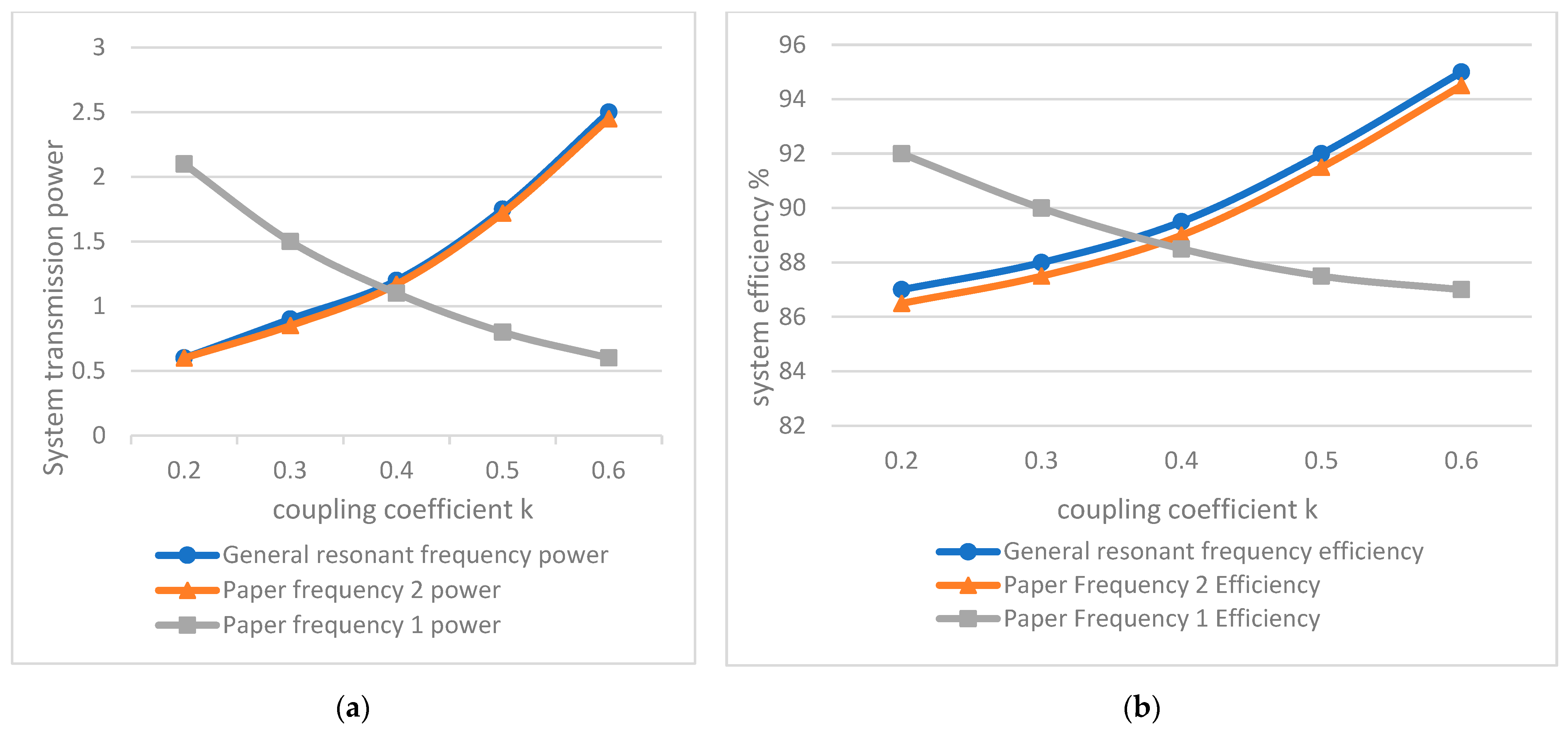
Under the identical coupling structure, the conventional double LCC resonance compensation system and the double LCC resonance compensation system with multi-resonance switching in this study are simulated and compared. The conventional double LCC resonant compensation system [
29] works at a resonant frequency of 85 kHz. In this study, the double LCC resonant compensation system with multi-resonant point switching works at
ω1 and
ω2 resonant frequencies, respectively.
Figure 10 presents the simulation comparison results of its transmission power and transmission efficiency. As depicted in
Figure 10, the transmission characteristics of the conventional double LCC resonance compensation system are similar to those at the resonant frequency
ω2 in this study. When
k > 0.4, good transmission capability is achieved; when
k < 0.4, the transmission capability turns out to be worse, whereas the coupling coefficient is low. The transmission capability of the lower system at resonance frequency
ω1 is significantly enhanced, such that the transmission power and transmission efficiency of the system can be increased through multi-resonance point switching. It can be seen from Formula (22) that the higher the coupling coefficient is, the higher the output voltage is; while Formula (23) indicates that the lower the coupling coefficient is, the higher the output voltage is; Formula (24) indicates that the higher the coupling coefficient is, the higher the system transmission power; and Formula (25) indicates that the lower the coupling coefficient is, the higher the system transmission power is, which is the same as the simulation results. It can also be seen from the figure that the coupling coefficient at the lowest power point and the efficiency point is 0.4, which is the same as the calculation result of Equation (26) and is obviously the switching point of the resonant frequency. When the coupling coefficient ranges from 0.2 to 0.6, the transmission power of the conventional double LCC compensation system declines by nearly 1.9 kW, and the transmission efficiency decreases by approximately 8% to 5.5%. Accordingly, the double LCC resonance compensation system using multi-resonance point switching is capable of significantly increasing the transmission power and transmission efficiency, while the system is endowed with higher stability and anti-offset capability.
6. Experimental Verification
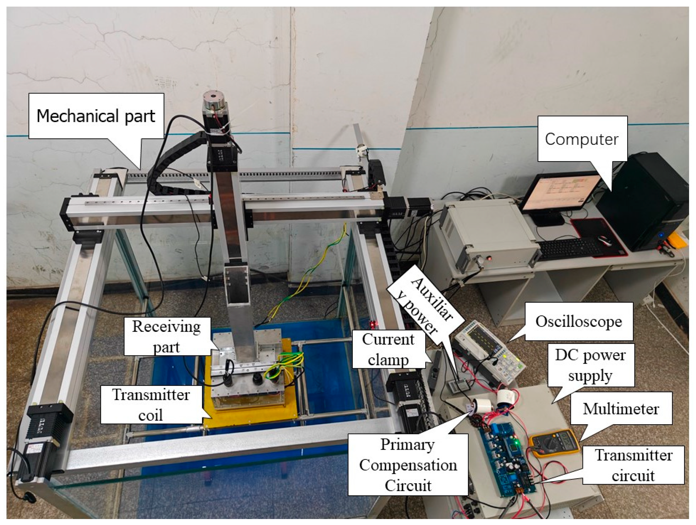
An underwater wireless power transfer system with a power of 1.3 kW is developed, and the experimental platform built is illustrated in
Figure 11. The experimental platform comprises a transmitting part, a receiving part, a compensation network, a coupling mechanism, and a mechanical part. The transmitting part can be achieved by a high-frequency inverter circuit, and the receiving part refers to a high-frequency rectifying circuit. The compensation network comprises capacitors and inductors [
30,
31,
32]. The compensation capacitors are film capacitors. Due to the advantages of high frequency characteristics, low inductance, stability, size, and integration, thin film capacitors have become the ideal choice for high frequency compensation circuits in underwater wireless charging compensation systems. The capacitors can be connected in series and parallel to achieve the capacitance required by the experiment. The compensation inductance can be determined by measurement using an LCR tester. The coupling mechanism comprises a transmitter coil and a receiver coil, both of which are wound by Litz wire. The transmitter exhibits a stacked double-coil structure, and the receiver adopts a single-layer Litz coil. The mechanical part is primarily the XYZ axis mechanical arm, with an offset adjustment accuracy of 1 mm, such that the offset test of underwater wireless power transmission can be achieved.
Table 2 lists the experimental parameters of the wireless power transfer system.
The underwater wireless charging experiment provided in this paper was carried out in a 1.2 m × 1.2 m × 1.2 m sink that was filled with water and modulated according to the concentration and characteristics of seawater. The transmitter coil was put into the water, and the receiving end was put into the water after being completely sealed. Therefore, the voltage and current can be directly observed during the charging process, and the primary-side voltage and current can be observed through the oscilloscope. The experimental test of the underwater wireless charging system is completed by moving the robot arm controlled by a computer.
During the underwater wireless power transmission offset experiment, as the coil is square-shaped, the effect of horizontal offset and vertical offset is the same. Therefore, the experiment was conducted with a horizontal offset.
Figure 12 shows the transmitter inverter output voltage, current waveform, and receiver output voltage waveform when the horizontal offset is 0 cm, where
Figure 12a is the resonant frequency of 90 kHz and
Figure 12b is the resonant frequency of 73.5 kHz. From the figure, it can be seen that when there is no offset, the sine degree of the current waveform is better at the resonant frequency of 90 kHz, and the phase difference between the inverter output voltage and current is relatively small. However, when the operating frequency is 73.5 kHz, the current waveform is distorted, the amplitude is significantly reduced, and the phase difference between the output voltage and current of the inverter increases, resulting in a significant decrease in the transmission power.
Figure 13 shows the experimental waveforms for a 20 cm lateral offset, where
Figure 13a corresponds to a resonant frequency of 90 kHz and
Figure 13b corresponds to a resonant frequency of 73.5 kHz. It can be seen from the figures that when the resonant frequency is 90 kHz, the phase difference between the output voltage and current of the inverter is large, and the current waveform has a high harmonic content and severe distortion. When the resonant frequency is 73.5 kHz, the phase difference between the output voltage and current of the inverter decreases, the distortion rate of the current waveform decreases, and the amplitude increases, resulting in an increase in the transmission power. Therefore, when the coupling coefficient decreases to a certain extent due to offset, the system has stronger power output capability at the sub-resonant frequency.
Table 3 shows the results of the underwater wireless power transfer system offset test. It can be seen from the table that as the offset increases, the transmission power and efficiency both exhibit the characteristic of first decreasing and then increasing. This is because when the offset is small, the coupling coefficient is large, and when the resonance frequency is 90 kHz, both the transmission power and efficiency are relatively large. As the offset increases, the coupling coefficient
k continuously decreases, and the system’s ability to transmit electrical energy gradually decreases. This is the same as the result obtained from the calculation of Equations (22) and (23) above. When
k =
kc, the resonance frequency switches to 73.5 kHz, and the transmission power and efficiency begin to recover. This is consistent with the results calculated by Equations (24) and (25). When the offset distance is 20 cm, the transmission efficiency can still reach 89.6%, and the electrical energy transmission capability is significantly enhanced. The experimental results are in agreement with the simulation and theoretical calculations, indicating that using multi-resonance point switching for energy transmission can make the system have strong anti-offset capability.
7. Conclusions
In this study, the underwater wireless power transfer system with double LCC resonance compensation is taken as the research object. Based on the mutual inductance coupling model, the mathematical model of the double LCC compensation network is derived, and the power transmission characteristics of multiple resonance points are analyzed. As revealed by the comparative analysis of the output power, transmission efficiency, and current harmonics at the two resonance points of the system, the system has a stronger power output capability at the sub-resonance point when the offset causes the coupling coefficient to drop to a certain extent. Multiple resonance points and power transmission characteristics are matched through the frequency relationship, appropriate resonance frequencies are selected based on different coupling coefficients, and the mutual switching method of multiple resonance points is adopted, such that the transmission power and transmission efficiency of the system can be effectively improved. In the simulation analysis, when the coupling coefficient is high, the resonant frequency reaches 90 kHz for power transmission. When the coupling coefficient is 0.6 under the rated load, the system output current waveform distortion rate is 3.19%, and the power transmission efficiency reaches 93%. When the coupling coefficient is low, the resonance frequency is used. The frequency is 73.5 kHz for power transmission. When the coupling coefficient is 0.2 under the rated load, the current waveform distortion rate is 1.12%, and the power transmission efficiency is 90%. Notably, the double LCC resonance compensation system with multi-resonance point switching is capable of reducing current harmonics and increasing transmission efficiency. In experimental research, when no offset exists between the coil at the receiving end and the coil at the transmitting end, the transmission power and transmission efficiency of the system reach their maximum at the resonant frequency of 90 kHz. It is reduced by the rise in volume. When the coil offset exceeds 10 cm, the transmission power and transmission efficiency of the system increase significantly with the rise of the offset after the resonant frequency is switched to 73.5 kHz. As revealed by the result of the simulation and experiments, the double LCC compensation network is capable of achieving the output characteristics of constant-voltage/constant-current of the wireless power transfer system. Furthermore, the system is characterized by strong transmission capability and anti-offset capability.
Further research will focus on designing the switching process of frequency points, developing a suitable switching mode, and achieving constant-current and constant-voltage output of the system under the premise that ensuring the overall stability of the system is the next key issue to be solved. At present, there are two modes of frequency switching available: one is frequency switching through the form of jump change, and the other is frequency switching through the form of linear change. Therefore, the future direction of this study will be to compare the advantages and disadvantages of the two switching modes and choose the optimal switching mode for the system.


