1. Introduction
Nowadays, many industrial applications that involve the handling or processing of physical, chemical, or biological substances rely heavily on high-precision measurement instrumentation. One of the most commonly used systems for this purpose is the QCM (quartz crystal microbalance), which detects the resonance and frequency shifts of quartz crystal resonator (QCR) sensors. In this context, QCM sensors are widely used in different application domains. QCM sensors find wide application in various domains due to their high sensitivity and real-time capability of measuring minute mass changes (typically in the order of a few ng/cm
2) within a broad dynamic range (100 μg/cm
2). This makes them particularly attractive for applications such as bio-sensors, analysis of biomolecular interactions, and studying cell–substrate interactions [
1]. Usually, to perform high-precision measurements, accurate frequency (/time) measurement techniques are employed using electronic resonators based on circuits containing capacitors, resistors, and/or inductors [
1]. These circuits generate alternating current by periodically fluctuating between two voltage levels. Oscillators working with optimal stability rely on vibrating quartz crystals, which exhibit a stable frequency when a direct current is applied. Similarly, a piezoelectric oscillator circuit uses a piezoelectric crystal in combination with electronic passive components to generate a stable frequency depending on crystal properties and environmental conditions [
2]. Factors such as temperature, pressure, acceleration, radiation, electric fields, and electromagnetic fields can introduce variations in the nominal generated frequency oscillation. As a result, sensors based on piezoelectric oscillators offer accurate measurement of these physical variables [
3]. Therefore, piezoelectricity based on the quartz crystal microbalance is one of the most popular mass sensing techniques in industrial applications, including gas and liquid sensors [
2,
3,
4] and electronic tongues [
5]. These applications include molecular recognition [
6,
7,
8] and food quality control [
4,
9,
10,
11]. QCM is a low-cost and highly sensitive mass measurement technique that was discovered in 1959 by Sauerbrey [
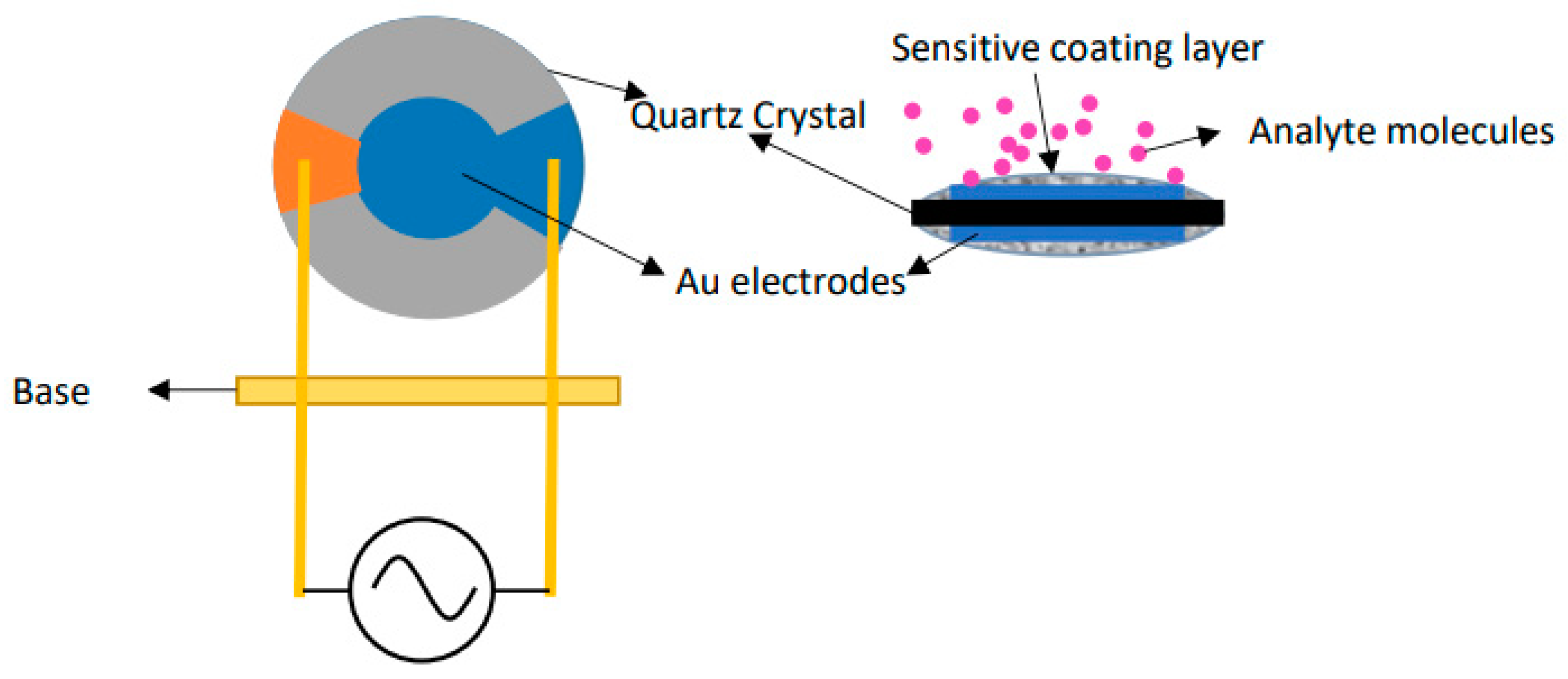
12]. Sauerbrey established a relationship between the mass on the surface of the crystal and its resonance frequency. More precisely, as depicted in
Figure 1, the addition of mass distributed over the quartz crystal surface alters the nominal oscillation frequency. This frequency variation can be described by the following Sauerbrey Equation (1):
Here, represents the normalized frequency change (Hz) as a function of the mass change (gram), is the resonant frequency (Hz), is the piezoelectrically active crystal area (area between electrodes, ), is the density of quartz (2.648 g/), and is the shear modulus of quartz for AT-cut crystal (2.947 × g··).
Therefore, the resonance and subsequent frequency shift of the quartz crystal resonator is detected by a QCM measurement system. A QCM crystal consists of a thin quartz crystal with metallic electrodes of a certain thickness on both sides. This pellet is produced with different thicknesses, resulting in different frequencies. Gold is often used for the electrodes due to its resistance to corrosive environments [
14]. There are three main electronic techniques used for frequency shift measurements: impedance measurement, quartz crystal microbalance with dissipation (QCM-D), and oscillator-based measurements [
15]. Among these techniques, impedance measurement provides the most precise results for resonance frequency analysis [
16]. It involves applying a sweeping frequency signal to a quartz crystal resonator and collecting impedance spectrum (or admittance) data to determine the resonant frequency and dissipation outputs. QCM-D is a type of quartz crystal microbalance based on the ring-down technique. It is often used to determine film thickness in a liquid environment, such as the thickness of an adsorbed protein layer. It can be used to study other properties of the sample, such as its softness. The QCM-D technique allows measurement of several times per second in a vacuum, gaseous, or liquid environment [
17]. Additionally, it is possible to switch between fundamental frequency and overtones [
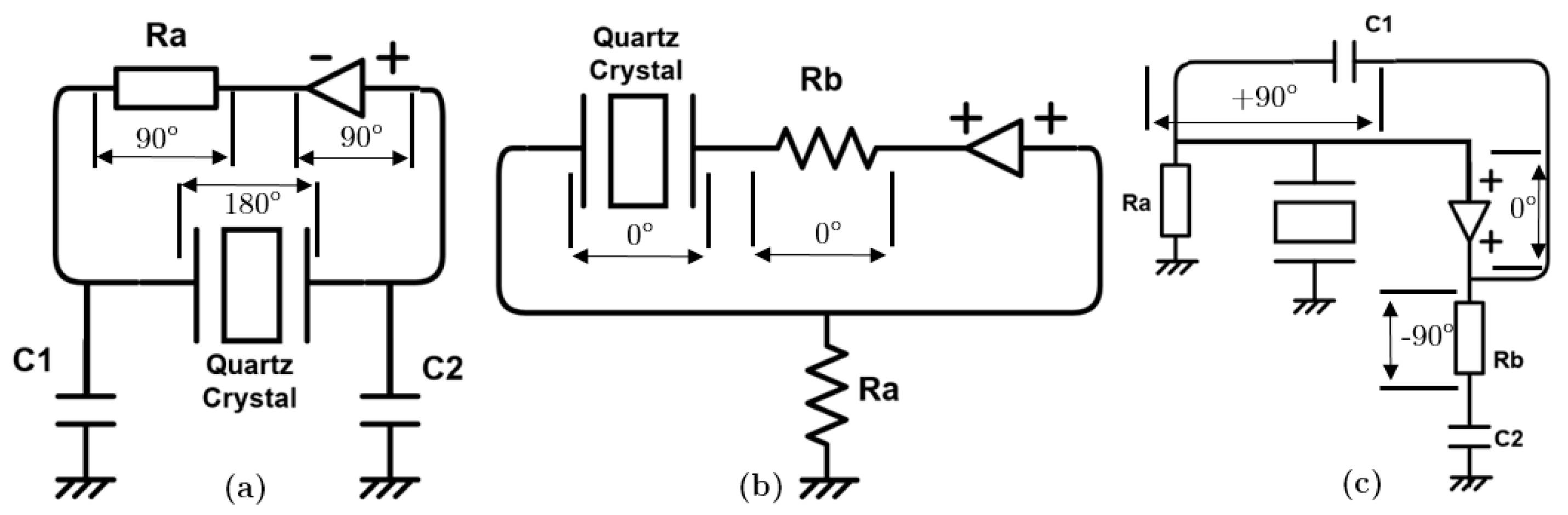
18]. Although QCM-D and impedance measurement systems are efficient and commercially available, they are often expensive and cumbersome. They are not adequate for on-site use. The principles of oscillator-based measurement, distinguishing inverting and non-inverting amplifier oscillators, are illustrated in
Figure 2. On the one hand, the inverting amplifier, known as a Pierce oscillator (shown in
Figure 2a), adds a 180° phase shift which is compensated by the feedback network (based on
,
,
passive components and the quartz crystal) to meet the phase requirement in the Barkhausen criterion. On the other hand, the non-inverting amplifier (shown in
Figure 2b) acts on the sensor as a series resonator satisfying the phase condition at the series resonance frequency by only using resistor components (
,
).
Figure 2c illustrates another non-inverting amplifier known as a Colpitts oscillator, where the sensor functions as a high-quality inductor through its connection in parallel with
,
passive elements.
The QCM is widely used due to its extreme sensitivity to the characteristics of the materials it comes into contact with, leading to shifts in its resonant frequency. However, the effectiveness of the QCM is constrained by the noise specifications of the crystal oscillator and the resolution of the frequency counter employed to measure frequency variations. Usually, the standard QCM System is a stand-alone instrument with the built-in quartz crystal oscillator electronics, frequency counter, and CPU/microcontroller ensuring the measurement, the monitoring, and the display (on a front panel) of the shifts in resonance frequency, which is dependent on the material with which the QCM is in contact. Consequently, an input stimulus induces a frequency shift in the sensor. Therefore, precise quantification of changes in the input stimulus is achievable, provided an appropriate frequency counter/meter is utilized. Unfortunately, it is well known in the field of time–frequency metrology that attaining higher measurement accuracy necessitates longer measurement times. To mitigate this, QCM systems incorporate a phase-locked loop (PLL) electronic circuit, which reduces the measurement time [
20]. Nevertheless, such systems are neither cost-effective nor suitable for developing a multi-channel QCM system. Each QCM would require a quartz crystal resonator oscillator, a PLL, a low-pass filter, and an amplifier circuit.
Static random-access-memory-based field programmable gate array (SRAM-Based FPGA) technology provides a parallel computation capability which offers performance improvements while ensuring flexibility compared with traditional CPU processing architectures. Moreover, FPGAs provide Input/Output Blocks (IOBs) which can be used to implement additional logic with CLBs to improve design performance by increasing available logic and routing resources. Previous works show interest in using FPGA for the integration of a frequency measurement technique providing a trade-off between performance and accurate measurement [
21]. Similarly, several works have explored the utilization of FPGAs in QCM systems for conventional counter-based frequency measurement, with or without compensation circuits [
22,
23]. For example, a low-cost prototype of a multi-channel quartz crystal microbalance data acquisition system for QCM sensor investigation was developed in 2018 [
10]. It uses a totally external oscillator to keep the oscillation down. The 16-bit time counters of the PIC16F allow frequency measurement to be performed by QCM sensors with a sensitivity of 1 Hz. However, all of these prior works required additional external chips to realize the QCM oscillators and generate the reference signal based on a subdivision of a highly accurate local clock oscillator.
This paper presents a proposal to implement a commonly used Pierce-gate crystal oscillator based on a quartz crystal using configured Input/Output Blocks (IOBs) within an FPGA. By incorporating digital inverters and a feedback resistor, the inner digital CMOS inverter can be linearized, effectively transforming the logic inverter gate into an analog amplifier. This approach allows for the utilization of low-cost external passive components (such as C1 and C2 reactance and Rs) that satisfy the Barkhausen criteria.
Input/Output Blocks connect internal FPGA architecture to the external design via interfacing pins, eliminating the need for external chip oscillators, such as resonators, PLLs, amplifier circuits, or filters. Moreover, the FPGA’s logic elements, which serve as the fundamental building blocks, can be programmed to carry out different functions as required by the design, enabling the implementation of accurate frequency measurement using the GPS as a reference signal. The main novelty of the proposed FPGA-based system lies on the use of internal IOBs and its ability to perform a multi-QCM measurement system composed of several oscillators, each equipped with a QCM. Within this system, Pierce oscillators utilize on-chip inverting amplifiers within the IOBs of the FPGA, striking a balance between achieving accurate frequency measurements (which can be enhanced through fine measurements based on a ring oscillator or time-to-digital approach) while minimizing the use of logic resources within the FPGA and external components. Therefore, the frequency measurement is accomplished through the implementation of a 32-bit reconfigurable reciprocal frequency meter architecture, which relies on the GPS reference signal and the measurements taken when it is connected to different QCMs.
The remaining sections of the paper are structured as follows.
Section 2 outlines the proposed system, which integrates parallel quartz crystal oscillators using only IOBs connected to multiple QCMs simultaneously. This section describes the reciprocal counter implemented in FPGA (with the potential for enhanced accuracy through the implementation of a time-to-digital converter (TDC) in the FPGA).
Section 3 investigates the resonant conditions for various QCMs, providing details on the experimental setup, measurement results, and subsequent discussion of the findings. Finally,
Section 4 presents the conclusion of the study along with directions for future work.
2. Frequency Measurement Electronic System
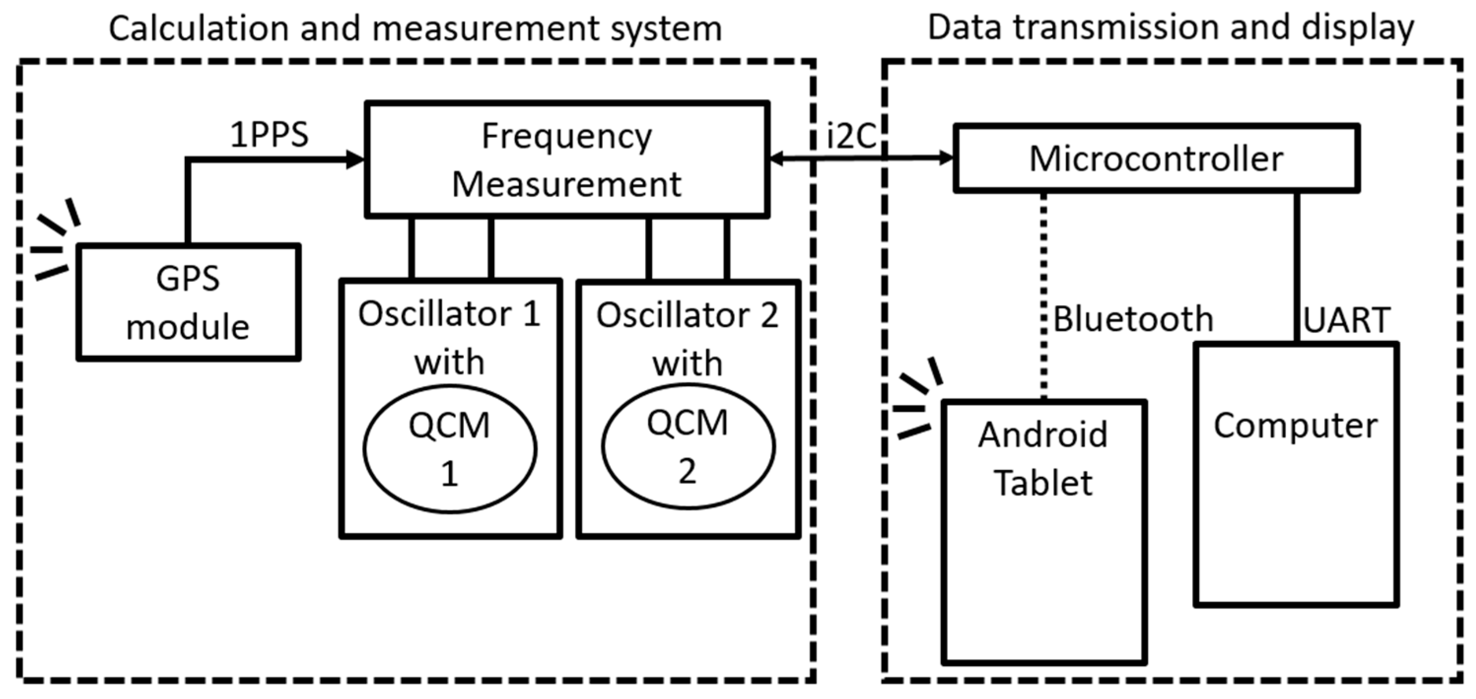
Figure 3 illustrates the overall electronic measurement system of the proposed multi-channel QCM data acquisition system, which incorporates two QCM resonators. The embedded frequency measurement system comprises both hardware and software components.
The embedded hardware employed in this study utilizes an accurate FPGA-based frequency measurement system implemented on the Xilinx Virtex 6 FPGA ML605 stand-alone platform [
24]. The software part, executed on a microcontroller, is responsible for collecting frequency data and transmitting this to a display. This proposed electronic communication system incorporates an embedded processor that utilizes Bluetooth communication with a custom-developed Android application. This application receives and stores data from the frequency measurement hardware system in the form of a spreadsheet. This electronic system ensures the transmission of data acquired from the sigma-delta converter through the utilization of the I2c protocol. More precisely, serial data (SDA) and clock (SCL) signals are used to perform the I2c protocol ensuring data transmissions. One on-board microcontroller on the red PIC32MX470 development board manages the communication with the FPGA via the I2c protocol. The timer configuration is used to set the measuring rate. The UART link is used to send the results from the microcontroller to the computer in order to fill in a spreadsheet. The timer defines the delay between each acquisition request for digital frequency values. The Android application manages the reception of measured values via the Bluetooth protocol and displays in one tablet device. In summary, the microcontroller is responsible for managing frequency measurements, which are conducted by the FPGA directly connected to multiple QCM measurement channels.
A multi-channel reciprocal counter is implemented within the FPGA Virtex-6, utilizing a 200 MHz local clock reference signal. The timegate (measurement time) for counting rising edges of the reference signal is set to one second, corresponding to a 1PPS GPS signal received with a jitter of approximately 20 ns from the MediaTek GPS Chipset MT3339 of the Adafruit GPS module [
25]. This received GPS reference signal provides an efficient, stable, and cost-effective solution for generating an accurate timegate reference signal, enabling high-frequency resolution in frequency measurements.
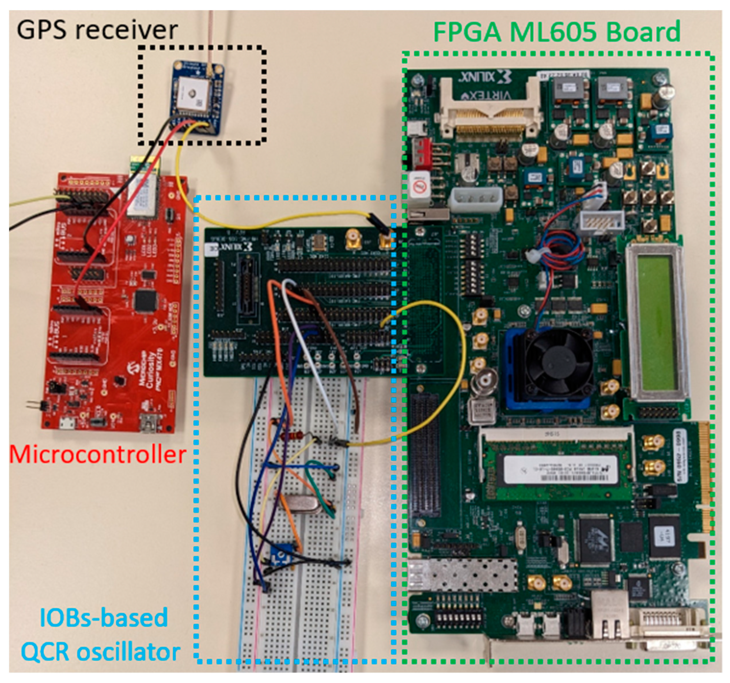
Figure 4 showcases a photo of the proposed embedded hardware system for QCR oscillator multi-channel frequency measurements.
2.1. Frequency Measurement System
Usually, low-cost FPGA-based frequency measurement relies on a frequency counter that incorporates timers and logical counters. The basic digital measurement of frequency involves counting the number of rising edges of the input signal during a predetermined time interval, utilizing a stable clock reference signal. The resonance frequency can then be obtained using Equation (2), where
f represents the measured resonance frequency,
N denotes the measured number of input pulses, and
t indicates the measurement time.
Depending on the frequency of the clock reference signal, the accuracy of the measurement improves as the duration of the measurement time increases. If we use a basic frequency counter (according to Equation (2)) with a measurement window of one second, we will reach a maximum accuracy of ±1 Hz. However, for QCM applications that require higher frequency resolution and/or shorter measurement time, modern frequency counters employ the reciprocal counting method [
26]. Unlike previous approaches that solely rely on a high-frequency reference signal, the proposed reciprocal counter utilizes two signal references: a high-frequency clock signal for frequency calculation and the received GPS signal for period measurement. This approach offers an alternative solution for achieving more accurate measurements without the need for subdivision of the high clock reference signal.
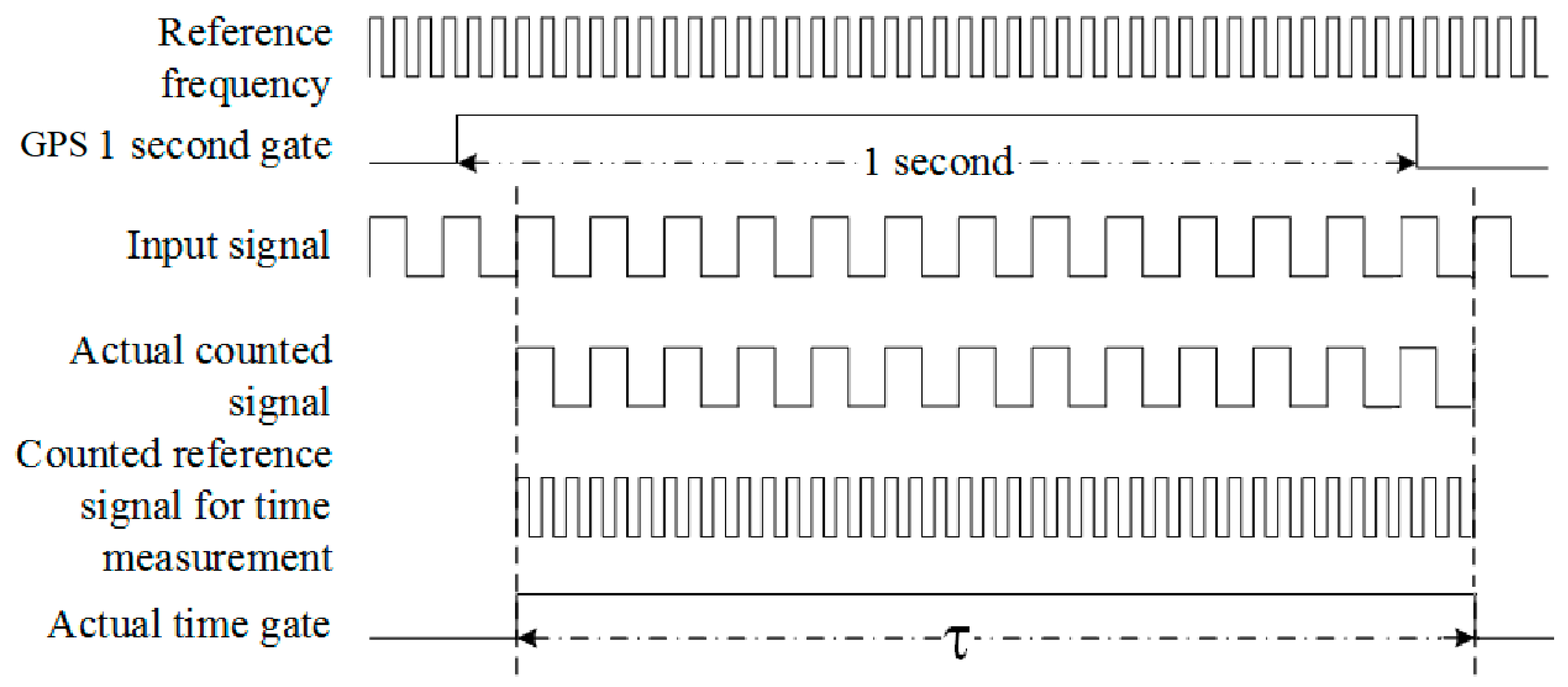
Figure 5 illustrates the reciprocal counting method using the GPS Signal.
For a duration of one second, each clock edge of the input signal is counted N times. Simultaneously, a reference signal is also counted for the exact same duration. This duration, referred to as τ, represents the time delay between the first rising edge of the input signal following the rising edge of the one-second period signal, and the first rising edge of the input signal following the falling edge of the 1 Hz signal. The main advantage of this method is its resolution, which remains unaffected by the input frequency and can be enhanced through the utilization of low-cost FPGA-based digital counting techniques (DCTs) for time stamping the start and stop edges of the input signal. Moreover, the error remains constant across the entire range of input signal frequencies and can be reduced as the reference clock frequency increases or as the gate time extends.
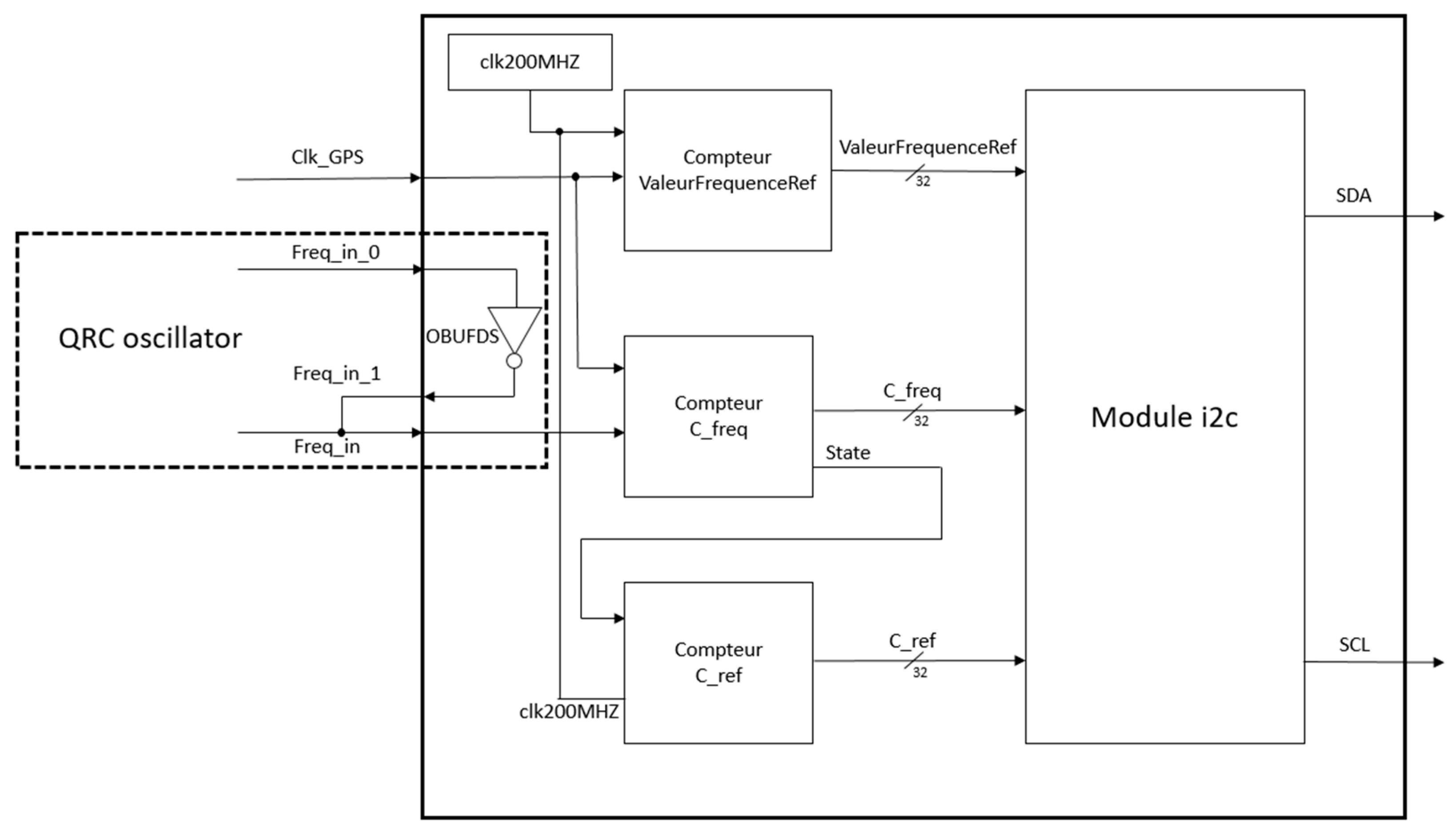
Figure 6 illustrates the internal architecture of the FPGA reciprocal counter designed for measuring the frequency of a single QCR oscillator. This design incorporates three digital counters, each 32 bits in size, responsible for counting the various edge events of the input oscillation signal. These counters enable the calculation of the frequency value or frequency shifts resulting from the input QCM stimulations connected to the FPGA’s IOBs. The first counter, denoted ValeurFrequenceRef, provides the count result of the high frequency reference delineated by the input GPS signal. This measurement provides a real-time accurate measurement of the reference frequency. The second counter, referred to as C_Freq, counts the number of rising edges of the signal to be measured (the output oscillation signal for one Pierce QCM oscillator) within the time period τ. Finally, the last counter performs the task of counting the number of rising edges of the reference signal during the designated period τ in order to obtain the frequency measurement of the input signal by considering Equation (2).
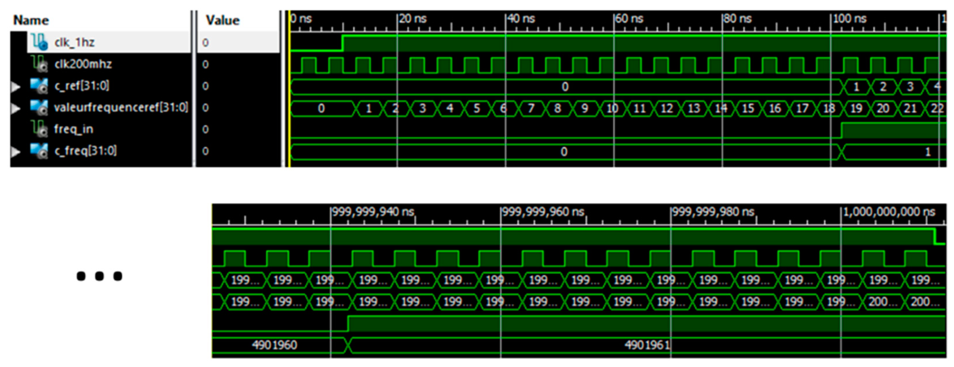
Behavioral simulations and timing were conducted to evaluate the accuracy of the proposed test using the Xilinx Virtex-6 ML 605 platform. These simulations demonstrated the highly accurate frequency measurement of the oscillating QCM signal obtained from an on-chip FPGA IOB logic inverter. The simulation results of the proposed architecture, which utilizes the GPS-based reciprocal counting method, are presented in
Figure 7. These results were obtained through the utilization of VHDL description and the Xilinx FPGA ISE Environment design tool.
The design of the proposed reconfigurable frequency meter incorporates the GPS and oscillating QCM signals as inputs (represented by clk_1 hz and freq_in signals in
Figure 7). The behavioral simulation results demonstrate the functionality and the accurate values obtained by three counters (C_Ref, ValeurFrequenceRef, C_Freq) in accurately measuring the frequency of the freq_in signal. These measurements take advantage of the precision of the GPS sensor (clk_1 hz signal) and a local clock frequency of 200 MHz (clk200mhz signal). The accurate frequency calculation is performed according to Equation (3), as depicted in
Figure 5.
2.2. Oscillator Realization
The resonance time of QCM crystals exhibits a low oscillation amplitude, typically measured in millivolts. Therefore, sensors are connected directly to the oscillator circuit to preserve the signal level and shape. However, the crystal signal can suffer from attenuation and interference as it traverses various contact points such as the crystal holder and connectors before reaching the circuit. To address this issue, great care has been taken in selecting the connecting components, and proactive measures have been employed to position the oscillator components away from strong magnetic fields and power connections.
As mentioned, the on-chip IOB inverters of the FPGA are configured as OBUFDS elements [
27] to directly facilitate the implementation of Pierce QCR oscillators. This novel approach, not previously proposed in the existing literature on multi-channel QCM measurement systems, enables the realization of low-cost QCR oscillators.
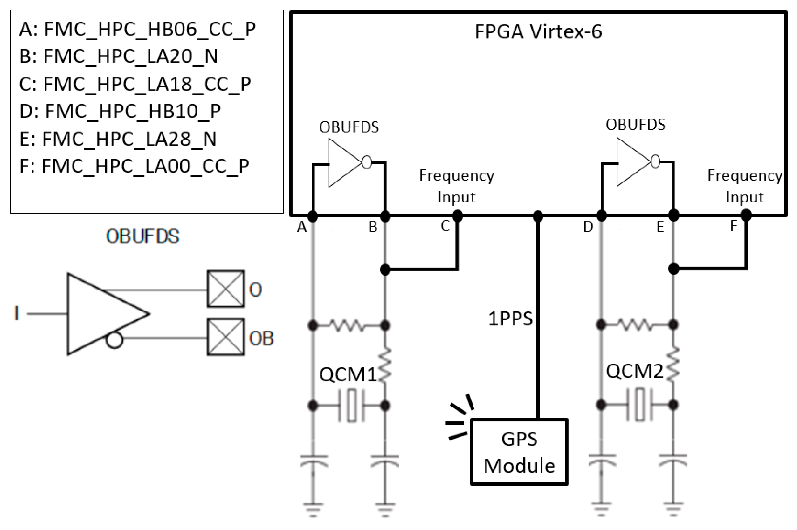
Figure 8 describes the proposed IOBs’ configuration and connection to create multi-channel QCR oscillators. Pierce oscillators are implemented with QCM connected to the FPGA realizing the inverting gate for the oscillator circuits responsible for generating the frequency oscillation signals to be measured. For this purpose, some input pins of the FPGA are connected to QCR by using the connection pins of the FMC XM105 expansion card (see
Figure 4). For the input frequency signal to be measured (i.e., the oscillator output signal), “Clock Capable” pins ending in “_CC_” are used. For the OB output signal of the OBUFDS component, pins ending in “_N” must be used, and for the O output signal of the OBUFDS component, pins ending in “_P” should be used. In order to ensure adjacent output ports, the positive and negative outputs are positioned on the same IOB side.
3. Implementation and Experimental Results
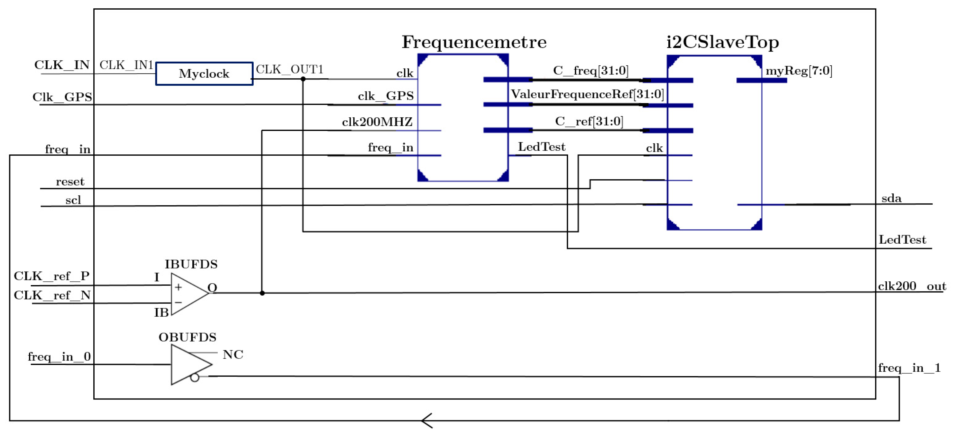
The proposed reconfigurable standalone measurement platform with communication capabilities combines both software resources, which bring the necessary versatility, and the logic hardware resources in which the accurate frequency measurement unit is implemented. To implement and test with multiple QCM sensors, the proposed design based on the Xilinx XC-6 ML 605 technology is integrated as a new core with specific components as described by the corresponding block diagram shown in
Figure 9. The proposed block design includes the following four main modules:
- -
The Frequencemetre module, which corresponds to the proposed reciprocal counter and delivers a 32-bit sequence of three counter values representing the digital frequency measurement, as determined by Equation (3).
- -
The I2c_Slave_top module, which represents a hierarchical communication using the I2c protocol that is connected to and exchanges data with the microcontroller for the purpose of frequency measurement display. This module receives the counter values from the Frequencemetre module and transmits them via the I2c communication link to the microcontroller (PIC32MX) for further processing and display of the corresponding normalized frequency change (in Hz) based on the QCM microbalance oscillation.
- -
The OBUFDS block, which is the inner logic oscillator circuit that provides the oscillating QCM signal while reducing the need for extra external logic circuits to function as an inverting amplifier oscillator.
As shown in
Figure 9, the configured IOBs function as external oscillators ensuring multi-channel measurement as illustrated in
Figure 8. For this purpose, two IOBs are necessary to achieve a single-channel QCM oscillator. More precisely, one IOB (OBUFDS block) is configured as one logic inverter, which is combined with the external passive elements (C1 and R1 as described in
Figure 2) to create an on-chip piezoelectric QCM oscillator within the FPGA. The second IOB is configured as a single-input buffer (IBUFDS-configured IOB), serving as an intermediary element that ensures the signal source remains unaffected by the load attributes while delivering a voltage and current similar to what it receives at its input.
The proposed accurate multi-channel frequency measurement is described by using hardware description language (VHDL), and the final binary configuration file is implemented on Xilinx Virtex 6 XC6VLX240T-1FFG1156 FPGA.
Table 1 provides a breakdown of the required logic synthesis resources for the system, which include two QCR oscillators connected to the FPGA. The resource utilization is as follows: 733 Slice registers, no DSP multipliers, and no block RAM. This results in a low-cost logic consumption, with 188 slices, 733 flip-flops, and 13 IOBs, all operating at a maximum frequency of 324 MHz. The architecture exhibits a dynamic power of 0.120 W, with a total supply power of approximately 3.618 W. Compared with a similar previous work [
28], the proposed system for multi-channel measurement eliminates the need for Block RAM or specific digital clock managers (DCMs) associated with multiple GCLKs used as delay-locked loop (DLL) for accurate measurement [
28]. Moreover, due to the Xilinx FPGA technology, the proposed system consumes over five times less dynamic power than other DCM- or DLL-based systems which require a minimal dynamic power of 727 mW and 662 mW, respectively, with a 100 MHz clocking frequency [
29].
To validate the system’s performance, a test platform consisting of multiple QCM sensors in a homogeneous liquid (distilled water) was utilized.
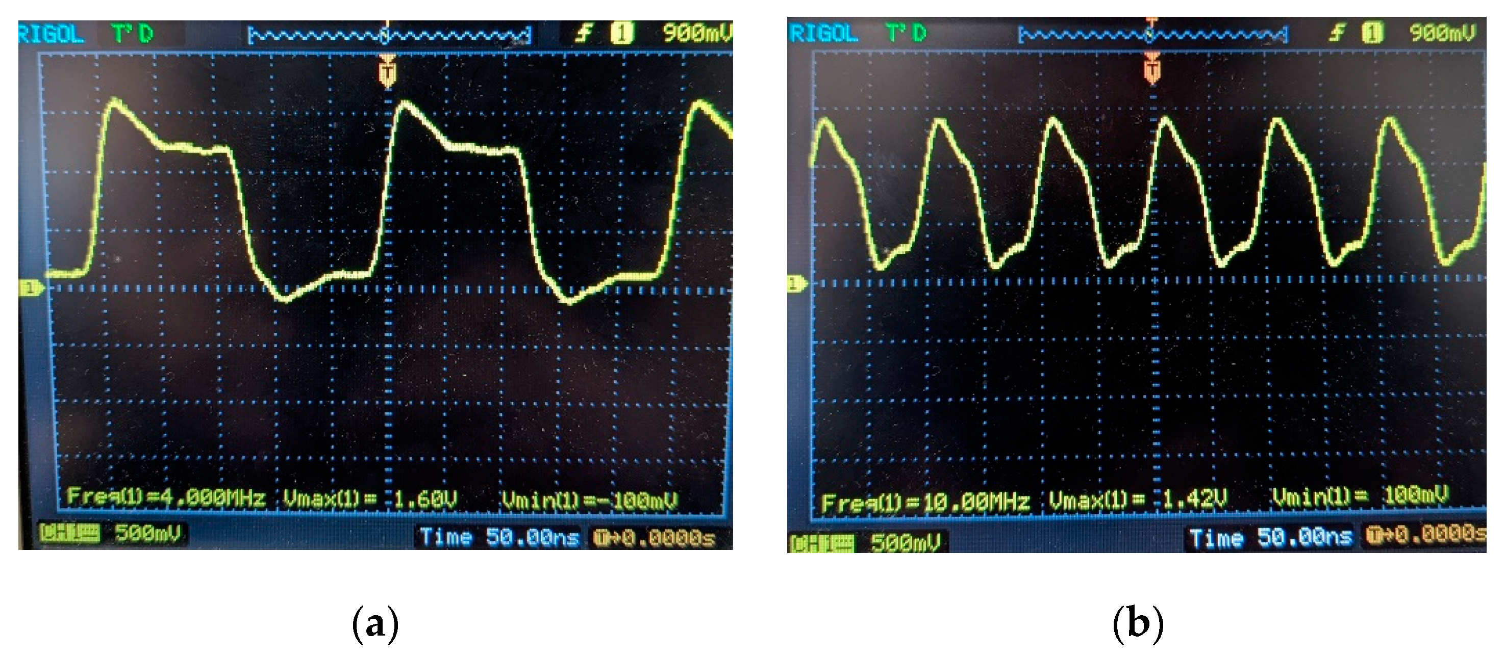
Figure 10 displays the measurement obtained by the proposed multi-channel QCM from output signals of 4 MHz and 10 MHz QCR oscillators. These signals were obtained using OBUFDS differential inverters to perform 4 MHz and 10 MHz on-chip FPGA Pierce oscillator using only external passive components (see
Figure 4). We observed that the IOBs of the FPGA ensure the oscillation of several quartz crystals without the need for additional external logic circuits, as commonly utilized in previous QCM measurement systems. Therefore, the proposed integrated QCRs maintain the oscillation of the signals; these are directly measurable by the Frequencemetre module within the FPGA. These tests validate the functionality of the FPGA-based multi-channel QCM measurement system, which operates effectively without external QCRs and provides accurate real-time frequency measurements.
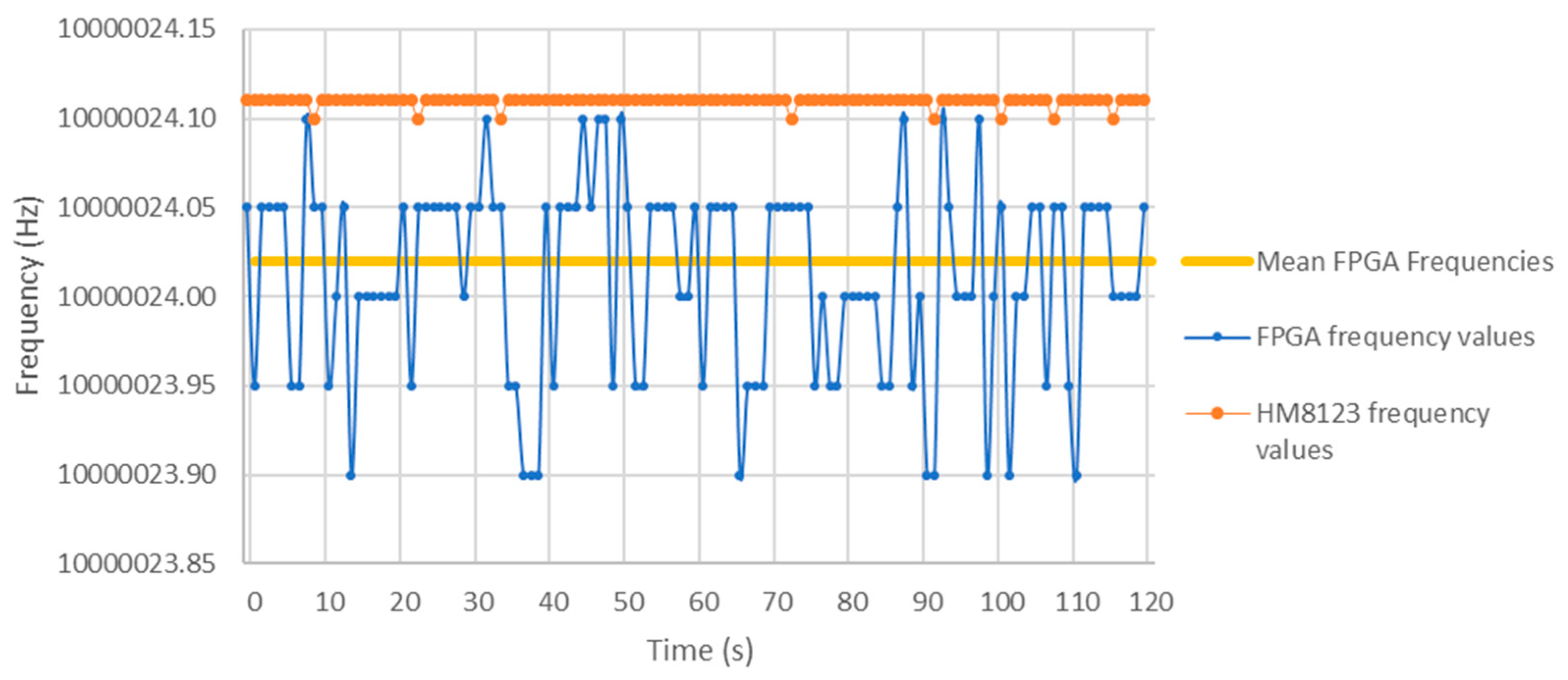
In order to assess the accuracy of the proposed FPGA-based frequency meter design, we conducted a series of comparative measurements. We used an input signal from a 10 MHz MicroCrystal OCXO oscillator, reference “OCXOV-AV5-10.000”, which provided a frequency stability of ±0.2 ppm. This reference signal is measured both by a frequency meter (Rohde and Schwarz Hameg HM8123 (OCXO Version)) and the proposed FPGA Virtex-6 frequency measurement system. The HM 8123 counter frequency measurement error is
. It represents the frequency instability of the counter, in the temperature range of 0–50 °C. A 120-second series of measurements can be seen in
Figure 11. On all the measurements taken, it can be seen that the difference (Δf) between the mean value of measured frequencies by the HM8123 m and the mean values measured by the frequency meter implemented in the FPGA is less than 0.1 Hz. In
Figure 11, Δf is approximately 0.09 Hz. We can therefore consider that under normal operating conditions, the accuracy of our system is better than 0.1 Hz.


