Article

A Patch Antenna with Enhanced Gain and Bandwidth for Sub-6 GHz and Sub-7 GHz 5G Wireless Applications

by
Shehab Khan Noor
1,
Muzammil Jusoh
1,*,
Thennarasan Sabapathy
1,
Ali Hanafiah Rambe
2,
Hamsakutty Vettikalladi
3,
Ali M. Albishi
3 and
Mohamed Himdi
4
1
Advanced Communication Engineering (ACE), Centre of Excellence, Faculty of Electronic Engineering Technology, Universiti Malaysia Perlis, Kangar 01000, Malaysia
2
Department of Electrical Engineering, Universitas Sumatera Utara, Medan 20155, Indonesia
3
Electrical Engineering Department, College of Engineering, King Saud University, Riyadh 11421, Saudi Arabia
4
Institute of Electronic Technologies Research (IETR), University of Renne, 35042 Renne, France
*
Author to whom correspondence should be addressed.
Electronics 2023, 12(12), 2555; https://doi.org/10.3390/electronics12122555
Submission received: 8 May 2023 / Revised: 2 June 2023 / Accepted: 4 June 2023 / Published: 6 June 2023
(This article belongs to the Topic Antennas)

Abstract

:
This paper presents a novel microstrip patch antenna design using slots and parasitic strips to operate at the n77 (3.3–4.2 GHz)/n78 (3.3–3.8 GHz) band of sub-6 GHz and n96 (5.9–7.1 GHz) band of sub-7 GHz under 5G New Radio. The proposed antenna is simulated and fabricated using an FR-4 substrate with a relative permittivity of 4.3 and copper of 0.035 mm thickness for the ground and radiating planes. A conventional patch antenna with a slot is also designed and fabricated for comparison. A comprehensive analysis of both designs is carried out to prove the superiority of the proposed antenna over conventional dual-band patch antennas. The proposed antenna achieves a wider bandwidth of 160 MHz at 3.45 GHz and 220 MHz at 5.9 GHz, with gains of 3.83 dBi and 0.576 dBi, respectively, compared to the conventional patch antenna with gains of 2.83 dBi and 0.1 dBi at the two frequencies. Parametric studies are conducted to investigate the effect of the parasitic strip’s width and length on antenna performance. The results of this study have significant implications for the deployment of high-gain compact patch antennas for sub-6 GHz and sub-7 GHz 5G wireless communications and demonstrate the potential of the proposed design to enhance performance and efficiency in these frequency bands.

1. Introduction

5G mobile communication systems have significantly improved over the last few decades and are in high demand due to their significant advantages, including low latency, high data rate, and high data capacity [1]. The usage of high data rates, wide bandwidth, and stable gain, which are already in use in many regions, will be greatly impacted by 5G. The 5G New Radio includes frequency bands such as n77 (3.3 GHz–4.2 GHz), n78 (3.3 GHz–3.8 GHz), and n79 (4.4 GHz–5.0 GHz) for sub-6 GHz 5G applications [2]. For applications above 5 GHz, the n96 band falls under sub-7 GHz and ranges from 5.9 to 7.1 GHz [3].
Among many types of antennae in the market and industry, the microstrip patch antenna is a mature design to deploy 5G wireless communications due to its advantages such as its light weight, small volume, low cost, low profile, smaller dimension, and ease of fabrication [4]. However, the main drawbacks of conventional microstrip antennae are their narrow bandwidth and low gain [5]. Nonetheless, the patch antenna can be easily customized to operate at different resonance frequencies, enabling it to be used for many wireless applications with just one antenna.
In recent years, researchers have developed new designs to improve the performance of patch antennas, enabling them to operate in multiple bands, achieve greater gain, wider bandwidth, and be more compact [6,7,8,9,10,11,12]. In reference [6], a Teflon substrate-based patch antenna that operates in three different bands under sub-6 GHz 5G, with overall dimensions of 50 mm × 80 mm was reported. The antenna achieves gains of 2.52 dBi, 3.04 dBi, and 4.31 dBi at 2.55 GHz, 3.5 GHz, and 4.75 GHz, respectively. A slotted plus shape patch antenna using Rogers RT5880 substrate operating at 3.12 GHz of the sub-6 GHz band 5G was proposed in reference [7], utilizing the Defected Ground Structure (DGS) method to obtain the desired frequency coverage. The antenna has an overall bandwidth of 2.56 GHz, but the gain is relatively low at 2.44 dBi. Similarly, in reference [8], the DGS method to enable the antenna to operate at two different frequencies, 4.53 GHz and 4.97 GHz, using the RO5880 substrate with a relative permittivity of 2.2 was implemented. The antenna achieves gains of 5 dBi at 4.53 GHz and 4.57 dBi at 4.97 GHz, with overall dimensions of 77 mm × 70.11 mm. However, the bandwidth of the antenna is not reported in [8].
Recent advancements in microstrip patch antenna design have led to significant improvements in the performance of sub-6 GHz 5G communications systems. A high-gain, single-band antenna using Arlon AD300C substrate and operating at 5.65 GHz was proposed in reference [9], with an overall gain of 7.15 dBi and a bandwidth of 135 MHz. To enhance the gain of microstrip patch antennas at 2.4 GHz, the airgap method was reported in [10], which involves inserting an airgap between the substrate and ground plane. By inserting a 3 mm airgap, the gain increased from 7.1 dBi to 7.91 dBi, while the bandwidth reduced from 110.7 MHz to 72.873 MHz. However, the study concluded that there is a trade-off between antenna gain and bandwidth associated with the implementation of this technique. Another approach to increase antenna gain is the use of a reflecting layer, as proposed in [11], which employs four spacers across four different corners of the patch antenna. The antenna operates at 2.392 GHz with an overall gain of 5.2 dBi and a narrow bandwidth of 44.7 MHz, with dimensions of 60 mm × 55 mm × 8 mm. Additionally, a wideband printed antenna using FR-4 substrate to operate in n77 and n78 band of the 5G New Radio (NR) was developed in [12], with overall dimensions of 28 mm × 20 mm. The antenna achieved a maximum gain of 2.5 dBi with a bandwidth of 700 MHz.
A wideband coplanar waveguide (CPW)-fed monopole antenna with overall dimensions of 20 × 8.7 mm2 where the substrate used was FR-4 with a relative permittivity of 4.3 and thickness of 0.4 mm was proposed by the authors in [13]. The antenna operated in a single band with measured bandwidth coverage for Wi-Fi 5 and Wi-Fi 6 (5.15 GHz to 7.29 GHz). However, the simulated gain at 6.2 GHz was 2.6 dBi while the measured gain was 2.25 dBi. A quad-band circularly polarized antenna was designed to operate at four different bands including WIFI-6E (5925–7125 MHz), 5G n77 (3300–4200 MHz), n78 (3300–3800 MHz), and the GNSS band by the authors [14]. The antenna was fabricated using a FR-4 substrate and the overall dimensions of the antenna were 80 mm × 80 mm. For all the four bands, the antenna obtained wider bandwidth with moderate gain. A flexible antenna fabricated with graphene to operate in dual bands was designed by Zelong Hu et al. [15]. The antenna primarily focused on to generate at Wi-Fi 6e standards (2.4–2.45 GHz and 5.15–7.1 GHz). To make sure that the antenna works well under the conformal conditions, the authors used Polydimethylsiloxane (PDMS) for substrate. The measured realized gain within 5.15 to 7.1 GHz was in the range of 5.25–6.85 dBi and 2.62–2.91 dBi within 2.3–2.5 GHz. The antenna covered the desired frequency bands even when it was bent to 120° and 180°. In [16], a vehicular cellular antenna was designed using FR4 substrate to cover the frequency range 0.617 GHz to 5 GHz which falls under 5G sub-6 GHz. The antenna was designed to achieve an omni-directional radiation pattern which is a major requirement for vehicular systems. To maintain omni-directional radiation patterns, the antenna is intended to be symmetric around the centerline. A high antenna (28.03 × 23.45 mm2) with defected ground structure (DGS) method to operate at Sub-6 GHz of the 5G communications was proposed in [17]. The authors implemented DGS method to achieve wider bandwidth while keeping the antenna small in shape. The antenna operated from 4.921 to 5.784 GHz with overall gain of 6.2 dBi. A 2 × 2 element patch array antenna on a FR-4 substrate to operate at Wi-Fi 6/6E was designed by the authors in [18]. At 7.1 GHz, the maximum gain of 12.05 dBi was achieved with bandwidth coverage from 5 to 7.5 GHz. The authors used nylon pillars to create some gap between the substrate and a metal plate to keep the antenna simple without degrading its gain and bandwidth. To operate at three different frequency bands, the authors designed a microstrip patch antenna with I-shaped slots and two shorted metallic pins to enhance the bandwidth [19]. The substrate used was Rogers RT-Duroid-5880-DK-2.2 with single patch radiating element with dimensions of 34.6 × 33.05 mm2. The antenna resonated at 5.2, 5.5, and 5.8 GHz which fall under the 5G Wi-Fi spectrum. The maximum value of gain obtained was 7.2 dBi at 5.5 GHz. A dual band monopole compact antenna to operate at 2.4 GHz and 5.2/5.8 GHz is designed and fabricated in [20]. To reduce the manufacturing cost and complexity of the proposed design, the authors comb-shaped element into the open ring structure. For 2.4 GHz band, the measured gain varied between 3.34 dBi and 3.81 dBi with efficiency ranged between 52% and 61%. Moreover, with regards to the 5.2 GHz band, the measured gain varied between 5.19 dBi and 6.62 dBi with efficiency ranged between 83% and 87%. To improve antenna gain and bandwidth, the use of parasitic elements is a mature and advantageous method [21]. By using dummy elements which can be also called as “parasitic elements” along with the main element known as “driven element”, the antenna gain and bandwidth can be enhanced. When the parasitic elements are excited through the radiating edges of the driven element and when all the elements (parasitic and driven) are well-coupled with one another, the resonance of the elements match together and the overall bandwidth increases and it also leads to an increase in antenna gain.
This work proposes a novel method for improving the gain, bandwidth, and efficiency of dual-band antennas without modifying the overall antenna dimension of a conventional patch antenna with slots, by implementing a parasitic patch antenna with a slots-based technique. The proposed antenna is simulated and fabricated using an FR-4 substrate with a relative permittivity of 4.3 and copper with a thickness of 0.035 mm for the ground and radiating planes. To evaluate its performance, the proposed antenna is compared with previous works in terms of size, operating frequencies, bandwidth, and gain. Section 2 summarizes the configuration of the antenna design. The simulated and measured results are discussed in Section 3, along with parametric analysis. Finally, the study’s conclusions are presented in Section 4. The proposed technique represents a significant advancement in dual-band antenna design, with the potential to improve the performance and efficiency of 5G wireless communication systems, especially in applications where compact, wideband, and high-gain antennas are essential.

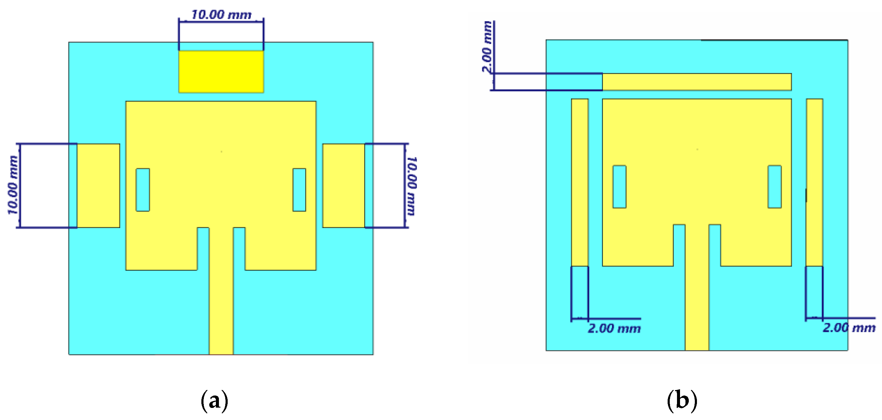
2. Antenna Design Configuration

This study presents a comprehensive comparison of two patch antennas to validate the efficacy of the proposed approach. Antenna-1 is a conventional patch antenna with slots, while Antenna-2 is a novel patch antenna with parasitic elements and slots. The introduction of parasitic elements in the conventional patch antenna can lead to an increase in antenna gain and bandwidth. Figure 1 shows the simulated and fabricated front views of both antennas. The antennas are designed using the concept of a microstrip patch antenna, with FR-4 substrate having a relative permittivity of 4.3 and a thickness of 1.6 mm, and copper with a thickness of 0.035 mm for the radiating and ground planes. Slots are implemented on the radiating patch to enable the antenna to operate at two different bands, and the concept of the inset-fed technique is used for better impedance matching. To design the proposed antenna, Equation (1) to Equation (7) from [22] were used. The width, Wp and the length, Lp of the patch are calculated using the equations as given below:
W p = c 2 f o ( ε r + 1 ) 2
Here, C = 3 × 10⁸ m/s (light speed), εr = permittivity of substrate and fo = resonant frequency (GHz).
L p = L reff 2 Δ L
where Lreff can be found using:
L reff = c 2 f o ε r e f f
Next, ground width (Wg) and ground length (lg) were calculated using:
Wg = 6h + Wp
Lg = 6h + Lp
here h = height of the substrate
The width of feed line, Wf:
Zo = [ 87 / ( ε r + 1.141 ) ) ] ln ( 5.98 h / 0.8 W f )
The length of feedline, Lf:
L f = L g L p 2
The overall antenna dimensions (unit in mm) of both antennas are identical, with Wg = 36, Lg = 35, Wp = 22.5, Lp = 20, SW = 1.5, SL = 5, Lf = 15, Wf = 2.85, PL1 = 5, PW1 = 11.5, PW3 = 5, PL3 = 20, PL2 = 5 and PW2 = 8.4. However, in Antenna-1, there are no parasitic strips. The simulated and fabricated designs of Antenna-1 and Antenna-2 are illustrated in Figure 1a,c, and Figure 1b,d, respectively.

3. Results and Discussion

3.1. Reflection Coefficient (|S11|) and Bandwidth

The reflection coefficient of the fabricated antenna was simulated using Computer Simulation Tool (CST) Microwave Studio (MWS) software version 2022 and measured using a vector network analyzer (VNA) (Agilent E5071C) under five different conditions. The measurement setup for Antenna-1 and Antenna-2 is illustrated in Figure 2a,b, respectively. Figure 2c shows the reflection coefficient plot for the simulated and obtained measurement results. For Antenna-1, the |S11| value at the desired frequency ranges was below −10 dB while resonating at 3.51 GHz with a bandwidth of 140 MHz (3.45 to 3.59 GHz). Additionally, the antenna obtained bandwidth of 150 MHz (5.85 to 6 GHz) while resonating at 5.97 GHz. In contrast, the measured results for the n77 (3.3–4.2 GHz) and n78 (3.3–3.8 GHz) bands showed the antenna operating at 3.62 GHz with a bandwidth of 100 MHz (3.59 to 3.69 GHz), and at 6.14 GHz, covering 6 GHz to 6.21 GHz (210 MHz) for the n96 band. For the proposed Antenna-2, both the simulated and measured |S11| values at the 3.3–4.2 GHz, 3.3–3.8 GHz, and 5.9–7.1 GHz bands were below −10 dB. The simulated bandwidth at 3.45 GHz was 160 MHz (3.34 to 3.49 GHz), while at 5.9 GHz, the antenna resonated at 5.87 GHz, covering a bandwidth from 5.75 GHz to 5.97 GHz (220 MHz). In measurements, the proposed antenna resonated at 3.52 GHz, covering 3.45 GHz to 3.55 GHz (100 MHz), and the antenna covered 5.97 GHz to 6.145 GHz with a bandwidth of 175 MHz, resonating at 6.0 GHz. The simulated and measured results matched well, with a small deviation attributed to the fabrication tolerance and soldering loss. Additionally, the use of SubMiniature version A (SMA) ports to excite the antenna in fabrication resulted in some insertion loss, unlike the waveguide port used in the simulation.

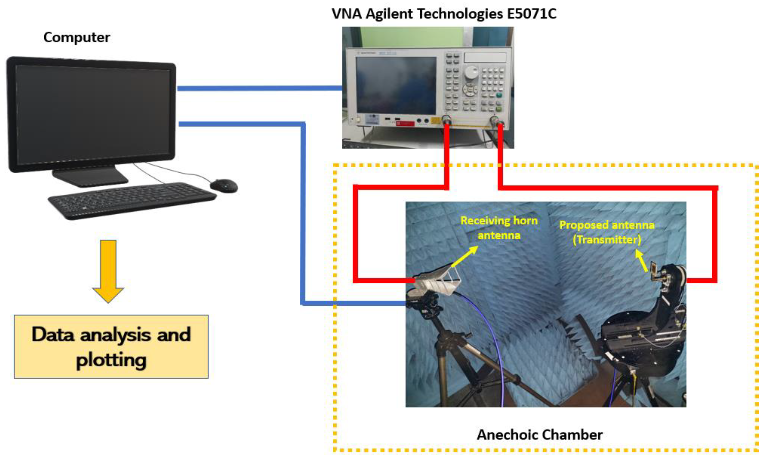
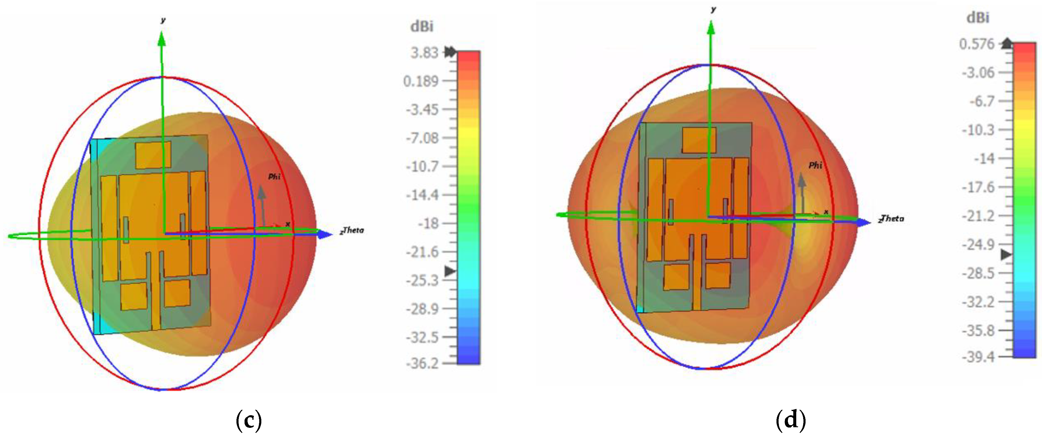
3.2. Radiation Pattern

To evaluate the performance of the proposed antenna, the radiation pattern was measured inside an anechoic chamber, as shown in Figure 3. The proposed antenna acted as the transmitting antenna, while a standard horn antenna (INFOMW LB-20200-SF) at the other end acted as the receiving antenna. The measurement was carried out by rotating (360°) azimuthally across the horizontal direction (x-direction) as shown in Figure 4. The measurement was conducted at the Advanced Communication Engineering (ACE) research lab at Universiti Malaysia Perlis (UniMAP).
The gain of Antenna-1 obtained through simulation, are shown in Figure 4a,b, respectively. It can be observed that Antenna-1 has a gain value of 2.79 dBi and 0.1 dBi at 3.45 GHz and 5.9 GHz, respectively. In contrast, Antenna-2 has a gain of 3.83 dBi and 0.576 dBi at 3.45 GHz and 5.9 GHz, respectively, as shown in Figure 4c,d. A comparison of the gain results for Antenna-1 and Antenna-2 reveals that Antenna-2 outperformed Antenna-1 significantly at 3.45 GHz and 5.9 GHz. At 3.45 GHz, the calculated enhanced gain was 40% higher for Antenna-2 than for Antenna-1, while at 5.9 GHz, the calculated enhanced gain for Antenna-2 was almost five times the gain obtained by Antenna-1. These results demonstrate the efficacy of the proposed approach in improving the gain of the proposed antenna.
Figure 5 shows the 2D polar radiation patterns of the proposed antenna. At 3.45 GHz, both the simulated and measured radiation patterns show that the antenna exhibits a strong radiation pattern towards the boresight direction, indicating a high level of directivity and gain, as illustrated in Figure 5a,b. These results are promising for the design of high-performance wireless communication systems that require directional antennas with high gain and efficiency. At 5.9 GHz, however, the simulated and measured radiation pattern is close to omnidirectional, as it is spread over a wider area, as shown in Figure 5c,d. This explains why the simulated gain at 3.45 GHz is higher than the gain at 5.9 GHz. These findings provide useful insights into the performance and suitability of the proposed antenna for 5G wireless communication systems, particularly in applications where directional antennas with high gain and efficiency are required.
Figure 6a shows the gain over frequency for Antenna-1 and Antenna-2. It can be observed that the gain at 3.45 GHz for Antenna-2 was higher than the gain for Antenna-1. However, the gain dropped drastically for Antenna-2 while the gain dropped linearly for Antenna-1. From 3.5 GHz, the gain again started to increase for Antenna −2 and it kept increasing till 5.7 GHz approximately. In the case of Antenna-1, the gain was dropping until almost 4.8 GHz and then it started increasing again until 6 GHz. At 3.6 GHz, the gain for Antenna-1 was −3.8 dBi while the gain was 3.18 dBi for Antenna-2. Subsequently, at 4.8 GHz, the gain for Antenna-1 was 0.060 dBi and the gain for Antenna-2 was −1.89 dBi. However, at 5.9 GHz, Antenna-2 achieved higher gain value of 0.576 dBi while Antenna-1 achieved 0.1 dBi. The efficiency over frequency for Antenna-1 and Antenna-2 is illustrated in Figure 6b. The efficiency of Antenna-2 at 3.45 GHz was 59% while the efficiency was 47% for Antenna-1. The efficiency dropped dramatically for Antenna-2 until 4.8 GHz approximately while the efficiency dropped constantly for Antenna-1. At 3.87 GHz, the efficiency for Antenna-1 and Antenna-2 obtained was 46% and 15.9%, respectively. However, at higher frequency onwards, the efficiency of Antenna-2 was more than the efficiency of Antenna-1 because at 5.7 GHz, the gain obtained for Antenna-2 was 36.7% while it was 22% for Antenna-1. Additionally, at 5.9 GHz, the efficiency achieved by Antenna-2 was 45% and Antenna-1 achieved 40%.

3.3. Surface Current Density

Figure 7 shows the surface current distributions of the proposed antenna for 3.45 GHz and 5.9 GHz. The surface current distribution analysis is crucial to identify the components or regions of the antenna responsible for the multi-band frequencies. At 3.45 GHz, the current intensity is more concentrated on the edges of the antenna length and the two-sided parasitic strips, as shown in Figure 7a. These regions are responsible for the antenna to resonate at the desired frequency bands. Meanwhile, for 5.9 GHz, the current intensity is less concentrated across the edges of the antenna length but more concentrated across the antenna width and upper parasitic strips, as demonstrated in Figure 7b. Therefore, these regions are responsible for the antenna to resonate at the n96 band. These results provide valuable insights into the design and optimization of multi-band antennas.

3.4. Parametric Study on Width and Length Parasitic Patch Effect

To investigate the impact of parasitic strip dimensions on the performance of the proposed dual-band microstrip patch antenna, we conducted two parametric studies. In Case-1, we studied the effect of the length of the parasitic strip, as shown in Figure 8a, on the resonating frequency, bandwidth, and gain of the antenna. In Case-2, we investigated the effect of the width of the parasitic strip, as shown in Figure 8b, on the same performance metrics. These studies provide valuable insights into the design and optimization of dual-band microstrip patch antennas.

3.4.1. |S11| and Bandwidth

Figure 9 illustrates the simulated results of varying the length and width of the parasitic strip in comparison to the finalized design of the proposed dual-band microstrip patch antenna. In Case-1, where the length of the parasitic strip was varied, the antenna resonated at 3.52 GHz with an |S11| value of −19.37 dB, with an overall bandwidth coverage from 3.45 to 3.60 GHz, which is still within the n77/n78 band. For the n96 (5.9–7.1 GHz) band, the antenna resonated at 5.92 GHz, with bandwidth coverage from 5.81 to 6.0 GHz. When the length of the parasitic strip was varied, the operating frequency of the antenna slightly shifted to lower bands in the n77/n78 band, while it shifted slightly to a higher frequency band in the n96 band. In Case-2, where the width of the parasitic strip was varied, the antenna resonated at 3.45 GHz with an |S11| value of −19.36 dB and a bandwidth value of 160 MHz (3.39 to 3.55 GHz). The resonating frequency of the antenna shifted slightly to a higher band, where it resonated at 5.93 GHz with an |S11| value of -22.9 dB and bandwidth coverage from 5.82 to 6.0 GHz.

3.4.2. Antenna Gain

We have conducted parametric studies on the proposed dual-band parasitic strip antenna to investigate the effect of reducing its length and width. For Case-1, where the length was reduced, the antenna gain decreased for both 3.45 GHz and 5.9 GHz. The gain at 3.45 GHz was 2.93 dBi, while the gain was 0.464 dBi at 5.9 GHz, as illustrated in Figure 10a,b, respectively. In contrast, for Case-2, where the width was reduced, the gain of the antenna improved. The gain values were 3.73 dBi and 0.602 dBi at 3.45 GHz and 5.9 GHz, respectively, as shown in Figure 10c,d, respectively. These results suggest that by reducing the width of the parasitic strip, the gain of the antenna can be increased for both 3.45 GHz and 5.9 GHz.
The performance comparison between Antenna-1 and the proposed antenna, Antenna-2, is summarized in Table 1, demonstrating that the proposed antenna outperforms Antenna-1 in terms of key performance metrics. Furthermore, compared to previously published works as summarized in Table 2, the proposed dual-band parasitic strip antenna is much smaller in size and exhibits a wider bandwidth and moderate gain for multiple frequency bands.

4. Conclusions

In this work, we have designed and fabricated two FR-4-based dual-band rectangular microstrip patch antennas with an inset-fed technique, operating at 3.45 GHz which falls under sub-6 GHz band and at 5.9 GHz which falls under sub-7 GHz band. One antenna, Antenna-1, is a conventional dual-band patch antenna with slots, while the other, Antenna-2, is a parasitic strip-based antenna proposed in this study. By comparing Antenna-1 and Antenna-2 in terms of bandwidth, gain, directivity, and efficiency, we have demonstrated that Antenna-2 outperforms conventional dual-band patch antennas. The implementation of parasitic strips is the key factor for the enhancement of antenna performance. Moreover, we have carried out measurements to validate the performance of the proposed parasitic strip-based dual-band microstrip patch antenna, which has a compact size of 36 × 37 mm2 and is easy to design. The proposed antenna exhibits a wider bandwidth above 150 MHz for both sub-6 GHz and sub-7 GHz bands, with a gain value of 3.83 dBi at 3.45 GHz and 0.583 dBi at 5.9 GHz. These measured and tested results have been validated by CST-MWS 2022 software-based simulations. Furthermore, parametric studies have shown that by reducing the width of the parasitic strip, the gain of the antenna can be further increased. Based on our investigations and extensive parametric study, we conclude that the proposed antenna is an excellent competitor for applications below sub-6 GHz of 5G. These findings provide valuable insights into the design and optimization of dual-band microstrip patch antennas for 5G wireless communication systems, particularly in applications where a wide range of frequency bands and high-performance characteristics are required.

Author Contributions

Conceptualization, S.K.N.; Software, M.J.; Validation, T.S. and M.H.; Resources, A.H.R.; Data curation, H.V.; Writing—review & editing, A.M.A. All authors have read and agreed to the published version of the manuscript.

Funding

This research was funded by King Saud University grant number (RSP2023R482).

Acknowledgments

Researchers Supporting Project number (RSP2023R482), King Saud University, Riyadh, Saudi Arabia.

Conflicts of Interest

The authors declare no conflict of interest.

References

  1. Azim, R.; Alam, T.; Paul, L.C.; Aktar, R.; Meaze, A.K.M.M.H.; Islam, M.T. Low Profile Multi-slotted Patch Antenna for Lower 5G Application. In Proceedings of the 2020 IEEE Region 10 Symposium (TENSYMP), Dhaka, Bangladesh, 5–7 June 2020; pp. 366–369. [Google Scholar] [CrossRef]
  2. Noor, S.K.; Ismail, A.M.; Yasin, M.N.M.; Osman, M.N.; Ramli, N. Orbital Angular Momentum Vortex Waves Generation Using Textile Antenna Array for 5G Wearable Applications. In Proceedings of the 2022 IEEE Symposium on Wireless Technology & Applications (ISWTA), Kuala Lumpur, Malaysia, 17–18 August 2022; pp. 7–12. [Google Scholar] [CrossRef]
  3. Qualcomm. Global Update on Spectrum for 4G & 5G; White Pap.; Qualcomm Inc.: San Diego, CA, USA, 2020; pp. 1–21. Available online: https://www.qualcomm.com/media/documents/files/spectrum-for-4g-and-5g.pdf (accessed on 7 May 2023).
  4. Ramli, N.; Ali, M.T.; Yusof, A.L.; Muhamud-Kayat, S.; Aziz, A.A.A. Frequency-reconfigurable stacked patch microstrip antenna using aperture-coupled technique. Int. J. Microw. Opt. Technol. 2014, 9, 199–205. [Google Scholar]
  5. Pragati; Tripathi, S.L.; Patre, S.R.; Singh, S.; Singh, S.P. Triple-band microstrip patch antenna with improved gain. In Proceedings of the 2016 International Conference on Emerging Trends in Electrical Electronics & Sustainable Energy Systems (ICETEESES), Sultanpur, India, 11–12 March 2016; pp. 106–110. [Google Scholar] [CrossRef]
  6. Tang, X.; Jiao, Y.; Li, H.; Zong, W.; Yao, Z.; Shan, F.; Li, Y.; Yue, W.; Gao, S. Ultra-Wideband Patch Antenna for Sub-6 GHz 5G Communications. In Proceedings of the 2019 International Workshop on Electromagnetics: Applications and Student Innovation Competition (iWEM), Qingdao, China, 18–20 September 2019; pp. 5–7. [Google Scholar] [CrossRef]
  7. Paul, L.C.; Das, S.C.; Rani, T.; Muyeen, S.M.; Shezan, S.A.; Ishraque, M.F. A slotted plus-shaped antenna with a DGS for 5G Sub-6 GHz/WiMAX applications. Heliyon 2022, 8, e12040. [Google Scholar] [CrossRef] [PubMed]
  8. Sree, M.F.A.; Elazeem, M.H.A.; Swelam, W. Dual Band Patch Antenna Based on Letter Slotted DGS for 5G Sub-6GHz Application. J. Phys. Conf. Ser. 2021, 2128, 012008. [Google Scholar] [CrossRef]
  9. Tütüncü, B.; Kösem, M. Substrate Analysis on the Design of Wide-Band Antenna for Sub-6 GHz 5G Communication. Wirel. Pers. Commun. 2022, 125, 1523–1535. [Google Scholar] [CrossRef] [PubMed]
  10. Al Kharusi, K.W.S.; Ramli, N.; Khan, S.; Ali, M.T.; Halim, M.H.A. Gain enhancement of rectangular microstrip patch antenna using air gap at 2.4 GHz. Int. J. Nanoelectron. Mater. 2020, 13, 211–224. [Google Scholar]
  11. Mekki, A.S.; Hamidon, M.N.; Ismail, A.; Alhawari, A.R.H. Gain Enhancement of a Microstrip Patch Antenna Using a Reflecting Layer. Int. J. Antennas Propag. 2015, 2015, 975263. [Google Scholar] [CrossRef] [Green Version]
  12. Kapoor, A.; Mishra, R.; Kapoor, A.; Kumar, P. Compact wideband-printed antenna for sub-6 GHz fifth-generation applications. Int. J. Smart Sens. Intell. Syst. 2020, 13, 1–10. [Google Scholar] [CrossRef]
  13. Kulkarni, J.; Sim, C. Wideband CPW-Fed Oval-Shaped Monopole Antenna for Wi-Fi 5 and Wi-Fi 6 Applications. Prog. Electromagn. Res. C 2021, 107, 173–182. [Google Scholar] [CrossRef]
  14. Liu, X.; Wang, H.; Yang, X.; Wang, J. Quad-Band Circular Polarized Antenna for GNSS, 5G and WIFI-6E Applications. Electronics 2022, 11, 1133. [Google Scholar] [CrossRef]
  15. Hu, Z.; Xiao, Z.; Jiang, S.; Song, R.; He, D. A Dual-Band Conformal Antenna Based on Highly Conductive. Materials 2021, 14, 5087. [Google Scholar] [CrossRef] [PubMed]
  16. Analysis, C.M. Design of a 5G Sub-6 GHz Vehicular Cellular Antenna Characteristic Mode Analysis. Sensors 2022, 22, 8862. [Google Scholar]
  17. Lawoye, T.O.; Kumar, P. A High Gain Antenna with DGS for Sub-6 GHz 5G Communications. Adv. Electromagn. 2022, 11, 41–50. [Google Scholar]
  18. Patch, A.S.D.; Array, A.; Application, W. A Simple Dual-Polarized Patch Antenna Array for Wi-Fi 6/6E Application. IEEE Trans. Antennas Propag. 2022, 70, 11143–11148. [Google Scholar]
  19. Kumar, A.; Althuwayb, A.A.; Al-hasan, M.J. Wideband Triple Resonance Patch Antenna for 5G Wi-Fi Spectrum. Prog. Electromagn. Res. Lett. 2020, 93, 89–97. [Google Scholar] [CrossRef]
  20. Sim, C.; Chen, C.-C.; Zhang, X.Y.; Lee, Y.-L.; Chiang, C.-Y. Very Small-Size Uniplanar Printed Monopole Antenna for Dual-Band WLAN Laptop Computer Applications. IEEE Trans. Antennas Propag. 2017, 65, 2916–2922. [Google Scholar] [CrossRef]
  21. Parizi, S.A.R. Bandwidth Enhancement Techniques. Trends Res. Microstrip Antennas 2017, 9–11. [Google Scholar] [CrossRef] [Green Version]
  22. Balanis, C.A. Antenna theory: A review. Proc. IEEE 1992, 80, 7–23. [Google Scholar] [CrossRef]
Figure 1. Simulated and fabricated designs of the proposed patch antennas: (a) Simulated Antenna-1, (b) Simulated Antenna-2, (c) Fabricated Antenna-1, (d) Fabricated Antenna-2.
Electronics 12 02555 g001
Figure 2. Simulated and Measured |S11| and bandwidth results (a) Antenna-1 setup (b) Antenna-2 setup (c) Comparison between Antenna-1 and Antenna-2 obtained results.
Electronics 12 02555 g002
Figure 3. Radiation pattern measurement of the proposed antenna.
Electronics 12 02555 g003
Figure 4. Simulated antenna gains (a) Antenna-1 gain at 3.45 GHz (b) Antenna-1 gain at 5.9 GHz (c) Antenna-2 gain at 3.45 GHz (d) Antenna-2 gain at 5.9 GHz.
Electronics 12 02555 g004aElectronics 12 02555 g004b
Figure 5. Proposed antenna (Antenna-2) 2D polar radiation pattern (a) Simulated 2D polar pattern at 3.45 GHz (b) Measured 2D polar pattern at 3.45 GHz (c) Simulated 2D polar pattern at 5.9 GHz (d) Measured 2D polar pattern at 5.9 GHz.
Electronics 12 02555 g005
Figure 6. Simulated results of Antenna-1 and Antenna-2 (a) Gain over frequency (b) Efficiency over frequency.
Electronics 12 02555 g006
Figure 7. Surface current density of Antenna-2 (a) 3.45 GHz (b) 5.9 GHz band.
Electronics 12 02555 g007
Figure 8. Parametric studies (a) Case-1 with reduced length (b) Case-2 with reduced width.
Electronics 12 02555 g008
Figure 9. Simulated reflection coefficient and bandwidth for Case-1 and Case-2.
Electronics 12 02555 g009
Figure 10. Effect of parasitic strip length and width on gain (a) Case-1 at 3.45 GHz (b) Case-1 at 5.9 GHz (c) Case-2 at 3.45 GHz (d) Case-2 at 5.9 GHz.
Electronics 12 02555 g010aElectronics 12 02555 g010b
Table 1. Comparison between Antenna-1 and Antenna-2.
ParametersAntenna-1Antenna-2 (Proposed)
3.45 GHz5.9 GHz3.45 GHz5.9 GHz
Bandwidth140 MHz150 MHz160 MHz220 MHz
Gain2.79 dBi0.1 dBi3.83 dBi0.576 dBi
Directivity6.08 dBi1.79 dBi5.93 dBi2.75 dBi
Efficiency47%40%59%45%
Antenna dimension36 mm × 37 mm36 mm × 37 mm
Table 2. Comparison of the proposed antenna (Antenna-2) with some of the previous works.
Ref.Frequency (GHz)Antenna Size (mm2)Bandwidth (MHz)Gain (dBi)Remark
[6]2.55, 3.5 and 4.7550 × 8029202.52, 3.05 and 4.31Antenna is bigger and does not cover n77/n78 band
[7]3.1220 × 3525602.44Single band and low gain
[8]4.53 and 4.9777 × 70.11Not reported5 and 4.57Antenna is bigger and did not cover n77/n78 and n96 band
[9]5.6552.92 × 55.561357.15Single-band only, the antenna is bigger, and the bandwidth is narrow
[10]2.480 × 8072.8377.91Single band, the antenna is bigger, and the bandwidth is narrow
[11]2.39260 × 5544.75.2Single band, the antenna is bigger and has a very narrow bandwidth
[12]3.6528 × 207002.5Single band and low gain
This work3.45 and 5.936 × 37160 and 2203.83 and 0.537Smaller in size, dual-band, wider bandwidth, and moderate gain for sub-6 GHz band but has low gain for sub-7 GHz band
Disclaimer/Publisher’s Note: The statements, opinions and data contained in all publications are solely those of the individual author(s) and contributor(s) and not of MDPI and/or the editor(s). MDPI and/or the editor(s) disclaim responsibility for any injury to people or property resulting from any ideas, methods, instructions or products referred to in the content.

