Article

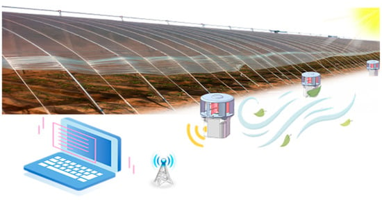
Electromechanical Properties of a Hybrid Broadband Wind Energy Harvester for Smart Agriculture Monitoring in the Loess Plateau

1
Guangdong Institute of Semiconductor Micro-Nano Manufacturing Technology, Foshan 528200, China
2
Science and Technology on Electronic Test and Measurement Laboratory, School of Instrument and Electronics, North University of China, Taiyuan 030051, China
*
Authors to whom correspondence should be addressed.
These authors contributed equally to this work.
Electronics 2023, 12(1), 34; https://doi.org/10.3390/electronics12010034
Submission received: 9 November 2022 / Revised: 12 December 2022 / Accepted: 20 December 2022 / Published: 22 December 2022
(This article belongs to the Topic Power System Protection)

Abstract

:
Wind, as a ubiquitous energy, is an important power source for intelligent monitoring systems in smart agriculture applications, and its efficient collection can greatly improve the long-term performance of monitoring systems. However, it is difficult to achieve the broadband and efficient harvesting of wind energy using the existing energy collection technology. Herein, a broadband energy conversion device (ECD), consisting of a triboelectric nanogenerator (TENG) and an electromagnetic generator (EMG), is proposed for wind energy collection under different wind speeds. The introduction of an optimized Scotch yoke mechanism greatly improves the utilization of wind energy by the TENG, thus reducing energy dissipation. Moreover, the addition of a deflector into the fan greatly reduces the start-up wind speed and improves the ability of the device to capture breeze energy. By doping multi-walled carbon nanotubes, the output voltage and current of the TENG can be improved by 108.89% and 116.61%, respectively. Furthermore, the adopted all-directional conductive foam can greatly prolong the service life of the ECD. The peak power of the ECD is 68.49 mW at 9.6 m/s, with the EMG and TENG producing approximately 64.80 mW and 3.69 mW, respectively. The proposed ECD provides a new technical strategy for the practical application of wind energy harvesters.

Graphical Abstract

1. Introduction

In the Loess Plateau region of China, crops are affected by monsoon and drought, resulting in some crops being unsuitable for planting or reducing their overall yield. Agricultural modernization plays an indispensable role in the modern industrial system. The accurate and real-time sensing of agricultural information is an important guarantee for improving the comprehensive agricultural production capacity. Traditional agricultural information sensing methods usually exhibit the typical shortcomings of fixed monitoring and a small number of sampling points [1]. The application of the Internet of things (IoT) technology, connecting multi-sensing nodes to agricultural monitoring, effectively improves the accuracy of agricultural information sensing. However, traditional IoT nodes rely on external power, which not only makes replacement, charging, and maintenance inconvenient, but also results in environmental pollution [2,3,4,5,6,7,8,9]. Therefore, collecting renewable energy, including solar energy [10,11], wind energy [12,13], raindrop energy [14], and blue energy [15,16], to power these low-power electronic devices through energy management circuits is of great significance in dealing with energy shortages that accompany the development of economies [17]. Among renewable energy sources, wind energy has the advantages of wide distribution, convenient collection, and independence from weather conditions. Thus, collecting wind energy is considered an ideal solution for providing green energy for self-powered sensor nodes [18,19,20].
With the development of sustainable energy technologies, piezoelectric nanogenerators (PENG) [21,22], electromagnetic generators (EMG) [23,24,25], and triboelectric nanogenerators (TENG) [26,27], coupled with the triboelectric effect and electrostatic induction, have become good strategies for collecting distributed wind energy. Among these, TENGs exhibit high voltages and low current densities, as well as good performance under low-frequency motion [19]. In contrast, EMGs usually exhibit excellent current output characteristics, especially in the high-frequency response range [28]. Therefore, most researchers combine TENGs and EMGs to harvest a wider range of wind energy in order to achieve their complementary advantages and obtain higher current and voltage outputs [19,29,30]. However, in a large number of studies of composite energy harvesters based on TENGs and EMGs, the design of the TENG often uses relative sliding or rolling between friction electrode pairs to achieve wind energy capture [31,32,33,34]. Such a design will generate continuous friction between the friction layers, so that a large amount of energy is dissipated in the form of heat energy [35]. If operated over a long period of time, excessive wear and tear of the device may occur, resulting in a significant reduction in output performance [36,37]. By converting the rotating motion generated by wind energy excitation into reciprocating linear motion, the problem of low energy exchange efficiency in the contact separation mode of the TENG can be effectively reduced [38,39,40,41]. In addition, due to the randomness and instability of wind, especially for the Loess Plateau region, achieving a wide wind speed response range is also an important technical means to improve the performance of wind energy harvesting. However, most researchers focus on the optimization of the structure and materials of these composite energy harvesting devices, and only a few have focused on the improvement and optimization of the wind turbine’s structure [33,41,42,43], making it impossible to fully collect and widely utilize distributed wind energy. Therefore, optimizing and improving the composite energy harvesting device from the aspects of structure, material, and wind turbine design is an effective means to achieve highly efficient wind energy collection.
Herein, we propose an energy conversion device (ECD) made of an elastic contact-array mode TENG and an EMG for collecting wind energy. The TENG adopts an optimized Scotch yoke mechanism, which effectively improves the working contact separation frequency between the friction pairs and enhances the energy conversion efficiency. In addition, the fan, designed with an added deflector, greatly reduces the start-up wind speed of the ECD and improves the ability to capture breeze energy. Moreover, thanks to the introduced surface-modified and multi-walled carbon nanotube (MWCNT) doping, the friction effect and charge accumulation property of the silicone rubber used have been effectively improved. Furthermore, the use of elastic electrodes (conductive foam) can effectively buffer the impact between the friction materials and prolong their service life. As a result of the optimized TENG material, the introduction of a wind turbine with a deflector, and the integration of a TENG and an EMG, the ECD can efficiently collect wind energy in real time to power unattended wireless sensing nodes. This study provides a potential technical path for self-powered sensors to monitor environmental parameters in smart agriculture applications.

2. Materials and Methods

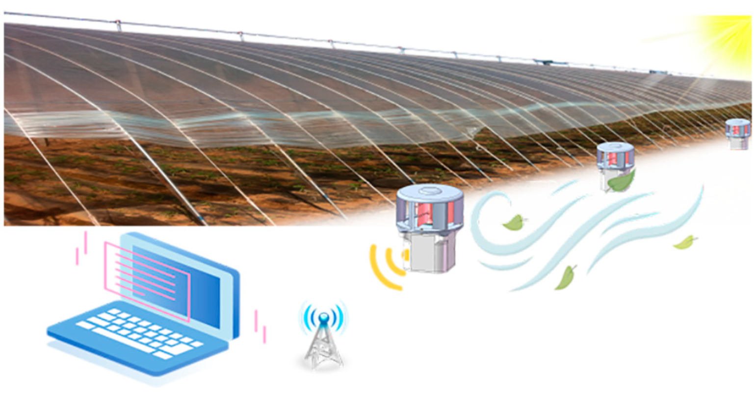
2.1. Materials and Fabrication of the ECD

The base and curing agent (1:1 volume ratio) of silicone rubber (Ecoflex 00-30) were fully mixed in a beaker, and then the MWCNT (3% weight ratio) was added to the mixed liquid silicone rubber. After being thoroughly stirred and mixed, the composite silicone rubber solution was coated in a Polytetrafluoroethylene (PTFE) mold with sandpaper and cured at room temperature for 24 h, and a soft negative triboelectric layer was obtained. In addition, the positive triboelectric layer, made of metal conductive sponge, was pasted on the fixed inner wall of the device.
The copper coils in the EMG unit exhibited the following properties: coil diameter of 15 mm, thickness of 5 mm, copper wire diameter of 0.1 mm, and 3000 coil turns. Eight NdFeB-N35 magnets (diameter: 15 mm; thickness: 5 mm) with high magnetic field strength were fixed in the rotor disk in a circular array with interlacing polarity, allowing it to rotate with the disk to make the coil cut the magnetic induction line.

2.2. Measurement System

In the experiment, a blower (YR412) was used as the wind source, and the wind speed at six different positions was calibrated by an anemometer (TASI TA8164). To visualize the output performance of the ECD, the voltage and short-circuit current were measured with a digital oscilloscope (Tektronix MSO2024B) and a Keithley 6514 electrometer, respectively.

3. Design and Working Principle of the ECD

The designed ECD mainly includes a wind energy capture unit and a hybrid power generation unit consisted of TENG and EMG. The whole shell, rotor and stator structures were prepared through 3D printing technology. Through the simulation analysis of electric field strength and magnetic field strengths, as well as the comparison of output performance, the structure and material of ECD were optimized to achieve the double enhancement of output performance.

3.1. The Structure of ECD

The detailed structural design of the ECD is shown in Figure 1a. The ECD consists of two parts: the wind energy capture unit and the power generation unit. The upper part of the device is a wind energy capture unit that collects wind energy and provides rotating torque for the generator unit. The TENG consists of friction layers, the optimized Scotch yoke structure, and an all-directional conductive sponge electrode, while the EMG consists of the highest-performance NdFeB35 magnets and multi-copper coils connected in a series.
The all-directional conductive sponge and modified silicone rubber constitute the friction layer, with positive and negative polarity; the preparation of the modified silicone rubber is shown in Figure 1b. Furthering the research on silicone rubber, this study mainly improves the output performance of TENG from two aspects. On the one hand, the silicone rubber was doped with MWCNT powder to increase its dielectric constant. On the other hand, the microstructure of the modified silicone rubber surface increases its effective contact area with the conductive foam. A picture of the modified silicone rubber is shown in Figure 1c.
Wind capture devices convert wind energy into power to drive triboelectric-electromagnetic power generation device. Figure 1d presents the optimized Scotch yoke structure. The eccentric shaft rotation drives the rotation of the EMG and the reciprocating movement of the TENG, which realizes the conversion from wind energy to electric energy. Based on the local degree of freedom theory in mechanical principles, an eccentric shaft is installed with deep groove ball bearings to effectively reduce the friction between the relative moving parts and prevent the sliding parts and eccentric shaft from becoming stuck due to impact during the contact separation process. Furthermore, in order to reduce friction loss, steel balls were embedded in the grooves of the fixed parts, which converts sliding friction into rolling friction. As shown in Figure 1e, the conductive sponge is pasted onto the inner wall of the device as a positive friction material and an electrode layer of the TENG. Figure 1f shows the overall structural design and layout of the EMG. The NdFeB35 magnets, with strong magnetic induction densities, were installed on the disk in a polarity-interleaved manner, and multiple coils were installed in a series. Figure 1g shows the overall assembly diagram of the ECD. The components that make up the ECD are fixed using standard connections, resulting in reliable structural stability and good sealing performance, especially in harsh environments. The detailed components of the ECD and the specific process of preparing the modified silicone rubber can be seen in Figures S1 and S2.

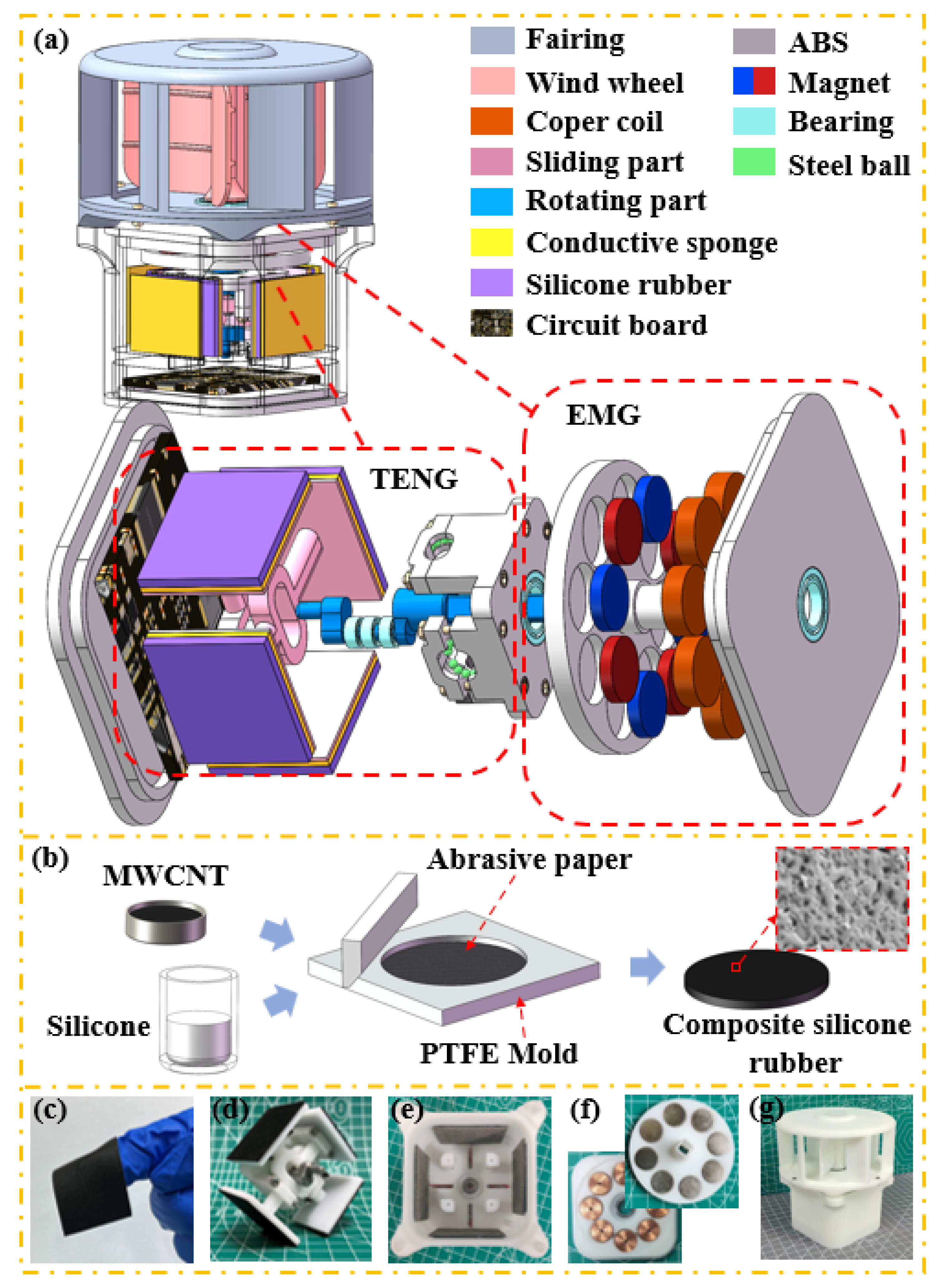
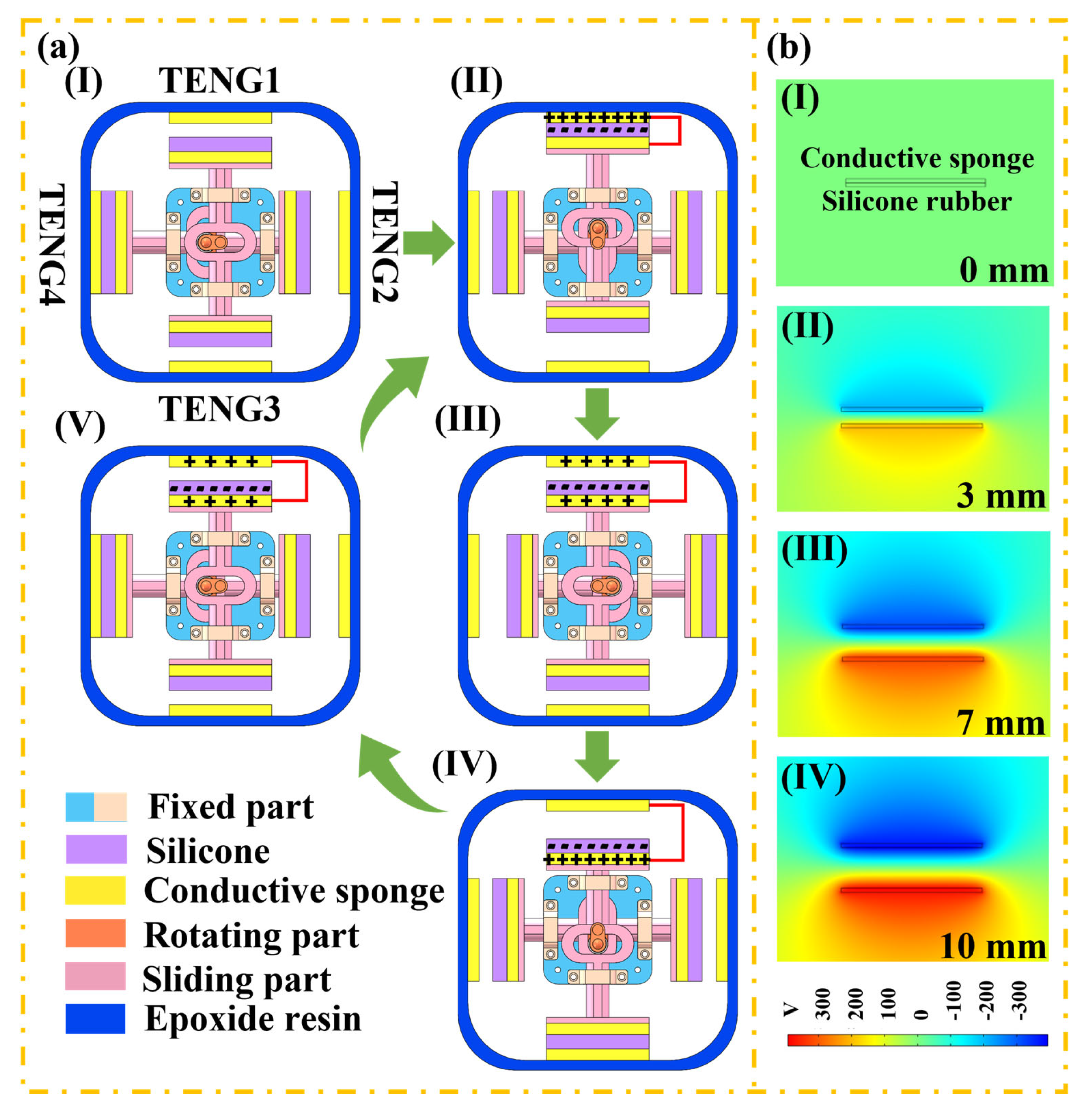
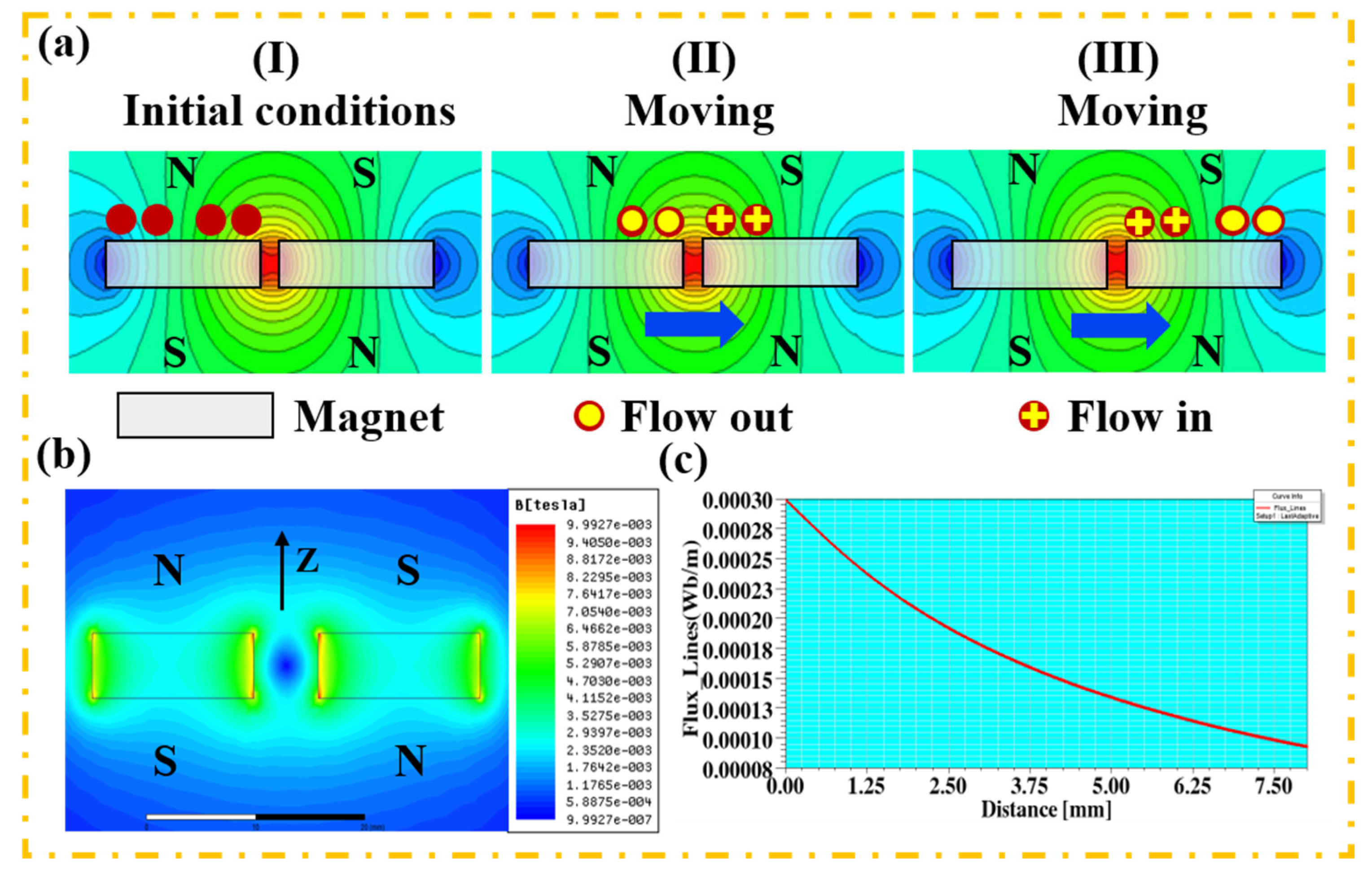
3.2. The Working Principle of the ECD

Under different wind speeds, the ECD can generates voltage and current pulse signals of different frequencies and amplitudes, generating power and enabling wind monitoring. Figure 2a illustrates how the TENG works. Taking TENG1 as the object of study, at the initial state (stage I), the conductive sponge (as the positive friction layer) and the composite silicone rubber (as the negative friction layer) are separated by a certain distance, and there is no charge generated on the surface of the conductive sponge and the composite silicone rubber. Therefore, no potential difference occurred.
At stage II, under the action of external force, the eccentric axis with the bearings rotates clockwise so that the two friction layers with opposite polarities come into contact and generate friction. Due to the triboelectric effect, equal amounts of opposite polarity charges are generated on the surfaces of the two friction layers. The eccentric axis with the bearings continues to rotate clockwise. At stage III, the positive and negative friction layers gradually separate from each other, and electrons are retained on the film’s surface. During the relative separation of the two electrodes, the potential difference will be generated. When the separation distance is increased to the maximum, the output voltage of TENG1 reaches saturation. Subsequently, when the two friction layers gradually become closer, the potential between the two electrodes steadily disappears with the decrease in their separation. At the same time, the open circuit voltage (Voc) gradually decreases from the peak level. When sufficient contact occurs between the friction layers, the voltage drops to zero, continuing to prepare for the next cycle. The working principle of the other three TENGs is the same as that of TENG1.
In order to illustrate the working principle of TENG more clearly, the potential distribution between two triboelectric materials was simulated using COMSOL Multiphysics 5.6, as depicted in Figure 3a. According to the change in distance between the two triboelectric materials, the simulation process is divided into four processes. From the simulation results, it can be seen that the electrical potential of the friction surface improves with the increase in the distance between the surfaces.
Figure 3a presents the working principle of the EMG. Based on the magnetoelectric effect [29], when the coil conductor in the closed loop is moved to cut the magnetic inductance line, an induced current is generated. In the initial state (stage I), there is no relative motion between the coil and magnet, and most of the magnetic induction lines pass through the coil. However, because the magnetic flux in the coil is unchanged, no induced current will be generated. When the disk embedded in the magnet rotates, the magnetic induction line passing through the coil gradually decreases, and the induced current is generated in the closed loop (stage II). With the disk continuing to rotate, the number of magnetic induction lines passing through the coil gradually increases, generating an induced current in the opposite direction of the loop (stage III). In addition, the distribution trend of the magnet’s magnetic field strength is analyzed using MAXWELL 16.0 software (Figure 3b). Moreover, in order to ensure the excellent output performance of the EMG, the relationship between the linear density of magnetic induction and the longitudinal distance of the magnet is simulated. From Figure 3c, it can be seen that the farther away the coil is from the magnet, the smaller the magnetic density. Therefore, the smaller the distance between the coil and the magnet, the better.

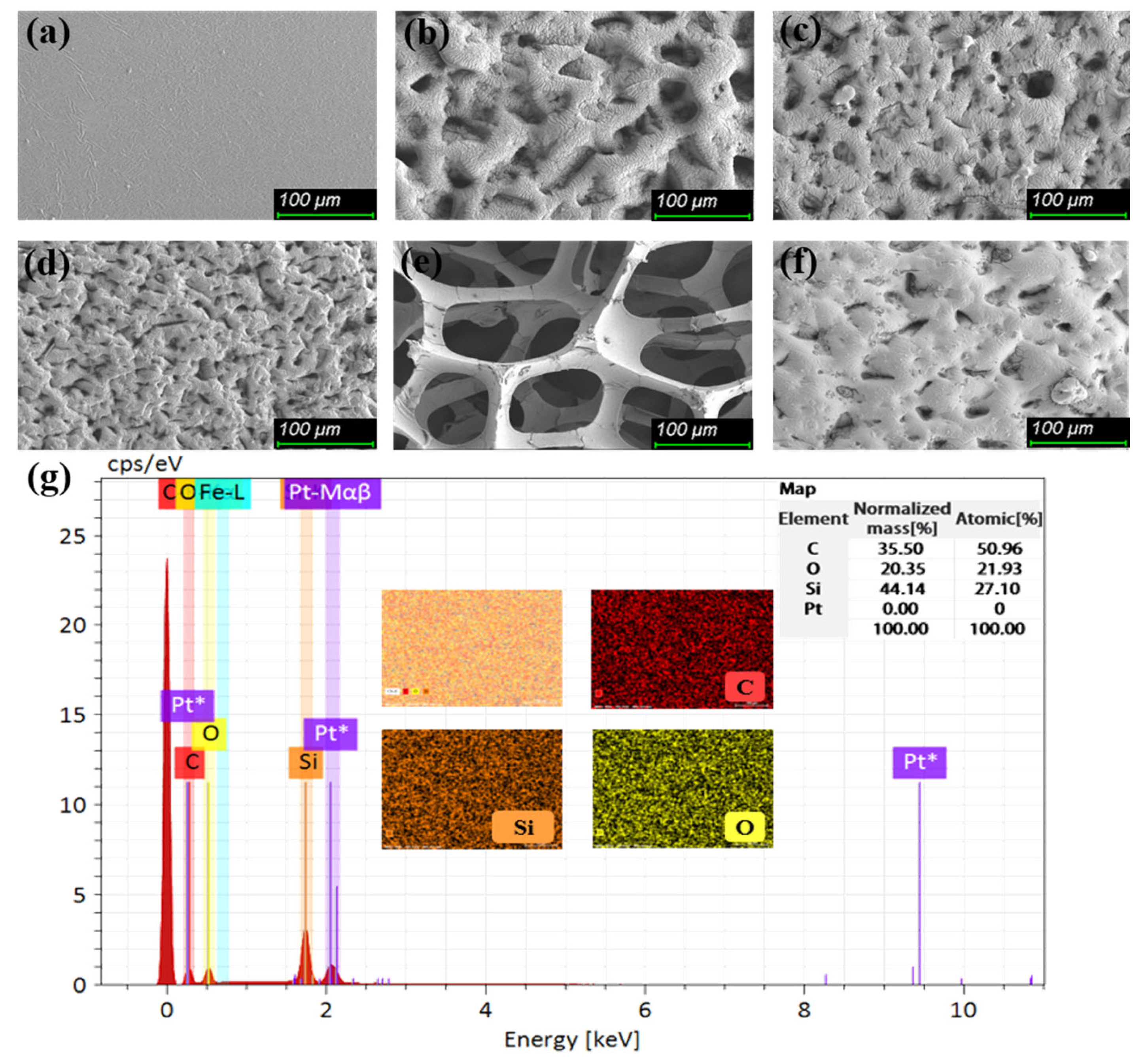
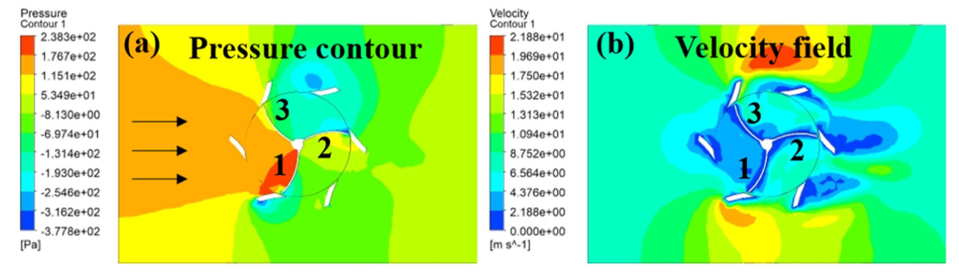
3.3. Material and Structural Optimization of the ECD

In order to improve the output performance and carrying capacity of the ECD, MWCNT doping and surface roughness modification were carried out on silicone rubber. The microscopic morphologies of composite silicone rubber with different roughnesses and the conductive sponge were observed with a scanning electron microscope (SEM, SU8020, Hitachi). The microstructures were prepared for the film using sandpaper templates of different grit sizes, resulting in different concave and convex structures, as shown in Figure 4a–d. It is worth noting that the larger the grit size of the sandpaper template, the greater the density of the concave and convex structures on the surface of the film. When the grit size of the sandpaper template is 320, the concave and convex structure on the surface of the film presents a large and sparse morphology. As the particle size of the sandpaper gradually increases, the microstructure on the surface of the film takes on a small and dense form. The composition of modified silicone rubber containing 3% MWCNT was analyzed using an EDS test (Figure 4g). The composite silicone rubber is mainly composed of C, Si, and O. It is clear to see that the MWCNT is evenly dispersed in the silicone rubber. Figure 4e shows the surface topography of the conductive sponge, which has an omnidirectional elastic structure.
The output performance of different proportions of composite silicone rubber and MWCNT was studied. The thickness and diameter of the composite silicone rubber are approximately 0.7 mm and 40 mm, respectively, and the contact separation is achieved by a very reliable bench with an operating frequency of 2 Hz. As can be seen from Figure 5a,b, the Voc of the film increases with the increase in the doping concentration. When the concentration exceeds 3%, the Voc begins to decrease. At the same time, the short-circuit current (Isc) shows the same trend, because the increase in the dielectric constant will help to enhance the charge transfer between the friction layers [42]. Therefore, MWCNT uniformly dispersed in the rubber can improve its dielectric constant, thereby significantly improving the output of the TENG. However, with the increase in the MWCNT doping concentration, the effective friction area decreases, which leads to a reduction in the triboelectric output performance of the composite silicone rubber. Based on this finding, the optimum MWCNT concentration of 3% was selected for further experiments. It can be seen that the peak-to-peak voltage of the TENG reaches 376 V, and the peak-to-peak current of the TENG is 5.96 μA. Compared with those of the undoped silicone rubber, these values are increased by 108.89% and 116.61%, respectively.
To verify the effect of the composite silicone rubber’s surface roughness on the TENG’s performance, samples of silicone rubber doped with 3% MWCNT, with different roughnesses, were also studied. They were placed on a workbench with a contact separation frequency of 2 Hz. Figure 5c,d shows the effect of the different roughnesses on the electrical outputs of the TENG. The output performance of the modified silicone rubber with the surface roughness treatment has clearly been improved compared to the modified silicone rubber with no surface treatment. This is because the surface modification of the film greatly increases the effective contact area, which improves the TENG’s output performance [43]. It can be seen from the figure that with the increase in the sandpaper’s grit size, the output performance of the TENG exhibits an obvious inflection point. When the grit size of the sandpaper ranges from 0 to 500 CW, the output performance of TENG shows an upward trend. With the increase in the grit size of the sandpaper template, the density of the concave and convex structures on the surface of the film increases, which helps to improve effective contact area and enhances the output performance of TENG. However, when the grit size of the sandpaper is gradually greater than 500 CW, the microstructure size of the film surface becomes smaller and the surface is smoother, which weakens the effective contact area and friction effect between the films, thus reducing the output performance [44]. At the sandpaper grit size of 500, the peak-to-peak voltage and current of the TENG are 532 V and 7.79 μA, respectively, reaching the maximum value. Compared with those of untreated composite silicone rubber, the peak-to-peak voltage and current of the TENG increased by 44.57% and 32.03%, respectively.
Finally, the durability and stability of the doped and surface-treated silicone rubber films were also tested. The output performance of the TENG using both films was recorded by a dataset containing multiple contact separation cycles (Figure 5e,f). The experimental results showed that the overall output performance did not change significantly after 12 h of operation. The SEM images in Figure 4f show that the surface microstructure of the film is only slightly deformed, which indicates the excellent durability and stability of the TENG.
The design of the wind capture unit was based on mechanical design theory. It was modeled in SolidWorks 2018 software and analyzed using Ansys Fluent 2021 R1 software. In the fluid–structure interaction analysis, we set the initial condition of the wind speed to 8 m/s and the wind direction was horizontal to the left (as shown by the arrow in Figure 6a. Figure 6a presents the relative pressure distribution of the device in the flow field. According to the figure, the pressure difference between the surface and back of blade 1 was large, while the pressure differences between blades 2 and 3 were relatively smaller. At that moment, the pressure difference of the blade provided the reversing torque for the wind wheel. However, due to the existence of the guide blade, the pressure difference decreased, and the reversing torque for the wind wheel was also smaller. The differential pressure of the vane is the main factor affecting its rotation and torque. The flow-field velocity distribution around the blades is shown in Figure 4b. The guide blade optimized the flow field to a certain extent, resulting in the increase in the wind speed acting on the blade in the windward region of the wind wheel. In addition, because of the shielding effect of the guide blade, when the blade on the wind wheel was on the leeward side, the wind speed acting on the back of the blade was greatly reduced. Therefore, the deflector improved the wind turbine’s range of adaptation to wind speed and the efficiency of the wind turbine and played a certain protective role that prevented the wind turbine from becoming stuck on external objects.

4. Results and Discussion

To better characterize the output performance of ECDs, the electrical output characteristics and charging performance of the TENG and EMG were tested under different simulated wind speeds. The experiments regarding driving temperature, humidity, and light intensity sensor stability further confirmed the excellent power supply ability of ECD.

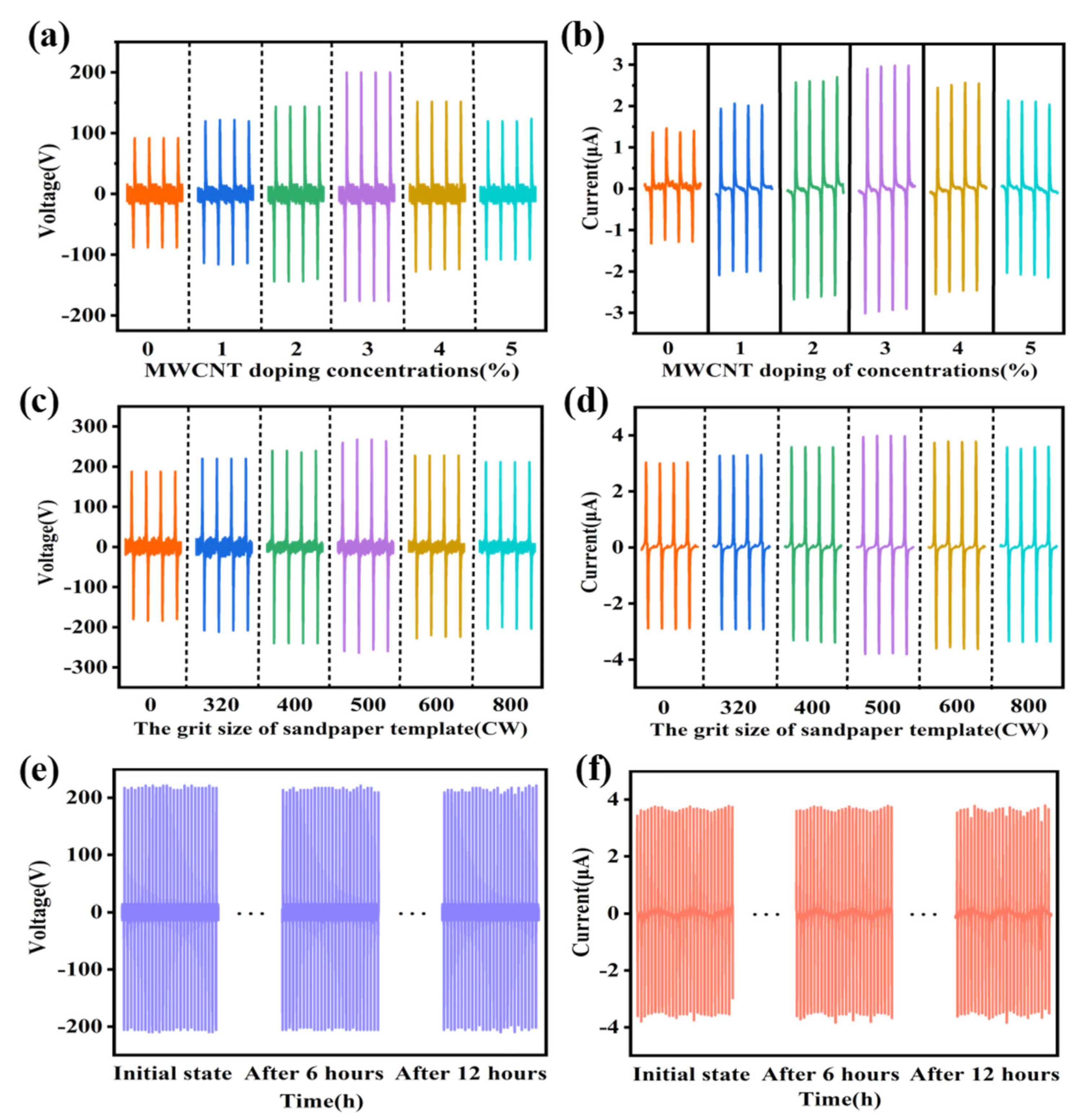
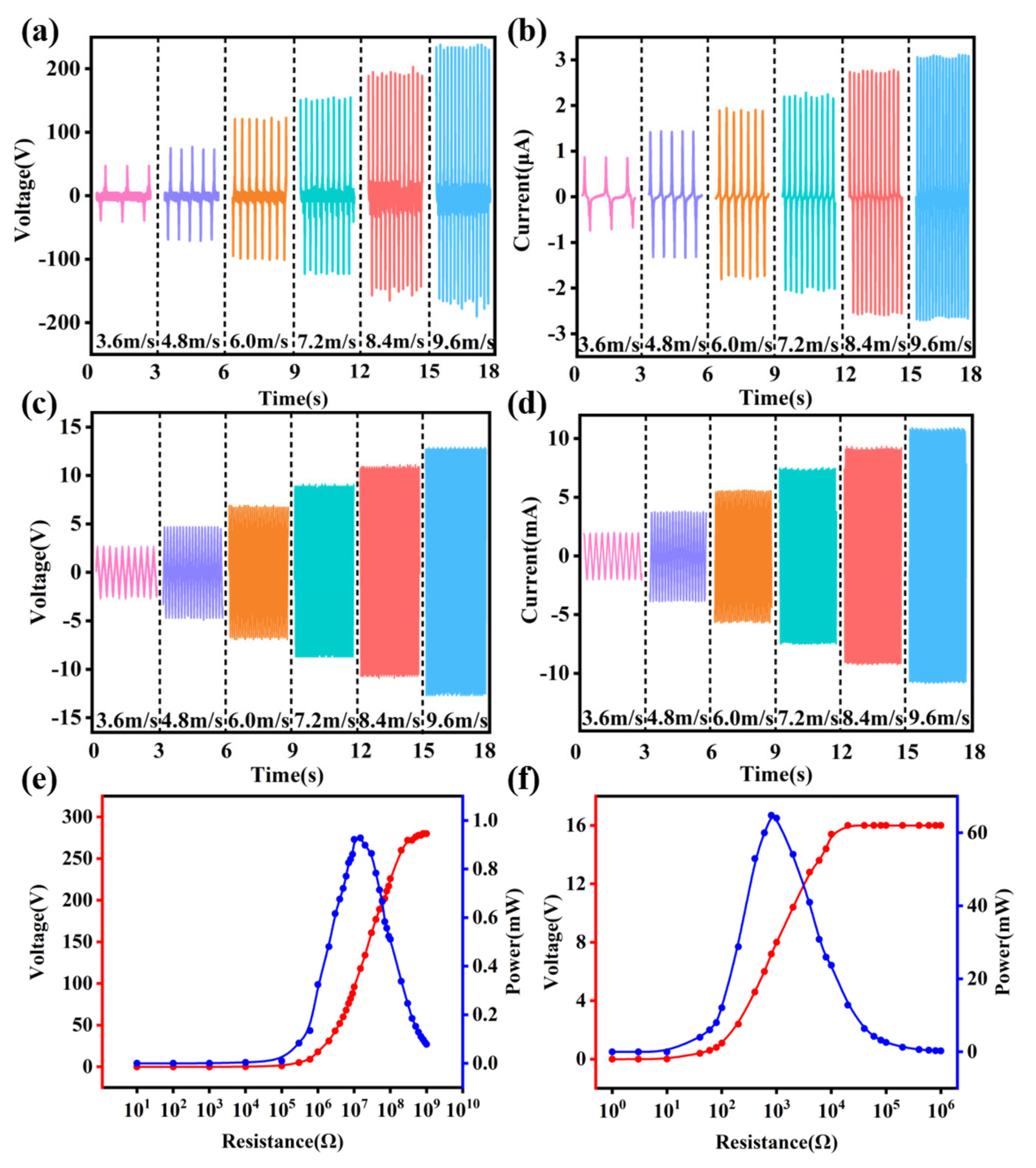
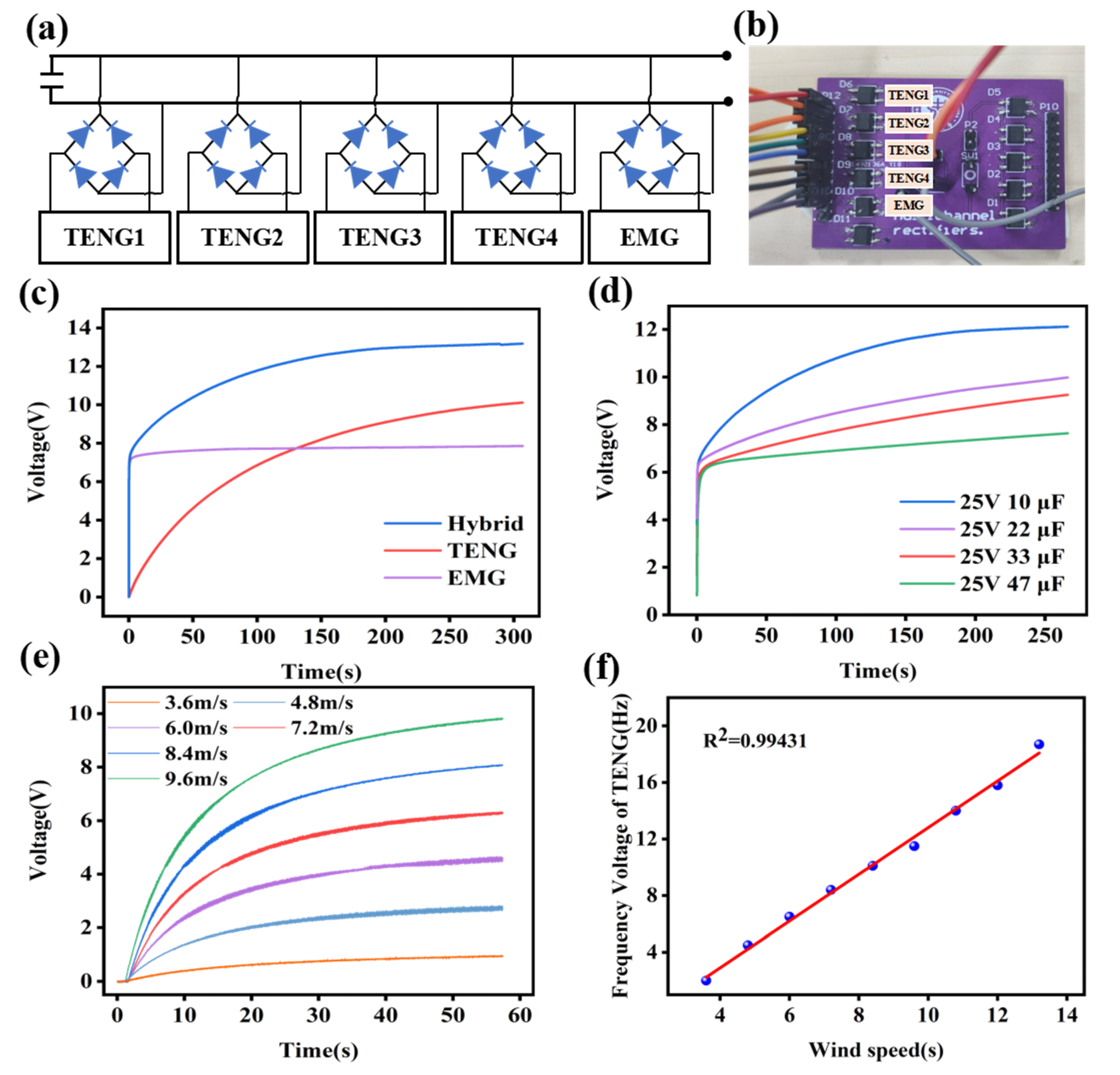
4.1. Output Characterization of the ECD

Figure 7 depicts the output performance of the TENG and EMG corresponding to different wind speeds. For TENG1, the Voc and Isc increased with increasing wind speed. As the wind speed gradually increased from 3.6 m/s to 9.6 m/s, TENG1’s Voc increased accordingly from 92 V to 440 V, and its Isc increased from 1.8 μA to 6.2 μA. The results show that the Voc and Isc of the other three TENG power generation units show the same growth trend. This is because, with the increase in wind speed, the separation frequency of the friction layers continues to increase, which in turn accelerates the charge transfer speed and increases the output of the TENG. The high-speed rotation of the fan blade gives the slider a certain inertia during contact separation, which increases the impact force between friction layers, resulting in the continuous increase in Voc. For the EMG, Faraday’s law of electromagnetic induction states that the greater the speed at which the coil cuts the magnetic induction line, the greater the induced current. At the same experimental wind speed as that used for the TENG, the Voc of EMG increased from 4.4 to 24.4 V, and its Isc increased from 2.9 to 10.1 mA.
In addition, the relationships between the output voltage and different external load resistance of the TENG and EMG at a wind speed of 9.6 m/s were tested. After sampling multiple sets of data, the output power under different loads is calculated by P = U2/R to fit the curve. According to the experimental results, when the resistance value of the external load is close to the internal resistance of the TENG about 1.5 × 10⁷ Ω, the output power of the four TENGs reaches the maximum, which is 0.91 mW, 0.93 mW, 0.92 mW, and 0.90 mW, respectively. The detailed chart data of TENG2, TENG3, and TENG4 can be found in Figure S3. The output power trend of the EMG is similar to that of the TENG. As the external resistance increases to 800 Ω, the EMG reaches a maximum output power of 64.8 mW. Based on the above results, it is concluded that the TENG and EMG have significantly different output characteristics for energy harvesting. The TENG generates a large voltage and a small current while the EMG outputs a large current and a low voltage.
Figure 8a,b show the physical and schematic diagrams, respectively, of the rectifier circuit of the ECD. The alternating current generated by the ECD passes through a multi-channel rectifier circuit and is connected in parallel to the energy storage capacitor. The ability of each generating unit of the ECD and their combination to charge the capacitor was tested at a wind speed of 7.2 m/s.
Figure 8c shows that the EMG charges the generated power into the capacitor for a short period of time and keeps the power constant, while the charging speed of the TENG is relatively slow, but the charging voltage is higher. Therefore, the combination of the TENG and the EMG can integrate their complementary advantages to improve charging efficiency. Figure 8d depicts the charging performance of the ECD for different capacitors. It can be seen that the smaller the capacity of the capacitor, the more energy is stored. Figure 8e shows the output comparison of the ECD charging a 4.7 mF capacitor at different wind speeds. The charging curves indicate that the ECD can charge capacitors at lower speeds, and the faster the rotation speed, the better the ECD’s charging capability.
Finally, the TENG generates an alternating current that monitors wind speed through the frequency of the waveform. When the rotating parts rotate once, each generating unit generates one alternating current, and the whole unit generates four alternating currents. Therefore, a corresponding linear relationship exists between the AC voltage frequency of TENG and the wind speed. As can be seen from Figure 8f, when the wind speed increases from 3.6 m/s to 13.2 m/s, the corresponding output frequency increases from 2.8 Hz to 18.6 Hz. The presence of a linear fit of up to 0.99431 gives the device the prospect of rotational speed and wind speed detection.

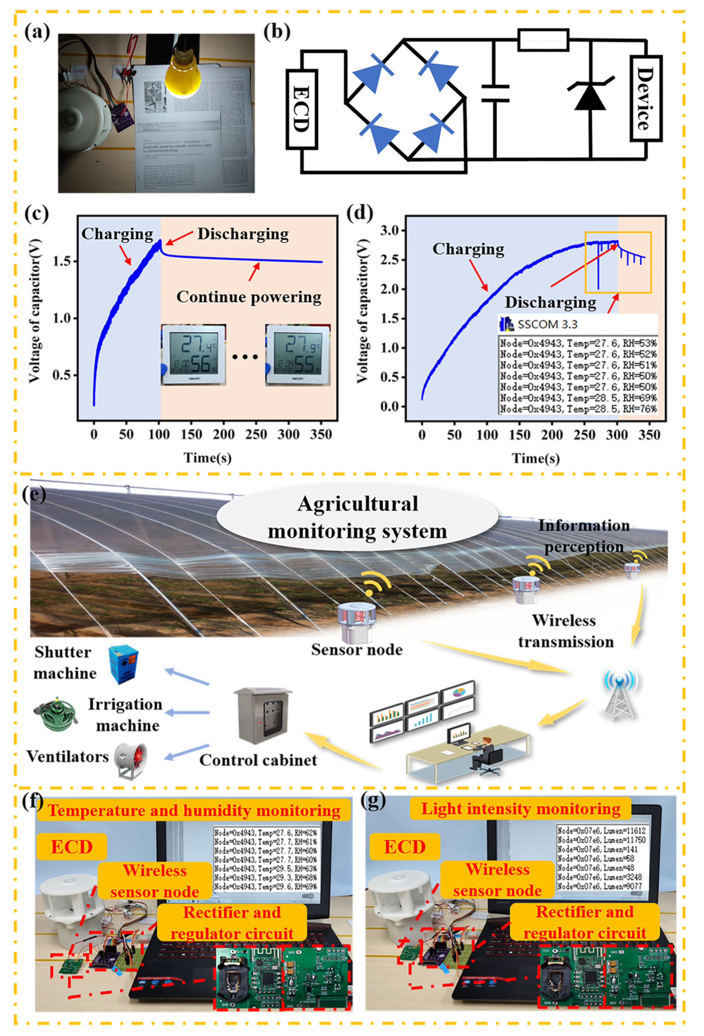
4.2. Device Application

The hybrid ECD can indirectly convert wind energy into electrical energy as a power source for small electronic devices and wireless sensing nodes. As is shown in Figure 9a, in the case of power shortage, the ECD can power a 5 W energy-saving lamp for reading or for use as an emergency lamp.
In Figure 9b, the ECD and the capacitor (6 mF ) are connected by a full-wave rectifier to power the devices. Furthermore, in order to prevent the voltage of the charging capacitor from being too large and damaging the small electronic gadgets, a voltage regulator diode (1 W, 3.3 V) and a resistor (68 Ω) are connected in parallel to supply power to the electronic equipment to achieve a voltage-stabilizing effect. Owing to the excellent output performance of the ECD, a self-powered temperature/humidity device can work continuously by harvesting energy from the wind, as presented in Figure 9c. In addition, Figure 9d shows that the collected wind energy can be stored in a 6 mF capacitor and successfully drive a temperature and humidity sensor node.
Figure 9e indicates that the ECD provides a power supply for sensor nodes to realize the real-time monitoring of the crop growth environment in agriculture and greenhouse planting. As shown in Figure 9f,g, the ECD can be integrated with a microprocessor chip to control temperature, humidity, and light intensity sensors. In this application, a 6 mf capacitor was selected to store the energy generated by the hybrid ECD, serving as the power supply of the micro-system.
For the Loess Plateau area, with its low precipitation, large temperature differences, and obvious seasonal changes in wind direction and wind power, the designed ECD based on the optimized Scotch yoke mechanism, with varying contact-separation frequencies and introduced deflectors, successfully optimizes the flow field and can effectively collect a wide range of wind energy, storing it in order to power IoT sensing nodes. In addition, the excellent charging performance of the ECD and its ability to stably supply power to temperature, humidity, and light intensity sensors validates its use for intelligent agricultural monitoring to supply power to wireless sensor nodes. Furthermore, precise strategies can be implemented based on real-time monitoring data collected by environmental sensors and crop growth needs. Therefore, the design of the ECD with a high output performance and wide wind speed response range is of practical significance for dealing with the impact of climate change on agriculture, especially in the Loess Plateau region.

5. Conclusions

In summary, a novel triboelectric-electromagnetic hybrid ECD based on the elastic vertical contact-separation mode was proposed. The ECD integrates a TENG with a high conversion efficiency at a low wind speed and an EMG with excellent performance at a high wind speed, effectively realizing broadband wind energy collection. The optimized Scotch yoke mechanism greatly improves the working efficiency of the TENG and reduces the energy loss. In addition, the introduction of deflectors to optimize the flow field of the wind turbine not only improves the starting characteristics of wind turbines, but also increases their efficiency. The output voltage and current of the TENG can be increased by 108.89% and 116.61%, respectively, by MWCNT doping. At the same time, the omnidirectional conductive foam adopted as the electrode and frictional material greatly extends the service life of the ECD and ensures its good stability. Based on the optimization of the structure and materials, the maximum output power of the ECD can reach 68.49 mW during strong winds, which makes it possible to continuously supply power to the sensing nodes used for agricultural monitoring located in the Loess Plateau. This study provides a new technical strategy for the practical application of wind energy harvesters in self-powered wireless monitoring systems.

Supplementary Materials

The following supporting information can be downloaded at: https://www.mdpi.com/article/10.3390/electronics12010034/s1, schematic diagram of the WEH components: (a–c) wind wheel, (d) top cover, (e) disk, (f) shell, (g, h) sliding base, (i) sliding parts, (j, k) eccentric shaft, (l) steel ball, (m) bottom cover, (n) ball bearing, (o) screws and nuts; s2, process for preparing composite silicone rubber: (a) pour appropriate amount of silicone into beaker, (b) add a certain proportion of MWCNT powder to beaker, (c) stir for 1 h, (d) add curing agent, (e) stir again, (f) coat the stirred mixture on the PTFE-mold with sandpaper. (g) The composite silicone rubber was prepared after 12 h of rest at room temperature; s3, the output performance of TENG2, TENG3, and TENG4 at different wind speeds: (a,d,g) the Voc of TENG2, TENG3, and TENG4; (b,e,h) the Isc of TENG2, TENG3, and TENG4; (c,f,i) the output power of TENG2, TENG3, and TENG4 at a wind speed of 7.2 m/s; Video s1, wind speed calibration and minimum starting wind speed experiment; Video s2, the ECD light energy-saving lamp; Video s3, the ECD power for wireless sensor nodes.

Author Contributions

Conceptualization, L.H.; methodology, J.S.; validation, B.W.; formal analysis, Z.D.; investigation, J.S.; data curation, Z.D.; writing—original draft preparation, L.H.; writing—review and editing, H.W.; visualization, B.W.; supervision, J.H. All authors have read and agreed to the published version of the manuscript.

Funding

This research was funded by the Key Research and Development Project of Shanxi Province, grant number 202102040201007.

Conflicts of Interest

The authors declare no conflict of interest.

References

  1. Reba, M.; Seto, K.C. A systematic review and assessment of algorithms to detect, characterize, and monitor urban land change. Remote Sens. Environ. 2020, 242, 111739. [Google Scholar] [CrossRef]
  2. Liu, K.; Kong, B.; Liu, W.; Sun, Y.; Song, M.-S.; Chen, J.; Liu, Y.; Lin, D.; Pei, A.; Cui, Y. Stretchable lithium metal anode with improved mechanical and electrochemical cycling stability. Joule 2018, 2, 1857–1865. [Google Scholar] [CrossRef] [Green Version]
  3. Wan, J.; Xie, J.; Kong, X.; Liu, Z.; Liu, K.; Shi, F.; Pei, A.; Chen, H.; Chen, W.; Chen, J.; et al. Ultrathin, flexible, solid polymer composite electrolyte enabled with aligned nanoporous host for lithium batteries. Nat. Nanotechnol. 2019, 14, 705–711. [Google Scholar] [CrossRef] [PubMed]
  4. Sun, W.; Xiao, L.; Wu, X. Facile synthesis of nio nanocubes for photocatalysts and supercapacitor electrodes. J. Alloy. Compd. 2019, 772, 465–471. [Google Scholar] [CrossRef]
  5. Liu, S.A.; Li, Z.; Zhao, K.; Hao, M.; Zhang, Z.; Li, L.; Zhang, Y.; Zhang, W. A facile hydrothemal synthesis of MoS2@Co3S4 composites based on metal organic framework compounds as a high-efficiency liquid-state solar cell counter electrode. J. Alloy. Compd. 2020, 831, 154910. [Google Scholar] [CrossRef]
  6. Li, L.; Liu, S.; Tao, X.; Song, J. Triboelectric performances of self-powered, ultra-flexible and large-area poly(dimethylsiloxane)/Ag-coated chinlon composites with a sandpaper-assisted surface microstructure. J. Mater. Sci. 2019, 54, 7823–7833. [Google Scholar] [CrossRef]
  7. Luo, J.; Gao, W.; Wang, Z.L. The Triboelectric Nanogenerator as an Innovative Technology toward Intelligent Sports. Adv. Mater. 2021, 33, 2004178. [Google Scholar] [CrossRef]
  8. Sun, P.; Cai, N.; Zhong, X.; Zhao, X.; Zhang, L.; Jiang, S. Facile monitoring for human motion on fireground by using MiEs-TENG sensor. Nano Energy 2021, 89, 106492. [Google Scholar] [CrossRef]
  9. Zhou, Y.; Shen, M.; Cui, X.; Shao, Y.; Li, L.; Zhang, Y. Triboelectric nanogenerator based self-powered sensor for artificial intelligence. Nano Energy 2021, 84, 105887. [Google Scholar] [CrossRef]
  10. Oh, J.; Yuan, H.-C.; Branz, H.M. An 18.2%-efficient black-silicon solar cell achieved through control of carrier recombination in nanostructures. Nat. Nanotechnol. 2012, 7, 743–748. [Google Scholar] [CrossRef]
  11. Song, J.S.; Mu, J.L.; Li, Z.Y.; Feng, C.P.; Geng, W.P.; Hou, X.J.; He, J.; Chou, X.J. Dual-enhanced effect of ionic liquid incorporation on improving hybrid harvesting properties of solar and raindrop energy. Adv. Mater. Technol. 2022, 7, 2200664. [Google Scholar] [CrossRef]
  12. Orrego, S.; Shoele, K.; Ruas, A.; Doran, K.; Caggiano, B.; Mittal, R.; Kang, S.H. Harvesting ambient wind energy with an inverted piezoelectric flag. Appl. Energ. 2017, 194, 212–222. [Google Scholar] [CrossRef]
  13. Wang, Y.; Yu, X.; Yin, M.; Wang, J.; Gao, Q.; Yu, Y.; Cheng, T.; Wang, Z.L. Gravity triboelectric nanogenerator for the steady harvesting of natural wind energy. Nano Energy 2021, 82, 105740. [Google Scholar] [CrossRef]
  14. Zheng, L.; Lin, Z.-H.; Cheng, G.; Wu, W.; Wen, X.; Lee, S.; Wang, Z.L. Silicon-based hybrid cell for harvesting solar energy and raindrop electrostatic energy. Nano Energy 2014, 9, 291–300. [Google Scholar] [CrossRef] [Green Version]
  15. Hou, C.; Chen, T.; Li, Y.; Huang, M.; Shi, Q.; Liu, H.; Sun, L.; Lee, C. A rotational pendulum based electromagnetic/triboelectric hybrid-generator for ultra-low-frequency vibrations aiming at human motion and blue energy applications. Nano Energy 2019, 63, 103871. [Google Scholar] [CrossRef]
  16. Zhang, C.; He, L.; Zhou, L.; Yang, O.; Yuan, W.; Wei, X.; Liu, Y.; Lu, L.; Wang, J.; Wang, Z.L. Active resonance triboelectric nanogenerator for harvesting omnidirectional water-wave energy. Joule 2021, 5, 1613–1623. [Google Scholar] [CrossRef]
  17. Xia, K.; Zhu, Z.; Zhang, H.; Du, C.; Fu, J.; Xu, Z. Milk-based triboelectric nanogenerator on paper for harvesting energy from human body motion. Nano Energy 2019, 56, 400–410. [Google Scholar] [CrossRef]
  18. Yong, S.; Wang, J.; Yang, L.; Wang, H.; Luo, H.; Liao, R.; Wang, Z.L. Auto-Switching Self-Powered System for Efficient Broad-Band Wind Energy Harvesting Based on Dual-Rotation Shaft Triboelectric Nanogenerator. Adv. Energy Mater. 2021, 11, 2101194. [Google Scholar] [CrossRef]
  19. Ye, C.; Dong, K.; An, J.; Yi, J.; Peng, X.; Ning, C.; Wang, Z.L. A Triboelectric–Electromagnetic Hybrid Nanogenerator with Broadband Working Range for Wind Energy Harvesting and a Self-Powered Wind Speed Sensor. ACS Energy Lett. 2021, 6, 1443–1452. [Google Scholar] [CrossRef]
  20. Long, L.; Liu, W.; Wang, Z.; He, W.; Li, G.; Tang, Q.; Guo, H.; Pu, X.; Liu, Y.; Hu, C. High performance floating self-excited sliding triboelectric nanogenerator for micro mechanical energy harvesting. Nat. Commun. 2021, 12, 4689. [Google Scholar] [CrossRef]
  21. Zhang, J.T.; Fang, Z.; Shu, C.; Zhang, J.; Zhang, Q.; Li, C.D. A rotational piezoelectric energy harvester for efficient wind energy harvesting. Sensor. Actuat. A-Phys. 2017, 262, 123–129. [Google Scholar] [CrossRef]
  22. Zhang, H.; Sui, W.; Yang, C.; Zhang, L.; Song, R.; Wang, J. An asymmetric magnetic-coupled bending-torsion piezoelectric energy harvester: Modeling and experimental investigation. Smart. Mater. Struct. 2022, 31, 015037. [Google Scholar] [CrossRef]
  23. Liu, K.; Yu, M.; Zhu, W. Enhancing wind energy harvesting performance of vertical axis wind turbines with a new hybrid design: A fluid-structure interaction study. Renew. Energy 2019, 140, 912–927. [Google Scholar] [CrossRef]
  24. Halim, M.A.; Rantz, R.; Zhang, Q.; Gu, L.; Yang, K.; Roundy, S. An electromagnetic rotational energy harvester using sprung eccentric rotor, driven by pseudo-walking motion. Appl. Energy 2018, 217, 66–74. [Google Scholar] [CrossRef]
  25. Kim, I.; Kim, D. Switchless oscillating charge pump-based triboelectric nanogenerator and an additional electromagnetic generator for harvesting vertical vibration energy. ACS Appl. Mater. Int. 2022, 14, 34081–34092. [Google Scholar] [CrossRef] [PubMed]
  26. Kim, D.; Tcho, I.-W.; Choi, Y.-K. Triboelectric nanogenerator based on rolling motion of beads for harvesting wind energy as active wind speed sensor. Nano Energy 2018, 52, 256–263. [Google Scholar] [CrossRef]
  27. Cui, X.; Zhang, Y.; Hu, G.; Zhang, L.; Zhang, Y. Dynamical charge transfer model for high surface charge density triboelectric nanogenerators. Nano Energy 2020, 70, 104513. [Google Scholar] [CrossRef]
  28. Ackermann, T.; Söder, L. Wind energy technology and current status: A review. Renew. Sustain. Energy Rev. 2000, 4, 315–374. [Google Scholar] [CrossRef]
  29. Zhang, C.; Tang, W.; Han, C.; Fan, F.; Wang, Z.L. Theoretical comparison, equivalent transformation, and conjunction operations of electromagnetic induction generator and triboelectric nanogenerator for harvesting mechanical energy. Adv. Mater. 2014, 26, 3580–3591. [Google Scholar] [CrossRef]
  30. Vidal, J.V.; Slabov, V.; Kholkin, A.L.; Soares dos Santos, M.P. Hybrid triboelectric-electromagnetic nanogenerators for mechanical energy harvesting: A review. Nano-Micro Lett. 2021, 13, 199. [Google Scholar] [CrossRef]
  31. Fu, X.; Xu, S.; Gao, Y.; Zhang, X.; Liu, G.; Zhou, H.; Lv, Y.; Zhang, C.; Wang, Z.L. Breeze-wind-energy-powered autonomous wireless anemometer based on rolling contact-electrification. ACS Energy Lett. 2021, 6, 2343–2350. [Google Scholar] [CrossRef]
  32. Wang, Z.; Zhang, Z.; Chen, Y.; Gong, L.; Dong, S.; Zhou, H.; Lin, Y.; Lv, Y.; Liu, G.; Zhang, C. Achieving an ultrahigh direct-current voltage of 130 v by semiconductor heterojunction power generation based on the tribovoltaic effect. Energy Environ. Sci. 2022, 15, 2366–2373. [Google Scholar] [CrossRef]
  33. Nie, W.W. A sliding hybrid triboelectric-electromagnetic nanogenerator with staggered electrodes for human motion posture. Energy Rep. 2022, 8, 617–625. [Google Scholar] [CrossRef]
  34. Fang, Y.; Tang, T.; Li, Y.; Hou, C.; Wen, F.; Yang, Z.; Chen, T.; Sun, L.; Liu, H.; Lee, C. A high-performance triboelectric-electromagnetic hybrid wind energy harvester based on rotational tapered rollers aiming at outdoor iot applications. iScience 2021, 24, 102300. [Google Scholar] [CrossRef] [PubMed]
  35. Zhang, C.; Liu, Y.; Zhang, B.; Yang, O.; Yuan, W.; He, L.; Wei, X.; Wang, J.; Wang, Z.L. Harvesting wind energy by a triboelectric nanogenerator for an intelligent high-speed train system. ACS Energy Lett. 2021, 6, 1490–1499. [Google Scholar] [CrossRef]
  36. Gao, X.; Xing, F.; Guo, F.; Yang, Y.; Hao, Y.; Chen, J.; Chen, B.; Wang, Z.L. A turbine disk-type triboelectric nanogenerator for wind energy harvesting and self-powered wildfire pre-warning. Mater. Today Energy 2021, 22, 100867. [Google Scholar] [CrossRef]
  37. Wang, D.; Zhang, D.; Tang, M.; Zhang, H.; Chen, F.; Wang, T.; Li, Z.; Zhao, P. Rotating triboelectric-electromagnetic nanogenerator driven by tires for self-powered mxene-based flexible wearable electronics. Chem. Eng. J. 2022, 446, 136914. [Google Scholar] [CrossRef]
  38. Cheedarala, R.K.; Parvez, A.N.; Ahn, K.K. Electric impulse spring-assisted contact separation mode triboelectric nanogenerator fabricated from polyaniline emeraldine salt and woven carbon fibers. Nano Energy 2018, 53, 362–372. [Google Scholar] [CrossRef]
  39. Hasan, S.; Kouzani, A.Z.; Adams, S.; Long, J.; Mahmud, M.A.P. Comparative study on the contact-separation mode triboelectric nanogenerator. J. Electrostat. 2022, 116, 103685. [Google Scholar] [CrossRef]
  40. Mu, J.; Zou, J.; Song, J.; He, J.; Hou, X.; Yu, J.; Han, X.; Feng, C.; He, H.; Chou, X. Hybrid enhancement effect of structural and material properties of the triboelectric generator on its performance in integrated energy harvester. Energy Convers. Manag. 2022, 254, 115151. [Google Scholar] [CrossRef]
  41. Cheng, B.-X.; Lu, C.-C.; Li, Q.; Zhao, S.-Q.; Bi, C.-S.; Wu, W.; Huang, C.-X.; Zhao, H. Preparation and properties of self-healing triboelectric nanogenerator based on waterborne polyurethane containing diels-alder bonds. J. Polym. Environ. 2022, 30, 5252–5262. [Google Scholar] [CrossRef]
  42. Wang, H.L.; Guo, Z.H.; Zhu, G.; Pu, X.; Wang, Z.L. Boosting the power and lowering the impedance of triboelectric nanogenerators through manipulating the permittivity for wearable energy harvesting. ACS Nano 2021, 15, 7513–7521. [Google Scholar] [CrossRef] [PubMed]
  43. Cheng, X.; Meng, B.; Chen, X.; Han, M.; Chen, H.; Su, Z.; Shi, M.; Zhang, H. Single-Step Fluorocarbon Plasma Treatment-Induced Wrinkle Structure for High-Performance Triboelectric Nanogenerator. Small 2016, 12, 229–236. [Google Scholar] [CrossRef] [PubMed]
  44. Han, X.; Zhang, Q.; Yu, J.; Song, J.; Li, Z.; Cui, H.; He, J.; Chou, X.; Mu, J. Self-powered acceleration sensor based on multilayer suspension structure and tpu-rtv film for vibration monitoring. Nanomaterials 2021, 11, 2763. [Google Scholar] [CrossRef] [PubMed]
Figure 1. Structure of the ECD: (a) schematic of the ECD; (b) preparation process of modified silicone rubber; (c) photo of modified silicone rubber; (d) photo of the optimized Scotch yoke structure; (e) photo of the all-directional conductive foam electrode; (f) photo of the electromagnetic layout; (g) photo of the ECD.
Electronics 12 00034 g001
Figure 2. The working principle and simulation of the TENG: (a) working principle of the TENG; (b) simulation of the potential distribution of the TENG.
Electronics 12 00034 g002
Figure 3. The working principle and simulation of EMG: (a) working principle of EMG; (b) simulation of magnetic field intensity distribution between two adjacent magnets; (c) simulation of the relationship between the flux lines and the magnet at different longitudinal distances (z-axis).
Electronics 12 00034 g003
Figure 4. Surface observation of the modified silicone rubber and the conductive sponge: (ad) SEM images of modified silicone rubber with different sandpaper templates (320, 500, 800 grit, respectively); (e) SEM image of conductive sponge; (f) SEM image of modified silicone rubber after continuous work; (g) EDS image of modified silicone rubber with 3% MWCNT concentration.
Electronics 12 00034 g004
Figure 5. Output performance of modified silicone rubber: the (a) Voc and (b) Isc of TENG under different doping concentrations; the (c) Voc and (d) Isc of TENG under different sandpaper template grit sizes; (e,f) the durability and stability of modified silicone rubber. The output voltage of the TENG is obtained using an MSO oscilloscope, and the horizontal scanning time is set as 4 s per grid.
Electronics 12 00034 g005
Figure 6. The dynamic analysis of the wind capture device: (a) pressure contour; (b) velocity field.
Electronics 12 00034 g006
Figure 7. The output characteristics of TENG1 and EMG at different wind speeds: the Voc of (a) TENG1 and (c) EMG; the Isc of (b) TENG and (d) EMG; the output power of (e) TENG1 and (f) EMG at a wind speed of 9.6 m/s, with different external load resistances. The output voltages are obtained using an MSO oscilloscope, and the horizontal scanning time is set as 400 ms per grid.
Electronics 12 00034 g007
Figure 8. The output performance of ECD: (a,b) Rectifier circuit diagram; (c) Comparison of charging capacity between TENG and EMG; (d) The curves of ECD charging different capacitors; (e) The charging curves of ECD at different speeds; (f) Linear relationship between voltage frequency and wind speed.
Electronics 12 00034 g008
Figure 9. Schematic diagram of ECD application: (a) the energy-saving bulb powered by ECD; (b) the power management circuit of ECD; (c) charging and discharging processes of a 6 mF capacitor to power the temperature/humidity device; (d) charging and discharging processes of a 6 mF capacitor to power the temperature/humidity sensor node; (e) schematic diagram of the agricultural monitoring system; (f) scene diagram of the temperature and humidity monitoring; (g) scene diagram of the light intensity monitoring.
Electronics 12 00034 g009
Disclaimer/Publisher’s Note: The statements, opinions and data contained in all publications are solely those of the individual author(s) and contributor(s) and not of MDPI and/or the editor(s). MDPI and/or the editor(s) disclaim responsibility for any injury to people or property resulting from any ideas, methods, instructions or products referred to in the content.

