Article

Organic Scintillator-Fibre Sensors for Proton Therapy Dosimetry: SCSF-3HF and EJ-260

by
Crystal Penner
1,2,*,
Samuel Usherovich
1,
Jana Niedermeier
1,3,4,
Camille Belanger-Champagne
1,
Michael Trinczek
1,
Elisabeth Paulssen
3,5 and
Cornelia Hoehr
1,*
1
Life Sciences Division, TRIUMF, 4004 Wesbrook Mall, Vancouver, BC V6T 2A3, Canada
2
Department of Engineering, University of British Columbia, 2036 Main Mall, Vancouver, BC V6T 1Z1, Canada
3
Department of Chemistry and Biotechnology, FH Aachen University of Applied Sciences, Heinrich-Mussmann-Strasse 1, 52428 Jülich, Germany
4
Department of Medical Radiation Physics, Carl von Ossietzky University Oldenburg, 26121 Oldenburg, Germany
5
Department Radiation Science and Technology, Delft University of Technology, 2629JB Delft, The Netherlands
*
Authors to whom correspondence should be addressed.
Electronics 2023, 12(1), 11; https://doi.org/10.3390/electronics12010011
Submission received: 2 December 2022 / Revised: 15 December 2022 / Accepted: 16 December 2022 / Published: 20 December 2022
(This article belongs to the Special Issue Applications of Optical Fiber Sensors)

Abstract

:
In proton therapy, the dose from secondary neutrons to the patient can contribute to side effects and the creation of secondary cancer. A simple and fast detection system to distinguish between dose from protons and neutrons both in pretreatment verification as well as potentially in vivo monitoring is needed to minimize dose from secondary neutrons. Two 3 mm long, 1 mm diameter organic scintillators were tested for candidacy to be used in a proton–neutron discrimination detector. The SCSF-3HF (1500) scintillating fibre (Kuraray Co. Chiyoda-ku, Tokyo, Japan) and EJ-260 plastic scintillator (Eljen Technology, Sweetwater, TX, USA) were irradiated at the TRIUMF Neutron Facility and the Proton Therapy Research Centre. In the proton beam, we compared the raw Bragg peak and spread-out Bragg peak response to the industry standard Markus chamber detector. Both scintillator sensors exhibited quenching at high LET in the Bragg peak, presenting a peak-to-entrance ratio of 2.59 for the EJ-260 and 2.63 for the SCSF-3HF fibre, compared to 3.70 for the Markus chamber. The SCSF-3HF sensor demonstrated 1.3 times the sensitivity to protons and 3 times the sensitivity to neutrons as compared to the EJ-260 sensor. Combined with our equations relating neutron and proton contributions to dose during proton irradiations, and the application of Birks’ quenching correction, these fibres provide valid candidates for inexpensive and replicable proton-neutron discrimination detectors.

1. Introduction

Optical-fibre-based scintillation sensors are becoming increasingly studied in the field of radiotherapy, both for external beam dosimetry applications [1,2,3] and in vivo low- and high-dose brachytherapy applications [4,5,6,7]. Often, scintillation dosimeters for radiotherapy are made up of plastic or silica optical fibres as transport fibres with organic or inorganic scintillator tips for radiation sensing [8]. When kinetic energy from ionizing radiation is absorbed by the scintillator material, the scintillator atoms or molecules are excited and, as a product of the scintillator returning to a neutral (unexcited) state, light is emitted. Optical fibres are used to relay the scintillation light to photodetectors where the light is analyzed for yield and/or energy; that information is related back to the amount of dose received by the scintillator. Technology has advanced in recent years to enable simultaneous sampling of multiple points inside and outside of an irradiated volume, and the commercially available Hyperscint™ scintillator system is capable of three points of information generated from three separate scintillator volumes on a single probe [9]. Difficulties in optical-fibre-scintillator-based radiation sensing are largely due to two phenomena: Čerenkov emissions and scintillator quenching. Čerenkov emissions are cones of light produced by, and traveling in front of, secondary electrons traveling faster than the phase speed of light in a medium [10]. This occurs in both silica and polymer materials for all radiotherapeutic energy photons [11] and protons of high enough energy. Quenching behaviour—an underresponse in light signal as compared to absorbed energy—is seen in most scintillators in high linear energy transfer (LET) environments such as those approaching, and in, the Bragg peak region of a proton’s dose deposition [12,13].
Scintillator quenching at high LET has been extensively studied and, in the case of organic sensors, is generally described by Birks’ empirical formula [14,15], where the luminescence yield per unit length in an organic scintillator dY/dx can be calculated given ionization density BdE/dx (where B is constant), quenching parameter k, scintillation efficiency s, energy emitted as light Y, and particle energy dissipated in the scintillator E.
d Y d x = s d E d x 1 + k B d E d x
In its first-order approximation, the quenching correction factor (QCF) is the denominator of Equation (1):
Q C F = 1 + k B d E d x
Together with a Bragg peak (BP) depth dose curve measured with a calibration detector, a BP measured with a scintillating fibre can be used to obtain the QCF factor as a function of LET ( d E / d x ) for the scintillator. Multiplying the scintillator data by the QCF corrects for high LET quenching, as described by Wang et al. [16] and others [17,18,19].
In radiotherapy cancer treatments, the most common radiation is photons; however, proton therapy is growing in accessibility, abundance, and innovation worldwide [20]. Owing to the sharp drop-off in dose at the distal end of the Bragg peak, proton therapy allows for smaller irradiation margins and increased normal tissue sparing compared to many traditional photon treatments; however, during proton radiotherapy, there is a secondary dose deposited to both cancerous and healthy tissue. This dose is caused by secondary neutrons that are created when protons experience nuclear interactions with beamline elements and the tissue itself. Active scanning techniques with pencil beams reduce the neutrons produced as the protons are not traversing as many beam line elements, especially scatterers, on their way to the patient [21], but there is still concern over the potential of the secondary neutrons increasing the risk of cancer later in life [22]. With a relative biological effectiveness considered to be higher than protons [23], secondary neutron contributions during proton therapy are a continual source of interest. For this reason, we previously investigated a number of inorganic scintillators for proton and neutron sensitivities in the expectation that a combination of sensors with varying responses to protons and neutrons could be used to estimate the contributions of each to the total dose in a patient during proton radiotherapy [24]. The desired criteria for these sensors included complementary response to proton and neutron radiation, linear response with dose, small size (mm), and sufficiently high (minimum 2:1) signal-to-noise ratio. Here, we are expanding our scope to plastic scintillators to determine if a lower light-yield, organic polymer would be a suitable contribution to a proton–neutron discriminator array. The scintillators selected for this purpose were the Kuraray double-clad 1 mm diameter SCSF-3HF (1500) and the Eljen Technology EJ-260 plastic scintillator. Both scintillating materials have been and continue to be studied for radiation detection, dosimetry, and monitoring applications [25,26,27,28,29,30]. In addition, a number of scintillator fibre sensors, both organic and inorganic, have been investigated for their dosimetric potential in proton and neutron radiation [31,32,33,34,35,36,37,38,39,40]; however, thus far, the proposed specific use of these materials has not yet been explored.

2. Materials and Methods

2.1. Scintillating Fibre Sensors

Sensors were fabricated using three material components each: a scintillator, a transport fibre, and an adhesive (Figure 1): a 3 ± 0.1 mm length of 1 mm diameter Kuraray SCSF-3HF (1500) (“3HF (1500)” signifies the concentration of 3HF in ppm), scintillating fibre was cut and polished to a >4 µm finish using a FiberFin diamond polisher with a purpose-made collet. EJ-500 optical cement (Eljen Technology Sweetwater, TX, USA) was used to join the SCSF- 3HF scintillator to the transport fibre. A 3 ± 0.5 mm length cylinder of 1 ± 0.1 mm diameter Eljen Technology EJ-260 (with composition H: C: electrons of 5.21: 4.70: 3.35) was turned on a lathe, then its whole surface was polished using lapping paper. It was then coupled to the transport fibre using Norland optical adhesive 61. Optical fibres and scintillators were coupled using a coupling jig designed and fabricated at BC Cancer. The jig clamped the jacketed transport fibre into a groove with a 5 mm unjacketed end protruding into a central channel. The scintillator and fibre were joined with adhesive over the channel and remained in place until cured. The transport fibres were made of 15 m lengths of Eska Premier 1 mm diameter Simplex optical fibre (Mitsubishi Chemical Corporation Tokyo, Japan). The jacketed fibres were 2.2 mm in diameter and light-tight for relaying only scintillation light to the photodetector in the control area. After fabrication, the exposed scintillator ends were covered with opaque black tape to prevent ambient light contamination, and the distal ends of the transport fibres were terminated with SMA-905 connectors.

2.2. Photodetector

The sensors were characterized using a single-channel multipixel photon counter (MPPC) model C11208-350 (Hamamatsu, Hamamatsu City, Shizuoka, Japan). The MPPC module consists of a 3 mm × 3 mm array made up of 3584 photosensitive pixels. The MPPC has two parameters which can be selected by the user: detection threshold, or p.e. (photon equivalence), and integration time in ms. Photon equivalence can be selected from 0.5 up to 7.5, and gate (integration) time can be selected from 1 to 100 ms. For maximum signal acquisition, the module was operated at 100 ms gate time and 0.5 p.e.; results of tests were recorded as CSV files for analysis.
The module has both analog and digital output. Before the acquisition of data, where digital output was used, the response of the MPPC while sensors were being irradiated was tested with analog output read by an oscilloscope to ensure there was no saturating of the electronics.

2.3. Proton Irradiations

Proton irradiations were carried out at the Proton Therapy Research Centre (PTRC) at the TRIUMF facility. The proton beam was extracted from the main cyclotron at 74 MeV and directed to the PTRC where it was used in clinical choroidal melanoma treatments [41]. For our measurements, the proton beam traverses a series of degraders and detectors (Figure 2) before reaching a water phantom where it is interrogated by our sensors.
Protons at the PTRC are delivered in monitor counts (MC), which corresponds to the amount of charge received by a parallel plate ionization chamber upstream of the irradiation volume. Under reference conditions, 10,000 MC corresponds to 1.40 Gray (Gy) of dose. Reference conditions for this beamline require the sensor to be placed in the centre of a 23 mm long spread-out Bragg peak (SOBP): this condition is obtained by placing a stepped acrylic wheel, called a modulator wheel, upstream of the sensing volume to spread the sharp raw Bragg peak (RBP) into a wider plateau [42]. Dose, dose rate, and sensitivity measurements were taken at reference conditions. Since the dose conversion from MC to Gy can only be applied at reference conditions, the MC is used as the unit of irradiation throughout our study.
The delivered MC is always slightly higher than the prescribed MC due to the speed of the beam shutter stopping beam delivery once the prescribed MC is reached. The exact difference varies due to small fluctuations in beam current and shutter speed: for this reason, each trial does not receive exactly the same dose even if the same dose was prescribed. The data taken are normalized to take this variation into account.
For all measurements, a 3D scanning stage was used to hold each fibre (with the scintillator at its tip) in place in the water phantom, as well as (for depth dose measurements) to move the fibre axially from position to position. The beam was collimated to 25 mm diameter by a brass collimator fitted to the nozzle end.

2.4. Proton Depth Dose Profiles

To characterize the RBP and SOBP depth dose depositions with each sensor, depth dose scans were taken in the water box at 0.4 mm increments over 42 mm starting from position 0 right behind the solid water entrance window of the water phantom. At each position, 5000 MC were administered at around 6 nA of extracted beam current.
RBP and SOBP measurements were compared to Markus chamber data—the recognized gold standard for this type of measurement—under the same conditions.
The depth profiles for the two scintillators were background-subtracted by averaging the last 5 data points (after the peak), then subtracting that quantity from all points. The data were then normalized by setting the average of the first 5 data points at the entrance to be equal to 1. The data points were interpolated in Python using the B-spline method from scipy.interpolate.make_interp_spline to generate smooth curves. The results from the two scintillators were compared to the Markus chamber depth dose profile under the same irradiation conditions.

2.5. Proton Dose, Dose Rate, and Sensitivity Response

For dose and dose rate response, the scintillators’ outputs were measured at the centre of the plateau region of the 23 mm SOBP (reference conditions): a depth of 24.2 mm, as can be seen in Figure 5.
Dose response was determined by irradiating the scintillators with a 74 MeV proton beam at a beam current of 6 nA for three different doses: 1.4 Gy (10,000 MC), 14 Gy (100,000 MC), and 70 Gy (500,000 MC). Each dose was delivered three times.
The dose rate response was determined by irradiating the scintillators with a 74 MeV beam for a set dose of 7 Gy (50,000 MC) for three irradiations, each at three different beam currents: 2 nA, 6 nA, and 10 nA. The results at 2 nA were used as the determining measurements for proton sensitivity.
For all dose, dose rate, and sensitivity irradiations, small fluctuations in beam current for each irradiation were accounted for by plotting the average scintillator-fibre counts (FC) per second against the dose rate in MC per second. To determine each data point, an average background prior to each irradiation was calculated and subtracted from the cumulative light yield. The three irradiations for each point were averaged, and the standard deviation found and plotted as error bars.

2.6. Neutron Dose Response

To determine the scintillators’ response to neutrons, data were taken at the TRIUMF Neutron Facility (TNF). The TNF is the result of TRIUMF’s 450 MeV proton beam line being stopped in a large water moderator on an aluminum plate absorber. Neutrons from 0–400 MeV are created by spallation reaction and released in all directions when the proton beam strikes the plate. The neutrons which are moving in the direction of the TNF are channeled into a 15 cm wide by 5 cm high field to be used in experiments and testing [43]. The flux of neutrons with energy greater than 0.1 MeV at TNF was (8.5 ± 0.2) × 106 neutrons/(cm2 s); this corresponds to a dose rate of 3.18 × 10⁻⁴ Gy/s with an expected uncertainty of 20% [43]. When the proton beam is on, TNF is active and can be accessed manually by lowering an aluminum plate down a 5 m shaft. Sensor tips were placed in the centre of the neutron field area of the plate and the plate was lowered into the neutron beam path in front of a neutron detector for a duration of 10 s. Over this period, a neutron monitor count (NMC) of around 15,000 (the exact number being recorded for each trial) was accumulated in the neutron detector in the field. Three trials for each sensor were taken, and the scintillator sensitivity was calculated by subtracting background noise from the total signal, then summing the remainder and dividing by the average of the NMC recorded prior to and following each irradiation; the three trials were then averaged.

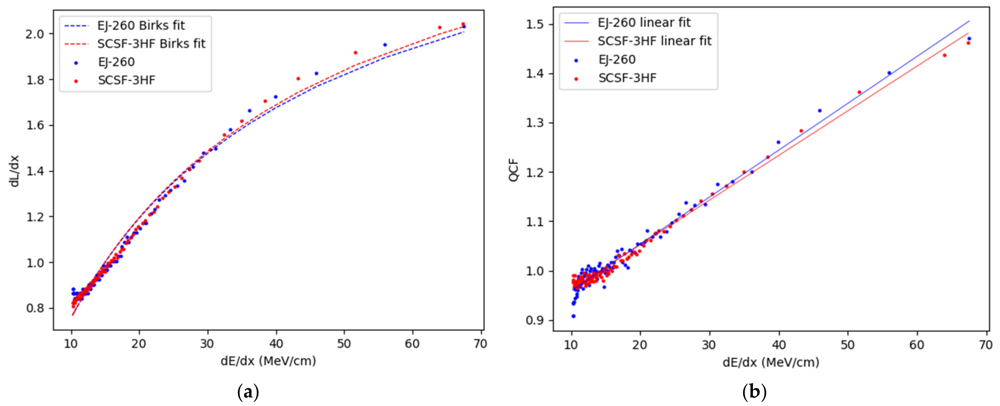
2.7. Quenching Correction Factors

The signal output for both scintillator sensors was plotted against LET and fit to Birks’ equation in its first-order approximation (setting C = 0) as performed by Hoehr et al. [18], and Birks’ constant k B was obtained from the fit. A Stopping and Range of Ions in Matter (also known as the SRIM software package) simulation [44] of the LET in water based on our 74 MeV proton beam was used to create an LET vs. position spline. The QCFs for the two scintillators were obtained in the same manner as by Wang et al. [16]. The positions of the two scintillators and Markus chamber were shifted to align the peaks, then the interpolated RBP depth dose spline measured by the Markus chamber was divided by each scintillator’s interpolated RBP spline to obtain the QCF. A linear fit was applied to the resulting QCF with the intercept set to zero, from which the line of best fit and R2 value were generated.

2.8. Spectrometer Methods

To acquire a wavelength spectrum of the irradiated sensor, the SCSF-3HF scintillator was positioned at the centre of the 23 mm SOBP in the water box, and the EJ-260 was positioned in the Bragg peak in air with the distal end of each sensor coupled to an SM442-URN010-USB spectrometer (Spectral Products Putnam, CT, USA) via SMA-905. The spectrometer was operated with an acquisition time of 4 s and two acquisitions were obtained as background, then the proton beam was run for 50,000 monitor counts at 10 nA for both scintillators. Two backgrounds were obtained after the beam was shuttered, and the backgrounds before and after the spectral acquisition were averaged and subtracted from the total.

3. Results and Discussion

3.1. Proton Dose Response

To determine dose response, the accumulated, background-subtracted scintillator-fibre counts (FC) for each trial were plotted against the administered monitor counts in Figure 3a. A linear fit was applied in Microsoft Excel, and R2 values calculated. The resulting curves were linear with intercepts set to zero and slopes of 14.759 FC/MC (1054 FC/cGy) for EJ-260 and 15.259 FC/MC (1090 FC/cGy) for SCSF-3HF: both have R2 values of 1. The standard deviation is represented with error bars (too small to see for some data points); thus, both sensors satisfy the requirement to be linear for dose response in typical beam currents for proton therapy.

3.2. Proton Dose Rate Response

To determine the dose rate response for the two scintillators, the background-subtracted count rates (FC/s) were plotted against the dose rate as expressed in MC/s for irradiations at set currents of 2, 6, and 10 nA (see Figure 3b). Linear fits were applied with the intercepts set to zero. Resulting R2 values were 0.9997 for EJ-260 and 0.998 for SCSF-3HF.

3.3. Raw Bragg Peak Depth Dose

The RBPs are plotted in Figure 4. The BP heights of the two scintillators are lower than that measured by the Markus chamber. Normalized peak-to-entrance ratios were 2.59 for the EJ-260 scintillator and 2.63 for the SCSF-3HF scintillator, compared to 3.70 for the Markus chamber. Under a theoretically perfect scintillator signal response, the peak-to-entrance ratio is expected to approach that of the Markus chamber, but both sensors present a lower peak height, likely due to quenching in the high-LET area of the BP. The peak width at 80% height was 2.4 mm for EJ-260, 2.3 mm for SCSF-3HF, and 1.5 mm for the Markus chamber; therefore, the requirement of energy independence is not met by these sensors, and corrective measures must be taken in the form of Birks’ quenching correction.

3.4. Spread-Out Bragg Peak Depth Dose

The SOBP obtained using the 23 mm calibration modulator wheel was characterized using the scintillator sensors and a Markus chamber, as shown in Figure 5. After the characteristic initial signal upswing from 0–13 mm depth, neither of the scintillator SOBPs exhibit a flat plateau followed by a sharp distal fall off, as shown by the Markus chamber. Instead, for both scintillators, the signal has a smooth and continuous downward trend. This is qualitatively consistent with signal quenching as observed in the raw Bragg peak measurements. The SOBP beginning position already shows a lower signal intensity than that of the Markus chamber for both sensors; this indicates that signal quenching is potentially present throughout the SOPB measurement, despite the lower effective LET in the beginning region.
The ratio of normalized EJ-260 and SCSF-3HF signal counts to the normalized Markus chamber signal intensity were found at three positions: the initial flat area before the peak, the SOBP centre, and a sampled data point in the area just prior to the final RBP drop-off (see Table 1). It is clear that the scintillator-to-Markus chamber ratios drop consistently as the distal Bragg peak is approached, a finding consistent with the highest effective LET being at the distal fall-off.
Figure 5. SOBP comparison between EJ-260, SCSF-3HF, and Markus chamber dosimeters. The Markus chamber and SCSF-3HF data were shifted to align the peak positions with EJ-260 due to different sizes of the detectors. This shift is not an unexpected consequence of different initial measurement positions of the active area in the water phantom.
Electronics 12 00011 g005

3.5. Quenching Correction

The signal outputs of the RBP measurements were plotted against the simulated LET and normalized to 1 at 15 MeV/cm: both scintillators exhibit very similar quenching curves (see Figure 6a). Birks’ constant k B is calculated to be 0.0367 for EJ-260 and 0.0355 for SCSF-3HF. The QCF was obtained for the two fibres and plotted against LET in Figure 6b for depths of 2 mm to 40 mm. A linear fit was applied, and the equations of best fit found. Q C F E J 260 = 0.864 + 0.0095 L E T and   Q C F S C S F 3 H F = 0.871 + 0.0091 L E T . Using the Python scipy.stats.linregress function, the EJ-260 fit was found to have an R2 value of 0.971, and SCSF-3HF an R2 value of 0.988. These results are comparable to results found by Wang et al. and Hoehr et al. [16,17].
.

3.6. Proton and Neutron Sensitivity Results

Each scintillator’s sensitivity to protons in the SOBP centre—that is, a beam of mostly protons which also contains neutrons as a result of proton interactions with proton beam shaping and monitoring elements and the water in the water box [26]—was compared to the sensitivity to neutrons (only) at TNF. The results are shown in Figure 7. The SCSF-3HF sensor is 3.04 times more sensitive to the TNF neutron beam than the EJ-260, based on the average of three trials for each as shown in Table 2. The SCSF-3HF is only 1.30 times more sensitive than EJ-260 to protons. This difference in sensitivity ratios between the SCSF-3HF and EJ-260 scintillators presents the possibility for proton–neutron discrimination using the two scintillators in a single discriminator detector. This possibility was demonstrated for inorganic sensors in our proposed discriminator detector paper [45], which also takes into account the mixed proton/neutron field used in proton measurements.

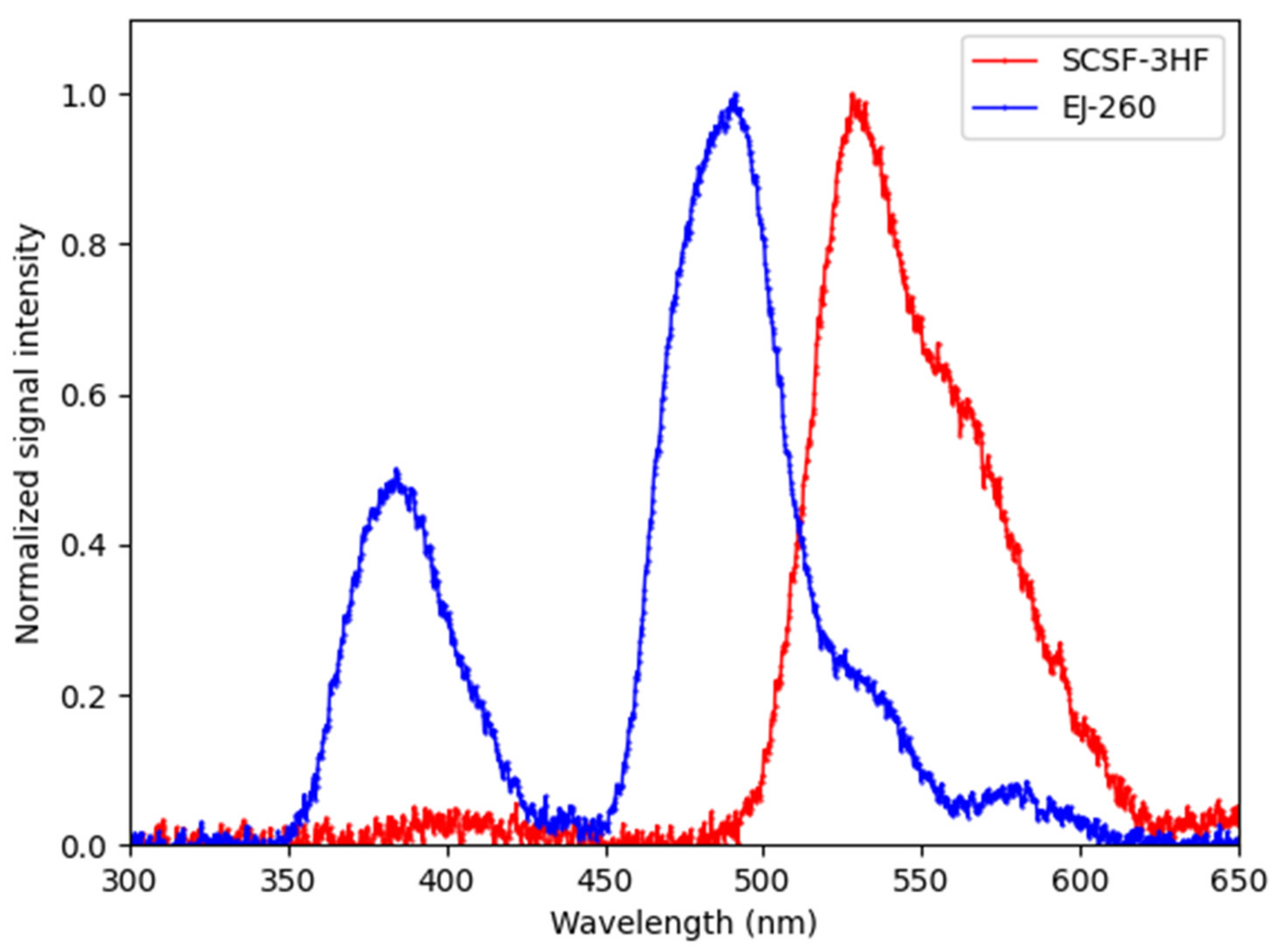
3.7. Scintillator Spectra

The spectrometer data obtained for the two scintillators are plotted in Figure 8. The SCSF-3HF spectrum shows a significant peak centred at 528 nm, and the EJ-260 has two peaks, with the main peak centred at 490 nm. The different peak positions could further enable discrimination between proton and neutron dose: if using a long-pass filter at 525 nm, the SCSF-3HF, with a higher neutron-to-proton sensitivity than EJ-260, would make up the majority of the signal, while the signal under 525 nm would be mainly the EJ-260, with a lower neutron-to-proton sensitivity. This can allow us to ascertain the proton-to-neutron ratio with just one photocounter in a two-step process where the measurement is performed first without the filter and then with the filter inserted.

4. Conclusions

The studies carried out on two different 3 mm organic scintillators, SCSF-3HF and EJ-260, showed that they exhibited linear response to both dose and dose rate, and acceptable sensitivity in both proton (mixed) and neutron radiation. Both sensors were found to quench at high LET, as is also observed in many other organic and inorganic scintillators, but they are also candidates for quenching corrections, as described by Birks. The two sensors performed very similarly under proton irradiation in terms of high LET quenching, Bragg-peak shape, and proton sensitivity. However, the SCSF-3HF sensor was significantly more sensitive to neutrons than the EJ-260, that is, a reduction in the secondary neutron field at the measurement position in the proton beam is expected to decrease the output ratio of SCSF-3HF, as compared to EJ-260. In the ongoing search for quick and reliable particle detection, and in this case, particularly, to discriminate between particles in the neutron-contaminated proton beams used in proton therapy, the sensitivity variation observed here between the two sensors appears very promising. Along with the ability to correct for quenching at high LET, high signal-to-noise ratios, and their small, millimeter size, these sensors are made of organic materials, making them nearly water-equivalent and minimizing proton and neutron beam perturbation. Together, this makes this pair of fibres a viable candidate for a single proton–neutron discriminator sensor.

Author Contributions

Conceptualization, C.H. and C.P.; methodology, C.P., J.N. and C.H.; software, S.U. and J.N.; validation, S.U., C.P. and J.N.; formal analysis, C.B.-C., J.N., S.U., C.P. and C.H.; investigation, C.P., S.U., J.N., C.B.-C., M.T. and C.H.; resources, C.B.-C., M.T., E.P. and C.H.; data curation, J.N., C.P. and S.U.; writing—original draft preparation, C.P., S.U., J.N. and C.H.; writing—review and editing, all; visualization, J.N., S.U. and C.P.; supervision, E.P., C.P., C.B.-C. and C.H.; project administration, E.P. and C.H.; funding acquisition, C.H. All authors have read and agreed to the published version of the manuscript.

Funding

TRIUMF receives funding via a contribution agreement with the National Research Council of Canada (NRC). This research was funded by the National Sciences and Engineering Research Council of Canada (NSERC) via the Discovery grant program (RGPIN-2016-03972).

Acknowledgments

We would like to thank Eljen Technology and Kuraray for providing scintillator materials for testing. We also thank BC Cancer, Vancouver, for fabrication of and modelling assistance for the fibre coupling jig.

Conflicts of Interest

The authors declare no conflict of interest.

References

  1. Gonod, M.; Avila, C.C.; Suarez, M.A.; Crouzilles, J.; Laskri, S.; Vinchant, J.-F.; Aubignac, L.; Grosjean, T. Miniaturized scintillator dosimeter for small field radiation therapy. Phys. Med. Biol. 2021, 66, 115016. [Google Scholar] [CrossRef]
  2. Kam, W.; Ioannou, A.; Martyn, M.; Sullivan, F.; Pospori, A.; Woulfe, P.; Kalli, K.; O’Keeffe, S. Plastic scintillator-based fibre dosimeters for measurement of X-ray pulses in a clinical setting. In Proceedings of the Micro-Structured and Specialty Optical Fibres VII, Strasbourg, France, 3–7 April 2022; pp. 79–86. [Google Scholar]
  3. Debnath, S.B.C.; Tonneau, D.; Fauquet, C.; Tallet, A.; Goncalves, A.; Darreon, J. Dosimetric characterization of a small-scale (Zn, Cd) S: Ag inorganic scintillating detector to be used in radiotherapy. Phys. Med. 2021, 84, 15–23. [Google Scholar] [CrossRef]
  4. Belley, M.D.; Langloss, B.W.; Stanton, I.N.; Meltsner, S.; Craciunescu, O.; Therien, M.J.; Yoshizumi, T.T.; Chino, J.P. A High Precision in-vivo Dosimeter for Real Time Quality Assurance in HDR Brachytherapy, Based off a Nano-crystalline Scintillator Fiber-Optic Radiation Sensor. Brachytherapy 2015, 14, S27–S28. [Google Scholar] [CrossRef]
  5. Jørgensen, E.B.; Johansen, J.G.; Overgaard, J.; Piché-Meunier, D.; Tho, D.; Rosales, H.M.; Tanderup, K.; Beaulieu, L.; Kertzscher, G.; Beddar, S. A high-Z inorganic scintillator—Based detector for time-resolved in vivo dosimetry during brachytherapy. Med. Phys. 2021, 48, 7382–7398. [Google Scholar] [CrossRef]
  6. Cometti, S.; Gierej, A.; Giaz, A.; Lomazzi, S.; Baghdasaryan, T.; Van Erps, J.; Berghmans, F.; Santoro, R.; Caccia, M.; O’Keeffe, S. Characterization of scintillating materials in use for brachytherapy fiber based dosimeters. Nucl. Instrum. Methods Phys. Res. Sect. A Accel. Spectrometers Detect. Assoc. Equip. 2022, 1042, 167083. [Google Scholar] [CrossRef]
  7. Woulfe, P.; Sullivan, F.J.; Byrne, L.; Doyle, A.; Kam, W.; Martyn, M.; O’Keeffe, S. Optical fibre based real-time measurements during an LDR prostate brachytherapy implant simulation: Using a 3D printed anthropomorphic phantom. Sci. Rep. 2021, 11, 11160. [Google Scholar] [CrossRef]
  8. Ding, L.; Wu, Q.; Wang, Q.; Li, Y.; Perks, R.M.; Zhao, L. Advances on inorganic scintillator-based optic fiber dosimeters. EJNMMI Phys. 2020, 7, 1–23. [Google Scholar] [CrossRef]
  9. Jean, E.; Therriault-Proulx, F.; Beaulieu, L. Comparative optic and dosimetric characterization of the HYPERSCINT scintillation dosimetry research platform for multipoint applications. Phys. Med. Biol. 2021, 66, 085009. [Google Scholar] [CrossRef]
  10. Cerenkov, P. Visible glow under exposure of gamma radiation. In Proceedings of the Doklady Akademii Nauk SSSR; Psycho-Mathematical Institute V.A. Steklova, Academy of Science: Saint Petersburg, Russia, 1934; Volume 2, p. 451. [Google Scholar]
  11. Lee, B.; Jang, K.W.; Yoo, W.J.; Shin, S.H.; Moon, J.; Han, K.-T.; Jeon, D. Measurements of cerenkov lights using optical fibers. IEEE Trans. Nucl. Sci. 2013, 60, 932–936. [Google Scholar]
  12. Chou, C. The nature of the saturation effect of fluorescent scintillators. Phys. Rev. 1952, 87, 904. [Google Scholar] [CrossRef]
  13. Pöschl, T.; Greenwald, D.; Losekamm, M.J.; Paul, S. Measurement of ionization quenching in plastic scintillators. Nucl. Instrum. Methods Phys. Res. Sect. A Accel. Spectrometers Detect. Assoc. Equip. 2021, 988, 164865. [Google Scholar] [CrossRef]
  14. Birks, J.B. Scintillations from organic crystals: Specific fluorescence and relative response to different radiations. Proc. Phys. Society. Sect. A 1951, 64, 874. [Google Scholar] [CrossRef]
  15. Birks, J. Theory and Practice of Scintillation Counting. International Series of Monographs in Electronics and Instrumentation; Elsevier: Amsterdam, The Netherlands, 1964; Volume 27, p. 187. [Google Scholar]
  16. Wang, L.; Perles, L.; Archambault, L.; Sahoo, N.; Mirkovic, D.; Beddar, S. Determination of the quenching correction factors for plastic scintillation detectors in therapeutic high-energy proton beams. Phys. Med. Biol. 2012, 57, 7767. [Google Scholar]
  17. Hoehr, C.; Lindsay, C.; Beaudry, J.; Penner, C.; Strgar, V.; Lee, R.; Duzenli, C. Characterization of the exradin W1 plastic scintillation detector for small field applications in proton therapy. Phys. Med. Biol. 2018, 63, 095016. [Google Scholar]
  18. Alsanea, F.; Darne, C.; Robertson, D.; Beddar, S. Ionization quenching correction for a 3D scintillator detector exposed to scanning proton beams. Phys. Med. Biol. 2020, 65, 075005. [Google Scholar] [CrossRef]
  19. Christensen, J.B.; Almhagen, E.; Stolarczyk, L.; Vestergaard, A.; Bassler, N.; Andersen, C.E. Ionization quenching in scintillators used for dosimetry of mixed particle fields. Phys. Med. Biol. 2019, 64, 095018. [Google Scholar] [CrossRef] [Green Version]
  20. FitzGerald, T.J.; Ding, L.; Riberdy, C.; Bailey, J.; Anderegg, M.; Elaimy, A.; Shen, J.; O’Connor, K.; Bradford, C.; Kuo, I.-L. The Future of Proton Therapy. In Proton Therapy - Current Status and Future Directions; IntechOpen: London, UK, 2021. [Google Scholar] [CrossRef]
  21. Englbrecht, F.S.; Trinkl, S.; Mares, V.; Rühm, W.; Wielunski, M.; Wilkens, J.J.; Hillbrand, M.; Parodi, K. A comprehensive Monte Carlo study of out-of-field secondary neutron spectra in a scanned-beam proton therapy gantry room. Z. Med. Phys. 2021, 31, 215–228. [Google Scholar]
  22. Leite, A.; Ronga, M.; Giorgi, M.; Ristic, Y.; Perrot, Y.; Trompier, F.; Prezado, Y.; Crehange, G.; De Marzi, L. Secondary neutron dose contribution from pencil beam scanning, scattered and spatially fractionated proton therapy. Phys. Med. Biol. 2021, 66, 225010. [Google Scholar] [CrossRef]
  23. Sørensen, B.S.; Pawelke, J.; Bauer, J.; Burnet, N.G.; Dasu, A.; Høyer, M.; Karger, C.P.; Krause, M.; Schwarz, M.; Underwood, T.S. Does the uncertainty in relative biological effectiveness affect patient treatment in proton therapy? Radiother. Oncol. 2021, 163, 177–184. [Google Scholar]
  24. Penner, C.; Woulfe, P.; Stoeber, B.; Duzenli, C.; O’Keeffe, S.; Hoehr, C. Novel optical fibre-based sensors for neutron and proton beams. In Proceedings of the 2019 IEEE SENSORS, Montreal, PQ, Canada, 27–30 October 2019; pp. 1–4. [Google Scholar]
  25. Hupman, M.A. Development of a Novel Radiation Dosimeter: The Stemless Plastic Scintillation Detector. IEEE Sens. 2021. [Google Scholar] [CrossRef]
  26. Goulet, M.; Rilling, M.; Gingras, L.; Beddar, S.; Beaulieu, L.; Archambault, L. Novel, full 3D scintillation dosimetry using a static plenoptic camera. Med. Phys. 2014, 41, 082101. [Google Scholar] [CrossRef]
  27. Darne, C.D.; Robertson, D.G.; Alsanea, F.; Collins-Fekete, C.-A.; Beddar, S. A novel proton-integrating radiography system design using a monolithic scintillator detector: Experimental studies. Nucl. Instrum. Methods Phys. Res. Sect. A Accel. Spectrometers Detect. Assoc. Equip. 2022, 1027, 166077. [Google Scholar] [CrossRef]
  28. Kam, W.; Martyn, M.; Olusoji, O.; Woulfe, P.; O’Keeffe, S. Plastic Scintillation Fibre Dosimetry for Monitoring of External Beam Radiation Therapy. In Proceedings of the Optical Sensors, Vancouver, BC, Canad, 11–15 July 2022; p. STu4C. 2. [Google Scholar]
  29. Archambault, L.; Arsenault, J.; Gingras, L.; Sam Beddar, A.; Roy, R.; Beaulieu, L. Plastic scintillation dosimetry: Optimal selection of scintillating fibers and scintillators. Med. Phys. 2005, 32, 2271–2278. [Google Scholar] [CrossRef]
  30. Yoshida, T.; Sora, T. A prototype avalanche photodiode array for scintillating-fiber tracking detectors. Nucl. Instrum. Methods Phys. Res. Sect. A Accel. Spectrometers Detect. Assoc. Equip. 2004, 534, 397–402. [Google Scholar] [CrossRef]
  31. Kanouta, E.; Johansen, J.G.; Kertzscher, G.; Sitarz, M.K.; Sørensen, B.S.; Poulsen, P.R. Time structure of pencil beam scanning proton FLASH beams measured with scintillator detectors and compared with log files. Med. Phys. 2022, 49, 1932–1943. [Google Scholar] [CrossRef]
  32. Hoehr, C.; Hanna, M.; Zeisler, S.; Penner, C.; Stokely, M.; Dehnel, M. Ce- and B-Doped Silica Fibers for Monitoring Low-Energy Proton Beams on a Medical Cyclotron. Appl. Sci. 2020, 10, 4488. [Google Scholar] [CrossRef]
  33. Penner, C.; Hoehr, C.; Morana, A.; Vidalot, J.; Hocini, E.; Penner, C.; Trinczek, M.; Butiv, O.; Boukenter, A.; Ouerdane, Y. Nitrogen-doped single-mode inorganic optical fibres for radiotherapy dosimetry: Scientific Session 4A: Radiation Dosimetry–08. Med. Phys. 2019, 46, 5390. [Google Scholar]
  34. Safai, S.; Lin, S.; Pedroni, E. Development of an inorganic scintillating mixture for proton beam verification dosimetry. Phys. Med. Biol. 2004, 49, 4637. [Google Scholar] [CrossRef]
  35. Archambault, L.; Polf, J.C.; Beaulieu, L.; Beddar, S. Characterizing the response of miniature scintillation detectors when irradiated with proton beams. Phys. Med. Biol. 2008, 53, 1865. [Google Scholar] [CrossRef] [Green Version]
  36. Kim, S.H.; Lee, J.W.; Jung, W.S.; Ahn, J.K.; Jung, M.H.; Kim, Y.J. Three-dimensional measurement of a proton beam profile at KOMAC with a scintillating fiber detector. Nucl. Instrum. Methods Phys. Res. Sect. A Accel. Spectrometers Detect. Assoc. Equip. 2022, 1034, 166832. [Google Scholar] [CrossRef]
  37. Ozkan Loch, C.; Eichenberger, M.A.; Togno, M.; Zinsli, S.P.; Egloff, M.; Papa, A.; Ischebeck, R.; Lomax, A.J.; Peier, P.; Safai, S. Characterization of a low-cost plastic fiber array detector for proton beam dosimetry. Sensors 2020, 20, 5727. [Google Scholar] [CrossRef]
  38. Beyer, K.A.; Di Fulvio, A.; Stolarczyk, L.; Parol, W.; Mojżeszek, N.; Kopéc, R.; Clarke, S.D.; Pozzi, S.A. Organic Scintillator for Real-Time Neutron Dosimetry. Radiat. Prot. Dosim. 2018, 180, 355–359. [Google Scholar] [CrossRef]
  39. Yagi, T.; Misawa, T.; Pyeon, C.H.; Shiroya, S. A small high sensitivity neutron detector using a wavelength shifting fiber. Appl. Radiat. Isot. 2011, 69, 176–179. [Google Scholar] [CrossRef]
  40. Miller, C.A.; Di Fulvio, A.; Clarke, S.D.; Pozzi, S.A. Dual-Particle Dosemeter Based on Organic Scintillator. Radiat. Prot. Dosim. 2020, 191, 319–327. [Google Scholar] [CrossRef]
  41. Blackmore, E.; Evans, B.; Mouat, M. Operation of the TRIUMF proton therapy facility. In Proceedings of the 1997 Particle Accelerator Conference (Cat. No. 97CH36167), Vancouver, BC, Canada, 12–16 May 1997; pp. 3831–3833. [Google Scholar]
  42. Penner, C.; Hoehr, C.; Lindsay, C.; Duzenli, C.; O’Keeffe, S. Timing resolution for an optical fibre-based detector in a 74 MeV proton therapy beam. J. Phys. Conf. Ser. 2018, 1067, 062001. [Google Scholar] [CrossRef]
  43. Blackmore, E.W.; Dodd, P.E.; Shaneyfelt, M.R. Improved capabilities for proton and neutron irradiations at TRIUMF. In Proceedings of the 2003 IEEE Radiation Effects Data Workshop, Monterey, CA, USA, 25 July 2003; pp. 149–155. [Google Scholar]
  44. Ziegler, J.F.; Ziegler, M.D.; Biersack, J.P. SRIM—The stopping and range of ions in matter. Nucl. Instrum. Methods Phys. Res. Sect. B Beam Interact. Mater. At. 2010, 268, 1818–1823. [Google Scholar] [CrossRef]
  45. Niedermeier, J.; Penner, C.; Usherovich, S.; Bélanger-Champagne, C.; Paulßen, E.; Hoehr, C. Optical fibres as dosimeter detector for mixed proton/neutron fields—A biological dosimeter. In Proceedings of the 2021 CAP Virtual Congress, Virtual, 7–10 June 2021. [Google Scholar]
Figure 1. Assembly of an SCSF-3HF fibre-scintillator detector while in the coupling jig.
Electronics 12 00011 g001
Figure 2. PTRC extracted 74 MeV beamline showing structures traversed by the beam before ending in the water box. The modulator wheel is absent for RBP measurements and present for the SOBP.
Electronics 12 00011 g002
Figure 3. Dose and dose rate responses: (a) dose response comparison between the EJ-260 and SCSF-3HF fibres at three dose levels: 10,000 MC (1.4 Gy), 100,000 MC (14 Gy), and 500,000 MC (70 Gy). Error bars, some too small to be seen against the data point, indicate standard deviation in the mean of three averaged irradiations at each dose; (b) dose rate response comparison between EJ-260 and SCSF-3HF at three different beam currents: 2, 6, and 10 nA for an exposure of 50,000 MC (7 Gy) each.
Electronics 12 00011 g003
Figure 4. RBP comparison between EJ-260, SCSF-3HF, and Markus chamber dosimeters.
Electronics 12 00011 g004
Figure 6. (a) Scintillator sensor output vs. LET with Birks’ first-order fit. (b) QCF vs. LET with linear fits. Curves are normalized to 1 at 15   MeV / cm .
Electronics 12 00011 g006
Figure 7. Proton (purple) and neutron (orange) sensitivity comparison between the EJ-260 and SCSF-3HF sensors. Error bars indicate standard deviation of the three trials for each experiment.
Electronics 12 00011 g007
Figure 8. Spectra for the two scintillators normalized with their maxima at 1.
Electronics 12 00011 g008
Table 1. Normalized detector output at three positions along the SOBP.
PositionMarkus ChamberEJ-260SCSF-3HF
SOBP beginning (12.7 mm)1.2051.1621.170
SOBP centre (24.2 mm)1.1891.0971.104
SOBP drop-off (34.2 mm)1.1190.8910.895
Table 2. MPPC signal with standard deviation comparing EJ-260 and SCSF-3HF in protons and neutrons. The highest signal (SCSF-3HF) was set to 1, and EJ-260 was scaled accordingly. Uncertainty is the standard deviation in the three trials for each fibre.
ScintillatorSensitivity to Protons (FC/cGy)Sensitivity to Neutrons (FC/cGy)
EJ-260 0.770 ± 0.002 0.329 ± 0.006
SCSF-3HF 1.000 ± 0.008 1.00 ± 0.06
Disclaimer/Publisher’s Note: The statements, opinions and data contained in all publications are solely those of the individual author(s) and contributor(s) and not of MDPI and/or the editor(s). MDPI and/or the editor(s) disclaim responsibility for any injury to people or property resulting from any ideas, methods, instructions or products referred to in the content.

