
High-Isolation MIMO Antenna for 5G Millimeter-Wave Communication Systems


Abstract
:1. Introduction
2. Antenna Design and Characterization
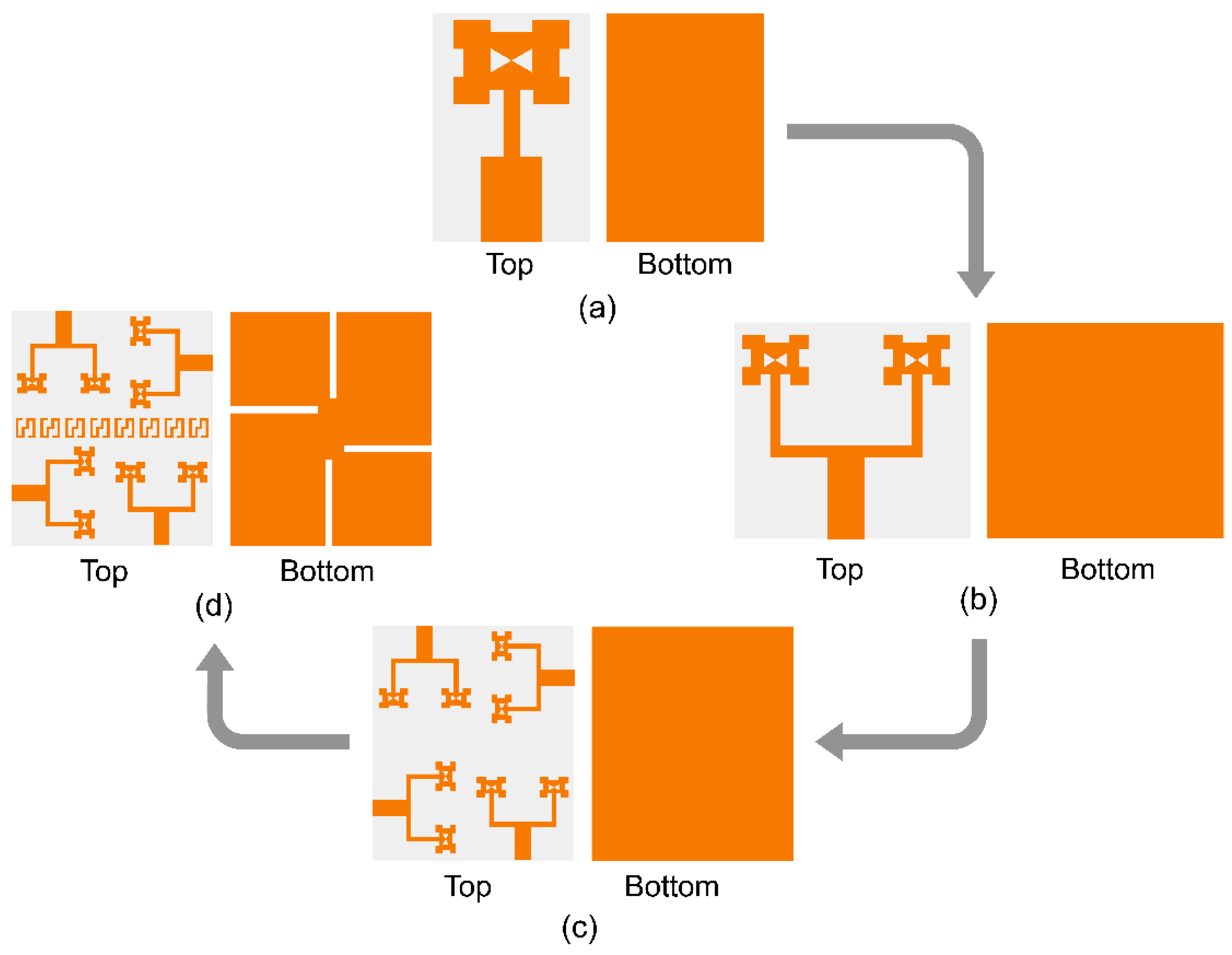
2.1. Single Antenna
Parametric Analysis
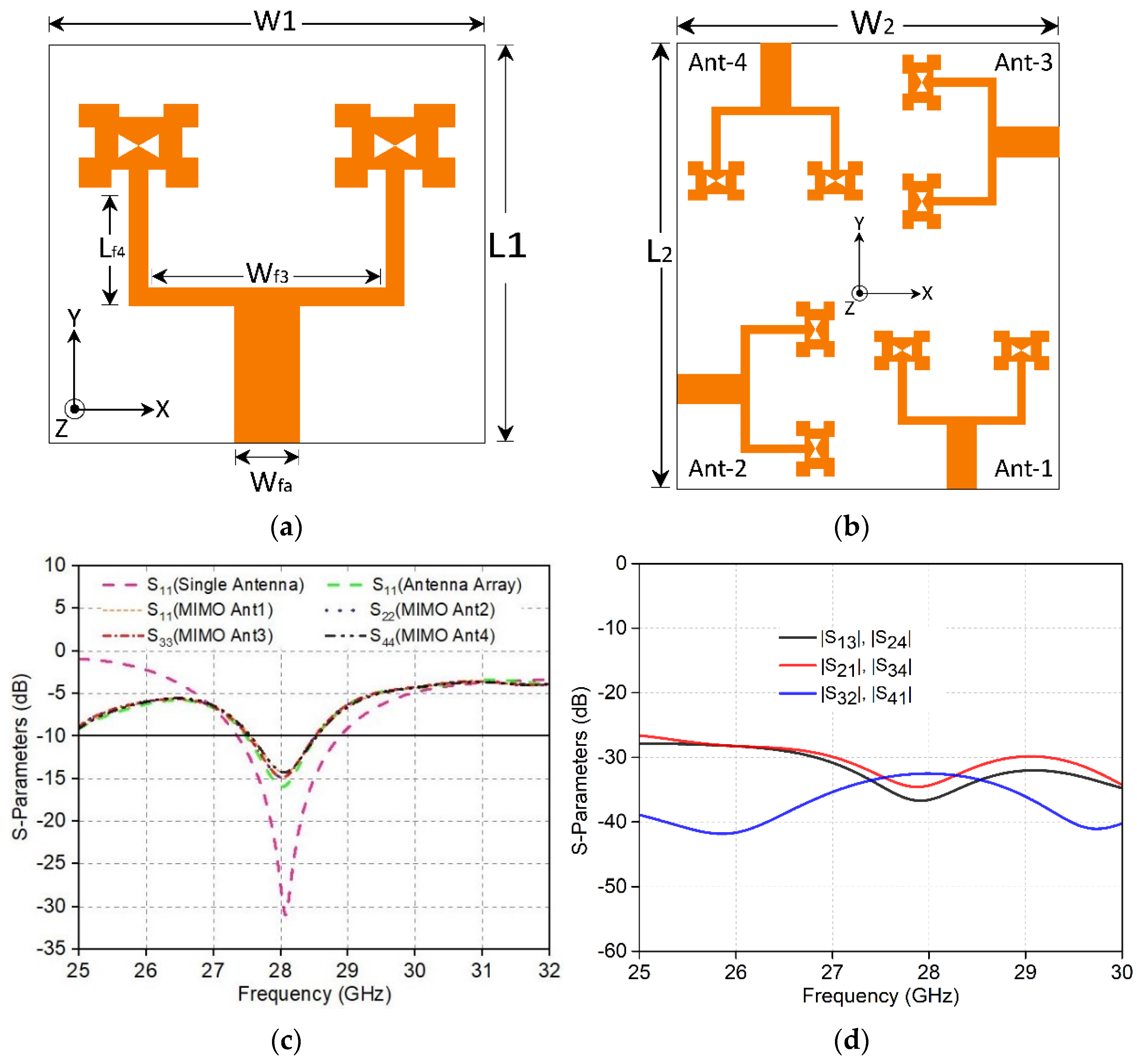
2.2. Antenna Array
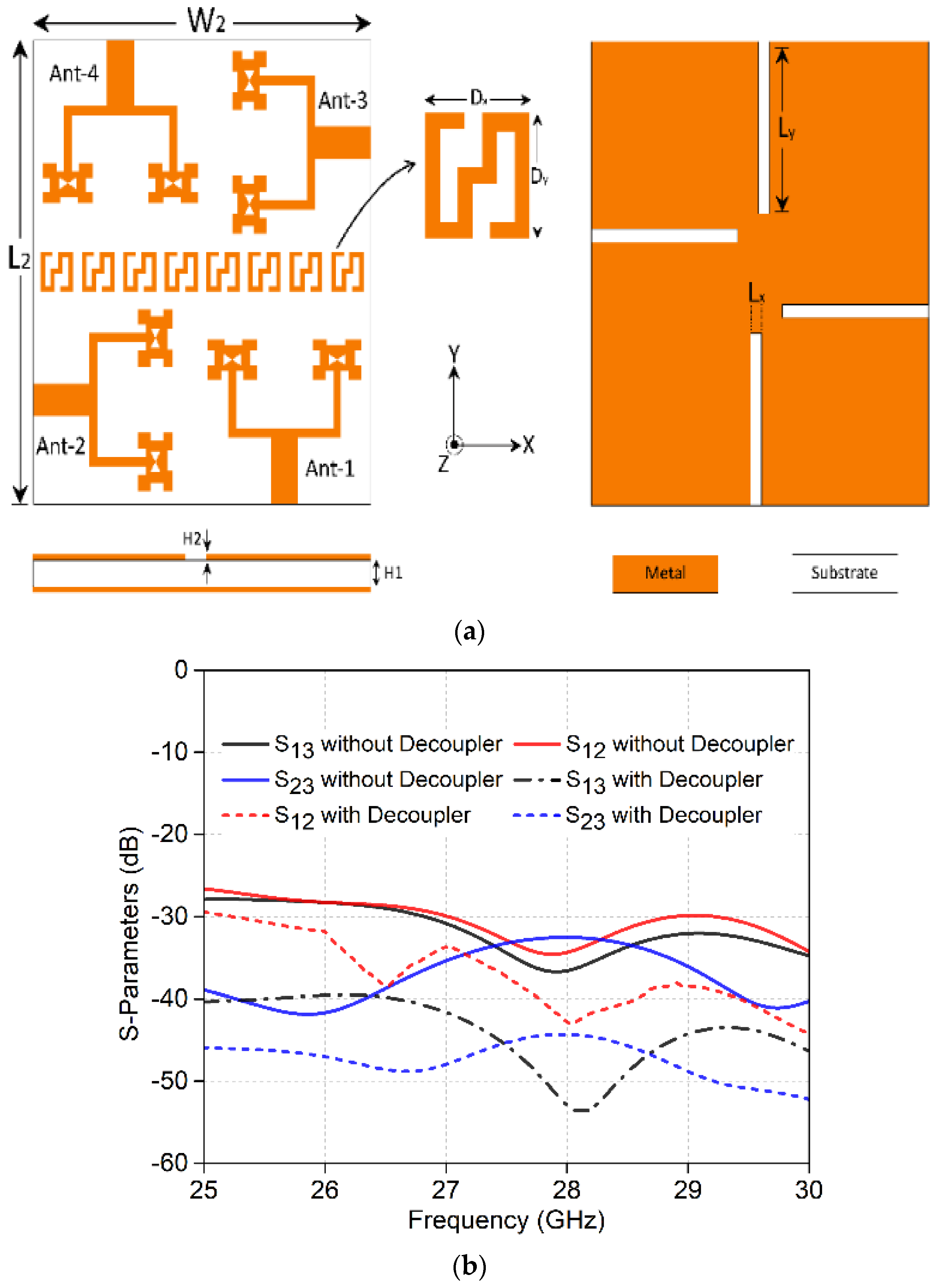
2.3. MIMO Structure
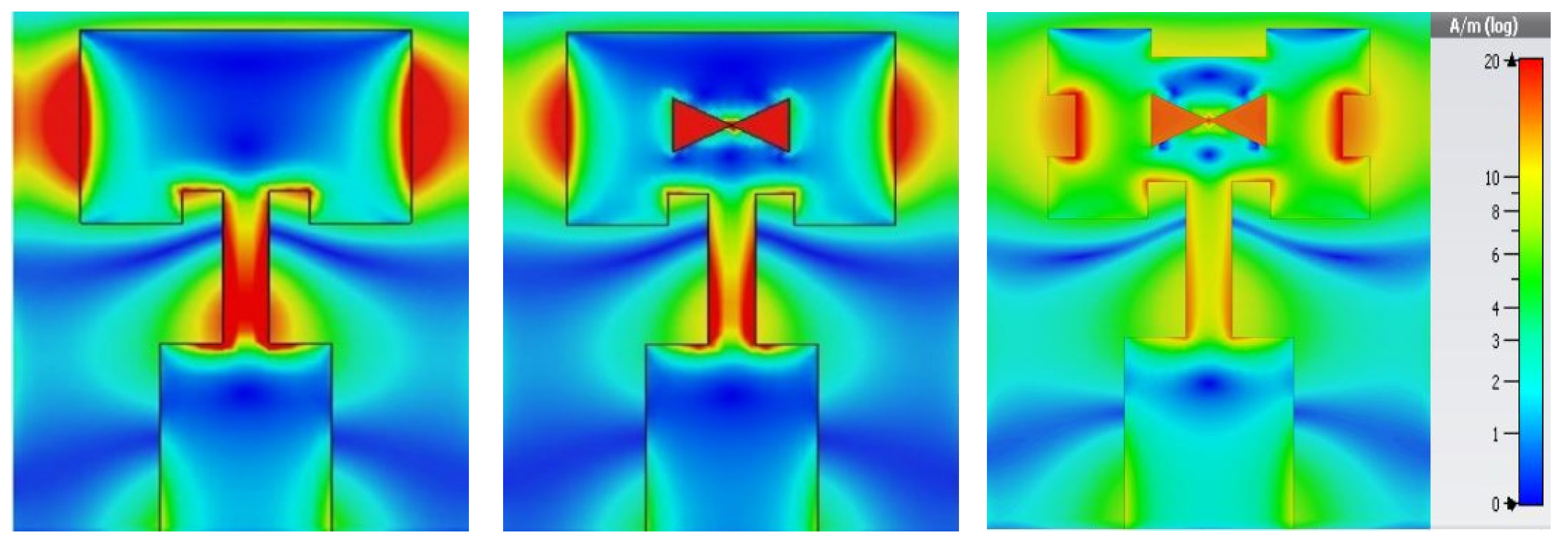
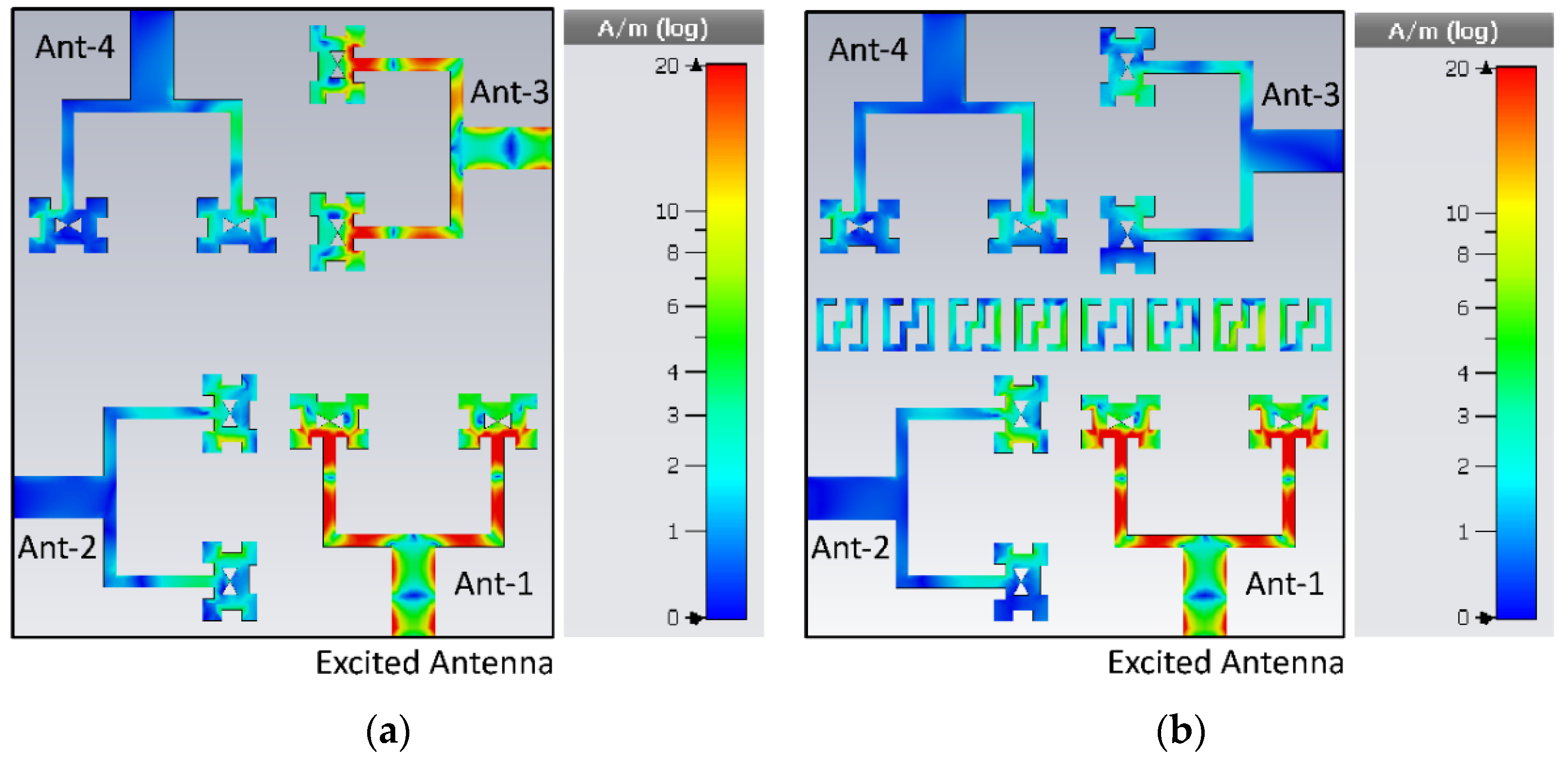
2.4. Performance Analysis of DGS and Decoupler
3. Results and Discussion
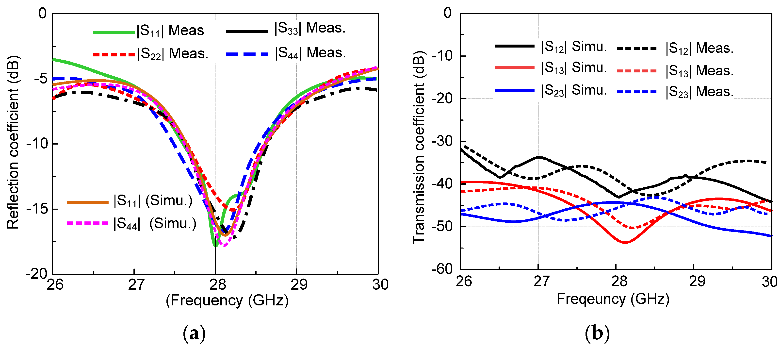
3.1. Reflection and Transmission Coefficients
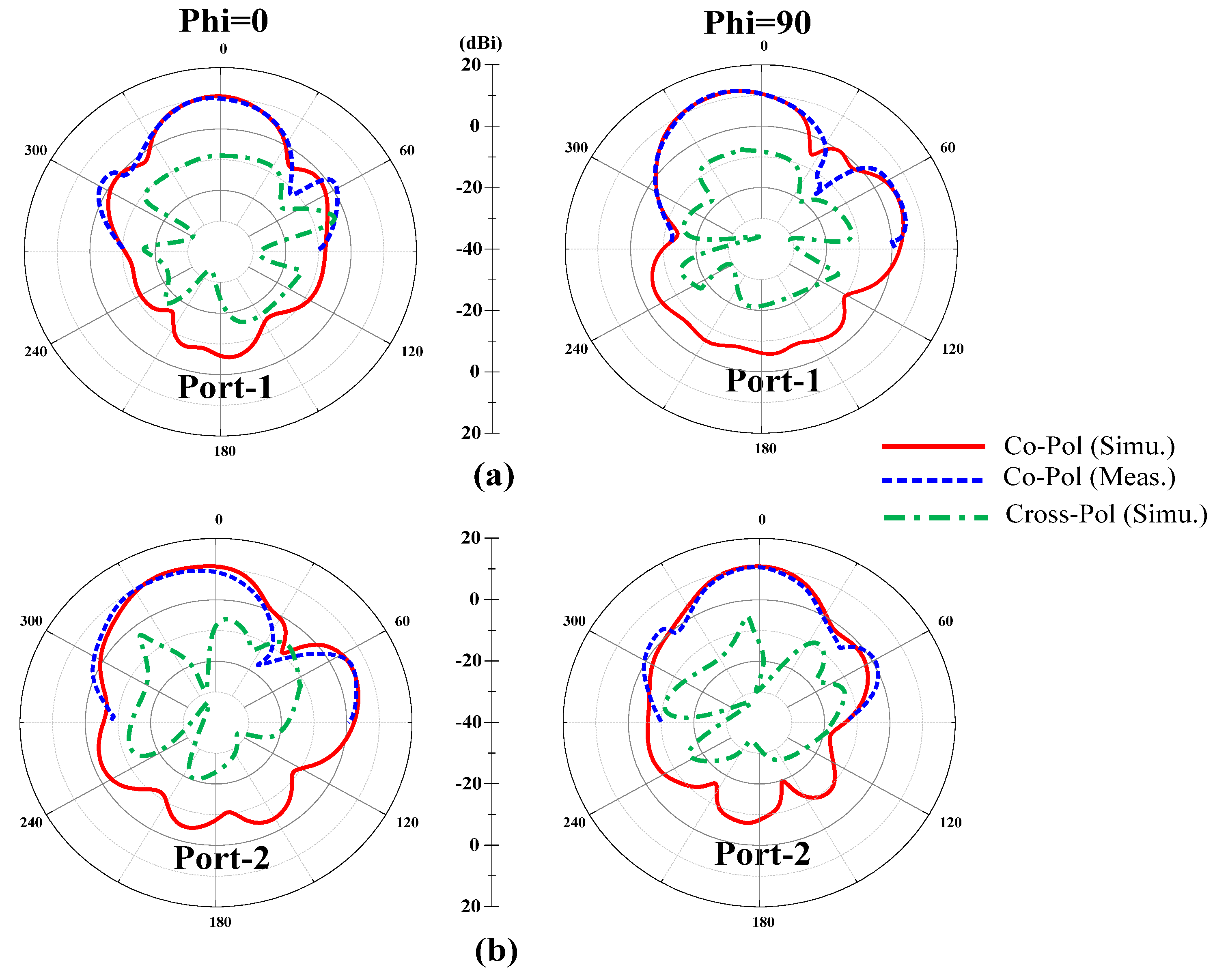
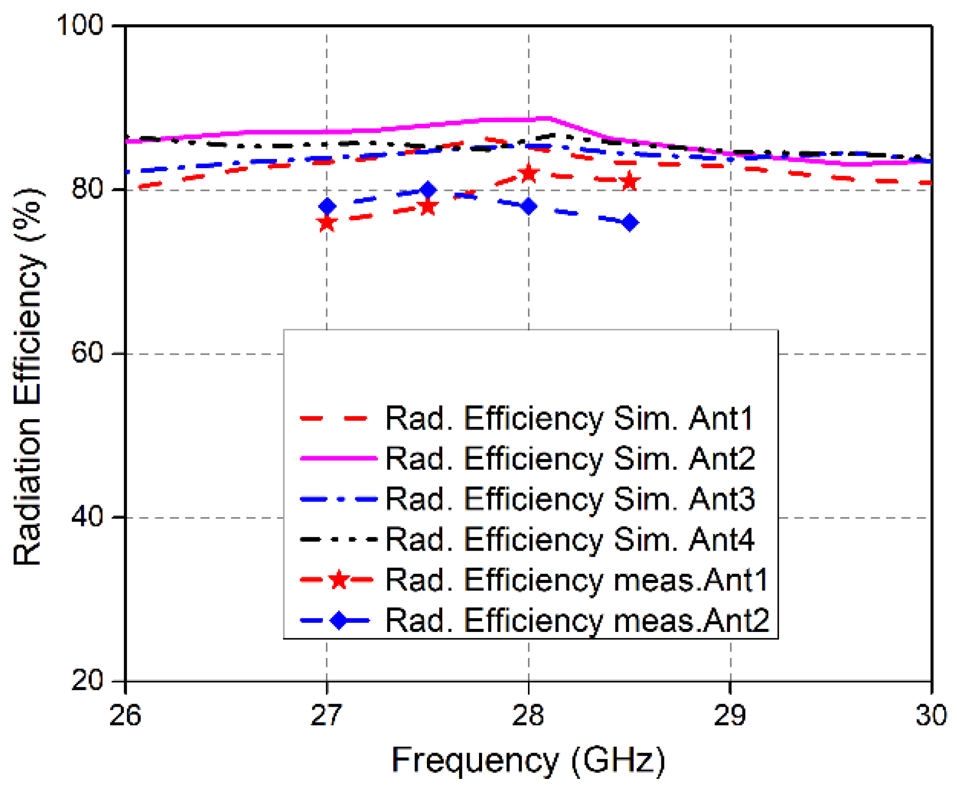
3.2. Far-Field Results
3.3. Diversity Performance Analysis
4. Comparison with State-of-the-Art Works
5. Conclusions
Author Contributions
Funding
Conflicts of Interest
References
- Vannithamby, R.; Talwar, S. (Eds.) Towards 5G: Applications, Requirements and Candidate Technologies; John Wiley & Sons: Hoboken, NJ, USA, 2017; ISBN 978-1-118-97991-4. Available online: https://www.wiley.com/en-us/Towards+5G%3A+Applications%2C+Requirements+and+Candidate+Technologies-p-9781118979914 (accessed on 30 September 2021).
- da Silva, M.M.; Guerreiro, J. On the 5G and Beyond. Appl. Sci. 2020, 10, 7091. [Google Scholar] [CrossRef]
- Hilt, A. Availability and Fade Margin Calculations for 5G Microwave and Millimeter-Wave Anyhaul Links. Appl. Sci. 2019, 9, 5240. [Google Scholar] [CrossRef] [Green Version]
- Varga, P.; Peto, J.; Franko, A.; Balla, D.; Haja, D.; Janky, F.; Soos, G.; Ficzere, D.; Maliosz, M.; Toka, L. 5G support for Indus-trial IoT Applications—Challenges, Solutions, and Research gaps. Sensors 2020, 20, 828. [Google Scholar] [CrossRef] [PubMed] [Green Version]
- Qualcomm Technologies Inc. Spectrum for 4G and 5G. 2017. Available online: https://www.qualcomm.com/news/media-center (accessed on 30 September 2021).
- European 5G Observatory. National 5G Spectrum Assignment. Available online: https://5gobservatory.eu/ (accessed on 10 May 2020).
- Shayea, I.; Rahman, T.A.; Azmi, M.H.; Islam, R. Real Measurement Study for Rain Rate and Rain Attenuation Conducted over 26 GHz Microwave 5G Link System in Malaysia. IEEE Access 2018, 6, 19044–19064. [Google Scholar] [CrossRef]
- Hussain, N.; Jeong, M.J.; Park, J.; Kim, N. A broadband circularly polarized Fabry-Perot resonant antenna using a sin-gle-layered PRS for 5G MIMO applications. IEEE Access 2019, 7, 42897–42907. [Google Scholar] [CrossRef]
- Nguyen-Trong, N.; Tran, H.H.; Nguyen, T.K.; Abbosh, A.M. A Compact Wideband Circular Polarized Fabry-Perot Antenna Using Resonance Structure of Thin Dielectric Slabs. IEEE Access 2018, 6, 56333–56339. [Google Scholar] [CrossRef]
- Lin, Q.W.; Wong, H.; Zhang, X.Y.; Lai, H.W. Printed Meandering Probe-Fed Circularly Polarized Patch Antenna with Wide Bandwidth. IEEE Antennas Wirel. Propag. Lett. 2014, 13, 654–657. [Google Scholar] [CrossRef]
- Wong, H.; Lin, Q.W.; Lai, H.W.; Zhang, X.Y. Substrate integrated meandering probe-fed patch antennas for wideband wire-less devices. IEEE Trans. Compon. Packag. Manuf. Technol. 2015, 5, 381–388. [Google Scholar] [CrossRef]
- Hussain, N.; Nguyen, T.K.; Han, H.; Park, I. Minimum Lens Size Supporting the Leaky-Wave Nature of Slit Dipole Antenna at Terahertz Frequency. Int. J. Antennas Propag. 2016, 2016, 1–8. [Google Scholar] [CrossRef] [Green Version]
- Song, Z.; Zheng, H.; Wang, M.; Li, E.; Li, Y. Design of One-Eighth Spherical Dielectric Resonator Antenna for 5G Applications. IEEE Access 2020, 8, 9480–9487. [Google Scholar] [CrossRef]
- Dzagbletey, P.A.; Jung, Y.-B. Stacked Microstrip Linear Array for Millimeter-Wave 5G Baseband Communication. IEEE Antennas Wirel. Propag. Lett. 2018, 17, 780–783. [Google Scholar] [CrossRef]
- Khalily, M.; Tafazolli, R.; Xiao, P.; Kishk, A.A. Broadband mm-Wave Microstrip Array Antenna with Improved Radiation Characteristics for Different 5G Applications. IEEE Trans. Antennas Propag. 2018, 66, 4641–4647. [Google Scholar] [CrossRef]
- Naqvi, S.I.; Naqvi, A.H.; Arshad, F.; Riaz, M.A.; Azam, M.A.; Khan, M.S.; Amin, Y.; Loo, J.; Tenhunen, H. An Integrated Antenna System for 4G and Millimeter-Wave 5G Future Handheld Devices. IEEE Access 2019, 7, 116555–116566. [Google Scholar] [CrossRef]
- Araújo, D.C.; Maksymyuk, T.; De Almeida, A.L.F.; Maciel, T.F.; Mota, J.C.; Jo, M. Massive MIMO: Survey and future re-search topics. IET Commun. 2016, 10, 1938–1946. [Google Scholar] [CrossRef] [Green Version]
- Sethi, W.T.; Ashraf, M.A.; Ragheb, A.; Alasaad, A.; Alshebeili, S.A. Demonstration of Millimeter Wave 5G Setup Employing High-Gain Vivaldi Array. Int. J. Antennas Propag. 2018, 2018, 1–12. [Google Scholar] [CrossRef] [Green Version]
- Jeong, M.J.; Hussain, N.; Park, J.W.; Park, S.G.; Rhee, S.Y.; Kim, N. Millimeter-wave microstrip patch antenna using vertical-ly coupled split ring metaplate for gain enhancement. Microw. Opt. Technol. Lett. 2019, 61, 2360–2365. [Google Scholar] [CrossRef]
- Saad, A.A.R.; Mohamed, H.A. Printed millimeter-wave MIMO-based slot antenna arrays for 5G networks. AEU Int. J. Electron. Commun. 2019, 99, 59–69. [Google Scholar] [CrossRef]
- Wang, F.; Duan, Z.; Wang, X.; Zhou, Q.; Gong, Y. High Isolation Millimeter-Wave Wideband MIMO Antenna for 5G Com-munication. Int. J. Antennas Propag. 2019, 2019, 4283010. [Google Scholar] [CrossRef]
- Ali, W.; Das, S.; Medkour, H.; Lakrit, S. Planar dual-band 27/39 GHz millimeter-wave MIMO antenna for 5G applications. Microsyst. Technol. 2020, 27, 283–292. [Google Scholar] [CrossRef]
- Al-Bawri, S.S.; Islam, M.T.; Shabbir, T.; Muhammad, G.; Islam, S.; Wong, H.Y. Hexagonal Shaped Near Zero Index (NZI) Metamaterial Based MIMO Antenna for Millimeter-Wave Application. IEEE Access 2020, 8, 181003–181013. [Google Scholar] [CrossRef]
- Sehrai, D.A.; Abdullah, M.; Altaf, A.; Kiani, S.H.; Muhammad, F.; Tufail, M.; Irfan, M.; Glowacz, A.; Rahman, S. A Novel High Gain Wideband MIMO Antenna for 5G Millimeter Wave Applications. Electronics 2020, 9, 1031. [Google Scholar] [CrossRef]
- Kamal, M.; Yang, S.; Ren, X.-C.; Altaf, A.; Kiani, S.; Anjum, M.; Iqbal, A.; Asif, M.; Saeed, S. Infinity Shell Shaped MIMO Antenna Array for mm-Wave 5G Applications. Electronics 2021, 10, 165. [Google Scholar] [CrossRef]
- Khalid, M.; Naqvi, S.I.; Hussain, N.; Rahman, M.; Fawad; Mirjavadi, S.S.; Khan, M.J.; Amin, Y. 4-Port MIMO Antenna with Defected Ground Structure for 5G Millimeter Wave Applications. Electronics 2020, 9, 71. [Google Scholar] [CrossRef] [Green Version]
- Balanis, C.A. Antenna Theory: Analysis and Design, 3rd ed.; Wiley Interscience: Hoboken, NJ, USA, 2005; ISBN 047166782X. [Google Scholar]
- Blanch, S.; Romeu, J.; Corbella, I. Exact representation of antenna system diversity performance from input parameter description. Electron. Lett. 2003, 39, 705. [Google Scholar] [CrossRef] [Green Version]
- Sharawi, M.S. Printed Multi-Band MIMO Antenna Systems and Their Performance Metrics [Wireless Corner]. IEEE Antennas Propag. Mag. 2013, 55, 218–232. [Google Scholar] [CrossRef]
- Sharawi, M.S. Printed MIMO Antenna Engineering; Artech House: Norwood, MA, USA, 2014; ISBN 9781608076819. [Google Scholar]


| Parameter | Value | Parameter | Value | Parameter | Value |
|---|---|---|---|---|---|
| W | 6 | L | 8.5 | G1 | 0.5 |
| Wf1 | 2.2 | Lf1 | 3.1 | G2 | 1 |
| Wf2 | 4.2 | Lf2 | 2.4 | Lf3 | 3.06 |
| W1 | 15.5 | L1 | 15.15 | Wf3 | 8.7 |
| Lf4 | 5.45 | Wf4 | 5.45 | H1 | 0.787 |
| W3 | 30 | L3 | 35 | Dx | 2.91 |
| Dy | 3 | Lx | 13 | Ly | 1 |
| Freq (GHz) | Ant # | Peak Gain (dBi) | |
|---|---|---|---|
| Simulated | Measured | ||
| 27.5 | Ant1 | 10.73 | 10.25 |
| Ant2 | 10.51 | 10.01 | |
| 28 | Ant1 | 12.24 | 12.02 |
| Ant2 | 11.71 | 11.46 | |
| 28.5 | Ant1 | 11.35 | 11.12 |
| Ant2 | 11.04 | 10.88 | |
| Ref | Freq (GHz) | Bandwidth (GHz) | Substrate | Board Size (mm2) | Number of Ports | Gain (dBi) | Isolation (dB) | ECC, DG (dB) | CCL |
|---|---|---|---|---|---|---|---|---|---|
| [20] | 28/38 | 22.5–29, 33.5–50 | Rogers RO 4003C (εr = 3.38) | 53 × 3.17 | 2 ports | 11.5 | 20 | 0.12, >9.4 | NP * |
| [21] | 28 | 24–29, 30.5–36 | Rogers RO 4003C (εr = 3.38) | 126 × 126 | 81 ports | 7.8 | 20 | <0.005, 9.99 | NP * |
| [22] | 27/39 | 25–28.2, 36–41 | Rogers RO 4003C (εr = 3.38) | 26 × 11 | 2 ports | 5, 5.7 | >30 | 0.0001, >9.99 | NP * |
| [23] | 28 | 24–29.9 | Rogers RT 5880 (εr = 2.2) | 52 × 23 | 2 ports | 12.4 | >24 | <0.0013, >9.9 | <0.42 |
| [24] | 28/38 | 23–40 | Rogers RT 5880 (εr = 2.2) | 80 × 80 | 4 ports | 12 | >20 | <0.0014 | NP * |
| [25] | 28 | 27–28.5 | Rogers RT 5880 (εr = 2.2) | 30 × 30 | 4 ports | 6.1 | >29 | <0.16, NP | NP * |
| [26] | 28 | 25.5–29.6 | Rogers RO 4350B (εr = 3.48) | 30 × 35 | 4 ports | 8.3 | 17 | <0.01, >9.96 | <0.4 |
| This Work | 28 | 27.5–28.5 | Rogers RT 5880 (εr = 2.2) | 30 × 35 | 4 ports | 12 | >40 | <0.0003, >9.9 | <0.4 |
Publisher’s Note: MDPI stays neutral with regard to jurisdictional claims in published maps and institutional affiliations. |
© 2022 by the authors. Licensee MDPI, Basel, Switzerland. This article is an open access article distributed under the terms and conditions of the Creative Commons Attribution (CC BY) license (https://creativecommons.org/licenses/by/4.0/).
Share and Cite
Bilal, M.; Naqvi, S.I.; Hussain, N.; Amin, Y.; Kim, N. High-Isolation MIMO Antenna for 5G Millimeter-Wave Communication Systems. Electronics 2022, 11, 962. https://doi.org/10.3390/electronics11060962
Bilal M, Naqvi SI, Hussain N, Amin Y, Kim N. High-Isolation MIMO Antenna for 5G Millimeter-Wave Communication Systems. Electronics. 2022; 11(6):962. https://doi.org/10.3390/electronics11060962
Chicago/Turabian StyleBilal, Muhammad, Syeda Iffat Naqvi, Niamat Hussain, Yasar Amin, and Nam Kim. 2022. "High-Isolation MIMO Antenna for 5G Millimeter-Wave Communication Systems" Electronics 11, no. 6: 962. https://doi.org/10.3390/electronics11060962