Article

Effect of Phase Noise on the Optical Millimeter-Wave Signal in the DWDM-RoF System

by
Rawa Muayad Mahmood
1,
Syamsuri Yaakob
1,*,
Faisul Arif Ahmad
1,
Siti Barirah Ahmad Anas
1,
Muhammad Zamzuri Abdul Kadir
2 and
Mohd Rashidi Che Beson
3
1
WIPNET, Department of Computer and Communication Systems Engineering, Faculty of Engineering, Universiti Putra Malaysia (UPM), Serdang 43400, Selangor, Malaysia
2
Kulliyyah of Science, International Islamic, University Malaysia, Jalan Sultan Ahmad Shah, Bandar Indera Mahkota, Kuantan 25200, Pahang, Malaysia
3
Advanced Communication Engineering, Centre of Excellence (ACE-CoE), School of Computer and Communication Engineering, Universiti Malaysia Perlis, Kangar 01000, Perlis, Malaysia
*
Author to whom correspondence should be addressed.
Electronics 2022, 11(3), 489; https://doi.org/10.3390/electronics11030489
Submission received: 27 November 2021 / Revised: 24 January 2022 / Accepted: 29 January 2022 / Published: 8 February 2022
(This article belongs to the Special Issue Advances in Millimeter-Wave Cellular Networks)

Abstract

:
In this study, we examined the effect of phase noise on the optical millimeter-wave (mm-wave) signal in a dense wavelength division multiplexing radio-over-fiber (DWDM-RoF) system. A single modulator was used to generate the optical mm-wave signal in the DWDM-RoF system. This paper addresses the impact of phase noise, which results from phase imbalance, on the optical mm-wave signal. To lower the effect of phase noise on the optical mm-wave signal, the phase imbalance should be controlled. The phase imbalance can be controlled and decreased by adjusting the phase at the phase shift (PS). The system performance was analyzed using various parameters such as bit error rate (BER), signal-to-noise ratio (SNR), optical signal to noise ratio (OSNR), and error vector magnitude (EVM). From the results, we found the phase imbalance affected the optical mm-wave signal due to the imbalanced splitting of the signal intensity at the MZM. The phase imbalance impacts the phase noise, which impacts the optical mm-wave signal. The phase noise could be decreased by controlling the phase imbalance at the phase of 5π/12. The best results at the phase of 5π/12 were collected for phase noise at 0.02 degrees.

Graphical Abstract

1. Introduction

During the past few years, the communication industry has experienced rapid expansion in the number of worldwide users and an increase in the speed of transmission data [1]. Therefore, it will be necessary for future access networks to merge both photonic technology and radio-over-fiber (RoF) technology to provide high-flexibility and sufficient systems to the end-user. Dense wavelength division multiplexing (DWDM) and RoF technologies have been proven to support cost-effective and high-capacity access for the transmission data networks. The technology of DWDM is based on RoF, combining the benefits of optical fiber and millimeter-wave wireless systems.
The millimeter-wave (mm-wave) band has great potential in RoF technology due to its wide transmission bandwidth and unlicensed frequency band. In addition, the 5G traffic requirements will necessitate improvements to the design of radio access networks (RANs), which depend on unused ranges of frequencies such as the mm-wave range. Different applications, such as complementing terrestrial RANs with unmanned arial vehicles (UAVs), can be cost-effective and flexible strategies with the 5G radio access networks, as reported in [2]. Furthermore, the mm-wave technology is capable of meeting the increasing demands of wireless applications [3,4,5,6]. However, in the electrical domain, the generation of mm waves with high frequency remains a challenge due to the current restrictions on frequency responses of electronic devices and equipment. Therefore, several researchers are focusing on mm-wave generation using photonic techniques [7,8].
Several techniques have been reported to improve the capacity of RoF communication systems [9,10,11]. The performance of multiple modulation formats, such as dual-polarization quadrature phase-shift keying (DP-QPSK), dual-polarization 16-ary quadrature amplitude modulation (DP-16QAM), DP-64QAM, and DP-256QAM, was studied in C-band systems with different transmission distances. It was found that the capacity for enhancing achievable data rates strongly depends on signal modulation formats as well as the transmission distances [11].
Additionally, the DWDM technique enhanced the capability of traffic data by using multiple transmission channels in the photonic communication networks. The DWDM is a cost-effective technique that avoids the need for additional fiber for transmission. Furthermore, the advantages of DWDM networks make them suitable for long-haul transmission data [12,13,14,15]. However, some equipment hinders the implementation of cost-effective DWDM networks rather than the RoF systems. Some studies utilized a large number of modulators in the system, such as [16,17], in which many Mach Zehnder Modulators (MZMs) are used to generate the optical mm-wave. Using many modulators in the system increases the cost and complexity of the system.
Furthermore, the MZM performance is limited by the uncontrolled phase, which creates a phase imbalance in the mm-wave signals [18]. Therefore, using a large number of MZMs increases the phase imbalance and creates a significant insertion loss in the system [18,19,20]. In addition, the phase imbalance causes phase noise in the mm-wave signal [20]. Therefore, the use of a large number of MZMs and uncontrolled phases cause the mm-wave signal to face significant phase noise. Alternatively, the use of a single modulator in the transmission data systems reduces the phase imbalance in the system and insertion losses as well as the cost and complexity at the remote antenna unit (RAU), especially in cases where a large number of RAUs is deployed. The optical generation of mm waves using a single modulator results in instability and low phase noise in the system [21].
Methods have been presented for the photonic generation of the mm-wave signal [22,23,24,25,26,27]. These studies optically generated the mm wave. However, they did not examine the effects of phase imbalance on the system or the effects of the resulting phase noise. Therefore, there are more parameters and more efficient techniques to be investigated to ensure an excellent system for the future. The DWDM-RoF technique is worth exploring because it generates the optical mm-wave signal using just a single modulator. Therefore, we used a DWDM-RoF architecture using a single MZM to control the phase imbalance, which causes phase noise in mm-wave signals. The DWDM-RoF architecture uses a phase shift component before the MZM to adjust the phase imbalance. The main objectives of our study were to present the DWDM-RoF architecture, generate the 60 GHz mm wave, simulate the DWDM-RoF architecture using a single MZM scheme, and demonstrate the effects of phase noise on the generated optical mm-wave signal in the DWDM-RoF system.

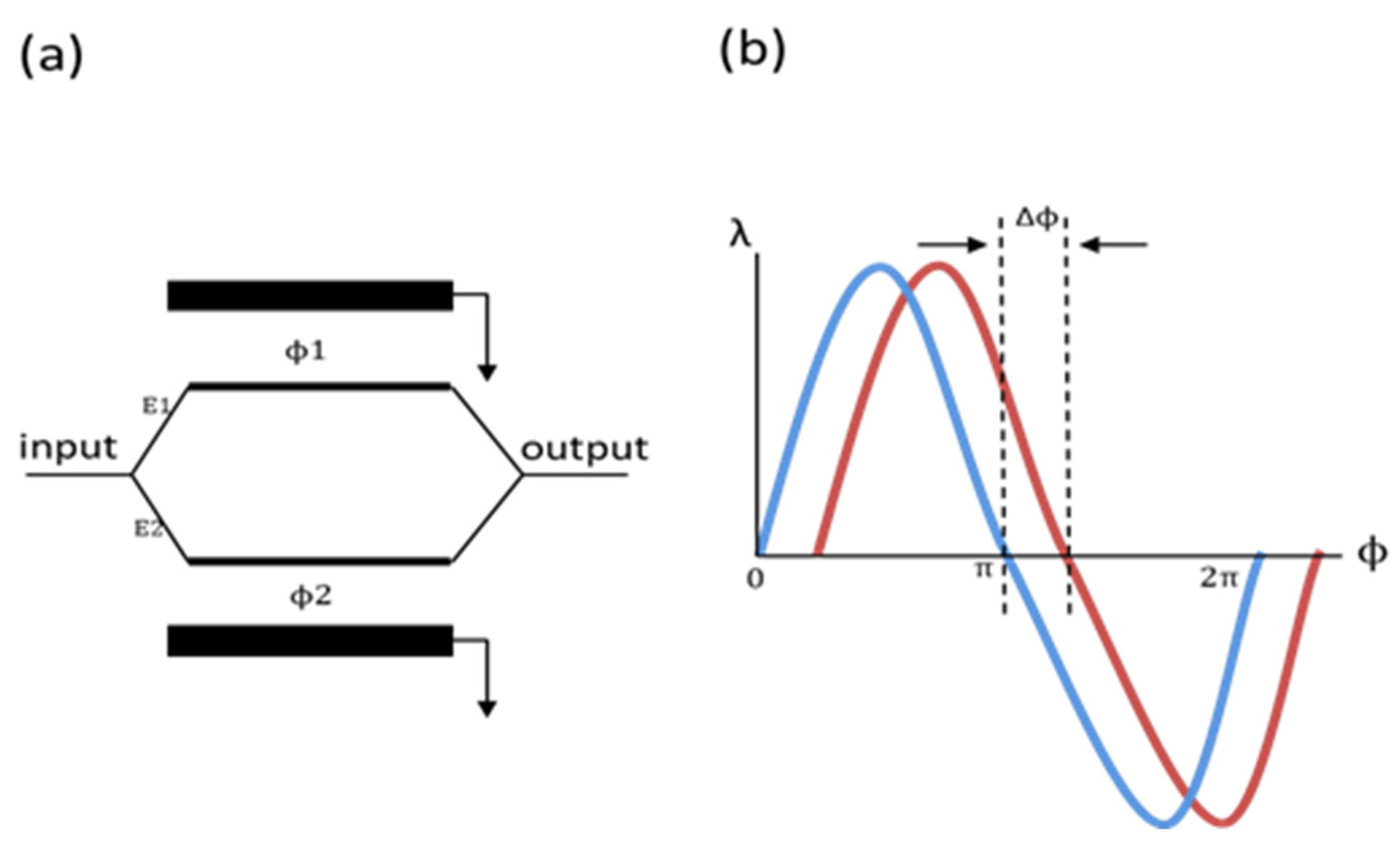
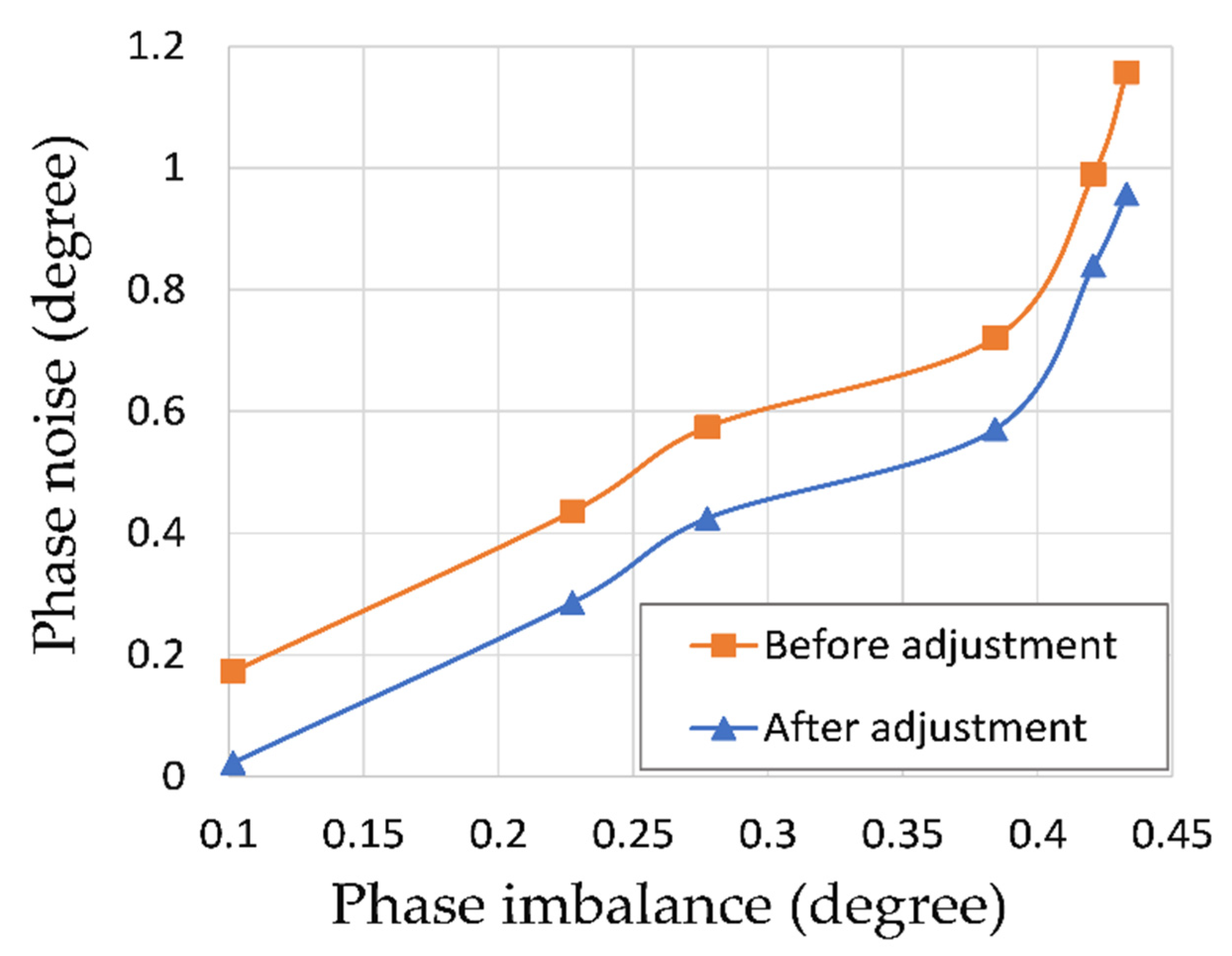
2. Phase Noise and Phase Imbalance Effects
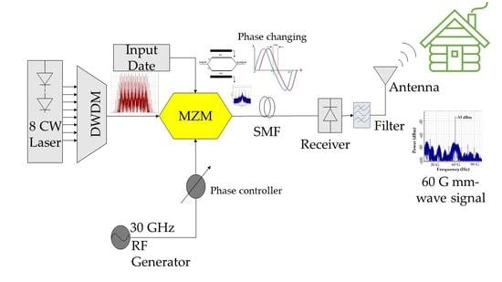
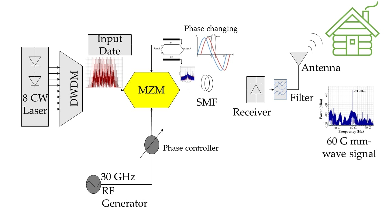
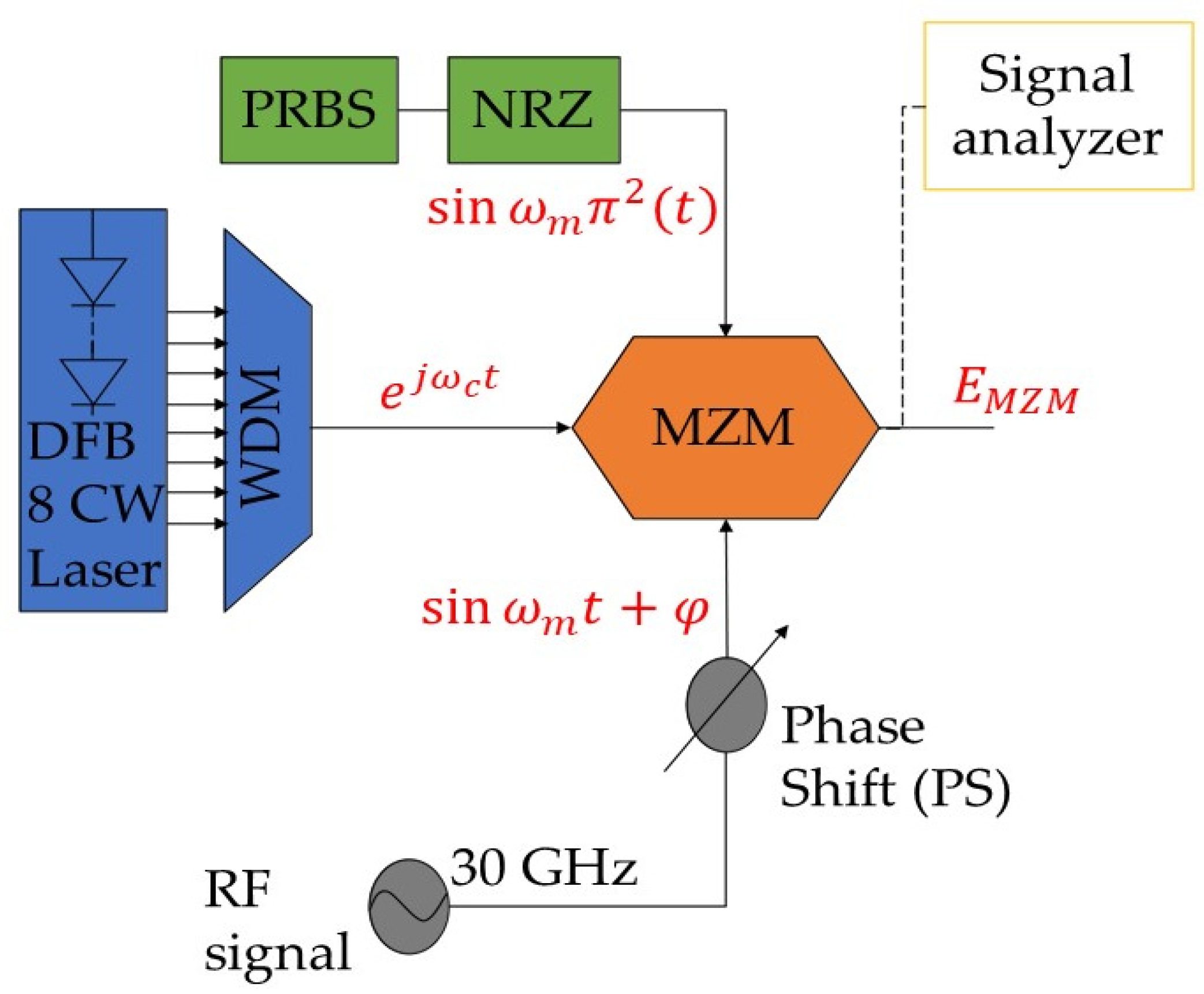
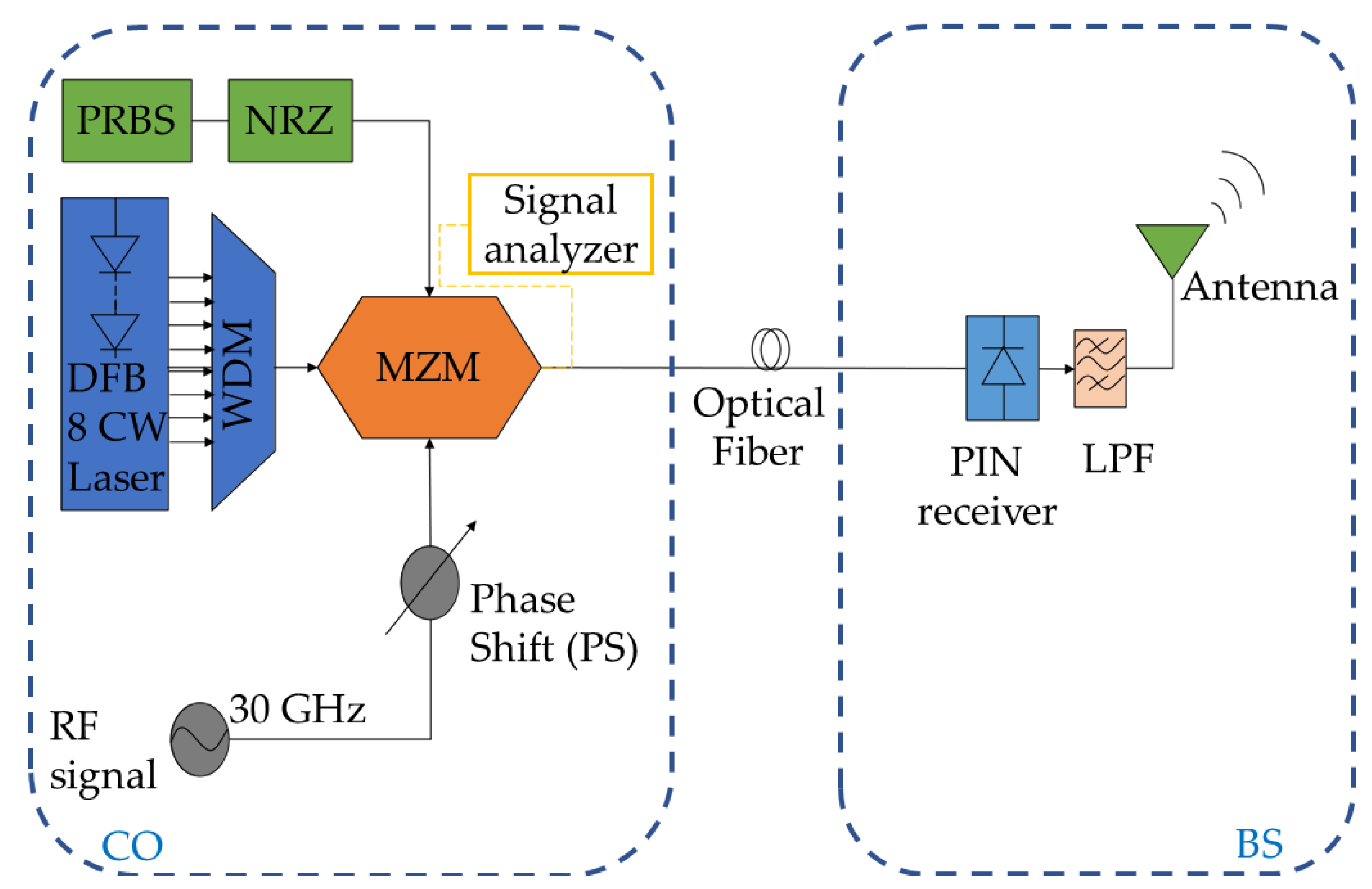
The MZM scheme is still affected by the uncontrol phase in the optical part, which creates an amplitude error in the electrical and wireless signal. Using many MZMs in the system increases the phase imbalance, so by using a single modulator, the phase imbalance effects are limited and controlled. The phase imbalance parameter influences the performance of the optical mm wave, as discussed in our prior work [18]. This is due to the difference in length ∆L between the two branches of the MZM, which results in different beam speeds inside the MZM. These different speeds create a difference between phase ϕ1 and ϕ2 as shown in Figure 1. The phase imbalance can be represented by:
Δ φ = 2 π n Δ L / λ
where n is the refractive index, and λ is the light wave wavelength.
In our study, the phase imbalance was controlled by adjusting the phase at the phase shift. The proposed schematic diagram of the MZM for the DWDM-RoF system was driven by three input sources, as shown in Figure 2. The three input sources were the continuous wave (CW) laser, data consisting of a nonreturn-to-zero (NRZ) generated from a pseudorandom binary sequence (PRBS), and the radio-frequency (RF) signal. Therefore, the output signal EMZM of the MZM was a combination of the three. The following equations expressed the three sources of MZM.
The first source is the pseudorandom binary sequence (PRBS) data. It can be represented by:
T 1   ( t ) = sin ω m π 2 ( t )
where T 1   ( t ) is the electric field of the transmitted data represented by a sine wave of the signal and ωm is the angular frequency (ωm = 2πfm). The second source was the continuous wave (CW) laser. It can be represented by:
T 2   ( t ) = e j ω c t
where T 2   ( t )   is the optical field of the optical carrier, j is the Bessel function of the first kind, and ωc is the light-wave angular frequency (ωc = 2πc/λ) in scalar form (scalar form is used based on the assumption that the light is linearly polarized, and it is aligned with the corresponding polarization state axis of the modulator) [21]. The third source was the radio frequency (RF) signal. It can be represented by:
T 3   ( t ) = sin ω m t + φ
where T 3   ( t ) is the electrical field of the RF signal and φ is the initial phase of electrical drive signal. This phase could be adjusted to control the phase imbalance that occurred at the MZM. According to Equations (2)–(4), the output signal EMZM of the MZM can be expressed by:
E MZM =   α   sin ω m π 2 ( t ) + e j ω c t + sin ω m t + φ
where α is the insertion losses of the modulator, and α is significantly affecting the signal power, as reported [17,18,19].
The phase shift (PS) was used as a controller after the RF signal to control the phase imbalance that occurred at the MZM. The PS can adjust the phase imbalance that affects the mm-wave signal. The phase imbalance was initially calculated at the output of the MZM, and then the phase was adjusted at the PS to decrease the phase imbalance. Theoretically, the phase imbalance affects the insertion losses and the amplitude of the mm-wave signal, as proved in this equation [18]:
| A | = 1 + 2   γ 2 2 γ + 2 γ ( 1 γ ) cos φ  
where A is the amplitude of the signal and γ is the splitting ratio of the MZM scheme. In addition, phase imbalance causes a high phase noise in the mm-wave signal [20]. Low phase noise is the key requirement in modern mm-wave and microwave communication systems to ensure the adequate recovery of the transmitted signals. Thus, low phase noise is essential to enable an efficient system. In general, phase noise can be defined as the frequency-domain representation of random fluctuations in the phase of a waveform. In a simulation system, the phase noise can be calculated using the signal analyzer in the frequency domain. In addition, other parameters such as signal-to-noise ratio (SNR) and error vector magnitude (EVM) have been used to estimate the phase noise [20,28,29,30], while another study used optical signal to noise ratio (OSNR) to describe the noise in the signal [31]. Hence, the effect of phase noise on the optical mm wave can be calculated by identifying the equations of the EVM and SNR values, as expressed in the following equations [20,30]:
EVM 2 ( φ ) = 1 SNR + 2 2 cos ( φ )
SNR ( dB ) = 10 log ( δ 2 )
where φ is the phase imbalance and δ is the phase noise of the mm-wave signal and both affect the EVM. From Equations (7) and (8), the EVM can be expressed by:
EVM 2 ( φ ) = 1 10   log ( δ ^ 2   ) + 2 2 cos ( φ )
Furthermore, the equations of SNR, EVM and OSNR can be expressed by [29,32]:
SNR = ( 1 EVM   ) 2
EVM = ( 1 SNR   )
and
OSNR = 10.7 log ( BER ) 1.45
According to the theoretical expressions, the phase imbalance affects the insertion losses of the mm-wave signal and the amplitude of the signal, as shown in Equations (5) and (6). Equation (7) proves that phase imbalance affects the EVM, where phase imbalance is an important parameter to estimate phase noise. In addition, Equations (8) and (9) show that the phase noise is influenced by the SNR and the phase imbalance of the mm-wave signal. In conclusion, the theoretical expressions shown prove that phase imbalance results in phase noise. The phase noise of the mm-wave signal can be analyzed using SNR and EVM parameters to enhance the results of phase noise from the signal analyzer in the simulated system. The following section discusses the system setup and the implementation of the mm wave in the DWDM-RoF system.

3. Simulation Setup

The DWDM-RoF architecture was simulated using Optisystem software version 18 (Ottawa, ON, Canada). In the simulation, the optical mm-wave generation was set up using a single MZM with three input sources, as explained in the prior section.
At the central office (CO), an array of CW lasers starting at 1550 nm and spaced by 0.8 nm with a power of 10 dBm was used. The CW lasers were connected to wavelength division multiplexing (WDM) to multiplex the wavelengths together before being modulated in the MZM, as shown in Figure 3.
The WDM multiplexer represented the DWDM technique in the architecture. The DWDM technique is flexible, allowing narrowing of the spacing of channels to increase the capacity of the transmitted signal as well the number of channels for the same purpose [33]. In this work, eight channels were used with a channel spacing of 0.8 nm. To generate the 60 GHz mm-wave, the RF signal generator was set to 30 GHz and followed by a PS to control the phase imbalance.
The lasers, RF signal generator, PS, and a binary signal of 2.5 Gb/s in PRBS and NRZ format were connected to a single MZM modulator. The MZM was then connected to an optical fiber before being connected to a positive intrinsic negative (PIN) receiver and lowpass filter (LPF) in the base station (BS).
The eight transmitted channels were received at eight PIN receivers in the BS, each receiver for a specific wavelength. The optical fiber ranged from 0 km to 40 km with a dispersion of 16.75 ps/nm/km and attenuation of 0.2 dB/km. The PIN responsivity was set to 0.7 A/W, and the signal was filtered using the LPF of 0.75 cutoff frequency. Finally, the signal was sent to the antenna. An attenuator of 5 dB was used to represent the antenna in the BS. The signal analyzer was used at the output of the MZM to monitor the phase imbalance and phase noise of the mm-wave signal. Table 1 shows the parameters settings used in this work.

4. Results and Discussion

In the DWDM-RoF system, the eight wavelengths were modulated using a single MZM scheme. Figure 4a shows the individual wavelength at 1550 nm and Figure 4b shows the eight wavelengths modulated together and spaced by 0.8 nm. The mm-wave signal was generated using a single MZM scheme in the DWDM-RoF system. The peak power of the generated 60 GHz mm-wave was –33 dBm, as shown in Figure 5.
In the long-haul coherent optical fiber communication systems, the phase noise affected the electronic dispersion compensation (EDC) module where the equalization-enhanced phase noise (EEPN) occurred due to the interplay between laser phase noise and EDC module. It significantly degraded the performance of the uncompensated long-haul coherent optical fiber communication systems. For further discussion, the EEPN was reported in [34,35,36].
The phase noise of the mm-wave signal in the DWDM-RoF system was monitored through the signal analyzer in the frequency domain. A high phase noise resulting from the phase imbalance of the mm-wave signal at the MZM was observed. To lower the phase noise, the phase imbalance should be controlled. In our study, the phase imbalance could be decreased using the PS.
In the architecture, the single MZM reduced the insertion losses by decreasing the phase imbalance from one side. From the other side, the phase imbalance was best controlled using a single MZM in the system to avoid multiphase imbalance from multiple MZMs. Therefore, we used a single MZM to control the phase imbalance of the optical mm-wave signal. In the system, the phase imbalance was calculated at the output of the MZM and controlled by adjusting the phases at the PS. The controlling process used phases from 0° to 75°, which is equivalent to 0 to 5π/12 radian. Figure 6 shows the phase imbalance vs. the applied phases at the PS. The phase imbalance was controlled and decreased from 0.43° to 0.1°.
To quantify the performance of the mm-wave signal, a constellation diagram was used. In general, a signal sent by an ideal transmitter should result in a constellation diagram with all constellation points precisely at the ideal locations. However, high phase noise and phase imbalance may cause deviation of the constellation points from the ideal locations. The total distance between the points’ locations and the ideal locations represents a corresponding measure of phase noise or error phase in the signal. Figure 7 demonstrates the constellation diagram at different phases and the different responses of constellation points at phases from π/12 to 5π/12 over a 10 km fiber length with a dispersion coefficient of 16.75 ps/nm/km. We observed that the minimum distance between the points’ locations occurred at the phase of 5π/12. The constellation diagram shows a high location deviation of constellation points at the phase of π/12, while the minimum deviation of constellation points at the phase of 5π/12. We found that the phase of 5π/12 had minimal phase error and lower phase noise than the rest of the phases. This minimal phase error in the mm-wave signal was considered as a reasonable performance of the mm-wave signal in the system due to a dispersion across 10 km of fiber.
For further investigation of phase imbalance effects and phase noise, we compared the input and output mm-wave signal at the MZM, as shown in Figure 8. In this figure, the blue refers to the input signal and the red refers to the output signal. A 2 dB power difference was found between the input signal and the output signal, and this was due to the imbalanced splitting ratio (γ) of the two branches of the MZM, which caused a higher phase imbalance in the output signal. The phase imbalance has a strong influence on the output of the mm-wave signal, as proven in Equations (5) and (6). Additionally, the output signal included the phase noise resulting from the phase imbalance that occurred at the MZM modulator. By controlling phase imbalance, the phase noise could be reduced.
In this study, we analyzed additional parameters to show the performance of the mm-wave signal in the DWDM-RoF system. Figure 9 shows the OSNR values of the mm-wave signal in the DWDM-RoF system. At a BER of 10−9, the OSNR values were 15.3, 15.5, 16, 17, and 17.9 dB for the phases of π/12, π/6, π/4, π/3, and 5π/12, respectively. The mm-wave signal was improved at the phase of 5π/12 based on the OSNR value of about 18 dB. This is proof that controlling phase imbalance enhanced the mm-wave signal with regard to the OSNR factor. Therefore, we demonstrated that adjusting the phases to control the phase imbalance can improve the performance of the mm-wave signal and lower the phase noise.
The phase noise is affected by the SNR according to Equation (8), where the phase noise is a function of the SNR. Therefore, calculating the SNR for the mm-wave signal provides additional information about the effect of phase noise on the mm-wave signal. Figure 10 shows the SNRs for the mm-wave signal in the DWDM-RoF system. At a BER of 10−9, the SNRs were 13.2, 13.5, 14, 15, and 16 dB for the phases of π/12, π/6, π/4, π/3, and 5π/12, respectively. A difference of 2.8 dB was observed between the SNRs at the phases of π/12 and 5π/12. Thus, the SNR for the mm-wave signal is better at the phase of 5π/12 due to minimal phase imbalance at that phase. To achieve a reliable system, the signal level must be significantly greater than the noise level. The higher SNR values are considered excellent, whereas an SNR below 15 dB may result in a slow, unreliable connection [30,37].
To examine the phase noise of the mm-wave signal, it was important to examine the EVM at different phases applied to the DWDM-RoF system. According to Equation (9), phase noise and phase imbalance are functions of the EVM. The EVM is expressed in percent by multiplying the ratio by 100%. Figure 11 shows the EVM versus the phase noise. The EVM of the mm-wave signal at the phase of 5π/12 ranges from 20% to 30%. In general, the EVM is the difference between received symbols and ideal symbols or the difference between the ideal constellation points and the received constellation points [38]. The EVM values for the mm-wave signal demonstrated that the phase of 5π/12 had a lower EVM, and therefore a lower difference between the transmitted constellation points and the received constellation points in the system, than other phases.
To lower the phase noise in the mm-wave signal, the phase imbalance was controlled and decreased using the PS. Figure 12 shows the phase noise before and after controlling the phase imbalance of the mm-wave signal. Both phase imbalance and phase noise were estimated in degrees. The phase imbalance ranged from 0.44 to 0.1 degrees. After adjustment, the best result of controlling the phase imbalance was at the phase of 5π/12 where the phase noise decreased from 0.2 to 0.02 degrees. The minimum phase noise was 0.02 degrees at a controlled phase imbalance of 0.1 degrees.
The theoretical objective of our study was to examine the effect of phase noise on the output of the mm-wave signal. This phase noise, originating from the phase imbalance, accrued at the stage of mm-wave modulation in the DWDM-RoF system. The phase noise was controlled using the PS by tuning the phases to reach a lower phase imbalance, resulting in a lower phase noise of the mm-wave signal. Further investigations to examine the phase noise were conducted, e.g., SNR, OSNR, and EVM were calculated at different phases (π/12, π/6, π/4, π/3, and 5π/12). We found that the best phase applied at the PS was 5π/12, where better SNR, OSNR, and EVM values were obtained. Additionally at the phase of 5π/12, the phase imbalance was controlled at 0.1 degrees and decreased the phase noise to 0.02 degrees.
In addition to the theoretical expressions that proved the phase imbalance effects on the amplitude and the output power of the mm-wave signal in Equations (4)–(6), the theoretical derivation of SNR, OSNR, and EVM values showed the relationship of SNR, OSNR, and EVM to the phase imbalance φ and the phase noise δ in Equations (7)–(9).
The results of the simulation work support the theoretical expressions of the effect of phase noise on the mm-wave signal. The phase noise of the mm-wave signal was successfully decreased by controlling the phase imbalance of the mm-wave signal in the DWDM-RoF system.

5. Conclusions

In this study, we examined the effect of phase noise on the mm-wave signal. The architecture used a single MZM to generate the mm-wave signal in order to reduce the system complexity and insertion losses resulting from the signal’s phase imbalance. The DWDM-RoF architecture was evaluated under various phases to show the performance of the mm-wave signal. Our analysis investigated the impact of phase noise resulting from phase imbalance. We found that the phase noise could be decreased by controlling the phase imbalance of the mm-wave signal at the PS. The best controlled phase imbalance value was obtained at the phase of 5π/12 as 0.1 degrees, and reduced the phase noise of the mm-wave signal to 0.02 degrees.

Author Contributions

R.M.M. studied and simulated all the data; S.Y. consulted and reviewed the paper; F.A.A. and S.B.A.A. reviewed and edited the paper; M.Z.A.K. and M.R.C.B. reviewed the paper. All authors have read and agreed to the published version of the manuscript.

Funding

This work was supported by the Fundamental Research Grant (FRGS), Ministry of Higher Education, Malaysia, No. FRGS/1/2019/TK04/UPM/02/07, and Inisiatif Putra Muda Grant by Universiti Putra Malaysia, No. GP-IPM/2017/9524100.

Conflicts of Interest

The authors declare no conflict of interest.

References

  1. Muciaccia, T.; Passaro, V. Future Scenarios for Software-Defined Metro and Access Networks and Software-Defined Photonics. Photonics 2017, 4, 1. [Google Scholar] [CrossRef]
  2. Kouhdaragh, V.; Verde, F.; Gelli, G.; Abouei, J. On the application of machine learning to the design of UAV-based 5G radio access networks. Electronics 2020, 9, 689. [Google Scholar] [CrossRef]
  3. García Sánchez, M. Millimeter-Wave Communications; Multidisciplinary Digital Publishing Institute: Basel, Switzerland, 2020. [Google Scholar]
  4. Yang, Z.; Qu, K.; Liu, X. Frequency-Octupling Millimeter-Wave Optical Vector Signal Generation via an I/Q Modulator-Based Sagnac Loop. Symmetry 2019, 11, 84. [Google Scholar] [CrossRef] [Green Version]
  5. Wang, B.; Morgan, J.S.; Sun, K.; Jahanbozorgi, M.; Yang, Z.; Woodson, M.; Estrella, S.; Beling, A.; Yi, X. Towards high-power, high-coherence, integrated photonic mmWave platform with microcavity solitons. Light Sci. Appl. 2021, 10, 4. [Google Scholar] [CrossRef]
  6. Al-samman, A.M.; Azmi, M.H.; Abd Rahman, T. A Survey of Millimeter Wave (mm-Wave) Communications for 5G: Channel Measurement below and above 6 GHz. In International Conference of Reliable Information and Communication Technology; Springer: Berlin, Germany, 2018; pp. 451–463. [Google Scholar]
  7. Zhang, J.; Yu, X.; Letaief, K.B. Hybrid beamforming for 5G and beyond millimeter-wave systems: A holistic view. IEEE Open J. Commun. Soc. 2019, 1, 77–91. [Google Scholar] [CrossRef] [Green Version]
  8. Asha, S. A comprehensive review of Millimeter wave based radio over fiber for 5G front haul transmissions. Indian J. Sci. Technol. 2021, 14, 86–100. [Google Scholar]
  9. Ji, H.; Sun, C.; Shieh, W. Spectral efficiency comparison between analog and digital RoF for mobile fronthaul transmission link. J. Lightwave Technol. 2020, 38, 5617–5623. [Google Scholar] [CrossRef]
  10. Sarmiento, S.; Mendinueta, J.M.D.; Altabás, J.A.; Spadaro, S.; Shinada, S.; Furukawa, H.; Olmos, J.J.V.; Lázaro, J.A.; Wada, N. High Capacity Converged Passive Optical Network and RoF-Based 5G+ Fronthaul Using 4-PAM and NOMA-CAP Signals. J. Lightwave Technol. 2020, 39, 372–380. [Google Scholar] [CrossRef]
  11. Xu, T.; Shevchenko, N.A.; Zhang, Y.; Jin, C.; Zhao, J.; Liu, T. Information rates in Kerr nonlinearity limited optical fiber communication systems. Opt. Express 2021, 29, 17428–17439. [Google Scholar] [CrossRef]
  12. Mohammed, N.A.; Hamdi Mansi, A. Performance enhancement and capacity enlargement for a DWDM-PON system utilizing an optimized cross seeding Rayleigh backscattering design. Appl. Sci. 2019, 9, 4520. [Google Scholar] [CrossRef] [Green Version]
  13. Hsu, H.; Lu, W.; Le Minh, H.; Ghassemlooy, Z.; Yu, Y.; Liaw, S. DWDM Bidirectional Wavelength Reuse Optical Wireless Transmission in 2× 80 Gbit/s Capacity. In Proceedings of the 2013 2nd International Workshop on Optical Wireless Communications (IWOW), Newcastle Upon Tyne, UK, 22 October 2013; IEEE: Piscataway, NJ, USA, 2013; pp. 128–131. [Google Scholar]
  14. Kumar, V.; Sahu, S.; Das, S.K. Performance analysis for mixed line rates (MLR) WDM/DWDM networks under various modulation techniques. In Proceedings of the 2018 International Conference on Wireless Communications, Signal Processing and Networking (WiSPNET), Chennai, India, 22–24 March 2018; IEEE: Piscataway, NJ, USA, 2018; pp. 1–5. [Google Scholar]
  15. Pang, X.; Beltrán, M.; Sánchez, J.; Pellicer, E.; Olmos, J.V.; Llorente, R.; Monroy, I.T. Centralized optical-frequency-comb-based RF carrier generator for DWDM fiber-wireless access systems. J. Opt. Commun. Netw. 2014, 6, 1–7. [Google Scholar] [CrossRef]
  16. Thakur, M.; Mikroulis, S.; Renaud, C.; Mitchell, J.; Stöhr, A. DWDM-PON/mm-wave wireless converged next generation access topology using coherent heterodyne detection. In Proceedings of the 2014 16th International Conference on Transparent Optical Networks (ICTON), Graz, Austria, 6–10 July; IEEE: Piscataway, NJ, USA, 2014; pp. 1–3. [Google Scholar]
  17. Tripathi, A.; Singh, A.; Soni, G.G. DWDM-interleaved photonic architecture for wired and wireless services. In Proceedings of the 2012 International Conference on Optical Engineering (ICOE), Belgaum, India, 26–28 July 2012; IEEE: Piscataway, NJ, USA, 2012; pp. 1–4. [Google Scholar]
  18. Yaakob, S.; Mahmood, R.M.; Zan, Z.; Rashidi, C.B.M.; Mahmud, A.; Anas, S.B.A. Modulation Index and Phase Imbalance of Dual-Sideband Optical Carrier Suppression (DSB-OCS) in Optical Millimeter-Wave System. Photonics 2021, 8, 153. [Google Scholar]
  19. Zhu, Z.; Zhao, S.; Li, Y.; Chen, X.; Li, X. A novel scheme for high-quality 120 GHz optical millimeter-wave generation without optical filter. Opt. Laser Technol. 2015, 65, 29–35. [Google Scholar] [CrossRef]
  20. Georgiadis, A. Gain, phase imbalance, and phase noise effects on error vector magnitude. IEEE Trans. Veh. Technol. 2004, 53, 443–449. [Google Scholar] [CrossRef]
  21. Qi, G.; Yao, J.; Seregelyi, J.; Paquet, S.; Bélisle, C.; Zhang, X.; Wu, K.; Kashyap, R. Phase-noise analysis of optically generated millimeter-wave signals with external optical modulation techniques. J. Lightwave Technol. 2006, 24, 4861–4875. [Google Scholar] [CrossRef]
  22. Al-Dabbagh, R.K.; Al-Raweshidy, H.S. 64-GHz millimeter-wave photonic generation with a feasible radio over fiber system. Opt. Eng. 2017, 56, 026117. [Google Scholar] [CrossRef]
  23. Abouelez, A.E. Photonic generation of millimeter-wave signal through frequency 12-tupling using two cascaded dual-parallel polarization modulators. Opt. Quantum Electron. 2020, 52, 166. [Google Scholar] [CrossRef]
  24. Zeb, K.; Lu, Z.; Liu, J.; Rahim, M.; Pakulski, G.; Poole, P.; Mao, Y.; Song, C.; Barrios, P.; Jiang, W. Photonic Generation of Spectrally Pure Millimeter-Wave Signals for 5G Applications. In Proceedings of the 2019 International Topical Meeting on Microwave Photonics (MWP), Ottawa, ON, Canada, 7–10 October 2019; IEEE: Piscataway, NJ, USA, 2019; pp. 1–4. [Google Scholar]
  25. Wang, Y.; Wang, C.; Chen, W.; Wu, L. Photonic Generation of Millimeter-wave Signals with Arbitrary and Tunable Frequency Multiplication Factors. J. Comput. 2019, 30, 263–272. [Google Scholar]
  26. Yaakob, S.; Kadir, M.Z.A.; Idrus, S.M.; Samsuri, N.M.; Mohamad, R.; Farid, N.E. On the carrier generation and HD signal transmission using the millimeter-wave radio over fiber system. Optik 2013, 124, 6172–6177. [Google Scholar] [CrossRef]
  27. Yaakob, S.; Mokhtar, M.; Zamzuri Abdul Kadir, M.; Mohamad, R.; Razman Yahya, M.; Abdul Rashid, H.A. Minimal optimization technique for radio over fiber WLAN transmission in IM-DD optical link. Microw. Opt. Technol. Lett. 2010, 52, 812–815. [Google Scholar] [CrossRef]
  28. Hartwig, V.; Giovannetti, G.; Viti, V.; Vanello, N.; Landini, L.; Benassi, A. A theory for the estimation of SNR degradation caused by clock jitter in MRI systems. Concepts Magn. Reson. Part B Magn. Reson. Eng. Educ. J. 2007, 31, 60–64. [Google Scholar] [CrossRef]
  29. Shafik, R.A.; Rahman, M.S.; Islam, A.R. On the extended relationships among EVM, BER and SNR as performance metrics. In Proceedings of the 2006 International Conference on Electrical and Computer Engineering, Dhaka, Bangladesh, 19–21 December 2006; IEEE: Piscataway, NJ, USA, 2006; pp. 408–411. [Google Scholar]
  30. Smith, P. Little Known Characteristics of Phase Noise; Analog Devices, Inc.: Norwood, MA, USA, 2004. [Google Scholar]
  31. Wang, Z.; Yang, A.; Guo, P.; He, P. OSNR and nonlinear noise power estimation for optical fiber communication systems using LSTM based deep learning technique. Opt. Express 2018, 26, 21346–21357. [Google Scholar] [CrossRef]
  32. Kartalopoulos, S.V. Free Space Optical Networks for Ultra-Broad Band Services; John Wiley & Sons: Hoboken, NJ, USA, 2011. [Google Scholar]
  33. Qureshi, S.; Qamar, F.; Qamar, N.; Shahzadi, R.; Ali, M.; Khan, M.F.N.; Haroon, F. Bi-directional transmission of 800 gbps using 40 channels DWDM system for long haul communication. In Proceedings of the 2020 3rd International Conference on Computing, Mathematics and Engineering Technologies (iCoMET), Sukkur, Pakistan, 29–30 January 2020; IEEE: Piscataway, NJ, USA, 2020; pp. 1–7. [Google Scholar]
  34. Shieh, W.; Ho, K.-P. Equalization-enhanced phase noise for coherent-detection systems using electronic digital signal processing. Opt. Express 2008, 16, 15718–15727. [Google Scholar] [CrossRef] [PubMed]
  35. Jin, C.; Shevchenko, N.A.; Li, Z.; Popov, S.; Chen, Y.; Xu, T. Nonlinear Coherent Optical Systems in the Presence of Equalization Enhanced Phase Noise. J. Lightwave Technol. 2021, 39, 4646–4653. [Google Scholar] [CrossRef]
  36. Arnould, A.; Ghazisaeidi, A. Equalization enhanced phase noise in coherent receivers: DSP-aware analysis and shaped constellations. J. Lightwave Technol. 2019, 37, 5282–5290. [Google Scholar] [CrossRef]
  37. Gregorio, F.; González, G.; Schmidt, C.; Cousseau, J. Signal Processing Techniques for Power Efficient Wireless Communication Systems; Springer: Berlin, Germany, 2020. [Google Scholar]
  38. Vigilante, M.; McCune, E.; Reynaert, P. To EVM or two EVMs?: An answer to the question. IEEE Solid-State Circuits Mag. 2017, 9, 36–39. [Google Scholar] [CrossRef]
Figure 1. The phase imbalance in MZM: (a) MZM diagram and (b) phase difference in the mm-wave signal.
Electronics 11 00489 g001
Figure 2. The schematic diagram of an MZM.
Electronics 11 00489 g002
Figure 3. The block diagram of the DWDM-RoF system.
Electronics 11 00489 g003
Figure 4. The optical spectrum analyzer for transmitted signals: (a) first signal and (b) 8 signals modulated together.
Electronics 11 00489 g004
Figure 5. The 60 GHz mm-wave in the DWDM-RoF system.
Electronics 11 00489 g005
Figure 6. The phase imbalance vs. the applied phases at PS.
Electronics 11 00489 g006
Figure 7. The constellation diagram of phase noise at different phase imbalances (a) at π/12(b) at π/6 (c) at π/4 (d) at π/3 and (e) at 5π/12.
Electronics 11 00489 g007
Figure 8. The optical mm-wave signal, the input signal, and the output signal.
Electronics 11 00489 g008
Figure 9. BER vs. OSNR of the mm-wave signal in the DWDM-RoF system.
Electronics 11 00489 g009
Figure 10. BER vs. SNR of the mm-wave signal in the DWDM-RoF system.
Electronics 11 00489 g010
Figure 11. The EVM vs. the phase noise of the mm-wave signal.
Electronics 11 00489 g011
Figure 12. The mm-wave signal before and after controlling the phase imbalance in the DWDM-RoF system.
Electronics 11 00489 g012
Table 1. Parameter settings.
ParameterValue
CW laser wavelength1550 nm
CW laser power10 dBm
RF signal generator30 GHz
Data transmitted2.5 Gb/s
Fiber length0–40 km
Dispersion16.75 ps/nm/km
Attenuation0.2 dB/km
PIN responsivity0.7 A/W
Cutoff frequency in LPF0.75
Attenuator of antenna5 dB
Publisher’s Note: MDPI stays neutral with regard to jurisdictional claims in published maps and institutional affiliations.

