1. Introduction
Multiple-input multiple-output (MIMO) systems have been widely used with beamforming techniques to enhance spectral efficiency (SE). The main idea of multi-antenna beamforming is to concentrate the radiation pattern energy toward a desired angular direction where the target user is located. Therefore, the signal-to-noise ratio (SNR) at the receiver side is increased while interference with near users is avoided. The use of multiple antennas in a massive MIMO (mMIMO) approach provides a higher array gain and a narrower beam. As the number of transmit antennas grows, the beam becomes more directive, improving both the SE and energy efficiency (EE). MIMO systems provide diversity which is essential to improve link reliability and robustness against fading channels. Furthermore, spatial multiplexing is also enabled with digital beamforming, commonly known as precoding. This arises as a key solution to achieve the expected values of data rate in 5G and beyond 5G (B5G) networks. Data symbols could be spatially multiplexed through multiple parallel layers using the same time and frequency resources and thus improving the SE. This is achieved by properly designing the precoding and combining matrices at the transmitter and receiver side, respectively [
1,
2,
3,
4].
Several digital precoding techniques have been developed to obtain a multi-layer transmission to a single-user MIMO (SU-MIMO) or multi-user MIMO (MU-MIMO). The most commonly used linear precoding techniques reported in the scientific literature are singular value decomposition (SVD), zero forcing (ZF), maximum ratio transmission (MRT), maximum ratio combining (MRC), and minimum mean squared error (MMSE) [
3,
5,
6,
7]. In [
5], the capacity of SU-MIMO Gaussian channels is studied. This work proves that SVD is the optimal precoding scheme for SU-MIMO systems. Then, authors in [
6] explain the paradigm shift of MIMO systems when a multi-user scenario is considered. The advantages and challenges of different precoding techniques such as ZF and MMSE for MU-MIMO systems are described. In [
7], the concept of massive MIMO is introduced to increase the array gain. The conjugate beamforming for downlink and matched filter decoding for uplink have been illustrated. In [
3], a summary of the main precoding techniques for SU-MIMO and MU-MIMO is provided. Recently, the use of multi-antenna beamforming techniques in combination with reconfigurable intelligent surfaces (RIS) has been investigated to improve the SE and energy-efficiency of the network [
8,
9,
10,
11]. Furthermore, novel beamforming methods have been proposed for satellite systems [
12,
13].
The above techniques have been proposed for single-carrier and multi-carrier waveforms such as orthogonal frequency division multiplexing (OFDM). However, these methods are based on the perfect knowledge of all the coefficients of the channel state information (CSI) matrix at both the transmitter and receiver sides. This is unfeasible in real systems due to the large signal overhead to communicate the estimated CSI matrix between the transmitter and receiver. Therefore, several efforts have been made to obtain solutions that achieve the best trade-off between performance and signal overhead. With this aim, codebook-based strategies are implemented to select from a set of predefined precoding matrices the one that achieves the best system performance. To reduce feedback overhead, the selection of the precoder at the transmitter side is only based on a quantified version of the estimated CSI matrix by the receiver. This is a well-studied topic in the state of the art [
14,
15,
16,
17,
18,
19,
20,
21] and it has already been applied in the standardization of the communication systems [
2,
3].
1.1. Related Works
Codebook-based MIMO precoding techniques have been proposed in LTE (Long Term Evolution) through ten transmission modes to provide high diversity, array gain, and spatial multiplexing [
22,
23]. However, the increasing demands of data rate and the necessity to provide communication services to a much denser network with heterogeneous technologies make advanced MIMO precoding even more crucial in 5G New Radio (NR). Therefore, the 3rd Generation Partnership Project (3GPP) has developed and improved the existing LTE advanced multi-antenna techniques since Release 15 to enable codebook-based precoded transmission mode in 5G [
24,
25]. The structure of the vectors that integrate the codebooks used in 5G-NR resembles the discrete Fourier transform (DFT); thus, they are typically denoted as DFT-codebooks. They support multi-layer transmissions with low signal overhead and complexity [
2].
The 5G-NR precoding matrix implementation for both the downlink and uplink is described in the 3GPP technical specifications (TSs) 38-211 [
24] and 38-214 [
25]. The downlink precoding design is much more complex than the uplink counterpart because the NR base station (gNB) is equipped with a higher number of antennas than the user equipment (UE). Therefore, more sophisticated processing is required to coherently combine the signals into multiple paths. Two types of downlink precoding, named Type I and Type II, have been proposed since Release 15 with different spatial resolution properties. Type I codebook is mainly applied in SU-MIMO and hence it is focused on reporting information of the strongest channel path to focus the energy on the target UE. On the contrary, Type II is addressed to support communication to multiple UEs in an MU-MIMO approach. Therefore, more accurate channel estimation is required to avoid interference between different UEs at the cost of large-signal feedback overhead. This is the main issue in Type II that is improved in Release 16 with the incorporation of an enhanced precoding strategy that reduces feedback overhead and provides finer frequency granularity [
4,
25]. Several works have been proposed to reduce feedback overhead in Type II codebook based on a multi-stage quantization approach [
26] and a DFT-compression [
27,
28]. In Release 17, the CSI feedback overhead is further reduced by exploiting reciprocity in Frequency Division Duplex (FDD) operation [
29]. NR standardization process is continuously evolving and it is foreseen that more advanced precoding techniques will be part of the forthcoming releases as a key feature for 5G/B5G networks.
1.2. Motivation
Nevertheless, despite the efforts in standardization to include codebook-based MIMO techniques in the last releases, the information provided in the above TSs is very limited to support a clear understanding of the precoding matrices design. For this reason, several books have compiled the information on 5G-NR standardization and have exposed it more clearly [
2,
3,
4,
29,
30,
31,
32]. In [
2,
3], a description of the CSI acquisition, the main physical reference signals, and the general procedure of the design of the precoding matrices are covered. A study about the implementation of Type I single-panel, Type I multi-panel, and Type II is given in [
30,
31]. The improvements introduced in Release 16 and 17 are described in [
29,
32]. However, a detailed analysis matching the theory with the implementation stages in the TSs is missing.
Although several studies have been proposed to evaluate the 5G-NR performance under a realistic 3GPP channel model, the new sets of features in recent releases are described mainly focusing on the services, technology, and use cases [
33,
34]. In [
35], authors propose a system-level simulator for evaluating the 3GPP performance in the 5G use cases according to the requirements defined by the International Telecommunication Union (ITU). However, in all these previous works, an analysis of the precoding matrix design and the SE bounds that can be attained in SU-MIMO or MU-MIMO scenarios is missing. This study is required to provide valuable insights for system designers about the implementation and performance of a practical deployment of a 5G-NR network. Therefore, to fill this gap in the scientific literature, an initial approach consisting of a detailed description of the 5G-NR precoding matrix design and its performance in SU-MIMO systems is addressed in [
36]. However, this paper is limited to the assumption of perfect channel knowledge and the effect of channel estimation errors is not taken into account. Also, simulation results were obtained with a tapped delay line (TDL) model that does not properly represent the spatial characteristic of the channel. Moreover, an MU-MIMO scenario is not considered, which restricts its applicability in dense networks. Therefore, motivated by these preliminary results, the present work provides a complete and comprehensive guide for the implementation of the 5G-NR precoding matrices for both SU and MU-MIMO scenarios, even considering channel estimation impairments and channel models aware of spatial characteristics. To the best of our knowledge, the proposed analysis is missing in the literature.
1.3. Contribution
This paper studies the performance bounds in terms of SE achieved by the 5G-NR precoding matrices in SU-MIMO and MU-MIMO systems. The main contributions of this paper are summarized as follows:
A detailed description of the 5G-NR precoding matrices implementation covering both Type I and Type II codebook is provided. Each implementation step outlined in the standard is complemented with the corresponding theoretical explanation to improve its understanding, thus providing a comprehensive guide.
The SE bounds of the 5G-NR precoding matrices are first obtained for a SU-MIMO scenario by using the Type I codebook. These suboptimal precoding matrices are compared with the optimal singular value decomposition (SVD) solution [
5] in order to quantify the margin of improvement that could be attained in future precoding designs. It has been found that an increase in the number of parallel layers does not always imply a higher SE and the best choice has been determined in several configurations.Also, the impact on performance of linear or planar arrays is addressed.
Then, these results are extended to an MU-MIMO system based on the Type II codebook design. The performance achieved with the standardized solution is compared with the theoretical block-diagonalization ZF method described in [
37,
38]. The saturation effect experienced in SE for high SNR values due to interference is exhibited. It is demonstrated how the usage of Type II codebook is limited to users with low spatial correlation.
The effect of imperfect channel estimation on system performance is numerically evaluated in both cases, single-user and multi-user.
Moreover, the simulations are performed for several configurations of antenna arrays, number of antenna ports, and parallel data streams. To guarantee a realistic scenario, a clustered delay line (CDL) channel model defined in the 3GPP technical report (TR) 38-901 is considered.
Numerical results validate the use of these advanced multi-antenna techniques to reach the demanding SE in 5G/B5G networks. It must be stated that the novelty of the paper relies on a new performance analysis of the SE bounds achieved by the 5G-NR precoding matrices. Additionally, it can be observed the gap between the codebook based standardized solutions and the optimal ones. Furthermore, this article serves as a guide for the practical implementation of precoding strategies which can be very useful for system designers. The obtained results provide relevant insights for the deployment of 5G and beyond networks.
1.4. Paper Organization
This paper is organized as follows. The system model is presented in
Section 2. The description of the computation of the precoding matrix compliant with the 5G-NR standard is provided in
Section 3 for SU-MIMO systems based on Type I single-panel and multi-panel codebooks. Then, Type II codebook design for MU-MIMO systems is detailed in
Section 4. Numerical results are presented in
Section 5 considering a realistic deployment of a 5G-NR scenario by using the CDL channel model defined in TR 38-901. Conclusions are finally drawn in
Section 6.
Notation: boldface lower-case letters are used for vectors, while boldface upper-case letters are used for matrices. , , and represent the transpose, conjugate transpose, and inverse of matrix , respectively. stands for the expected value of . represents the dth column vector of matrix while is the th element. represents the Kronecker product on matrices A and B. denotes the binomial coefficient. , are used to denote the Euclidean and Frobenius norm, respectively. is the space of complex matrices. is the complex Gaussian distribution with mean and variance . is the identity matrix.
2. System Model
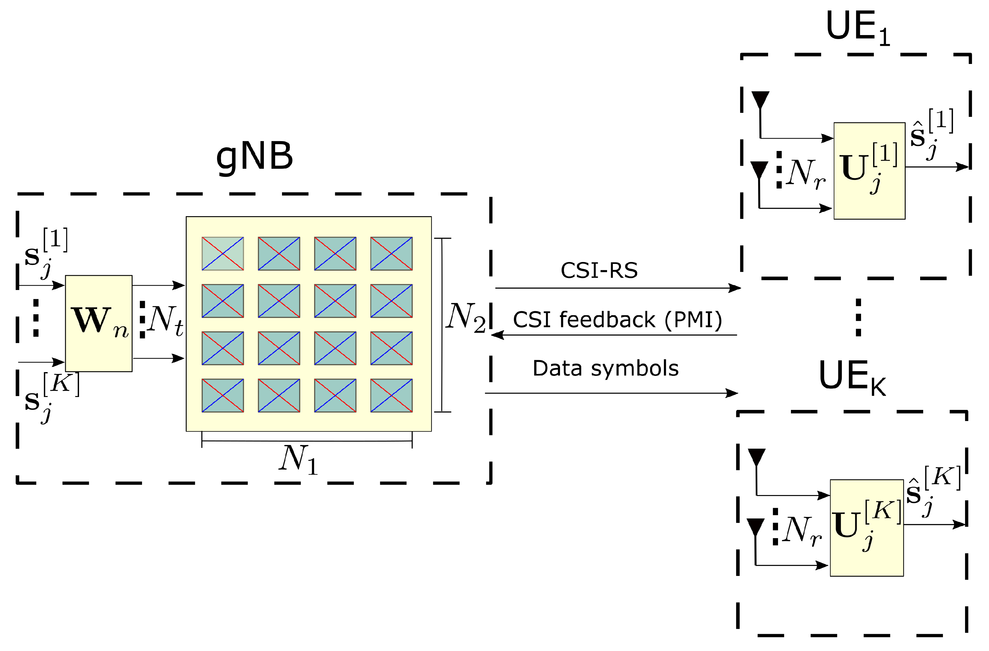
In this section, a general MU-MIMO setting composed of
K UEs is considered as shown in
Figure 1. At each symbol period, the gNB sends
data streams spatially multiplexed to
K UEs. An OFDM transmission with
subcarriers in the frequency domain is assumed. The complex symbols transmitted at the
jth subcarrier are denoted as
. In this equation,
represents the
data streams transmitted to the
kth UE. It is assumed that
. The gNB and each UE are equipped with
and
antennas, respectively.
The OFDM symbols are precoded in the gNB to avoid interference between the UEs. The precoding matrix is designed according to the 5G-NR standard. To avoid large overhead, contiguous subcarriers are grouped in a subband since they are likely to experience a comparable channel effect. The number of subcarriers in each subband is given by
, where
is the number of subcarriers in each physical resource block (PRB) and
is the number of PRB in each subband. Let
denote the set of subbands, where
contains the subcarriers that are in the
nth subband. The total number of subbands
, given by the cardinality of the set
, is defined according to the TS 38-214 [
25]. The subcarriers inside the
nth subband (i.e.,
) are precoded with the same matrix
computed according to the 5G-NR standard. For simplicity, it is assumed that the number of physical transmit antennas is the same as that of virtual antenna ports. Therefore, the precoding matrix is given by
, where
is the precoder related to the
kth UE.
A codebook-based beamforming is considered, according to 5G-NR specifications. Therefore, the precoding matrix is selected from a set of predefined codebooks based on the knowledge that the gNB can acquire from the CSI. Therefore, a codebook-based CSI acquisition procedure is applied [
2]. As illustrated in
Figure 1, the channel is estimated at the UE by measuring known reference signals transmitted from the gNB called CSI reference signal (CSI-RS). A quantized version of the estimated CSI is reported from the UE to the gNB including information about the precoding matrix indicator (PMI) and rank indicator (RI), which identify the best precoding matrix according to the UE measurements. This information is used by the gNB as a recommendation to select the precoding matrix. CSI feedback has been designed in the 5G-NR standard to cover both Type I and Type II codebooks, for SU-MIMO and MU-MIMO, respectively [
25,
39].
The received signal at the
kth UE side is multiplied by the combining matrix
to maximize the signal to interference and noise ratio (SINR). With these considerations, the received symbol vector is expressed as [
6]
where
represents the channel matrix at the
jth subcarrier between the gNB and the
kth UE. Furthermore,
is the circularly symmetric additive white Gaussian noise vector (AWGN) at the
kth UE
. The first term in (
1) represents the desired signal while the second term is the interference produced by the multiplexed UEs that share the same PRBs. The SE at the
jth subcarrier and
kth UE is computed as
where
denotes the SINR at the
jth subcarrier,
kth UE, and
dth data stream,
. For a given precoding and combining matrix, the SINR can be written as [
40]
It must be pointed out that the denominator in (
3) includes the interference terms and also the noise variance, expressed through the covariance matrix
. This is detailed in the following equation where the interference plus noise covariance matrix
is defined as
The major goal of this paper is to evaluate the SE bounds achieved by the precoding matrices designed within the 5G-NR specifications. However, the standard does not specify the combining filter design at the receiver side for downlink data transmission since it is vendor specific based on their own research. In this work, the MMSE combining method is applied to maximize the SINR based on the precoding matrix previously computed at the gNB side [
3,
40]. With this strategy, the highest SE is attained. Nevertheless, the design of the combining matrix is limited by the knowledge that the UE can acquire from the channel. It must be noted that in a multi-user scenario, each UE is only able to estimate its channel to the gNB supported by the CSI-RS. However, a full representation of the channels with the remaining users can not be obtained. Therefore, according to this restriction, the combining matrix is designed as
where the covariance matrix
only considers the channel between the gNB and the
kth UE as follows
The subsequent sections describe the design of the precoding matrix according to the 5G-NR standard for SU-MIMO and MU-MIMO systems.
3. Precoding Matrix Design Based on Type I 5G-NR for SU-MIMO
The design of the precoding matrix according to the Type I codebook for SU-MIMO is described in this section. This is a particular case of the system model described in
Section 2 assuming
. The main goal is to transmit the signal over the
strongest propagation paths of the channel matrix to the target UE. Inter-layer interference is avoided with the precoding matrix designed at the gNB based on the PMI reported from the UE.
Table 1 defines the supported parameters for Type I.
According to TS 38-214 [
25], the gNB is configured with a maximum number of 32 virtual antenna ports for the downlink transmission. Without loss of generality, the virtual antenna ports are assumed to be equal to the physical transmit antennas in this paper. Then
, where
is the number of antenna panels,
and
are the dual-polarized (DP) antenna elements in the horizontal and vertical dimension, respectively, as illustrated in
Figure 1. Note that the product by 2 indicates the use of DP antennas. A single or multi-panel antenna is supported where each panel can be designed following a uniform linear (ULA) or planar array (UPA). Up to
and
layers transmission is available for single-panel and multi-panel, respectively. The maximum number of layers
depends on the number of antenna ports such that
. Since more users are commonly located in the azimuth plane, then a higher number of antennas is available in the horizontal dimension to provide a higher spatial resolution. A maximum number of 16 antenna elements in a single-panel array is supported with a configuration of
,
for ULA or
,
for UPA [
31].
The main objective in Type I is to select
precoding vectors from a predefined DFT-codebook set that corresponds to the strongest propagation paths. The precoding vector for the
dth layer in the
nth subband is designed as
where
and
are related to wideband and subband parameters, respectively. Note that the index
k is omitted in (
7) since a single user is considered in this section. The wideband matrix
is defined as follows
where
indicates the direction of the strongest beam in the
dth layer. This factor is independent of the frequency and polarization since it only depends on large-scale properties of the channel [
31]. Note that since orthogonal polarization is assumed, then the same beam is transmitted over the two sets of DP antennas without causing interference. Consequently,
has a diagonal block structure. For an UPA, the
dth beam
is obtained from a DFT-codebook set as a function of the horizontal and vertical indexes
and
, respectively, as follows [
2,
30]
where
and
are the DFT-based ULA precoders in the horizontal and vertical direction, respectively, given by
In the case of ULA, above expressions are simplified considering index
and
. The terms
and
define the oversampling factors in the horizontal and vertical dimensions, respectively, to obtain a finer spatial granularity. This increases the probability of always being able to steer the beam in a direction close to the UE and hence, the beamforming gain is improved. The beam selection step is obtained by properly selecting the horizontal (
) and vertical (
) indexes from the predefined DFT-codebook set with dimension
. Note that one beam is selected per layer, and the
beams (i.e.,
form an orthogonal basis to avoid inter-layer interference. The orthogonality can be obtained in the horizontal dimension between beams spaced by an integer factor of
, in the vertical dimension between beams spaced by an integer factor of
, or in both dimensions at the same time. The values of
and
are not configurable parameters in NR standard. For UPA,
and for ULA,
( see Table 5.2.2.2.1-2 in TS 38-214 [
25] for details).
On the other hand,
denotes the inter-polarization co-phasing factor which is a frequency-selective subband parameter defined as
Based on the structure of the precoding matrix in (
7), the PMI is divided into the set of indexes
and
that are used for the gNB to compute
and
, respectively, according to the Tables 5.2.2.2.1-5 to 5.2.2.2.1-12 for single-panel and Tables 5.2.2.2.2-3 to 5.2.2.2.2-5 for multi-panel in TS 38-214 [
25]. Each table contains the steps to design the precoding matrix according to the codebook type (i.e., single-panel or multi-panel), the specific antenna array configuration of the gNB given by
, and the number of parallel layers
[
25]. Furthermore, there are two different codebook modes that define the structure of
. Note that
needs to be reported for each subband but
is the same for the entire bandwidth. Thus, feedback overhead is reduced. The next sections describe the design of the precoding matrix for a single and multi-panel array.
3.1. Type I Single-Panel
Type I single-panel codebook is designed assuming that all antennas are grouped into a single panel (i.e., ) with a DP ULA or UPA structure. The wideband PMI index is defined as , where and are mapped into and , respectively. For the case of ULA, is always fixed to 0 and is not reported. Then, the index is used to obtain the relative position of the higher layer beams with respect to in case of . In the other cases (i.e., ), the phase offset of the higher layer beams with respect to is fixed. Finally, the inter-polarization co-phasing factor is obtained with .
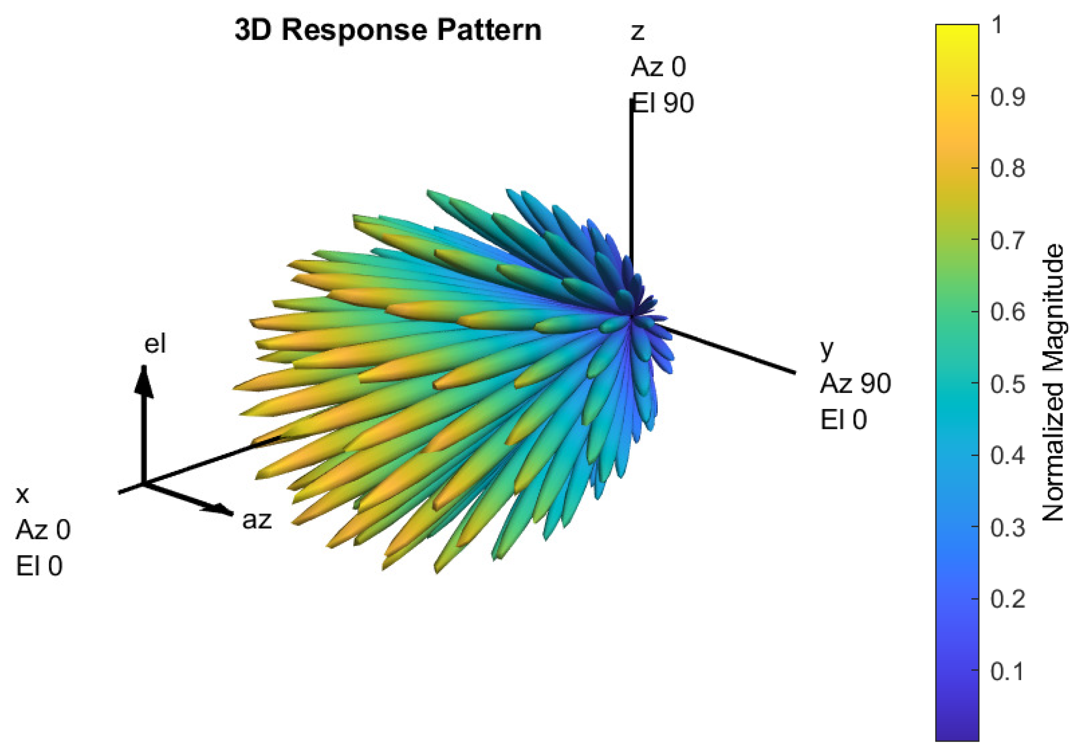
To provide a better understanding of the beam selection procedure,
Figure 2 illustrates the radiation pattern of all the beams that can be obtained with a 5G-NR UPA antenna panel considering
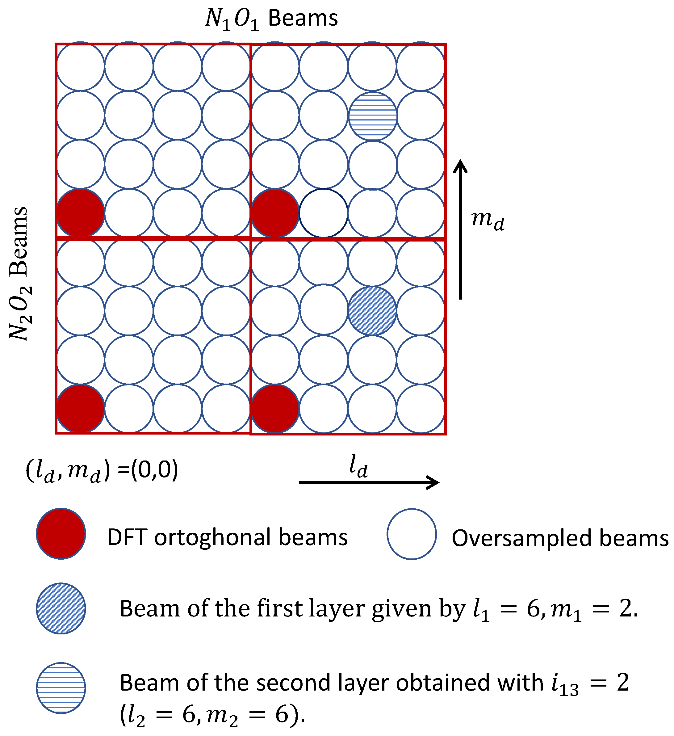
. Each of these beams represents the radiation pattern to a particular angular direction in the azimuth and zenith plane. Then,
Figure 3 depicts a simpler model of this radiation pattern to understand the composition of the DFT grid of beams. Note that this is a representation of the main radiation pattern of each beam without considering the secondary lobes which is a very effective way of illustration used also in [
30,
31]. The grid is composed of a total of
beams. The number of orthogonal DFT beams without the oversampling factors is given by
and they are represented by the red-filled circles. The remaining 60 circles represent the oversampled or rotated beams.
The wideband precoding matrix
selects a beam per layer from the predefined DFT grid. In this example, it is assumed that
,
, and
. The striped circles illustrate the
orthogonal beams that are chosen according to the indexes
and
. The beam of the first layer is obtained with
, and
. Then, assuming that
, the beam for the second layer is given by
, and
(see Tables 5.2.2.2.1-3 and 5.2.2.2.1-6 in TS 38-214 [
25] for details). It can be noted that the beams are orthogonal in the vertical dimension. Finally, these two beams are combined with the co-phasing factors selected per subband. Note that the UE only needs to report the coefficients and co-phasing factor of the beam in the first layer. Then, the gNB is capable of computing the beams and the co-phasing factors for the remaining layers. This strategy reduces feedback overhead guaranteeing an efficient transmission.
Commonly, the same matrix
is used for the entire bandwidth. However, codebook mode 2 enables a special case for
or
where
may vary for different subbands. In this case, the selected beam also depends on the frequency-selective coefficient
. This represents a more flexible design at the cost of requiring more bits for reporting
. Therefore, it is only implemented for a low number of layers (i.e.,
or
) to ensure that the overhead is not too high. There is another special design of the matrix
enabled for
when
or
. The main goal is to prevent the beam in the horizontal dimension from becoming narrower as the number of antenna ports increases, which can be harmful to some propagation models. Therefore, the available values of
are reduced to
to widen the beam [
25,
31].
3.2. Type I Multi-Panel
The precoding matrix design for multi-panel antenna arrays is just an extension of Type I single-panel. In this case, the wideband PMI index is defined as , and the frequency-selective index is . The main problem with using several antenna panels is that the distance between two consecutive antennas of different panels does not have to be equal to the spacing between two consecutive antennas in the same panel. Therefore, the assumption of uniform arrays is no longer fulfilled. To solve this problem, the beamforming design is based on the assumption that all antenna panels are identical. Each panel is composed of antenna elements in the horizontal direction and in the vertical direction. Then, the idea is to design the precoding matrix for a single-panel. Finally, this matrix is repeated in the remaining panels but adding a phase offset , where , to compensate the non-uniform distance between panels.
Currently, the precoding matrix can be obtained according to two different codebook modes supporting the spatial multiplexing up to 4 parallel layers. The codebook mode 1 supports both
and
. The co-phasing between each panel is obtained using only wideband coefficients. On the contrary, in the case of codebook mode 2, the co-phasing is configured by applying a combination of wideband and subband parameters. This mode is only supported for two antenna panels. In general, the precoding vector for the
nth subband and
dth layer can be written as
where
The phase offset
is computed according to the wideband sub-index
in codebook mode 1, such that
, where
. The coefficients for the higher layer are also adjusted based on the subindex
to obtain an orthogonal precoding matrix.
4. Precoding Matrix Design Based on Type II 5G-NR for MU-MIMO
In this section, the design of the precoding matrices based on the Type II codebook is described. The main idea is to support communication to multiple UEs that share the same PRBs in MU-MIMO systems. In this case, a more sophisticated precoding design is required to cancel the interference in the spatial domain between the UEs at the cost of higher feedback overhead. In Release 15, only 2 data streams per UE are supported. However, enhanced precoding strategies are proposed in Release 16 to provide a finer frequency granularity supporting up to 4 layers and reducing signal overhead. Type II is only designed for single-panel antenna arrays with the configurations defined in Table 5.2.2.2.1-2 [
25].
The main characteristic of Type II is that it applies a linear combination of
L orthogonal beams per layer instead of just selecting the strongest one as in Type I. This strategy provides a more accurate representation of the dominant eigenvectors of the channel to obtain a precoding matrix that avoids interference between the UEs. Similar to Type I, this design can be represented as a two-step procedure for the
kth user and
dth layer denoted by
. However, in the case of Type II codebook, the wideband matrix
represents an orthogonal basis composed of
L beams per polarization and layer, where
. Then, a linear combination of the chosen beams is performed by using
which is comprised of wideband and subband complex coefficients. With this design, the desired signal is coherently combined at the receiver side, while the interference signal from co-located UEs is canceled improving the SINR [
2,
30].
The wideband matrix for the
kth user and
dth layer is obtained as
where
is composed of
L beams obtained from a predefined DFT-codebook. Note that
,
, is defined in (
9) for the
dth layer and
kth UE based on a given horizontal (
) and vertical (
) indexes. The beams in
form an orthogonal basis to avoid inter-layer interference. Similar to Type I, the orthogonality can be obtained in the horizontal, vertical, or both dimensions at the same time.
The PMI index set to obtain the wideband and subband matrices is defined as
, and
, respectively. The dimension of each subindex is given by
,
,
,
,
, and
. Note that a higher overhead is required than in Type I. The computation of the wideband matrix
is performed according to the
index vector. The first problem of this design arises due to the long feedback required to identify the
L beams for each layer and polarization. The main solution to reduce overhead is to first select
L DFT orthogonal beams based only on the information reported in the
subindex. The algorithm proposed in section 5.2.2.2.3 of TS 38-214 [
25] selects the
L beams based on a binomial coefficients computation. Then, to increase the granularity, these DFT beams are oversampled in the horizontal and vertical dimensions by the subindex
. The same rotated factors are used for all the
L DFT beams to reduce feedback overhead.
Then, these selected
L beams are linearly combined with different amplitude and phase weights for each layer and polarization according to
as follows
where
and
represent the wideband and subband amplitude coefficient, respectively, for the
dth layer and
kth UE. The wideband amplitude parameter
is computed from the subindex vector
which is quantized with 3 bits. Therefore, each element of
takes values from the set
. The subband amplitude coefficients
are selected from the set
according to the subindex
that uses a single-bit quantization to reduce overhead.
On the other hand, denotes the inter-polarization co-phasing vector. Similarly to Type I, each value of is given by the complex exponential . The phase values are obtained from an -phase-shift-keying (PSK) alphabet, where , according to the subindex vector .
In Release 16, the Type II codebook is enhanced to support a higher number of parallel layers (i.e.,
) and a more accurate representation of the channel eigenvectors. In this sense, the amplitude and phase coefficients are obtained with a higher number of quantization bits. Furthermore, the frequency granularity is improved by the introduction of the "frequency domain (FD) units" concept. Consequently, the precoding matrices are designed per FD instead of per subband as in Release 15. Since the number of FD units can be twice the number of subbands, the frequency granularity can be improved by a factor of 2. However, this demands a higher CSI-RS feedback overhead. To overcome this problem a DFT-based compression technique has been proposed. For this purpose, the wideband
and linear combination
matrices reuse the same design concept of Type II codebook in Release 15 but they are providing the results per FD units. Moreover, an additional matrix is defined to perform the frequency compression
of certain DFT basis vectors from the total of FD units. Furthermore, to keep the CSI overhead controllable, either a one step or two steps feedback scheme is used based on the number of FD units. In Release 17, the angles and delays reciprocity in FDD operation are exploited to reduce computation complexity at the UE side. In addition, enhancements of multiple transmission and reception point (mTRP) are addressed [
26,
29,
32].
5. Simulation Results
In this section, the SE bounds achieved by the 5G-NR precoding matrices are evaluated for SU-MIMO and MU-MIMO scenarios. Simulation results are obtained in MATLAB by using a CDL channel model with a delay spread of
s, and a maximum Doppler shift of 50 Hz. A delay profile CDL-C defined according to TR 38-901 is assumed [
38]. A different offset in the angles of departure in the azimuth (AoD) and zenith (ZoD) dimensions is added to each UE to simulate a deployment of
K users randomly distributed with uniform probability within a circular coverage area. It is assumed that the gNB is located at a height of 30 m in the center of the circle. Then, the UEs are spread in the azimuth dimension between
and within a radio between 50 and 500 m from the gNB. The simulation results are averaged over 50 time slots and 100 random distributions of the UEs. The typical 5G-NR numerology is used for simulation as illustrated in
Table 2.
Without loss of generality, the transmission power of the gNB is normalized to . This work is mainly focused on obtaining the SE bounds of the 5G-NR precoding matrices assuming a downlink data transmission. Therefore, the power control mechanism for different UEs is not considered. At each experiment, the PMI is obtained at the UE side by evaluating all the precoding matrices that can be computed according to the 5G-NR standard for a given antenna array configuration and a value of . Finally, the PMI corresponding to the matrix that achieves the highest SINR is selected. For simplicity, codebook mode 1 is considered for the simulations.
5.1. SE Bounds Achieved by Type I Codebook
In this subsection, the performance bounds of the Type I codebook are evaluated for SU-MIMO systems. The SE is obtained averaging over all the subcarriers as
, where
is the SE per subcarrier defined in (
2).
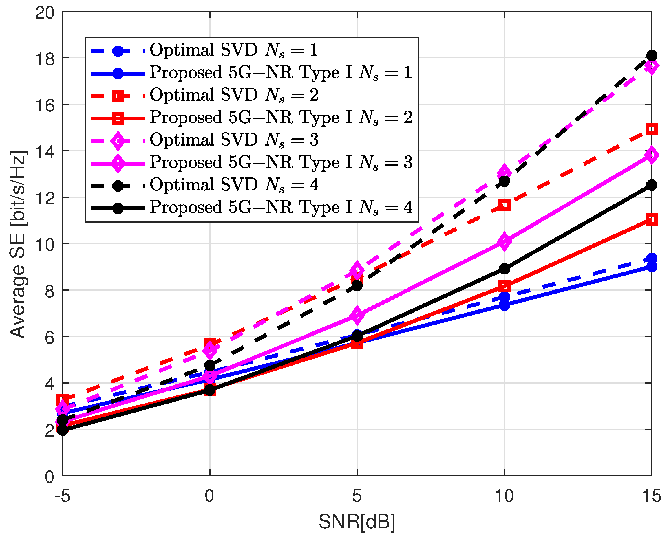
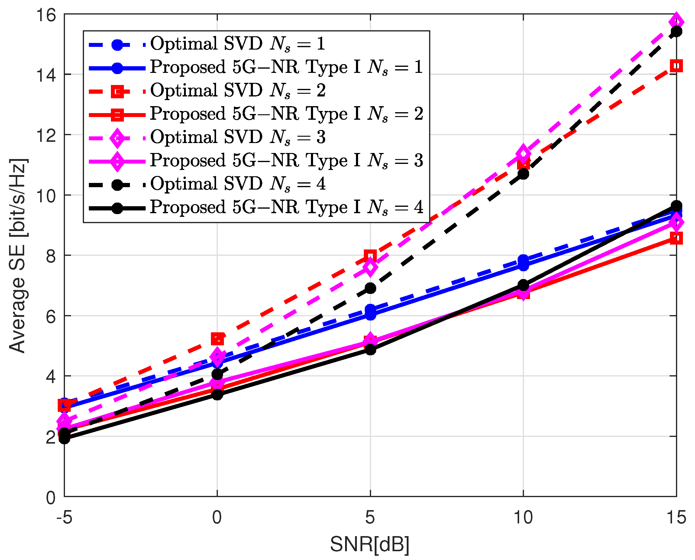
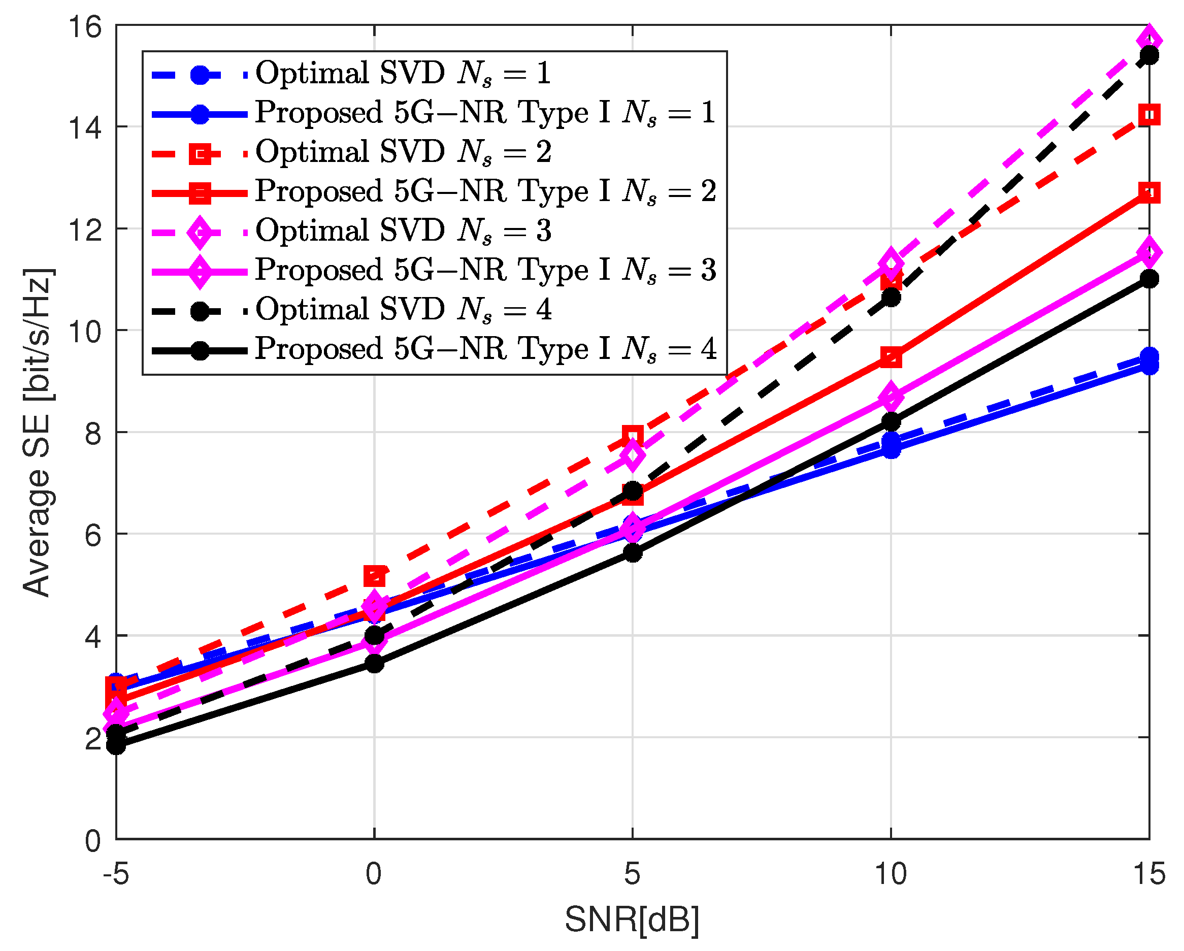
Figure 4,
Figure 5 and
Figure 6 illustrate the average SE for a range of SNR between −5 and 15 dB and assuming different antenna configurations at the gNB. The number of receive and transmit antennas is set to
, and
(i.e., 8 CSI-RS antenna ports), respectively. Therefore, the maximum number of parallel layers allowed is
.
Figure 4 and
Figure 5 are obtained for a single-panel antenna array with
,
(i.e., ULA ), and
,
(i.e., UPA), respectively.
Figure 6 depicts the performance achieved by a multi-panel antenna array with
.
The results obtained with the 5G-NR design are compared with the optimal solution given by the SVD of the channel matrix which serves as a benchmark [
5]. It can be noted that for all the configurations shown, the performance of the SVD is better than 5G-NR solution at the cost of perfect knowledge of the channel matrix at both the gNB and UE sides. This is not a practical assumption in real scenarios as it would require an unfeasible overhead. On the contrary, the 5G-NR solution is designed to achieve a trade-off between performance, low overhead, and complexity. Therefore, since the gNB computes the precoding matrix based on a predefined codebook set and using the PMI index transmitted from the UE, the performance is degraded in comparison to the optimal SVD solution. However, the overhead is significantly reduced because only a few bits are required to transmit the PMI. In order to illustrate the complexity and overhead advantages of 5G-NR over SVD, a practical example will be shown. According to TS 38-212 [
39] and TS 38-214 [
25], in the case of single-panel ULA with
and
, the PMI requires 6 bits to report the wideband parameters and a single bit per subband to feedback the frequency selective coefficients. Since
, a total of 19 bits are used to compute the precoding matrix. On the contrary, for the same gNB configuration, the SVD needs to report an
matrix with complex coefficients from the UE to the gNB. Assuming an 8-bit quantization, a total of 6656 bits must be fed back. This amount of bits to report the CSI from the UE to the gNB is not affordable in practical applications because it leads to several drawbacks. First, the probability that the CSI will be correctly decoded by the gNB is lower than with smaller report sizes. Therefore, packet segmentation at the UE side might be needed. This means that the report is fed back in different scheduling periods which will introduce more latency and complexity. Moreover, packet retransmission could be a necessity and the delay in the network will be increased. It can be noted that a higher number of parallel layers does not always translate into a higher SE. The value of
that achieves the highest performance depends on the channel matrix, antenna configuration, and the value of SNR. Therefore, the UE reports to the gNB the RI of the precoding matrix that corresponds to the value of
that attains the highest SE. In general, for low SNR values, it is better to concentrate the energy in a single very directional path to the UE. In this example, the values of
that achieve the highest performance averaging over all the SNR range, for the single-panel ULA, UPA, and multi-panel ULA are
, and
, respectively. According to these figures, the best performance is obtained with the ULA configuration. The reason for this is that, in this case, the UPA layout has few antennas in each dimension, which does not properly exploit the spatial characteristics of the channel.
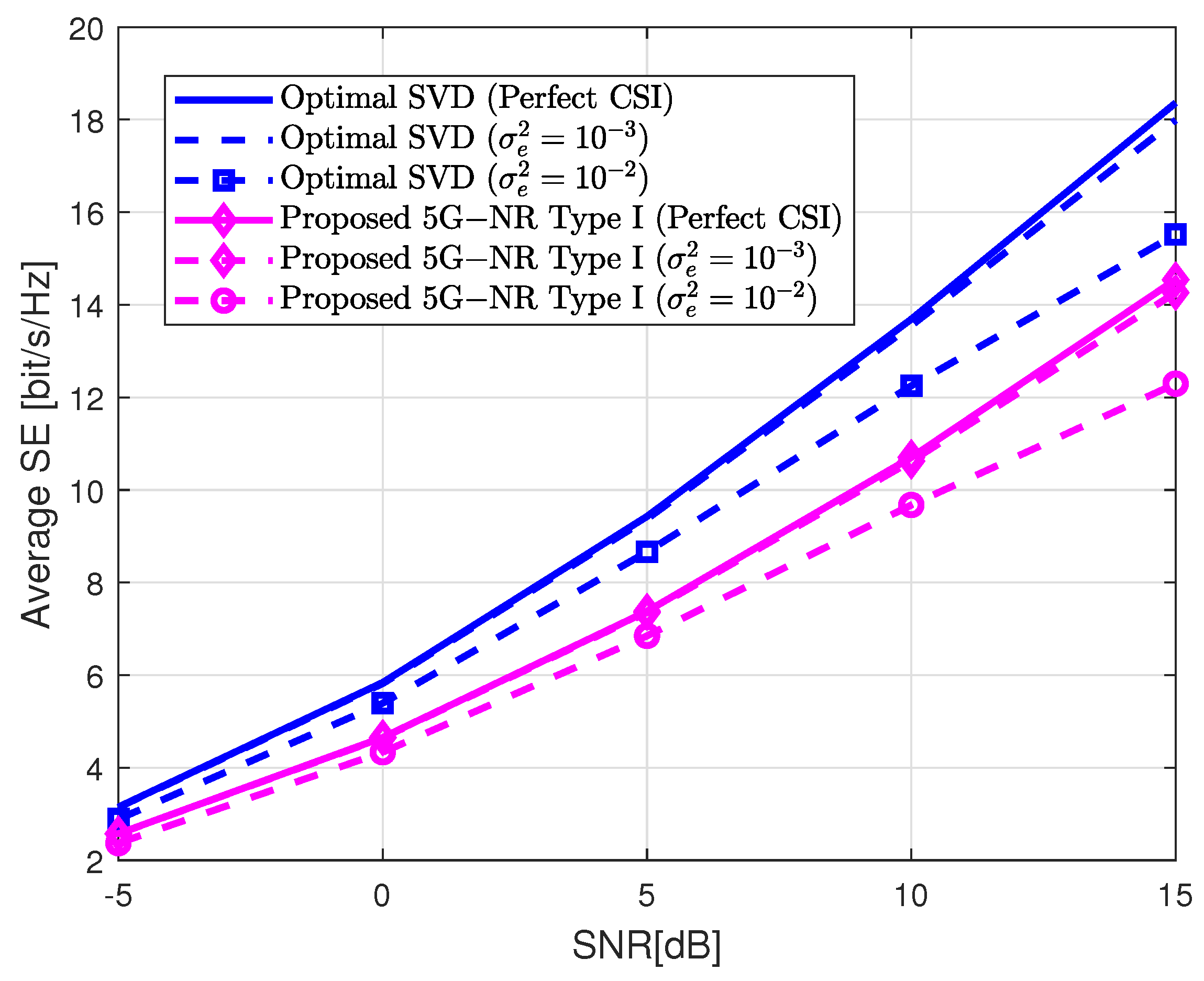
Figure 7 shows the robustness of the 5G-NR precoding matrices in the presence of channel estimation errors. This result is obtained by adding an error matrix
to the true channel
as
. Each element of
follows a Gaussian distribution with zero mean and variance
. The performance loss is evaluated for two different error variances,
and
, which are common values for channel estimation algorithms. The gNB is configured following the ULA layout used in
Figure 4. According to the results of
Figure 4, the number of parallel layers is now fixed to
. It can be noted that the channel estimation error affects the 5G-NR precoding performance in the same proportion as the optimal SVD solution. The performance degradation is negligible for
. In the case of
, the performance loss is only noticeable for high values of SNR. This is due to the fact that the effect of noise is more relevant than the channel estimation errors for low SNR.
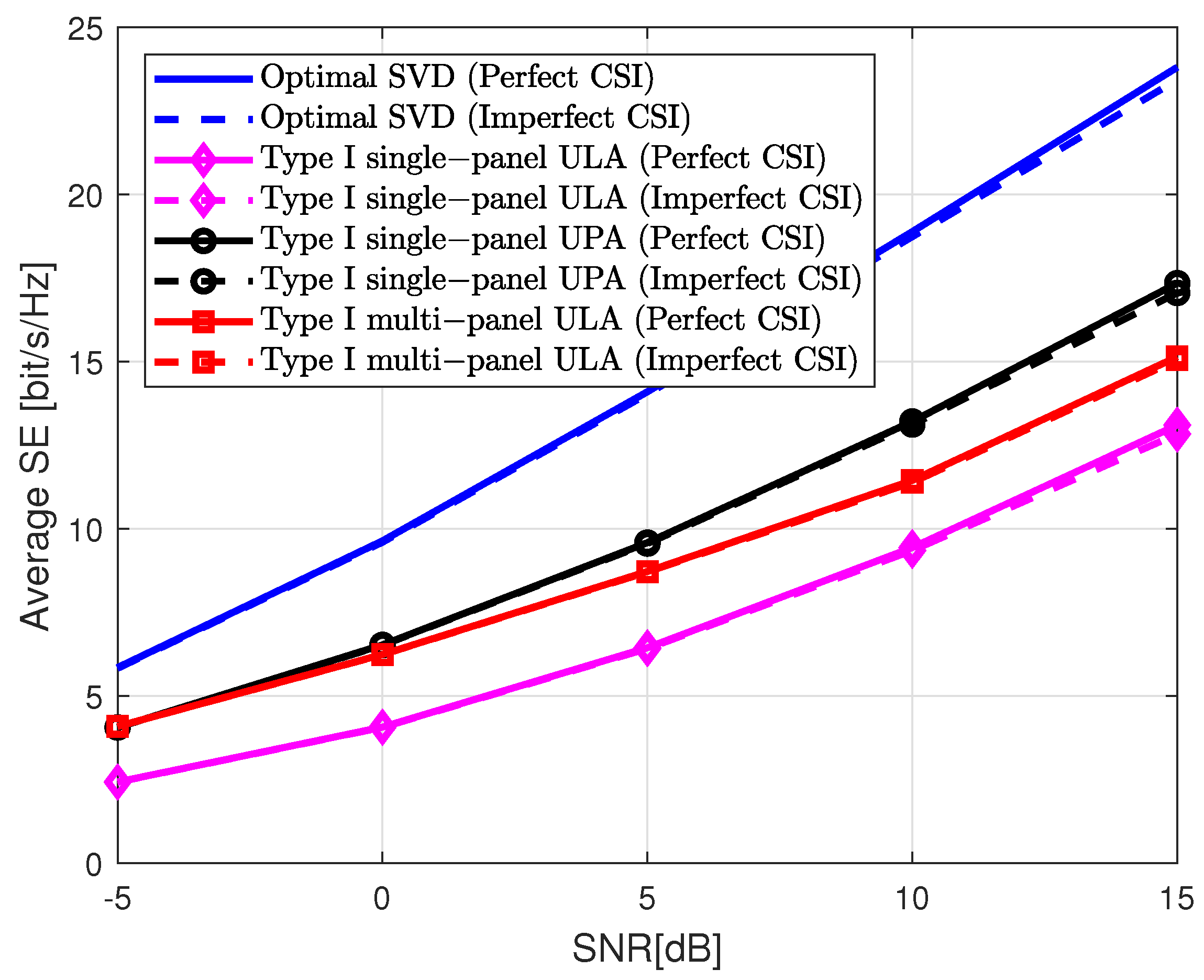
Figure 8 depicts the average SE for a higher number of transmit antennas given by
( i.e., 32 CSI-RS antenna ports). The performance is evaluated for several values of
. Similar to the previous figures, three types of different antenna configurations are considered, including both single and multi-panel arrays. A single-panel ULA and UPA are considered with
, and
,
, respectively. Furthermore, a multi-panel is considered with
, and
. This figure shows the SE gain obtained with respect to
Figure 4,
Figure 5 and
Figure 6 when increasing from 8 to 32 antenna ports. The performance loss due to channel estimation error is also evaluated considering
. Similar to
Figure 7, the degradation in SE is only slightly noticeable for SNR values higher than 10 dB. Regarding the overhead between linear and planar arrays, ULA demands lower overhead because the subindex
is not reported. For this particular example, the single-panel ULA requires a PMI with a total of 20 bits while single-panel UPA needs 22 bits. It must be pointed out that the multi-panel ULA also needs to report the subindex
and hence, 22 bits of overhead are used as in the case of single-panel UPA [
25,
39]. However, the computational complexity is higher in UPA because a DFT precoder is computed in both dimensions. Then, the Kronecker product is applied in (
9) to obtain the final wideband precoding matrix. On the contrary, these expressions are simplified in ULA since only a DFT precoder in one dimension is required. Although the complexity and overhead are higher in UPA, its performance is superior since the beams can be steered in horizontal and vertical directions. It must be noted that the highest SE in
Figure 8 is obtained with the UPA configuration because the number of antennas in both dimensions becomes higher and hence, the spatial properties of the channel are better exploited.
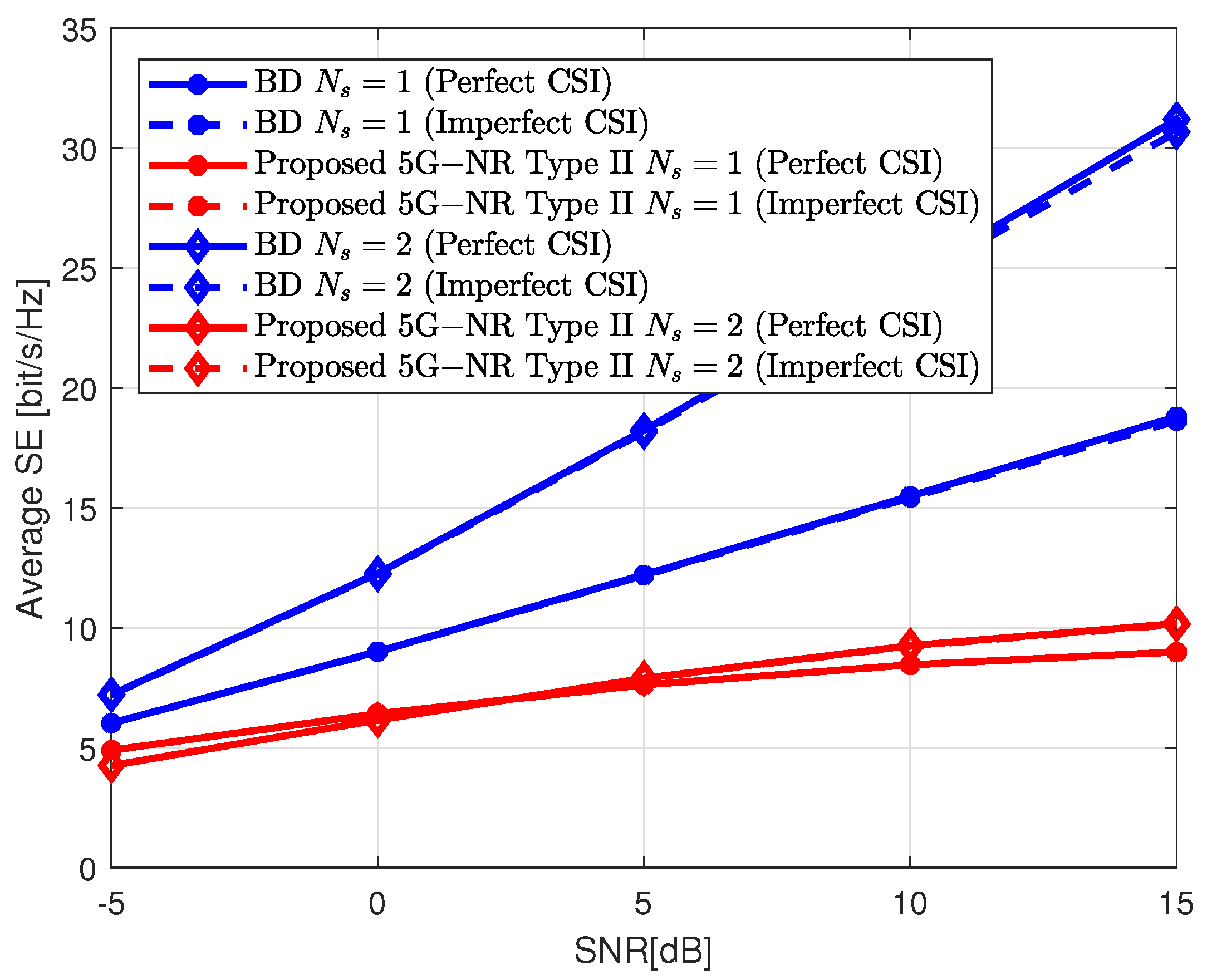
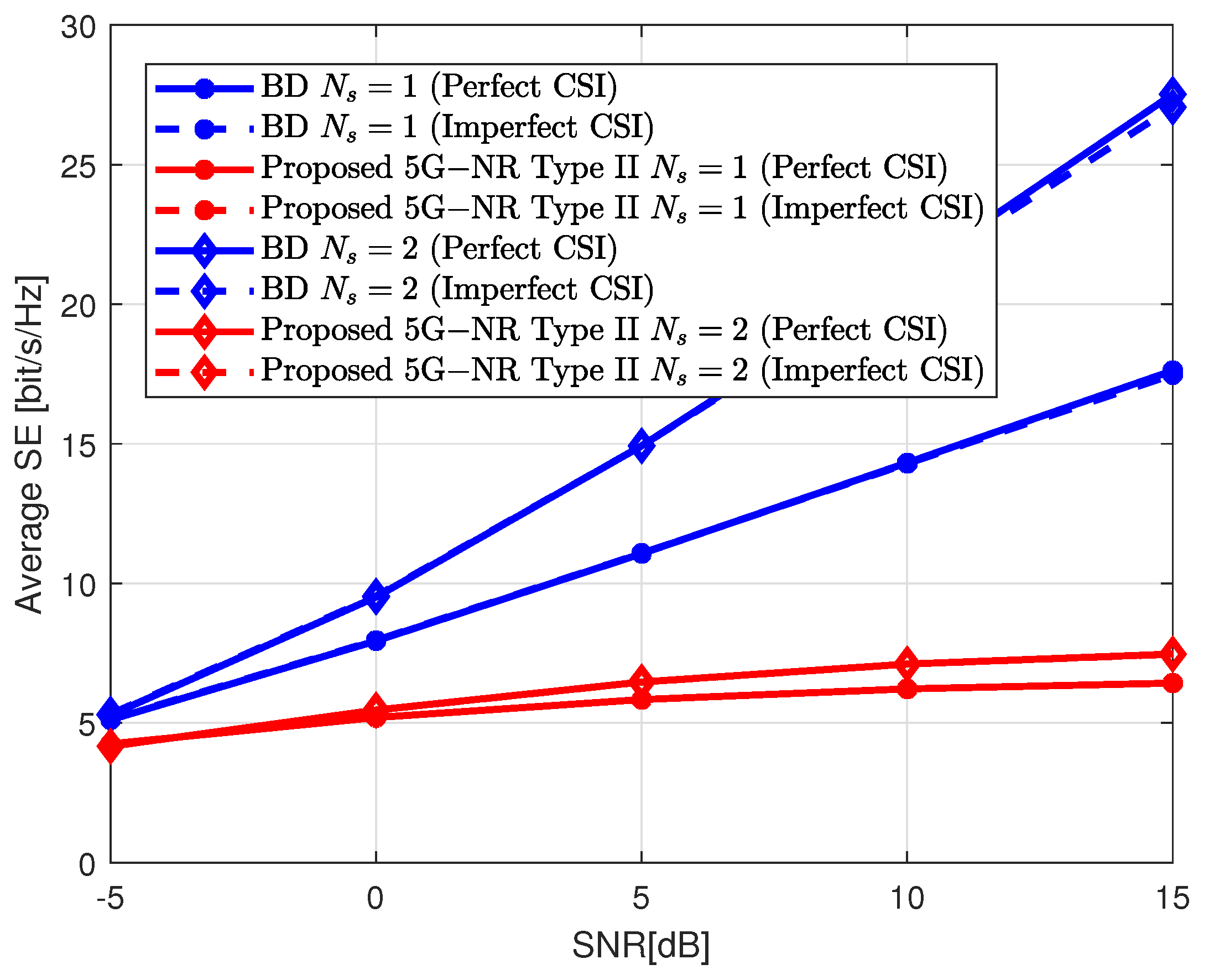
5.2. SE Bounds Achieved by Type II Codebook
In this subsection, the performance obtained with the Type II codebook for MU-MIMO scenarios is illustrated. The total SE of the network is measured as
, which is known as sum-SE. The sum-SE achieved by the 5G-NR precoding matrices is compared with the theoretical block-diagonalization (BD) method described in [
37]. This method is designed to remove the interference signals and maximize the SINR in (
3) based on the knowledge of the channel matrix of all UEs. A perfect and imperfect CSI with
are assumed. In the case of 5G-NR, two beams per layer and polarization (i.e.,
) and a QPSK alphabet (i.e.,
) are considered.
Figure 9 illustrates the SE bounds assuming
, and
. The gNB is implemented following a single-panel ULA with
, and
.
Figure 10 shows the performance for the same scenario but considering a single-panel UPA with
, and
. In both cases, the SE of the 5G-NR is saturated for high SNR values. This is because interference is the limiting factor that avoids performance enhancement. It should be noted that the overhead in Type II is much higher than in Type I. For this particular example, assuming
and the single-panel ULA configuration, 22 bits are required to report the wideband coefficients while 9 bits per subband are needed for the frequency selective parameters. Therefore, a total of 137 bits per UE is required to report the PMI. In the case of UPA, two extra bits are required for the wideband parameters which leads to a total of 139 bits per UE. Similar to the Type I codebook, the effect of the channel estimation errors with
hardly influences the SE results.
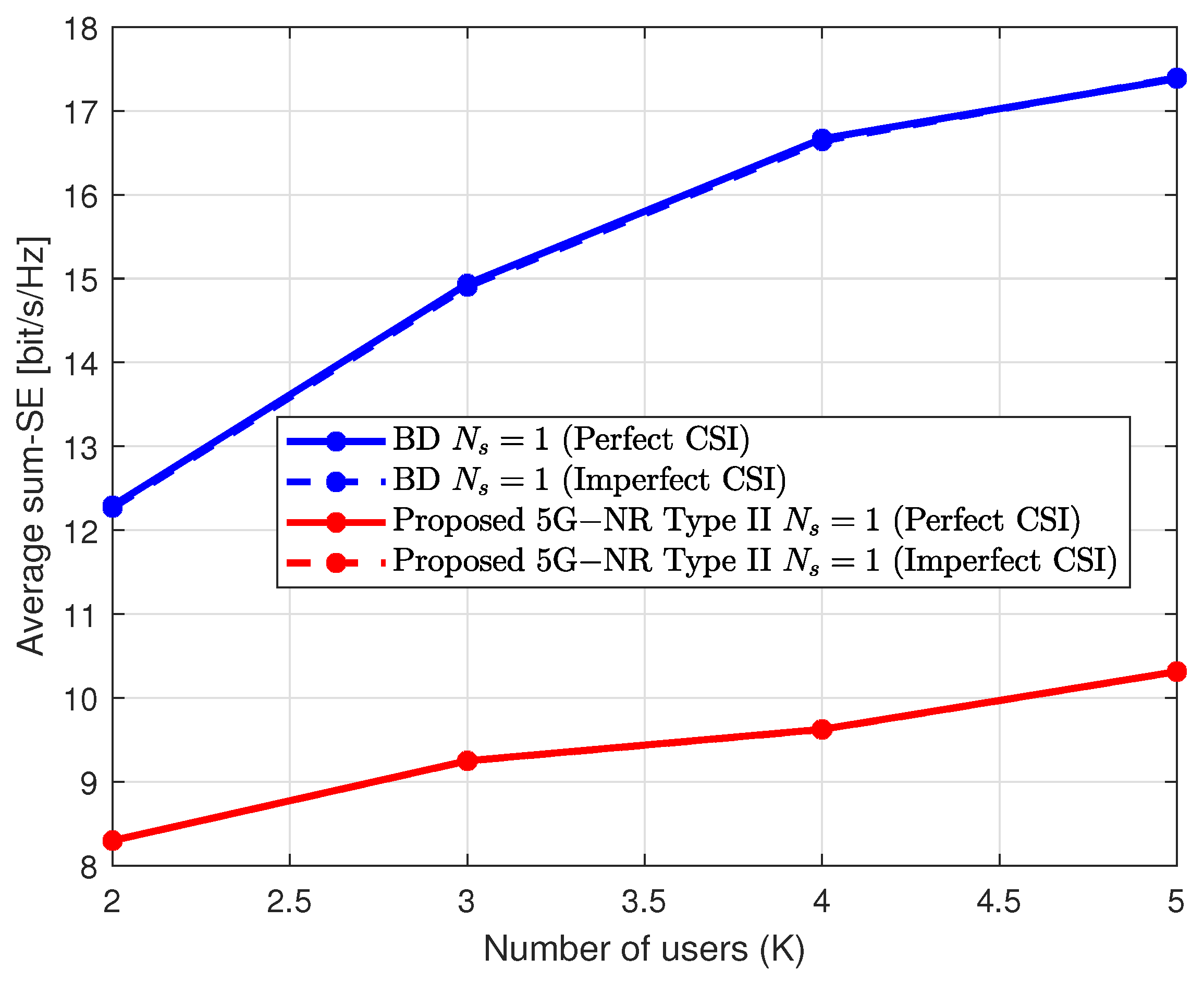
Figure 11 shows the sum-SE for different numbers of multiplexed UEs with the same PRBs. The higher the value of
K, the higher the interference signals which limits the sum-SE performance increment. The correlation between the channel matrices of the different users influences the interference cancellation. Consequently, Type II codebook is only applicable to those users with low spatial correlation.

 ,
, 


