Article

A Cooperative Control Strategy for a Hydraulic Regenerative Braking System Based on Chassis Domain Control

1
School of Intelligent Manufacturing, Taizhou University, Taizhou 318000, China
2
U POWER Technology, Shanghai 200233, China
3
Geely Technology Group, Hangzhou 311228, China
4
Chongqing Jinkang Seres New Energy Vehicle Research Institute Co., Ltd., Chongqing 400000, China
5
School of Mechanical Engineering, Zhejiang University of Technology, Hangzhou 310014, China
*
Author to whom correspondence should be addressed.
Electronics 2022, 11(24), 4212; https://doi.org/10.3390/electronics11244212
Submission received: 20 October 2022 / Revised: 4 December 2022 / Accepted: 13 December 2022 / Published: 16 December 2022

Abstract

:
In order to solve the problems of wheel locking and loss of vehicle control due to understeering or oversteering during the braking energy-recovery process of the hydraulic regenerative braking system (HRBS), aiming at the characteristics of chassis domain control that can realize coordinated work among various chassis systems, a cooperative control strategy of HRBS based on chassis domain control was proposed. Firstly, a HRBS test bench was built, and the accuracy of the simulation model was verified by comparing it with the test. Next, the proposed cooperative control strategy was designed, which coordinates the wheel anti-lock actuation system (WAAS) to adjust the wheel cylinder pressure to solve the wheel locking problem of HRBS in the process of braking energy recovery and coordinate the vehicle anti-loss control actuation system (VACAS) to generate a yaw compensation moment to solve the vehicle loss of the control problem of HRBS in the process of braking energy recovery by detecting the wheel slip ratio, yaw rate and sideslip angle. Finally, the established control strategy was verified through the co-simulation of Carsim and Matlab software, and the results showed that the control strategy proposed in this paper could not only avoid wheel locking and loss of vehicle control during turning braking on low-adhesion roads, but also improve the energy-recovery efficiency by 29.64% compared with a vehicle that only controls the slip ratio.

1. Introduction

Relevant studies have shown that approximately 1/3 to 1/2 of energy that is used to directly drive vehicles under urban driving conditions will be dissipated in the process of braking, leading to energy waste by emission to the atmosphere in the form of heat energy [1,2]. HRBS can be used to recover the kinetic energy of vehicles and convert it into hydraulic energy in order to store it in the accumulator. When a vehicle starts or accelerates, the stored hydraulic energy is released in the form of kinetic energy to provide auxiliary power for the vehicle; thereby, the energy is fully utilized and the energy-utilization rate of the vehicle is effectively improved [3,4]. HRBS has been favored over the years due to high power density and high energy-recovery efficiency.
HRBS, in the process of braking-energy recovery, will produce additional torque on the wheels [5,6,7], which will affect the braking performance of the vehicle and may even lead to wheel locking or cause the vehicle to lose control due to understeering or oversteering [8,9,10]. Therefore, how to effectively and fully recover braking energy while solving the problem of wheel locking and the loss of vehicle control during braking is an urgent problem to be solved in the research process.
Kim et al. [11] proposed a compound braking torque-distribution method based on fuzzy control theory, and designed a control strategy for the coordination between compound braking torque and ABS. Through verification, it was concluded that this strategy could make the vehicle show better stability and energy-recovery efficiency. Krueger et al. [12] established a cooperative control strategy of regenerative braking and ABS to control the output of regenerative braking force and mechanical braking force by analyzing the wheel slip ratio; the simulation results showed that the strategy had good braking stability and energy-recovery efficiency. By estimating the longitudinal friction of road and tire, Le Solliec et al. [13] implemented distributions of electro-hydraulic composite braking torque through the wheel slip ratio so that the regenerative braking and ABS could work in harmony and effectively improve the braking stability of vehicles. Savitski et al. [9] proposed a strategy of feedforward gain scheduling and proportional-integral feedback for pure-electric dual-axle vehicles to continuously control the regenerative braking system and ABS system to shorten the oscillation time of braking deceleration and improve the braking stability. Aksjonov et al. [14] proposed using the fuzzy logic controller to adjust the regenerative braking torque generated by the motor to achieve accurate control of the wheel slip ratio and maximize the recovered energy on the basis of the longitudinal deceleration of the vehicle. Zheng et al. [15] proposed a strategy model of regenerative braking and ABS cooperative control, in which the brake-pedal displacement and battery SOC were considered as inputs, and the ratio of the electrical mechanism force and the total demand braking force were considered as outputs; modeling and simulation were performed and validated under the road conditions of low-, medium- and high-adhesion coefficients. Mao et al. [16] established a regenerative braking force distribution strategy of anti-lock braking prediction in order to retain the maximum energy-recovery efficiency when the wheel had no locking trend. Once a wheel was locked, the regenerative braking torque was actively switched to delay the intervention time of ABS, and the control strategy was verified by simulation. The abovementioned discussions mainly focus on the control strategy between ABS and the regenerative braking system, in which ABS only prevents the wheel locking during the braking process, but when the vehicle is out of control due to understeering or oversteering, ABS is unable to control it; at this time, ESP needs to intervene. At present, there is relatively little research on the control between ESP and the regenerative braking system, so it is important to study the cooperative control strategy of the regenerative braking system considering wheel locking and the loss of vehicle control.
In this paper, the working principles of HRBS, ABS and ESP were studied, and it was pointed out that the current HRBS, only considering the wheel slip ratio, can only prevent wheel lock during braking; when encountering complex working conditions, the vehicle has a tendency to understeer or oversteer, leading to the loss of control. In order to solve the abovementioned problems, the authors proposed a cooperative control strategy of HRBS based on chassis-domain control, which coordinates the work of each system by detecting the wheel slip ratio, yaw rate and sideslip angle to solve the problems of wheel locking and loss of vehicle control in the process of braking-energy recovery.

2. Establishment HRBS Simulation Model

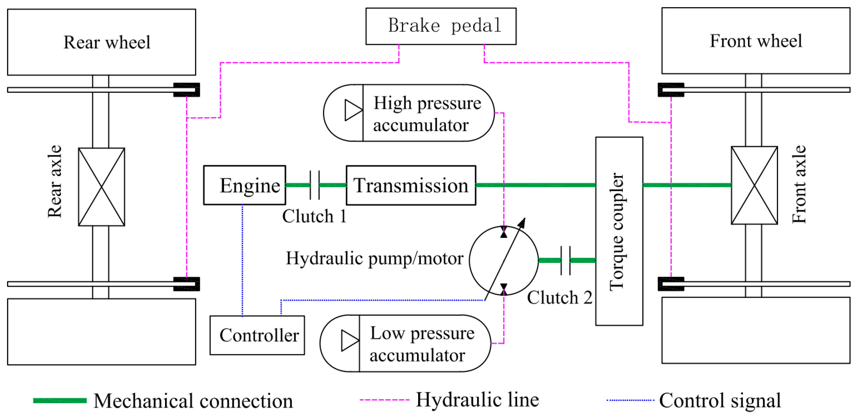
2.1. Working Principle of HRBS

The HRBS is mainly composed of a motor, transmission, clutch, torque coupler, hydraulic pump/motor, low-pressure accumulator, high-pressure accumulator and controller, etc. It is a kind of parallel structure, that is, on the basis of the original power of the vehicle, achieved through the torque coupler’s parallel set of hydraulic power systems; two sets of power systems can work together and can work independently of each other. The working principle is shown in Figure 1. When it works, the secondary element (hydraulic pump/motor) is switched to the motor condition and the oil stored in the high-pressure accumulator is released. The high-pressure oil drives the hydraulic pump/motor to rotate and transmits the power to the torque coupling through clutch 2 and couples with the power transmitted from the engine to the front axle, thus driving the vehicle. When clutch 1 is disconnected, the vehicle is driven by the HRBS alone. When braking, the secondary element switches to the hydraulic pump condition, and the front wheels drive the hydraulic pump/motor through the torque coupler and clutch 2, pumping the oil from the low-pressure accumulator to the high-pressure accumulator and storing it, thus realizing the conversion and storage of kinetic energy to hydraulic energy of the vehicle. At the same time, in the process of recovering braking energy, the HRBS generates braking torque, which acts as a deceleration mechanism for the vehicle.

2.2. Mathematical Model of Hydraulic Pump/Motor

During the braking/driving process, the torque provided by the secondary element (hydraulic pump/motor) is calculated as follows [4]:
T p = p q 2 π η m × 10 6
where T p is the torque generated by the secondary element, N∙m; η m is the mechanical efficiency of the secondary element; p is the work pressure of the secondary element, MPa; and q is the secondary element displacement, mL/r.
The torque of the secondary element is transmitted to the wheel through the torque coupler, differential and reducer, and the final wheel speed and torque are as follows [4,17]:
T r e b = T p i 0 i 1
n w = n p i 0 i 1
where T r e b is the wheel torque supplied by the secondary element, N∙m; i 0 is the torque coupler transmission ratio; i 1 is the differential transmission ratio; n p is the angular speed of the secondary element, r/min; and n w is the angular speed of the wheel, r/min.

2.3. Mathematical Model of Hydraulic Accumulator

According to Boyle’s law, the hydraulic accumulator pressure and volume have the following relationship [4,17]:
p 0 V 0 n = p 2 V 2 n = p V n = c o n s tan t
In the process of braking energy recovery, the energy stored in the hydraulic accumulator is obtained by the following equation:
E a c c = p 0 V 0 n 1 [ ( p 0 p 2 ) 1 n n 1 ]
where p 0 is the hydraulic accumulator initial pressure, Pa; p 2 is the hydraulic accumulator maximum working pressure, Pa; V 0 is the hydraulic accumulator initial volume, m3; n is the gas variability index, and if it represents the isothermal process, then n = 1. Otherwise, it equals 1.4 for an adiabatic process; E a c c is the energy stored in the hydraulic accumulator, J.
The SOC of accumulator pressure is S O C = P P 0 P 2 P 0 , and P is the current pressure of the accumulator, Pa.

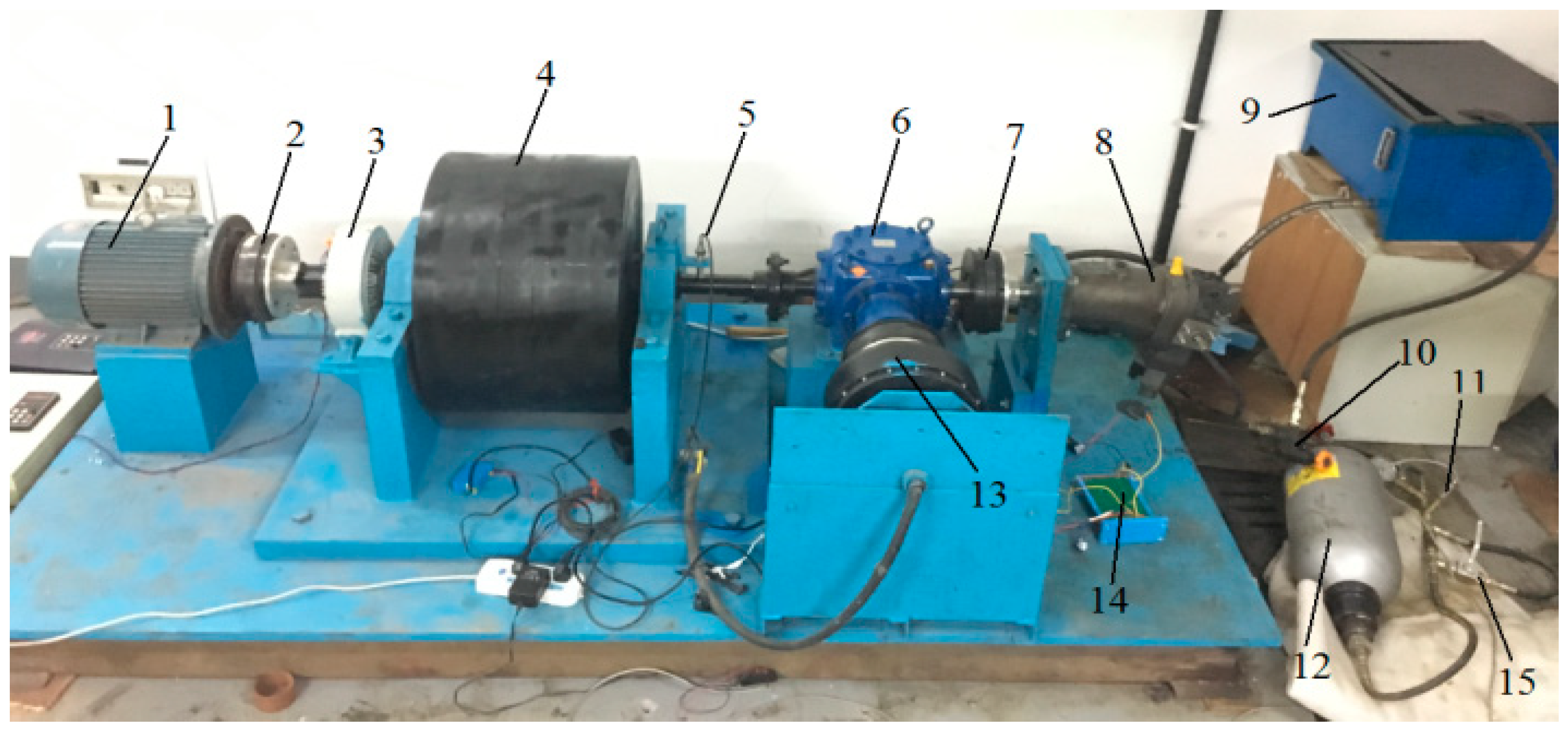
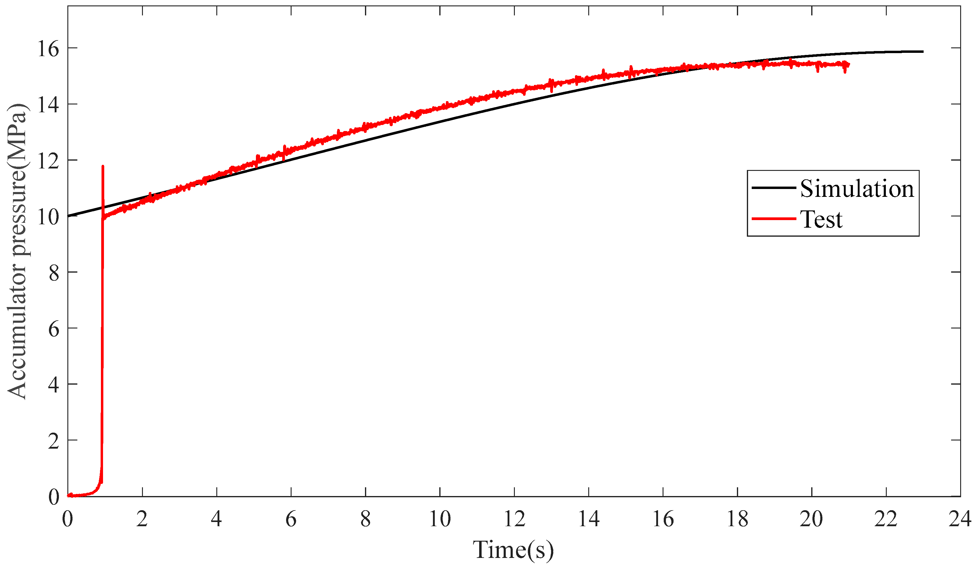
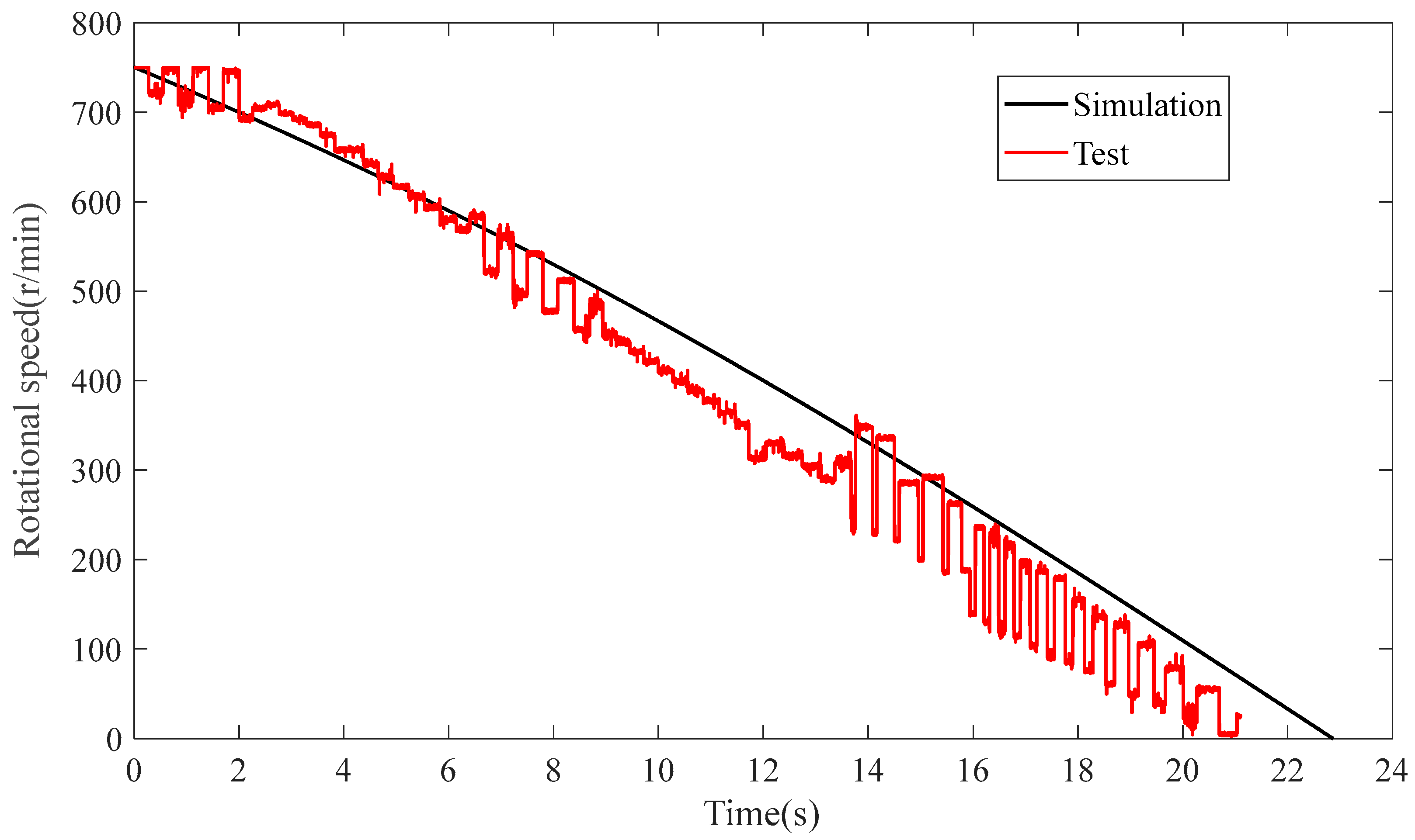
2.4. Validation of HRBS Model

In order to validate the accuracy of the established HRBS simulation model, a flywheel was used to simulate the inertial kinetic energy of the vehicle during braking. A HRBS simulation model consisting of the hydraulic pump/motor, flywheel, hydraulic accumulator, etc., was established in Matlab software, and the simulation comparisons were carried out. The movement of the flywheel equation is as follows:
T M T f = J f d φ f d t
where T M is the rotating moment of the flywheel, N∙m; T f is the frictional resistance moment during the rotation of the flywheel, N∙m; J f is the rotational inertia of the flywheel as it rotates around the bearing, kg∙m2; and φ f is the angular speed of the flywheel, rad/s.
Figure 2 is the braking energy-recovery test bench, and the relevant parameters are as follows: the hydraulic pump/motor displacement is 60 mL/r; the hydraulic accumulator maximum volume is 25 L, the nominal pressure is 10 MPa and the maximum pressure is 31.5 MPa; the flywheel’s rotational inertia is 45.3 kg∙m2, respectively. The braking energy-recovery test was carried out at the flywheel rotational speed of 750 r/min. Figure 3 and Figure 4 show the comparison between the simulation and test of the accumulator pressure and flywheel rotational speed in the braking energy-recovery process, respectively. It can be seen that the simulation results are basically consistent with the test, thus verifying the correctness of the simulation model. Among them, there is a difference between the accumulator pressure simulation value and the test value at the starting point, because the pressure sensor measures the pressure at the interface between the oil pipe and the accumulator; due to the relatively long hydraulic pipeline in the testbed, the fluid output from the hydraulic pump/motor is delayed from reach the accumulator and changes the system pressure, so the time starting point of the accumulator pressure-change curve in the experiment is nonzero. At the same time, because the pressure of the system increases instantaneously from near 0 to 10 MPa, the pressure change is very large and the change time is very short, resulting in overshoot in the process of pressure change.

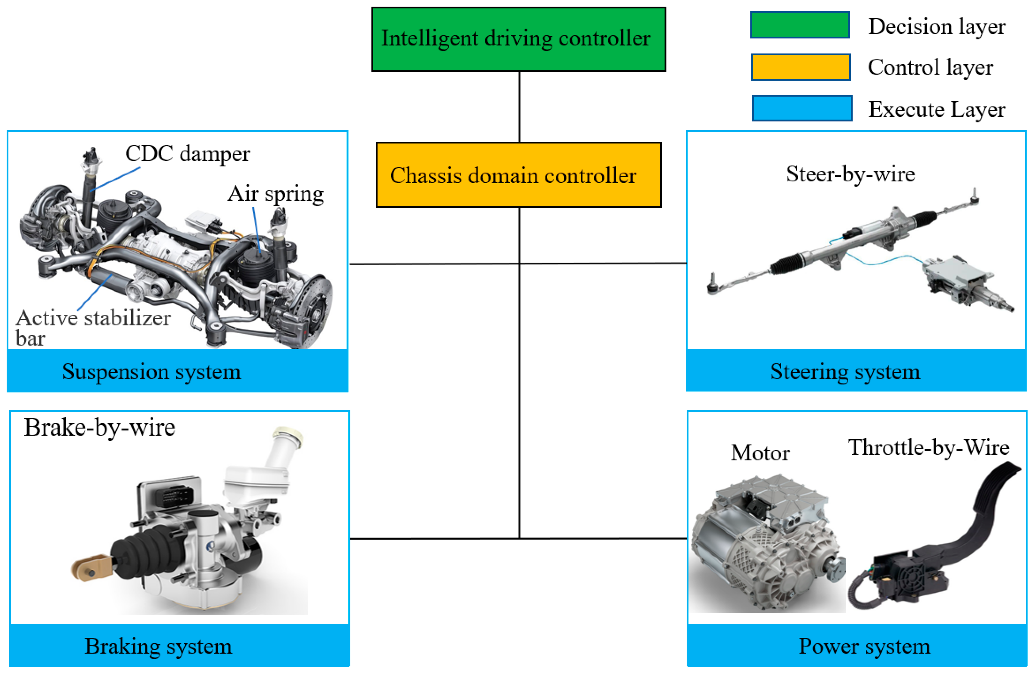
3. The Design of a Cooperative Control Strategy for HRBS Based on Chassis Domain Control

Chassis domain controller is the collective name of a whole system consisting of main control hardware, operating system, algorithm and application software, etc. It is a large computing platform, which can realize the integration of each chassis system controller and the separation of hardware and software so as to realize the centralized control of the vehicle’s steering, braking, suspension and power system, which is the “small brain” of the vehicle, and is a necessary building block to realize intelligent driving, and the structural block diagram is shown in Figure 5. Its main functions are as follows: (1) receive instructions from the upper sensing layer and decision layer; (2) establish a unified vehicle-dynamics model to achieve optimal cooperative control of multiple execution systems; (3) transmit upper-level decision commands to the four ECUs of the wire-controlled chassis subsystems to achieve motion control. The four wire-controlled chassis subsystems refer to the suspension, steering, brake and power systems, respectively; among them, the suspension system mainly realizes the control of the vehicle handling performance and ride comfort through air springs, CDC dampers and active stabilizer bars; the steering module mainly realizes the vehicle steering control through steer-by-wire (R-EPS,DP-EPS); the brake module, through brake-by-wire (EHB,EMB), achieves the vehicle’s braking and energy recovery; the power module through the line controls the throttle and motor to achieve vehicle torque control. At present, the energy recovery during braking is mainly achieved through the coordination of EHB and the motor; in order to improve the recovery efficiency of braking energy, this paper added the HRBS system into EHB to achieve efficient energy recovery during braking through chassis domain control.

3.1. Vehicle Anti-Loss Control Strategy

In order to solve the problem of the loss of vehicle control, the vehicle is controlled by ESP in traditional vehicles, in which ESP works as an independent system and does not require external input control commands. Since each system of the chassis works independently, it leads to a great difficulty in coordination and control between each system. In intelligent driving vehicles, because there are many control systems involved, in order to solve the coordination control problem between the systems in the vehicle, each execution system of the chassis has realized the separation of software and hardware; the control is unified and coordinated by the chassis domain controller, and each system only retains the hardware part and executes relevant actions based on the input of the chassis domain controller. In order to distinguish the ESP in the chassis domain from the traditional ESP, the ESP in the chassis domain that only retains the hardware part is called VACAS. For vehicle destabilization control, the chassis domain controller outputs control commands to the VACAS based on the detected wheel slip ratio, yaw rate and sideslip angle, and the VACAS controls the wheel-cylinder pressure based on the input commands.

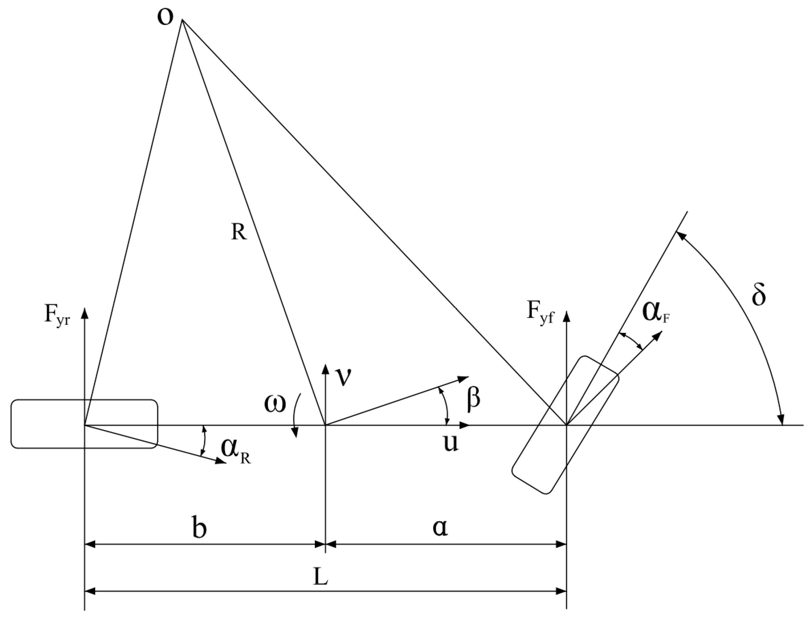
3.1.1. 2-DOF Vehicle Model

In this paper, the stability of the vehicle was judged based on the yaw rate and sideslip angle. In order to calculate the ideal yaw rate and sideslip angle, a 2-DOF vehicle model was established, see Figure 6, and we made the following simplification:
(1)
Ignore the influence of the steering system and directly take the front wheel angle as the input parameter.
(2)
Ignore the influence of suspension kinematic characteristics; it is assumed that the vehicle body only moves in a plane parallel to the ground, and we neglect the upward and downward motions along the z-axis, the pitching motion around the y-axis and the roll motion around the x-axis.
(3)
The forward speed of the vehicle is the constant.
(4)
The tire cornering characteristics are treated as linear characteristics.
(5)
Ignore the aerodynamic effects.
The differential equation of the 2-DOF vehicle model is given as follows [18,19,20]:
{ ( k f + k r ) β + 1 u ( a k f b k r ) ω k f δ = m ( v ˙ + u ω ) ( a k f b k r ) β + 1 u ( a 2 k f + b 2 k r ) ω a k f δ = I z ω ˙
where k f , k r are the cornering stiffness of the front and rear wheels, N/rad, respectively; β is the sideslip angle, deg; m is the vehicle mass, kg; u , v are the speed of vehicle along the X and Y axes, m/s, respectively; a , b are the distance from the front and rear axles to the vehicle’s center of mass, m; δ is the steer wheel angle, deg; ω is the yaw rate, deg/s; I z is the rotational moment of inertia of the vehicle around the Z-axis, kg∙m2.
The ideal value of yaw rate under the steady-state response can be obtained based on Equation (8):
ω r = u / L 1 + K u 2 δ
where K = m L 2 ( a k r b k f ) , L is the wheel base, m; generally, the lateral acceleration a y of vehicle is smaller than that of the lateral acceleration that calculated by the road adhesion coefficient μ , it is a y μ g ; otherwise, sideslip will occur. Since a y = u 2 / R = ( R ω ) u / R = ω u , R is the turning radius of the car, m. Therefore, it can reach the maximum yaw rate ω max , which is as follows:
ω max = μ g / u
Finally, the ideal yaw rate is as follows:
ω r = min { | μ g u | , | u / L 1 + K u 2 δ | }
By using a similar method, the ideal value of the sideslip angle is derived as follows:
β r = ω μ ( b u 2 + m a k r L )
In addition, the ideal sideslip angle is required to be less than the sideslip angle that is generated by its maximum yaw rate.
β r β max = ω max u ( b u 2 + m a k r L ) = μ g ( b u 2 + m a k r L )
Finally, the ideal sideslip angle is as follows:
β r = min { | ω μ ( b u 2 + m a K r L ) | , | μ g ( b u 2 + m a K r L ) | }

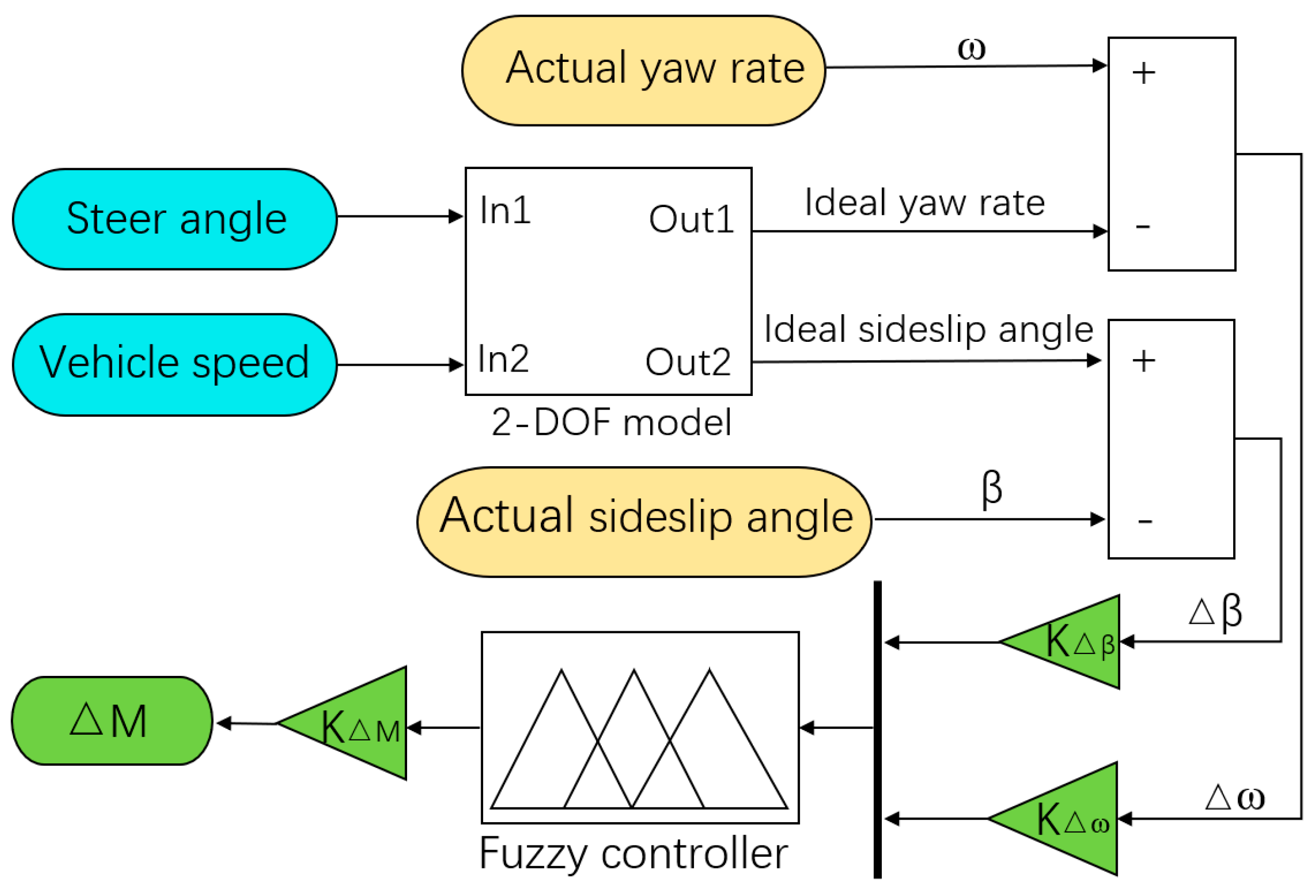
3.1.2. Calculation of Compensation Torque

The compensated yaw moment is generated by applying braking to the front and rear wheels of one side. Specifically, when the vehicle has a tendency toward oversteering, the braking of the outside wheels is controlled to generate the opposite yaw moment to compensate and prevent the vehicle from destabilizing. Conversely, when the vehicle has a tendency toward understeering, the braking of the inside wheel is controlled to generate the opposite yaw moment to compensate and prevent the vehicle from destabilizing, and the compensating torque is calculated as follows:
Δ M = F f B f 2 + F r B r 2
where F f , F r are the front- and rear-wheel braking forces, N; B f , B r are the front and rear wheel track, m, respectively. The braking force of the front and rear wheels can be allocated according to the ratio of the vertical load on the front and rear wheels, as follows:
{ F f = F f z F f z + F r z Δ M ( B f + B r ) / 4 F r = F r z F f z + F r z Δ M ( B f + B r ) / 4
{ F f z = b a + b m g F r z = a a + b m g
where, F f z , F r z are the vertical loads on the front and rear wheels, N, respectively.

3.1.3. Determination of Whether the Vehicle Is Out of Control

Whether VACAS is involved or not is determined according to the quasi-stable tolerance zone formula of yaw rate and quasi-stable tolerance zone formula of the sideslip angle, namely:
| Δ ω | | c ω r |
| C 1 β + C 2 β ˙ | 1
where Δ ω = ω d ω r is yaw rate deviation, deg/s; ω d is actual yaw rate, deg/s; c , C1 and C2 are constant. As long as the vehicle driving state does not meet either of the two inequalities in Equations (17) and (18), it means the vehicle is in a state of instability and needs VACAS intervention.

3.1.4. Vehicle Anti-Loss Control Strategy

The control logic diagram of the vehicle anti-loss control strategy in the chassis domain controller is shown in Figure 7, where the input variables of the fuzzy controller are the deviation Δ ω between the ideal value and the actual value of the yaw rate, and the deviation Δ β between the ideal value and the actual value of the sideslip angle are shown. The output variable is the yaw compensation torque Δ M . Input and output variables were set to five fuzzy levels named NB, NS, Z, PS, PB, representing the negative large, negative small, zero, positive small and positive large, respectively. Fuzzy rules are shown in Table 1.

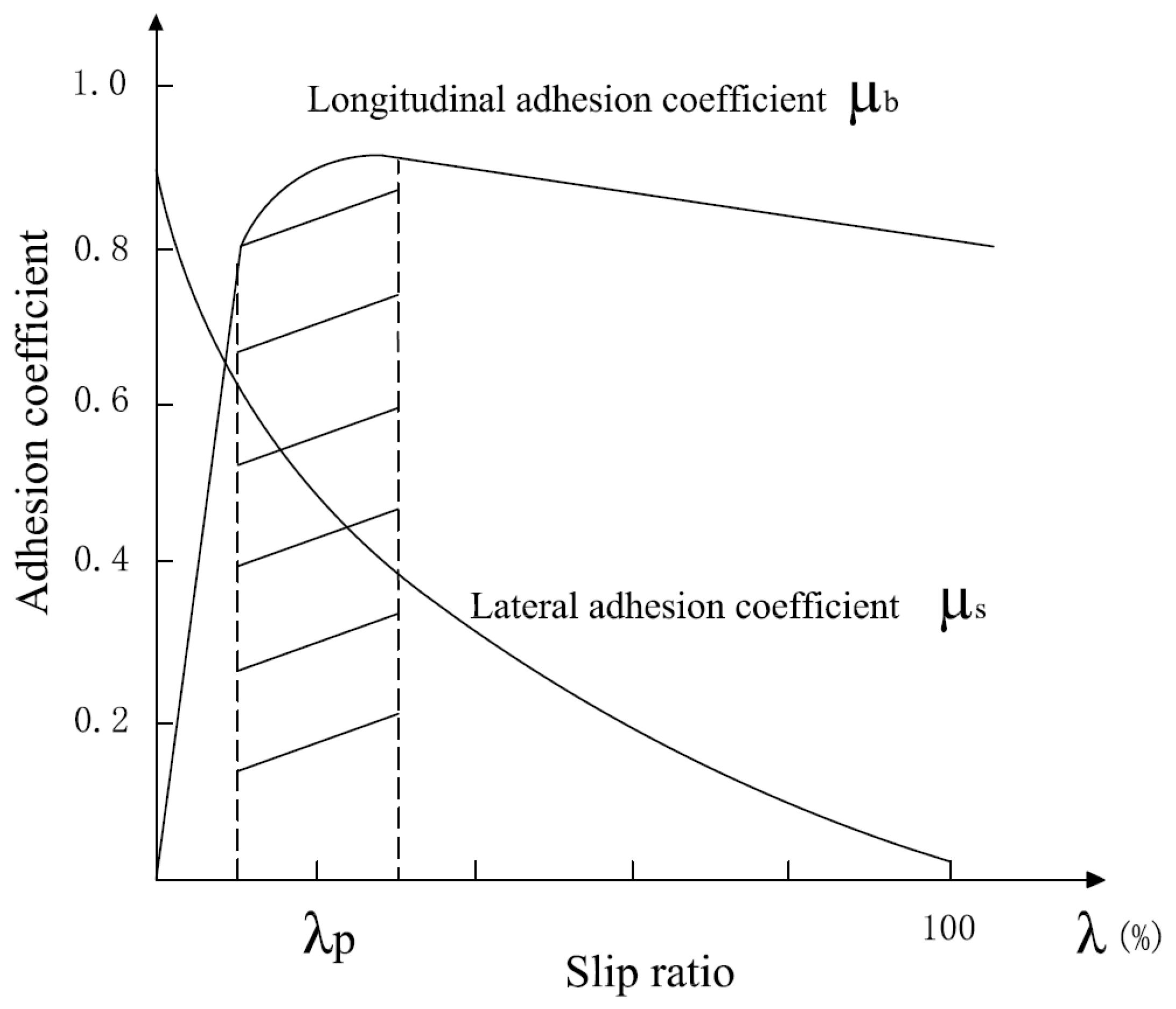
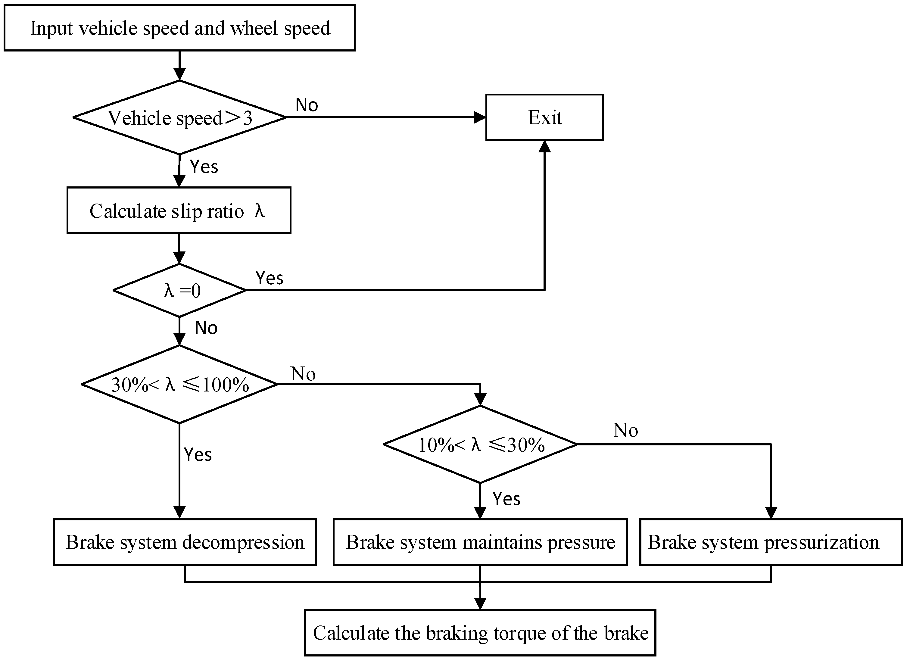
3.2. Wheel Anti-Lock Control Strategy

In traditional vehicles, ABS is an independent system to control the vehicle, without external input control command. In intelligent driving vehicles, the chassis domain controller outputs control commands to ABS based on the input vehicle speed and wheel speed, and the ABS hardware actuator controls the wheel cylinder pressure based on the input commands. Similarly, in order to distinguish traditional ABS and ABS in the chassis domain, the hardware part of ABS in the chassis domain is called WAAS.
If wheels are being locked in the process of braking, it is difficult for the driver to control the direction of the vehicle, leading to the loss of control. Figure 8 shows the relationship between road adhesion coefficient and wheel slip ratio. It can be seen that the longitudinal adhesion coefficient increases firstly and then gradually decreases with the change of wheel slip ratio. Moreover, lateral adhesion coefficient always decreases; the 10~30% of the shaded area is called the stable region, in which the ideal value of longitudinal and lateral adhesion coefficient are guaranteed, and the rest of areas can be called the unstable regions. Therefore, in order to prevent the vehicle from losing control when the wheel is locked during braking, the wheel slip ratio needs to be kept within the stable region [21,22].
Wheel slip ratio is defined as follows:
λ = u φ r u 100 %
where’ λ is the wheel slip ratio, %; φ is the wheel’s angular velocity, rad/s; r is the wheel’s rolling radius, m.
The following simplifications were made to model the wheel anti-lock control strategy in chassis domain controller:
(1)
Mechanical delay of the brake and other nonlinear factors are ignored, and the brake is simplified as an ideal model as well.
(2)
Nonlinear elasticity of the return spring in the solenoid valve, transmission delay of the brake pressure with the flow of the brake fluid, and action lag of other mechanical components are all ignored, and flow process of the brake fluid is characterized by the one solenoid valve link and the one integral link. The transfer function G ( s ) of the simplified model is expressed by
G ( s ) = k s ( T s + 1 )
Since the response of the solenoid valve in the process of switching on and off is rapid, the period to switch between the closed and open states is approximately 10 ms. Thus, the inertia link T in Equation (20) is 0.01, and the proportional factor k is 100.
In order to keep the wheel slip ratio in the stable region and thus obtain greater lateral and longitudinal ground adhesion, in this paper, the wheel anti-lock control strategy used a logical threshold value for control, and the wheel cylinder pressure was controlled by setting a suitable threshold value for the wheel slip ratio; when the vehicle speed is small or the wheel has no slip, the wheel anti-lock control strategy exits and does not work; when the vehicle speed or slip ratio does not meet the requirements, the wheel anti-lock control strategy starts to work, and its control logic diagram is shown in Figure 9. When the wheel slip ratio is 0~10%, WAAS start to pressurize the brake wheel cylinder and it will remain under pressure when the wheel slip ratio is 10~30%, and when the wheel slip ratio is greater than 30%, WAAS begins to decompress the brake wheel cylinder. The wheel cylinder pressure and the braking torque can be calculated by the following equation.
T μ = 2 f F μ R μ
F μ = p μ A
where T μ is the brake torque generated by the brake, N·m; f is the friction coefficient between the friction lining block and the brake disc; F μ is the single side of the friction lining block on the brake disc pressure, N; R μ is the effective radius of action of the friction lining block, m; p μ is the pipeline pressure, Pa; A is the effective action area of the friction lining block, m2.

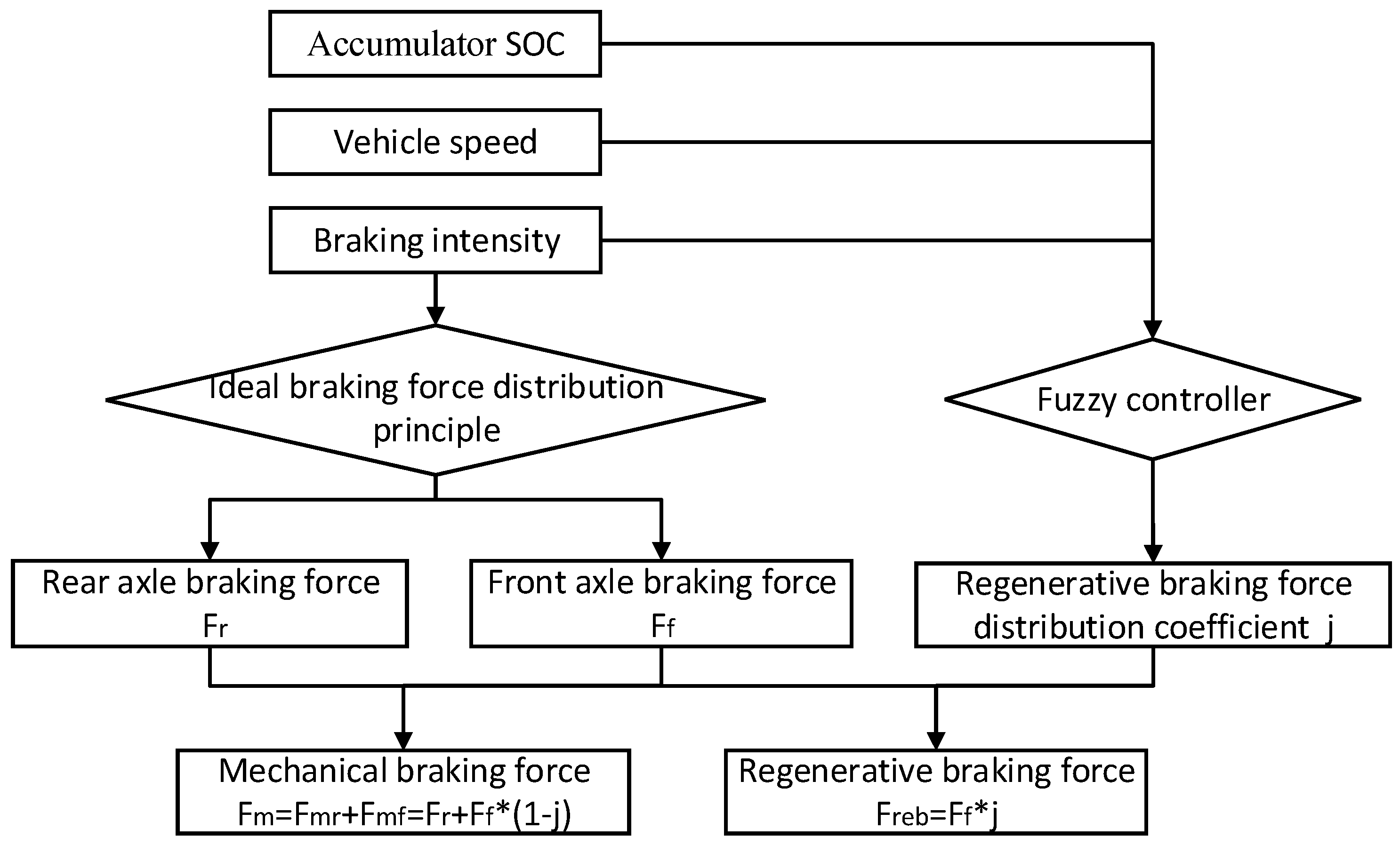
3.3. Regenerative Braking Force and Mechanical Braking Force Distribution

This paper studied a front-wheel drive vehicle, and the braking force distribution strategy is shown in Figure 10. When braking, the front and rear axles braking forces are first distributed according to the ideal braking force distribution principle [18], and then the calculation of the regenerative braking force distribution coefficient j is completed according to the fuzzy rules; finally, the distribution of regenerative braking force Freb and front and rear wheel mechanical braking force Fmf and Fmr is completed. Among them, the input variables of the fuzzy controller are the vehicle speed v , accumulator S O C , braking intensity z , and the output variable is the regenerative braking force distribution coefficient j . The control principles of the fuzzy controller are as follows:
(1)
When the vehicle speed is too high, less braking energy is recovered for braking safety; when the vehicle speed is too low, less energy can be recovered.
(2)
When the accumulator SOC is high, energy-recovery efficiency is low, as little as possible to recover braking energy; when the hydraulic accumulator SOC is low, energy-recovery efficiency is high, as much as possible to recover energy.
(3)
When the braking intensity is too high, the energy is not recovered for braking safety; when the braking intensity is low, the braking-energy recovery shall be increased [23].

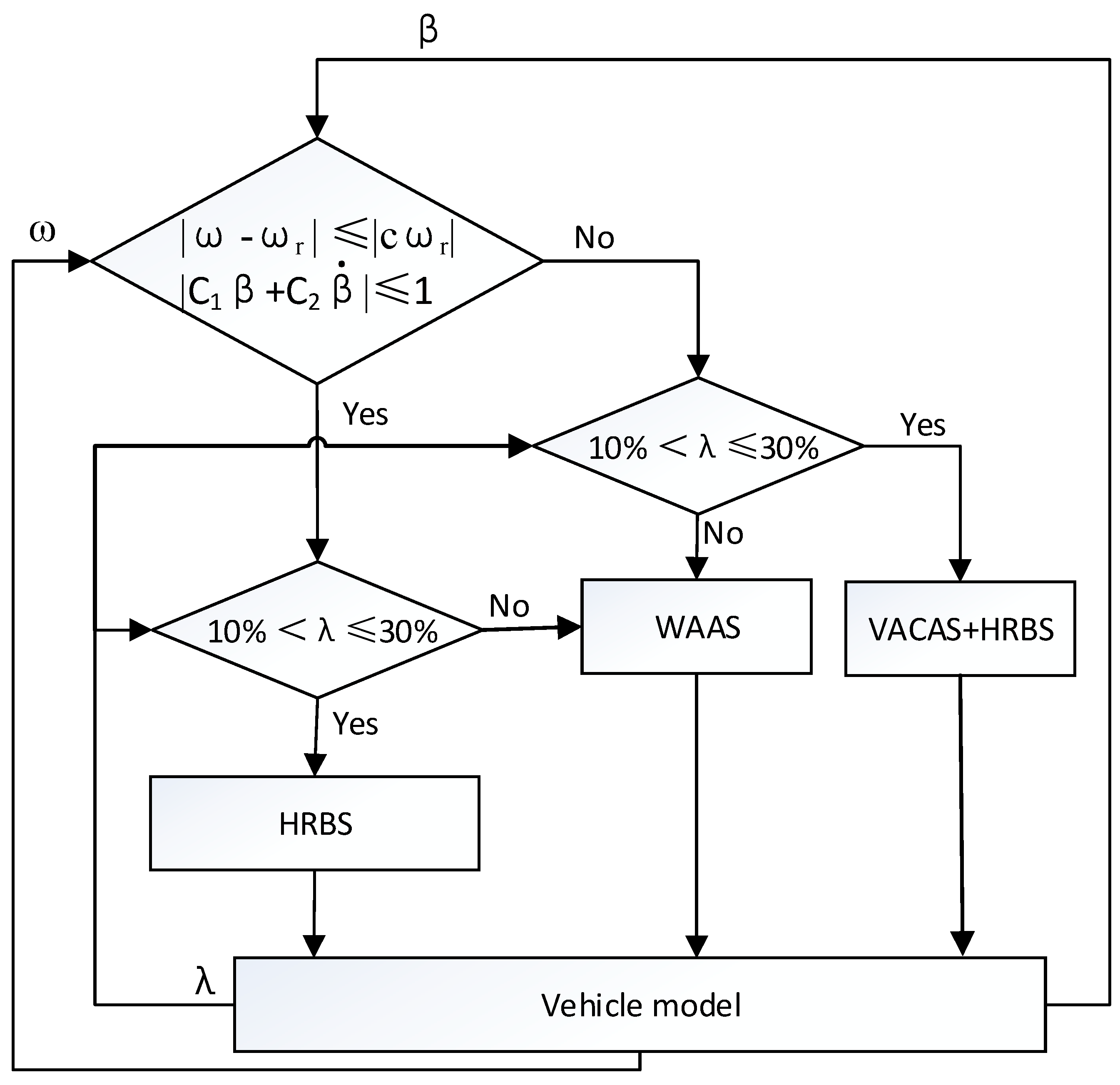
3.4. Design of the Cooperative Control Strategy for HRBS in Chassis Domain Control

In order to ensure that each system in the braking process of the intelligent driving vehicle is more adequate and better coordinated, a cooperative control strategy based on HRBS, WAAS and VACAS was built in chassis-domain controller, the control logic diagram of which is shown in Figure 11, as follows:
(1)
When both the yaw rate ω and the sideslip angle β meet the requirements of Equations (15) and (16), and the wheel slip ratio λ is within the stable region, VACAS and WAAS will not work; only HRBS will work.
(2)
When both the yaw rate ω and the sideslip angle β meet the requirements of Equations (15) and (16), but the wheel slip ratio λ is outsider the stable region, WAAS works, and VACAS and HRBS do not work.
(3)
When the yaw rate ω and the sideslip angle β do not meet the requirements of Equations (15) and (16), but the wheel slip ratio λ is in the stable region, VACAS and HRBS work, and WAAS does not work.
(4)
When the yaw rate ω and the sideslip angle β do not meet the requirements of Equations (15) and (16), and the wheel slip ratio λ is outside the stable region, WAAS works, VACAS and HRBS do not work. The requirement of the compensation yaw moment is fulfilled by WAAS controlling, and Δ M is required to return the car to attain to a stable state, because wheel slip ratio is not satisfied at this time. Thus, braking torque is not necessary to the wheels by means of the VACAS system. Otherwise, the wheel slip ratio continues to deteriorate. Hence, the braking force of the other wheels needs to be reduced by WAAS with Δ M to compensate the yaw moment.

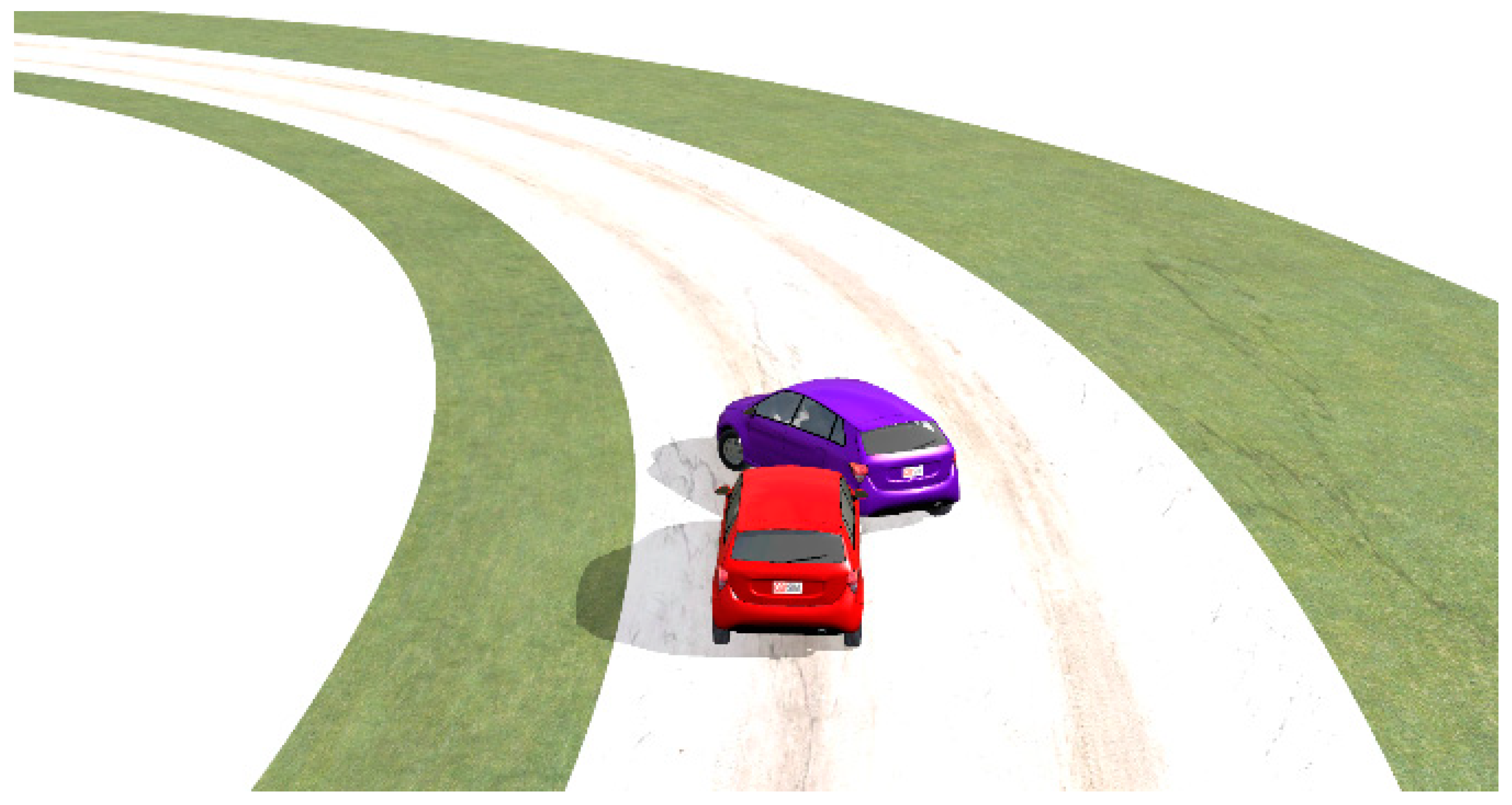
4. Simulation and Analysis

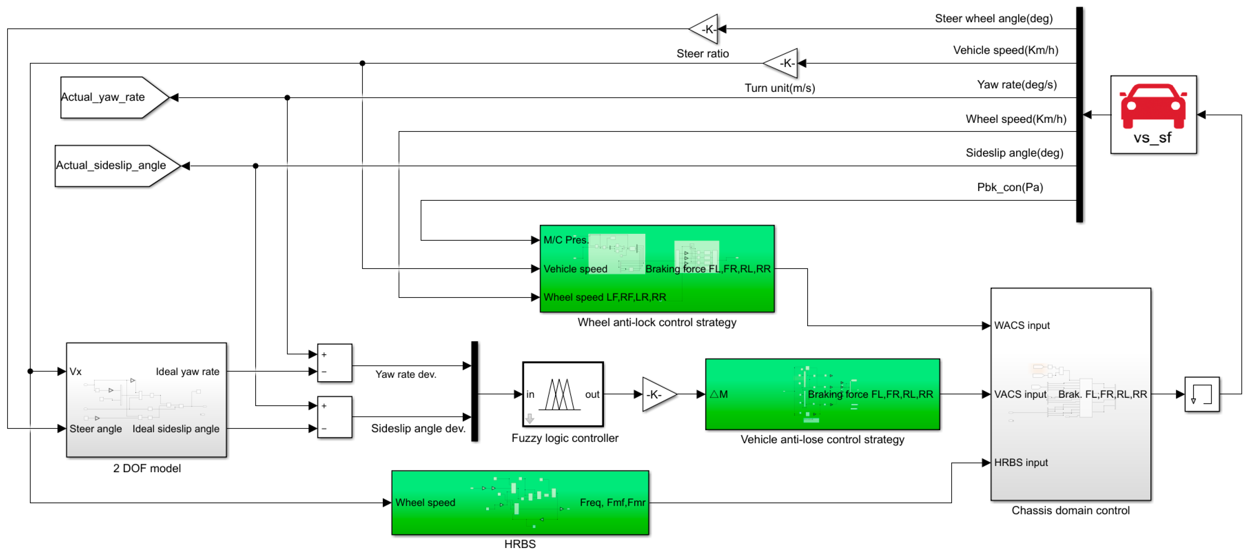
4.1. Build Vehicle Simulation Model Based on Chassis Domain Control

In order to verify the rationality of the established control strategy, the vehicle simulation model was built in Carsim software, the vehicle parameters are shown in Table 2, and the braking system simulation model of the chassis domain was built in Matlab software, see Figure 12. The vehicle model in Carsim software outputs the current steer wheel angle, vehicle speed, yaw rate, wheel speed, sideslip angle and wheel cylinder pressure to each module during the simulation process. The wheel anti-lock control strategy module calculates the wheel slip ratio according to the current input vehicle speed and wheel speed, and outputs the braking force to be applied to each wheel at the next moment to the chassis-domain control module according to the calculation results. The 2-DOF vehicle model in the vehicle anti-loss control strategy module calculates the ideal yaw rate according to the current input vehicle speed and steer angle, and transmits it to the fuzzy controller after making a difference with the actual yaw rate, and calculates the current compensating braking torque through the fuzzy controller. Finally, the vehicle anti-loss control strategy module calculates the required braking force for each wheel based on the compensation torque input from the fuzzy controller and feeds it to the chassis-domain control module. According to the current wheel speed, the HRBS module calculates the regenerative braking energy that can be recovered and the regenerative braking force that can be provided in the braking process, as well as the mechanical braking force that needs to be applied to the front and rear wheels and feeds it to the chassis-domain control module. Next, the chassis-domain control module calculates the final braking force that each wheel needs to be applied in the next time period according to the current input and according to the cooperative control strategy of Figure 11, which is input to the vehicle model in Carsim software.

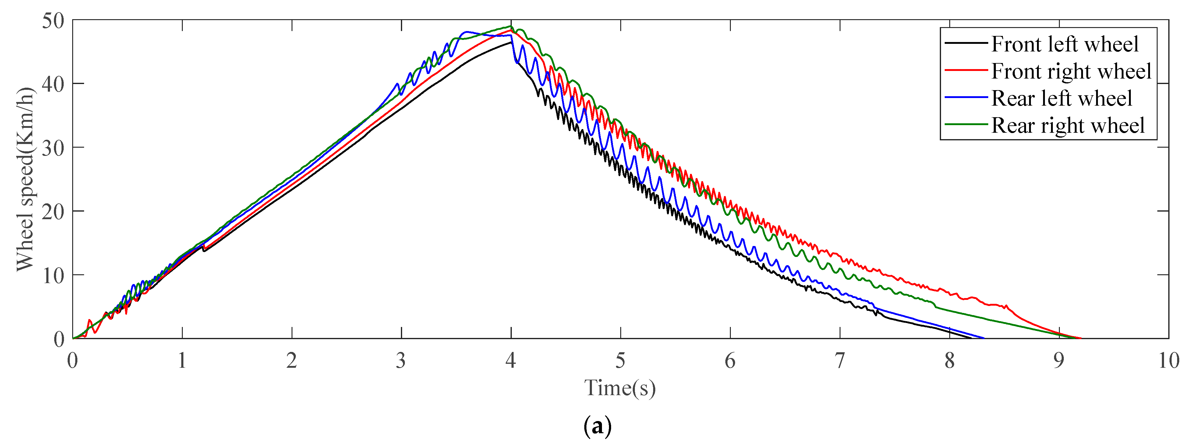
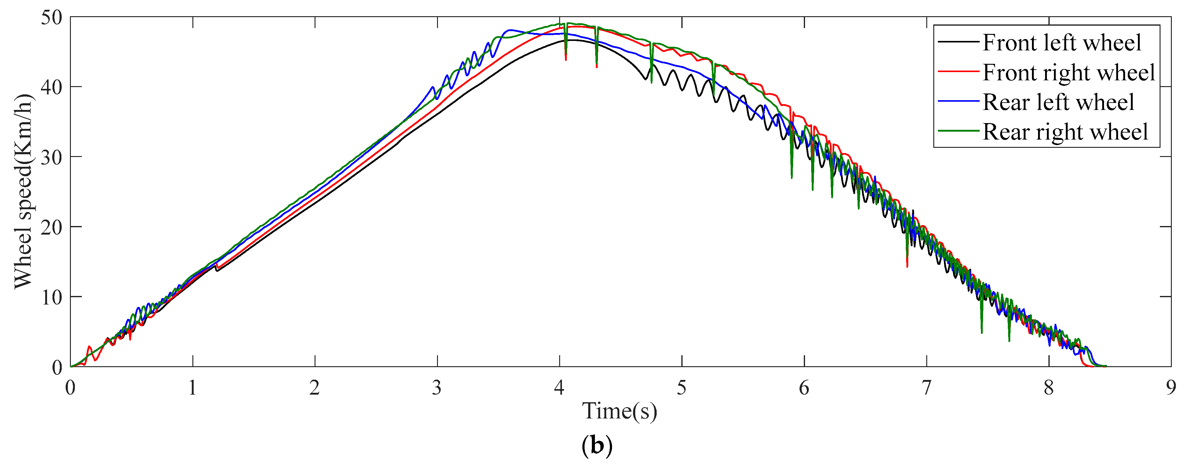
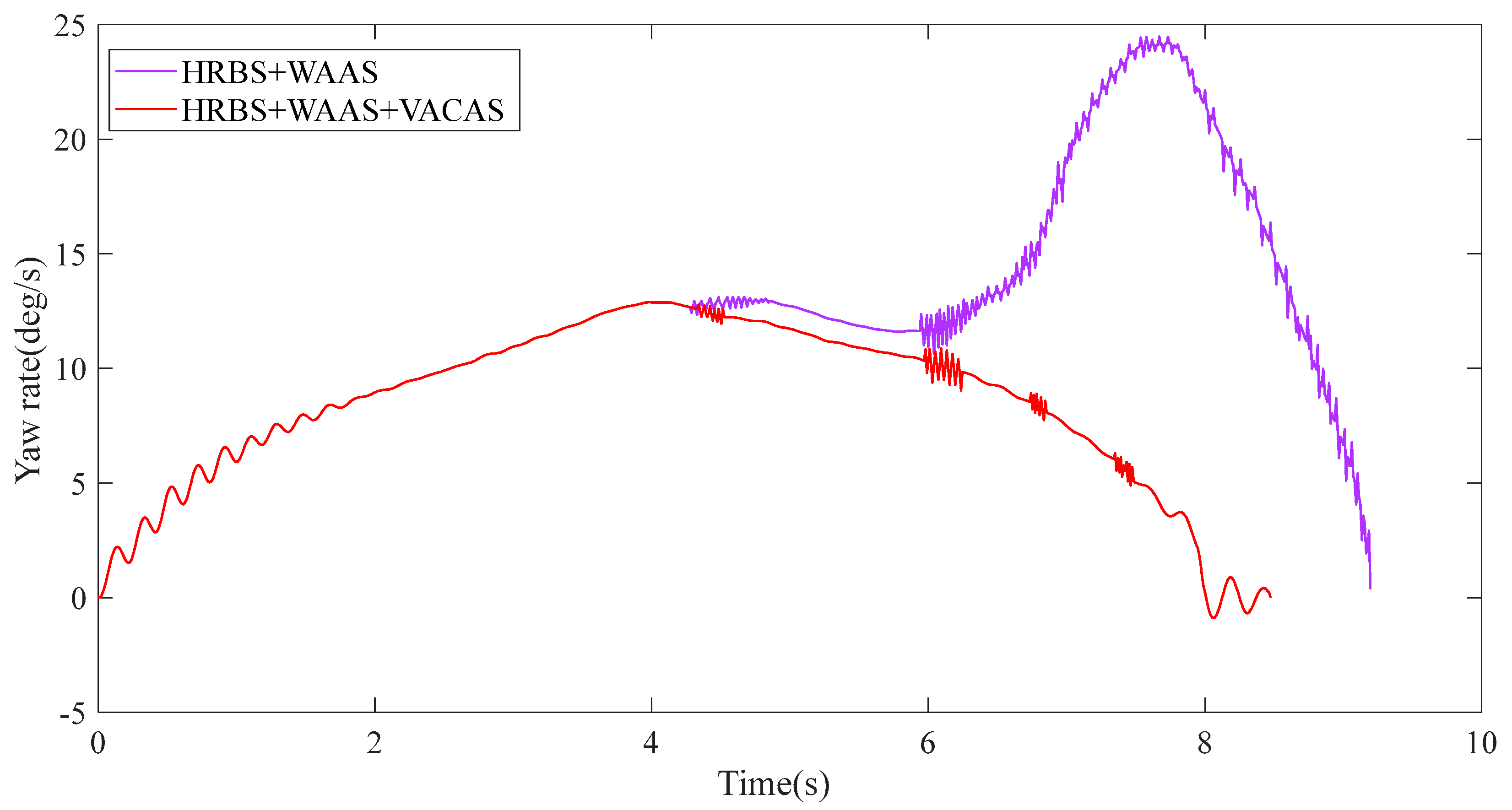
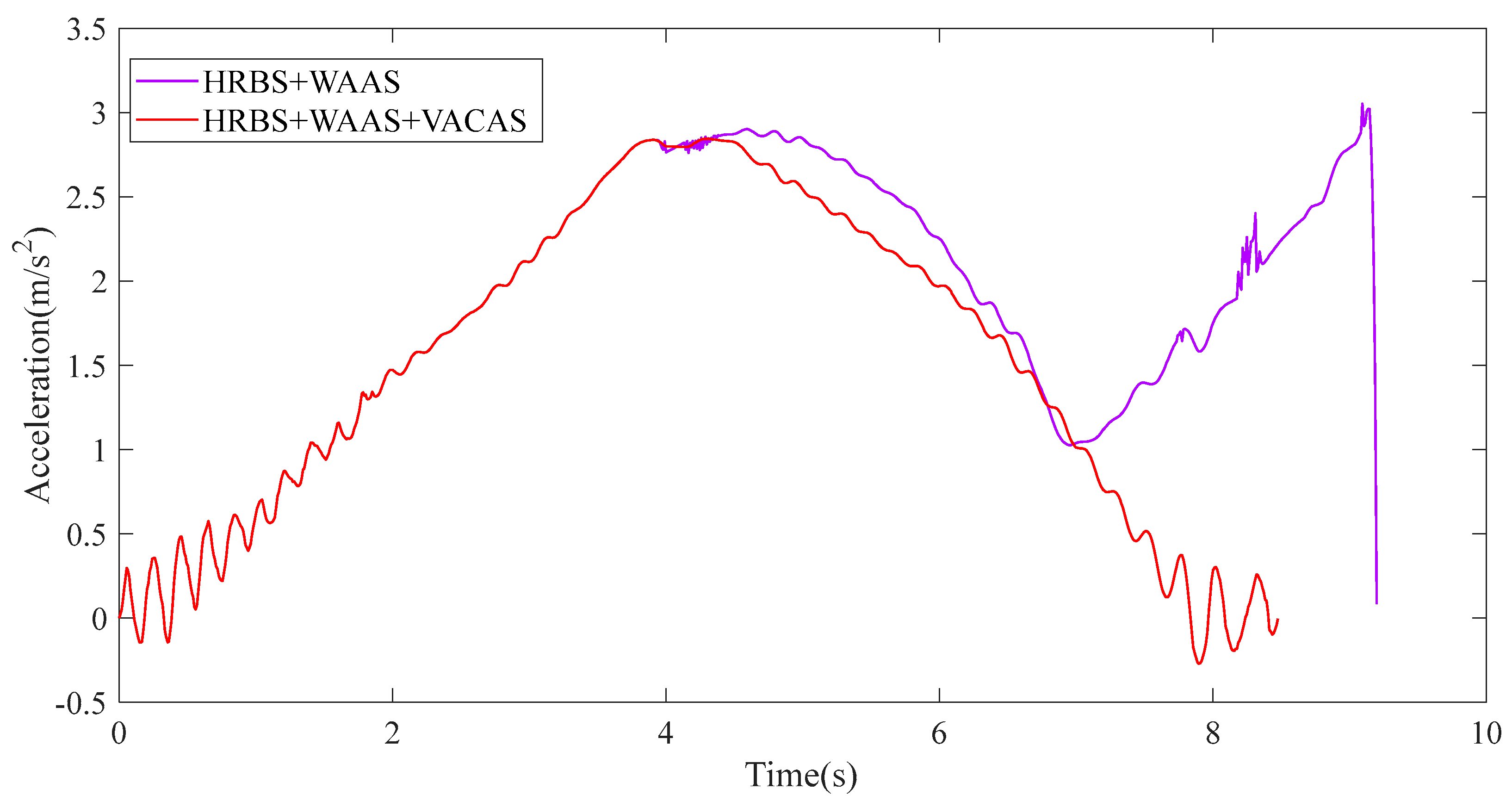
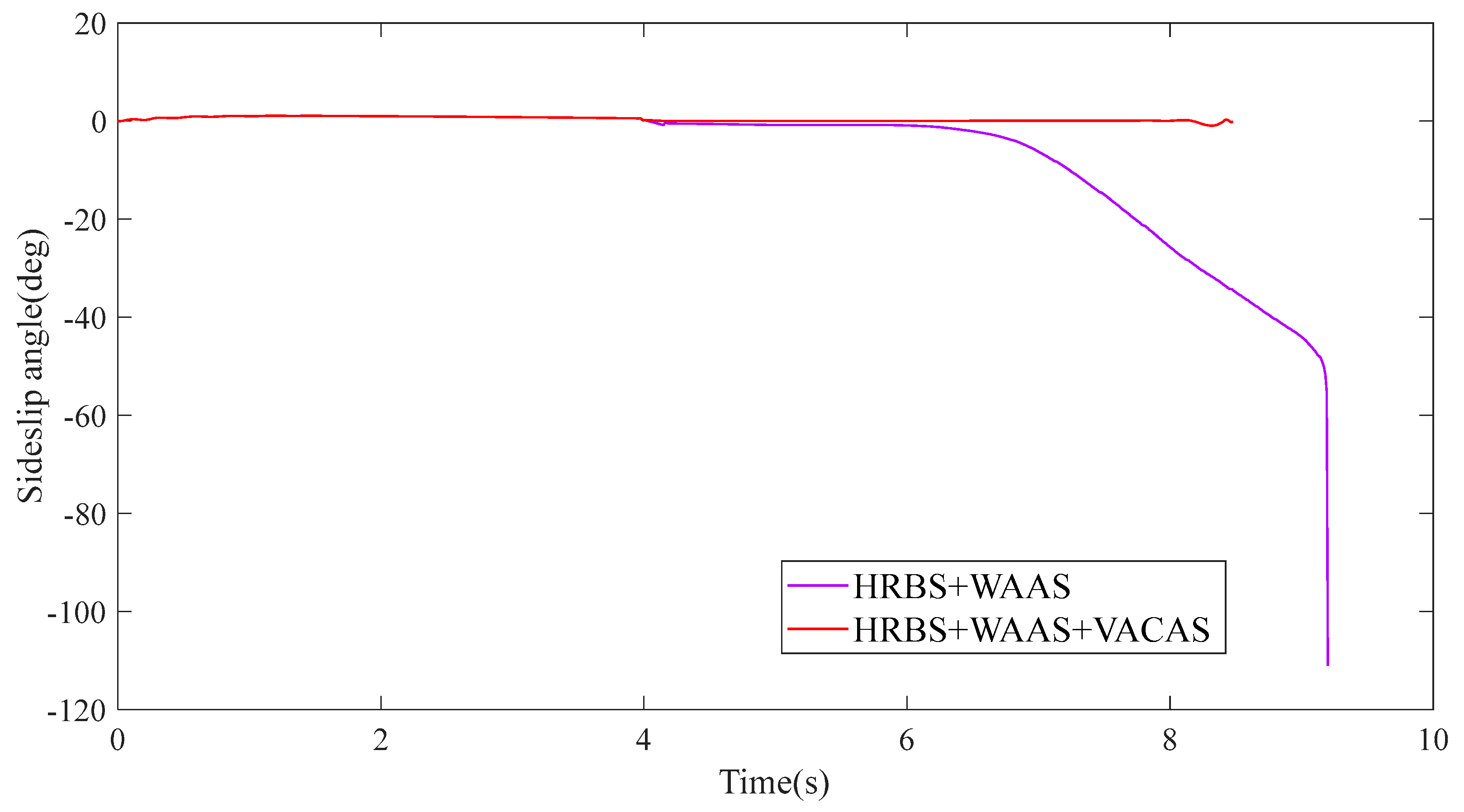
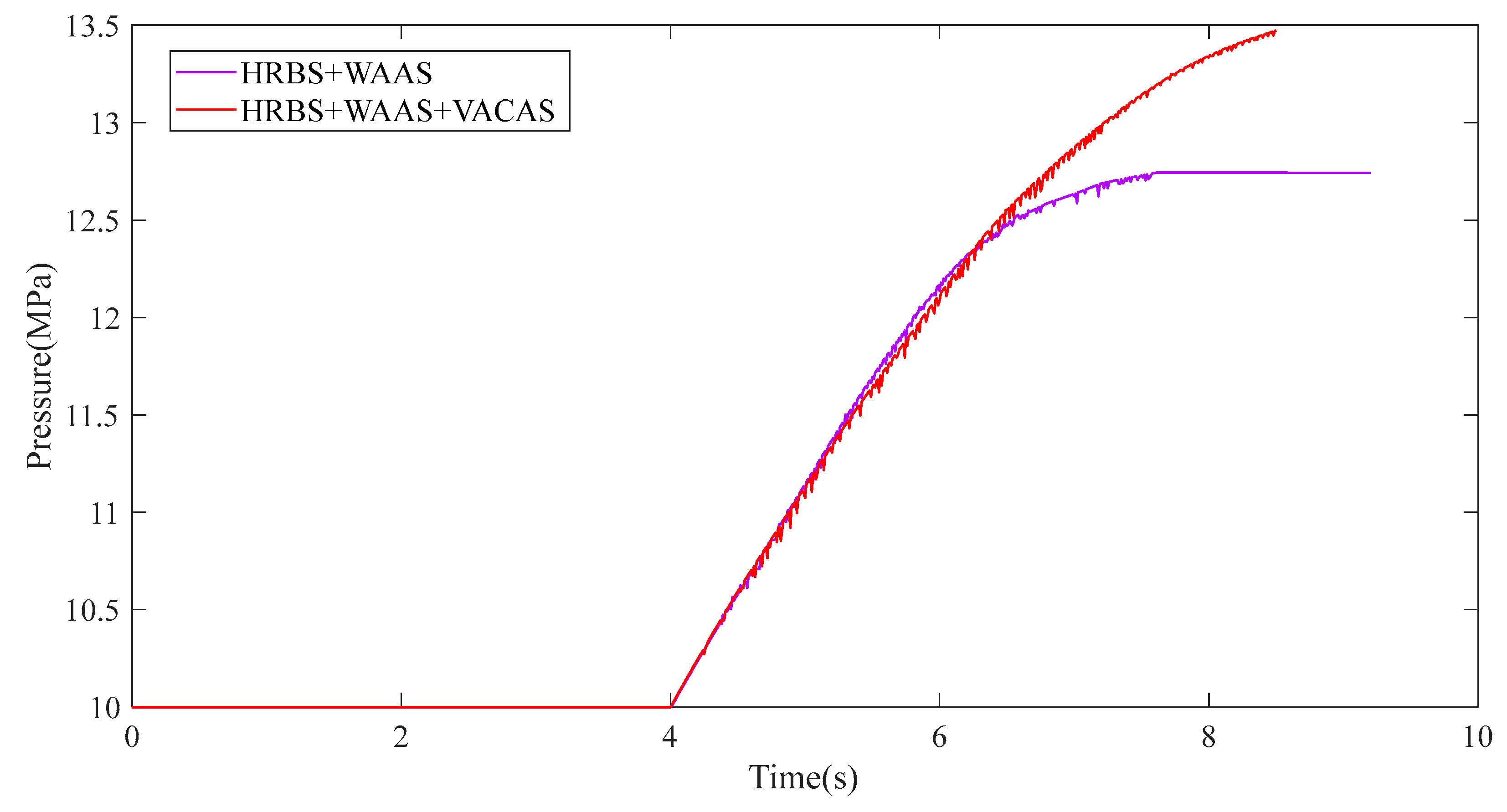
4.2. Simulation and Analysis

During the turning braking process, the load of left and right wheels will be transferred each other because of centrifugal force, because the braking forces required by the left and right wheels are different. If the braking force is not properly controlled, the wheels will lock and slip, resulting in loss of control due to understeering or oversteering. In order to verify the rationality of the designed control strategy, a cornering braking simulation was carried out on a bend with a radius of 40 m in Carsim software; the road surface is a low-adhesion coefficient road with an adhesion coefficient of 0.5. The vehicle started to accelerate around the circle first; when the speed reached 50 Km/h, the throttle was released and the braking force was slowly increased until the vehicles stopped, as shown in Figure 13; the red vehicle was equipped with WAAS, VACAS and HRBS, and the purple vehicle was only equipped with WAAS and HRBS.
Figure 14 shows the wheel speed change curve of the two vehicles in the turning braking process. It can be seen that, because the road adhesion coefficient is relatively low and the speed is relatively high, the VACAS of the vehicle equipped with WAAS, VACAS and HRBS intervened shortly after the braking started in 4 s, so the speed of the outside front and rear wheels fluctuated. The vehicle equipped with WAAS and HRBS did not have VACAS, so the rear wheels started to slip shortly after braking and WAAS intervened at the rear wheels.
Figure 15, Figure 16, Figure 17 and Figure 18 shows the change curves of yaw rate, acceleration, sideslip angle and accumulator pressure with time for the two vehicles during the simulation. Table 3 shows the comparison of the accumulator pressure during the turning braking process for the two vehicles; it can be seen that the change of yaw rate, acceleration and sideslip angle of the vehicle equipped with WAAS, VACAS and HRBS during the turning braking process was more stable, and the accumulator pressure increased by 26.64% compared with another vehicle equipped with WAAS and HRBS. Analyzing the reason, when there is a tendency to oversteer during corner braking, VACAS in vehicles equipped with WAAS, VACAS and HRBS intervenes in order to avoid the loss of vehicle control. However, the vehicle equipped with WAAS and HRBS, because there is no VACAS system, experiences loss of vehicle control in the sixth second. After the loss of vehicle control, the front wheel speed gradually decreased to zero and did not recover braking energy, so the accumulator pressure did not change after 7.5 s.
The simulation shows that the braking energy-recovery efficiency of the vehicle with the control strategy built in this paper was 26.64% higher than that of the vehicle equipped with WAAS and HRBS in the turning braking process, and there was no wheel lock and loss of vehicle control during the simulation. This shows that the cooperative control strategy of HRBS based on chassis-domain control designed in this paper can solve the problems of wheel lock and loss of vehicle control well under complex braking conditions.

5. Conclusions

In this paper, based on the fact that intelligent driving vehicles can realize coordinated control among various systems through a chassis-domain controller, a cooperative control strategy of HRBS based on chassis-domain control was built to coordinate WAAS, VACAS and HRBS to work by detecting wheel slip ratio, yaw rate and side slip angle to prevent wheel locking during braking, and when the vehicle has the tendency of understeering or oversteering, it can compensate by generating a yaw moment to prevent the vehicle from losing control.
A HRBS test bench was built, and the accuracy of the simulation model established in the paper was verified by bench tests. The designed cooperative control of the HRBS based on chassis domain control was verified through the co-simulation of Matlab and CARSIM software, and the results showed that the strategy can not only solve the problems of wheel locking and loss of vehicle control during braking, but also has a relatively high energy-recovery efficiency.
The control strategy designed in this paper only considers the braking system in the chassis domain, but does not consider the synergy with the suspension, steering and power systems in the chassis domain. For the future intelligent driving vehicle, the chassis domain should be considered as a whole, and how to design the HRBS to work together with other chassis systems will be the next research direction.

Author Contributions

Software, J.J.; Formal analysis, M.Y.; Data curation, F.S.; Writing—original draft, N.L.; Writing—review & editing, P.C.; Supervision, X.N. All authors have read and agreed to the published version of the manuscript.

Funding

This work is financially supported by the Natural Science Foundation of Zhejiang Province under Grant LQ20E050011, the Basic Public Welfare Research Program of Zhejiang Province under Grant LGG22E050019 and the Science and Technology Plan of Taizhou City under Grant 2003gy10.

Data Availability Statement

The data that support the findings of this study are available from the corresponding author, [Pengzhan Chen], upon reasonable request.

Conflicts of Interest

The authors declare no conflict of interest.

Abbreviations

List of abbreviation in dissertation.
AbbreviationExplanation
HRBSHydraulic Regenerative Braking System
WAASWheel Anti-lock Actuation System
VACASVehicle Anti-loss Control Actuation System
ABSAntilock Braking System
SOCState of Charge
ESPElectronic Stability Program
ECUElectronic Control Unit
CDCContinuous Damping Control
EHBElectro Hydraulic Braking
EMBElectro Mechanical Braking
R-EPSPinion- Electric Power Steering
DP-EPSDouble Pinion- Electric Power Steering
2-DOF2-Degree Of Freedom

References

  1. Gao, Y.; Chen, L.; Ehsani, M. Investigation of the effectiveness of regenerative braking for EV and HEV. SAE Trans. 1999, 108, 3184–3190. [Google Scholar]
  2. Han, J.F.; Tao, J.; Lu, H.J.; Xin, D.H. Status Quo and Prospect of Regenerative Braking Technology in Electric Cars. Automot. Eng. 2014, 36, 911–918. [Google Scholar]
  3. Sarmiento, M.A.D.; Valdés, L.A.D.P.; Ordoñez, Y.J.R.; Pinilla, C.B.; Dulce-Diaz, D.C. Modeling and simulation of a braking energy regeneration system in hydraulic hybrid vehicles in the Colombian topography. Period. Eng. Nat. Sci. 2021, 9, 755–766. [Google Scholar] [CrossRef]
  4. Li, N.; Wang, Q.C.; Li, J.L. Hydraulic regenerative braking system studies based on a nonlinear dynamic model of a full vehicle. J. Mech. Sci. Technol. 2017, 31, 2691–2699. [Google Scholar] [CrossRef]
  5. William, J.M.; David, C. Comparison of regenerative braking technologies for heavy goods vehicles in urban environments. Automob. Eng. 2012, 226, 957–970. [Google Scholar]
  6. Zhang, S.P. Analysis and Design of Series Hydraulic Hybrid Vehicle System. Coal Mine Mach. 2019, 40, 74–76. [Google Scholar]
  7. Wang, G.; Yang, K.; Ma, C.; Wang, J.; Wang, H.M.; Wang, J.L. Energy management control strategy of parallel hydraulic hybrid bus. Chin. Hydraul. Pneum. 2022, 46, 102–109. [Google Scholar]
  8. Xu, Q.W.; Zhou, C.; Huang, H.; Zhang, X.F. Research on the coordinated control of regenerative braking system and ABS in hybrid electric vehicle based on composite structure motor. Electronics 2021, 10, 223. [Google Scholar] [CrossRef]
  9. Savitski, D.; Ivanov, V.; Shyrokau, B.; Pütz, T.; De Smet, J.; Theunissen, J. Experimental investigations on continuous regenerative anti-lock braking system of full electric vehicle. Int. J. Automot. Technol. 2016, 17, 327–338. [Google Scholar] [CrossRef]
  10. Yao, Y.X.; Zhao, Y.N.; Yamazaki, M. Integrated Regenerative Braking System and Anti-Lock Braking System for Hybrid Electric Vehicles & Battery Electric Vehicles. SAE Int. J. Adv. Curr. Prac. Mobil. 2020, 2, 1592–1601. [Google Scholar]
  11. Kim, J.; Ko, S.; Lee, G.; Yeo, H.; Kim, P.; Kim, H. Development of Co-operative Control Algorithm for Parallel HEV with Electric Booster Brake during Regenerative Braking. In Proceedings of the IEEE Vehicle Power and Propulsion Conference, VPPC, Chicago, IL, USA, 6–9 September 2011; pp. 1–5. [Google Scholar]
  12. Krueger, E.; Kidston, K.; Busack, A. Reducing Disturbances Caused by Reductions in Regenerative Brake Torque; SAE Technical Paper No. 2011-01-0972; SAE International: Warrendale, PA, USA, 2011. [Google Scholar] [CrossRef]
  13. Le Solliec, G.; Chasse, A.; Geamanu, M. Regenerative braking optimization and wheel slip control for a vehicle with in-wheel motors. IFAC Proc. Vol. 2013, 46, 542–547. [Google Scholar] [CrossRef]
  14. Aksjonov, A.; Vodovozov, V.; Augsburg, K.; Petlenkov, E. Design of regenerative anti-lock braking system controller for 4 in-wheel motor drive electric vehicle with road surface estimation. Int. J. Automot. Technol. 2018, 19, 727–742. [Google Scholar] [CrossRef] [Green Version]
  15. Zheng, Y. Research on Efficient Braking Energy Recovery and Anti-Lock Braking Control of Electric Wheel Vehicle; Jilin University: Changchun, China, 2016. [Google Scholar]
  16. Mao, Y.Z.; Su, D.X.; Chen, M.X. Research on EV Regenerative Braking Cooperative ABS Control Strategy Based on Lock Prediction. SAE 2021, 75, 3316–3324. [Google Scholar]
  17. Chen, P.Z.; Pei, J.A.; Lu, W.Q.; Li, M.Z. A deep reinforcement learning based method for real-time path planning and dynamic obstacle avoidance. Neurocomputing 2022, 497, 64–75. [Google Scholar] [CrossRef]
  18. Yu, Z.S. Automobile Theory; Version 3; China Machine Press: Beijing, China, 2007. [Google Scholar]
  19. Andrei, A.; Klaus, A.; Valery, V. Design and Simulation of the Robust ABS and ESP Fuzzy Logic Controller on the Complex Braking Maneuvers. Appl. Sci. 2016, 6, 382. [Google Scholar] [CrossRef]
  20. Fan, X.; Wang, F.; Jin, K.; Xia, Q. Fuzzy logic control for vehicle stability control system with virtual prototype and experimental research. Int. J. Veh. Syst. Model. Test. 2016, 11, 1–9. [Google Scholar] [CrossRef]
  21. Li, J.Y.; Yang, L.J.; Yang, S.Y.; Liu, Y. ABS Control Strategy for Electric Vehicles Driven by Four Wheel Motors. Appl. Mech. Mater. 2013, 380, 512–515. [Google Scholar] [CrossRef]
  22. Xia, Y.S.; Wu, D.S.; Ping, L.L.; Xu, W.Y. Simulation research on braking of Tire Burst vehicle based on logic threshold. J. Yancheng Inst. Technol. (Nat. Sci. Ed.) 2021, 34, 11–16. [Google Scholar]
  23. Li, N.; Yang, J.R.; Jiang, J.P.; Hong, F.; Liu, Y.; Ning, X.B. Study on Speed Planning of Signalized Intersections with Autonomous Vehicles Considering Regenerative Braking. Processes 2022, 10, 1414. [Google Scholar] [CrossRef]
Figure 1. The working principle of HRBS.
Electronics 11 04212 g001
Figure 2. The HRBS test bench. 1—Motor, 2—Electromagnetic clutch No.1, 3—Magnetic powder brake, 4—Flywheel, 5—Revolution speed transducer, 6—Commutator, 7—Electromagnetic clutch No.2, 8—Hydraulic pump/motor, 9—Tank, 10—Relief valve, 11—Hydraulic pressure sensor, 12—Hydraulic accumulator, 13—Hub motor, 14—Proportional amplifier, 15—Oil discharge valve.
Electronics 11 04212 g002
Figure 3. The variation curve of accumulator pressure.
Electronics 11 04212 g003
Figure 4. The variation curve of flywheel rotational speed.
Electronics 11 04212 g004
Figure 5. Chassis domain structure schematic.
Electronics 11 04212 g005
Figure 6. The 2-DOF vehicle model.
Electronics 11 04212 g006
Figure 7. The vehicle anti-loss control strategy.
Electronics 11 04212 g007
Figure 8. The relationship between road adhesion coefficient and wheel slip ratio.
Electronics 11 04212 g008
Figure 9. Wheel anti-lock control strategy in the chassis-domain controller.
Electronics 11 04212 g009
Figure 10. Braking-force distribution strategy.
Electronics 11 04212 g010
Figure 11. Cooperative control strategy of HRBS based on chassis domain control.
Electronics 11 04212 g011
Figure 12. Whole vehicle simulation model based on the chassis domain.
Electronics 11 04212 g012
Figure 13. Cornering braking simulation.
Electronics 11 04212 g013
Figure 14. The variation curve of wheel speed. (a) Vehicles equipped with WAAS, VACAS and HRBS; (b) vehicles equipped with WAAS and HRBS.
Electronics 11 04212 g014aElectronics 11 04212 g014b
Figure 15. The variation curve of the yaw rate.
Electronics 11 04212 g015
Figure 16. The variation curve of acceleration.
Electronics 11 04212 g016
Figure 17. The variation curve of the sideslip angle.
Electronics 11 04212 g017
Figure 18. The variation curve of the accumulator pressure.
Electronics 11 04212 g018
Table 1. The fuzzy rules of vehicle anti-loss control strategy.
KΔβNBNSZPSPB
KΔω
NBNSNSNMNBNB
NSNSNSNSNMNB
ZPMPSZNSNM
PSPBPMPMPSPS
PBPBPBPMPSPS
Table 2. The parameters of the vehicle.
ComponentParameterQuantity
MassKg1700
Wheel basem2.8
Front wheel trackm1.55
Rear wheel trackm1.55
Height of center of massm0.53
Distance from center of mass to front axlem1.25
Distance from center of mass to rear axlem1.55
Air drag coefficient/0.28
Wheel rolling radiusm0.315
Table 3. Comparison of the accumulator pressure.
Accumulator Initial Pressure (MPa)Accumulator Final Pressure (MPa)Improved Efficiency(%)
HRBS + WAAS1012.74--
HRBS + WAAS + VACAS1013.4726.64%
Publisher’s Note: MDPI stays neutral with regard to jurisdictional claims in published maps and institutional affiliations.

