1. Introduction
Flash memory is a portable semiconductor device that is easy to use and non-volatile in nature. It consumes minimal power, has a high degree of shock absorption, and is significantly non-volatile. It provides data retention after it is unplugged from a power source. It uses random access. The device, during current research, has been implemented for usage along with various embedded system devices; for example, phones, tablets, computers, PDAs, and next generation sensor devices powered with sustainable and long-term energy solutions [
1,
2,
3,
4].
Flash memory mainly comprises two types of physical arrangements: blocks and pages. Blocks place the flash memory into erasable units, while every single page is further divided to consist of a fixed number of smaller pages (either 32 or 64). A page also happens to be a sub-unit of read and write. Parts of flash memory, in comparison with the components of other drives, lack the presence of movable parts, giving the ability to exhibit fast random read operations such as sequential read. Furthermore, owing to its lack of overwriting (in-place update) operations, it falls short in its ability to perform certain functions. It supports out-of-place updates. In order for an update to be implemented to a page, it should be erased before performing the update [
5]. For this purpose, a method referred to as ‘Garbage Collector’ is employed, in which pages are either labelled valid or invalid [
6].
When the read, write, as well as erase operations are compared in terms of access time, the read operation is fastest (80
s), while the erase operation is one of the slowest (2000
s) [
7]. The most critical problem in flash memory is the slow rate of erase operation, which degrades performance. Furthermore, each flash block has a finite number of erase cycles before it begins to cause errors. As a result, the number of erase counts in each flash block must be consistent and wear-levelling is an algorithm that mitigates this issue. The flash translation layer (FTL) was created to address these issues and drawbacks [
8]. Our proposed approach addresses these challenges more effectively as compared to other approaches.
To the best of our knowledge, the main novel contributions of our proposed RSLSP strategy are as follows:
The RSLSP leverage state-of-the-art shadow paging to avoid loss of data in the scenario of power outage for flash memory.
Our proposed RSLSP strategy protects structure corruption by making a copy of a table utilizing the mapping information from the table.
In the case of unexpected events regarding the system operations, it provides quick data retrieval with the advantages provided by shadow paging. Hence, the flash memory will be secure in spite of the fault during provisioning.
Last but not least, the proposed RSLP takes advantage of the BAST scheme in FTL environment making it compatible with the conventional file system. Hence, there will be no need for altering the conventional file system.
The rest of our paper is structured as follows:
Section 2 describes the literature review and research gap. In
Section 3, we discuss the works of related research. In
Section 4, we describe our proposed technique (RSLSP). In
Section 5, we present a comparison and discuss the experimental results. Lastly, the conclusion and future directions are given in
Section 6.
2. Literature Review
A notable power off recovery system called PORCE for flash memory has been created by researchers in the field. This scheme has been implemented to be familiar with flash memory. The plan’s objective is to make the framework security without the need of being extremely proficient. Additionally, attempts are being made to increase the limit and efficiency of flash memory by utilizing this plan [
9]. To be prepared for a sudden loss of power, the suggested technique, the storage mapping of the table was distributed in a spare region of the page. In this strategy, FTL map is placed in a storage table instead of causing past PLR innovation. Flash write codes are then added to it. The same method is used in uncommon cases after an incidence of power loss. It is usually more viable to plan storage methods as quickly as possible. The researchers then analyze and monitor the outcome before declaring that the proposed strategy is larger than the transfer of technology. They then write the performance of the flash. Furthermore, the proposed strategies, A-PLR and S-PLR, give an additional benefit: they lessen administration for map block and dispose of freezing Overhead [
10].
Motivenga suggested the Fault-Tolerant Recovery Mechanism (FTRM), an efficient fault-tolerant crash recovery scheme paired with an effective separation algorithm, i.e., the hot/cold page. FTRM is based on managing inconsistencies in RAM file mappings and flash memory effectively in FTL page mapping for rapid recovery from crash. However, we provide a system for crash recovery that is suitable for a hybrid FTL mapping of FAST addresses. Our recovery system is built on the logging of checkpoints as the key distinction between the two recovery systems [
11].
Similarly, Choi [
12] suggested a general FTL structure with the Hierarchically Interacting Protocols crash recovery module (HIL). HIL handles accident recovery by two stages of data base borrowing: structural restoration and functional rehabilitation. However, our crash recovery strategy is designed for hybrid FTL mapping and provides solution to crash recovery in two stages: recovery and constancy control.
2.1. Flash Translation Layer (FTL)
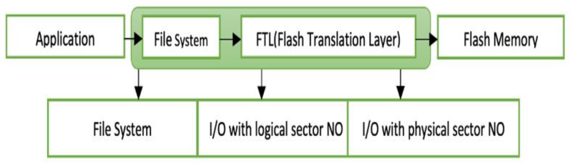
The software architecture is demonstrated in
Figure 1.
Figure 1 shows the Application, file system, FTL, and flash memory is the logical flow as written by in code. The concept revolves around the FTL layer.
FTL uses the technique of disk-like updates that takes place in-place with a Logical Page Number (LPN)-dependent data page. Hence, the effective FTL strategy has a significant effect upon the overall performance for flash memory because it is directly proportional to the in-place (update) performance, with balancing a wearing for every data block [
2,
4].
2.1.1. FTL Characteristics
The key characteristics of flash memory that are the basis of many research topics are discussed in this section.
2.1.2. Characteristics of FTL Algorithms
The logical-to-physical address map holds the responsibility of converting logical addresses in the file system as well as a physical address in the flash memory [
3]. In the second algorithm involves recovery of data after a loss of power.
2.1.3. Characteristics of Flash Memory Operations
Asymmetric processing speed: Read and write operations in flash memory are asymmetric. Erase operations are considered to be substantially slower than read/write operations because they are performed at a coarser granularity of a block [
13]. Furthermore, there is an asymmetry in the access times of reads and writes. Furthermore, write latency occurring in erase is usually higher than read latency (by a factor of 4–5). The primary explanation for this is that writing takes longer than reading because draining electrons from a flash cell takes longer. Out-of-place upgrades are the most cost-efficient in flash memory. This is due to the fact that erase operations take place at the block granularity level, whereas writes take place page to page. When the host issues an upgrade, an out-of-place update invalidates the existing edition of the page. The modified new version is then written to a clean flash file, after which the mapping table is modified. Mapping tables must be revised on a daily basis. These adjustments are tracked by FTL. Garbage Collection: The out-of-place upgrade characteristics of flash memory result in a significant number of invalid pages. Pages that contain out-of-date material that should be deleted are known as null pages. By erasing the blocks that hold these null pages, garbage disposal reclaims them. To delete a lock, all pages in the block must contain invalid data.
3. Background and Motivation
This section describes different address mapping techniques, merge operations and memory operations.
3.1. Address Mapping Schemes
Address mapping is very important in FTL algorithms. The performance of the allocator has a significant effect on the overall performance of the FTL algorithm, and hence the flash memory. As a result, the implementation of address mapping strategies must be performed with caution in accordance with the task at hand. In addition, an output affecting operation known as the merge operation is thoroughly addressed [
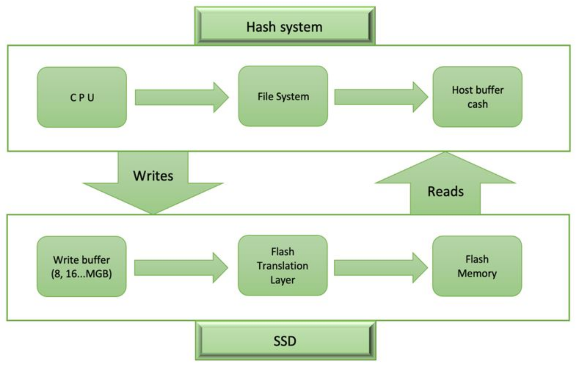
14]. Since addresses from an outside environment, such as the file system, are given in logical address form, address mapping is required in flash memory. This ensures that any device outside of the flash memory cannot see the flash memory’s physical address. As a consequence, address conversion from logical to physical address of flash memory cells is necessary. After a flash FTL receives a logical address from the host device, it consults the address mapping table to find the corresponding physical address. The process, read/write/erase, is then carried out as required as shown in
Figure 2.
As mentioned earlier, overwrite operations are not feasible for flash memory, as previously mentioned. Upgrades are instead performed by loading new data into a blank flash page and validating the existing one. Since address modifications for update information must be registered, address mapping is also done here. FTL redirects the physical address to a clean location when the host requests an update operation. This is because when a write request is made, flash memory tends to avoid overwrite operations. In addition, the merge process, which has an effect on performance, is thoroughly discussed. Page Level Mapping: This sort of mapping is performed on a page-by-page basis. The logical page is allocated to physical page. Since it is a one-to-one conversion, it does not necessitate costly full merge operations. Nevertheless, it has a good performance results for both read and write operations, it uses a lot of SRAM memory to store the mapping information [
10,
15]. There is a cap on the volume of SRAM that can be utilized. The mapping table takes up about 4 GB memory when utilizing a page level mapping for 1 TB flash memory, for instance (assuming the 2KG page having 8 bytes/mapping entry).
DFTL (Demand-Based Page Level FTL), a newly proposed FTL scheme, attempts to address this weakness of page level mapping schemes through storing of the mapping data table in a flash memory rather than SRAM. This scheme addresses the problem of high SRAM consumption caused by mapping at the page level, but it introduces a lookup overhead for flash memory. This is especially noticeable in operations that require a considerable amount of writing. Similarly, besides this overhead, it achieves strong read efficiency, but falls short of pure page mapping performance. Furthermore, DFTL disregards spatial localization. In certain instances, spatial positioning is a crucial concern for an effective processing of data [
15]. Another solution [
10] was introduced to reduce the address mapping table’s memory usage. Instead of flash memory, this prototype proposed caching address mapping information on the host DRAM. It uses two-level address mapping, similar to DFTL. As a result, it suffers from the same extra overhead problem as DFTL. They devised a host-based hinting method that caches mapping information upon a host DRAM to reduce the extra lookup overhead. If a hint is sent to SSD (i.e., the information on address mapping) by the host prior to the current read/write request, it uses hint mapping in place of reading the flash mapping that will save a read latency.
Sudden Power-Off Recovery (SPOR) [
4] was suggested to be an effective recovery scheme for FTL page mapping (e.g., DFTL) [
16,
17]. It retains three types of cache, i.e., a root page, L2/L3 mapping and description pages, so that the on-RAM and on-NAND data are synchronised rapidly and effectively, and quickly recover crashes. However our crash recovery scheme is optimised to Quick, one of the hybrid mapping FTLs, differently from SPOR, based on a DFTL, that is one of FTL’s page mapping.
Block level mapping: the logical page address in this system is divided into two—a block and an offset. The quotient refers to physical address regarding the block and the remainder consists of a page address for the block by splitting the physical page address with the number of pages in a physical flash block (also known as the offset). This approach has been mapped (several logical addresses mapped with one physical block). This increases the overall memory use of page mapping. This kind of strategy has its own downside though, i.e., when host problems occur from an overwriting procedure (update) on one page, the valid flash blocks pages must be transferred to clean blocks (physical), i.e., before a physical block can be deleted, the valid pages and the modified page of the original data block can be copied into a novel clean type of physical block. The deleting process is later followed by waste disposal. However, many block level mapping erases occur leading to extra expense and flash memory overtime depletion.
Hybrid Mapping: Various hybrid schemes were proposed [
9,
12,
18] to solve the limitations of page and block level mappings. The log buffer solution is often implemented by these algorithms.
The Bast Scheme Overview
This paragraph reviews the BAST scheme briefly. The file system sees the flash drive as a series of logical sectors, i.e., a block unit equivalent to a hard disc. Therefore, the FTL write interface is set to: Writing (lsn, industry), which means writing the logical sector number lsn to the position of the ‘a given sector’ [
19]. When the FTL receives a file system written order, it will find a physical position in the flash memory of a field to write: first it will determine the logical (short, lbn) block number with the specified lsn and then obtain the physical number (shortly, pbn) of the block mapping table for lbn. Next, the four offset measurement in the physical block found to write sector data. Finally, the sector writes in the data block at the offset identified (which is another representation of the physical block).
If one of the previous write operations was already used in the specified offset in the data block, the FTL will enter the specified field in a free block from the free block list at the same offset. The FTL will use the same offset. First, the data block copies of all written sectors except the sector on the offset identified. Finally, the FTL deletes and returns the data block to the free block list. In case of a conflict between the current text and the previous texts, a great deal of copying and deletion of the sector is required. The merge procedure is referred to as a set of such operations. Many FTL techniques were supplied in order to solve this issue of BAST scheme. De facto, the best FTL technique to solve this issue [
20].
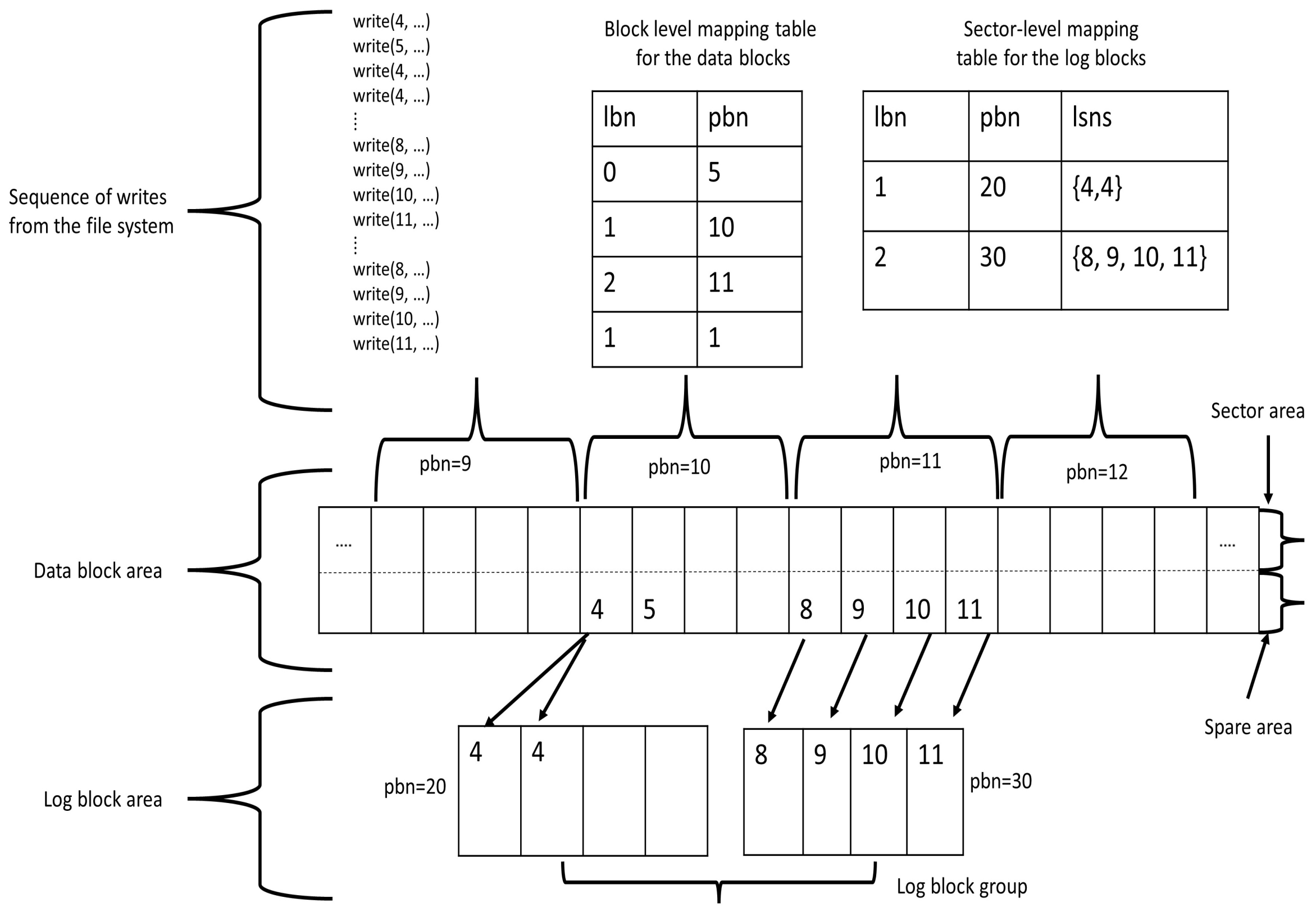
The BAST scheme records data in temporary storage, including log blocks that thus decreases the number of merge operations, as collisions occur. We illustrate in detail the BAST scheme by an illustration below. The pictorial overview is denoted in
Figure 3.
Figure 3 shows the sequence of writes released from the file system in the top-left section, while the top-centre and the top-right section display the block level and the page level mapping tabs which are normally held on the flash scene in the SRAM region. The BAST algorithm obtains a data block 10 from an address mapping table of the block utilizing a logical block 1, i.e., (=4 div 4) if the first kind operation is named in the figure. Then a given sector is stored in the data block ten in Offset 0 (=4 mod 4). The second write operation is carried out in the same way as the first write operation. Since a collision happens in data block 10 during the third write process, the sector is to be written to the Ist offset into the log block (i.e., with pbn = 20) that is allotted to the number 1 logical block from the list of the log block. The sector is led to the next empty offset in the current log block in the case of the fourth write operation. The remaining writes would be used to construct the 2nd log block (i.e., having a pbn = 30). Moreover, the sector-level mapping table is shown with a pictorial overview in
Figure 3.
Other data blocks [
21], such as the data block 12 as indicated in
Figure 3. Since there are no more log blocks to assign, the BAST scheme picks, erases, and returns one of the used log blocks in this scenario. It must execute a merge operation in the initial data block and copy it before returning the victim log block. To put it another way, the up-to-date sectors in the two blocks are copied to a free block, which is then swapped with the data block. Around the same time, the block-level address mapping table must be modified, and the entry in the sector-level address mapping table corresponding to the victim log block must be deleted. One curious aspect is that the merge process can be optimised based on the state of the victim log block. For example,
Figure 3 shows all the sectors consisting in pbn = 30 log block are sequentially written. In addition, they are equal to block power. In such a scenario, no copy is required to a free block; instead, a victim log block must be shared with a data block. The turn operation is the name given to this operation.
3.2. Merge Operations
The delete-before-write features of flash memory result in many invalid pages in a block, which causes the garbage collection algorithm to perform many erase operations. The garbage collection scheme begins merge operations to gather correct pages of blocks before erasing. As a result, the merge operation has a significant impact on FTL efficiency, as it causes several copy and erase operations before erasing. As a result, one of the key problems in the architecture of FTL schemes is reducing the number of merge operations. Switch, selective, and absolute merge are the three types of merge operations. Switch merge is the cheapest of the three merge operations since it only requires one delete operation per block. If all pages in a block are changed in the same order, this is known as a switch merge. The old block is then submitted to the garbage collection system until all pages have been modified in a linear fashion and all pages of the old block have been invalidated. An FTL switches the log block into the data block, erasing the data block loaded with invalid pages. Furthermore, the mapping table is revised to reflect the fact that the updated block is now the valid block.
A partial merge is equivalent to a swap merge, in that the number of valid page copies is increased. This happens when the pages of a block are not changed in the order they were created. The block’s correct pages are copied to clean blocks, and the null block is later erased. This process would incur additional costs as a result of the additional page copies. The most expensive of the three is a complete integration. As a consequence, it has the maximum overhead since it initiates further copies and erases. Valid pages are copied to the clean block from the data and/or log blocks. It (the clean block) becomes the data block after all of the correct data has been copied to it. As a result, a single complete merge causes a slew of read, write, and update operations.
3.3. Memory Reoptimized
The memory criteria for the comparable calculation on the other hand while also archiving the mapping results. It should be mapped to animation contained in permanent storage, allowing for greater RAM use. It is capable of producing results. A variation of sector FTL blocks is used in some algorithms. However, each FTL algorithm is believed to be used in a full flash in this paper. The memory system will be examined in the following section. They presume (a flash memory size of 128 megabytes and 8192 blocks) in addition to the 8 gigabytes (524,288) blocks. Furthermore, each block is made up of 32 sectors—3 bytes in the sector mapping 128 megabytes, and 8 classes to represent all of the sector numbers in all bytes.
In block mapping, two-byte Bay memory is used, while flash memory is ucopy-and-eraseck mapping. In total, 128 megabytes is needed to represent the total number of bytes in all of the flash memory blocks (8 groups of three bytes, byte flash memory). You will need hybrid maps. In a block of flash memory, a double-byte sector byte block maps 128 megabytes. In the flash memory, there is an 8-gigabyte community of 1 byte regarding sector mapping with three bytes for block mapping [
2].
3.4. Map Block Method
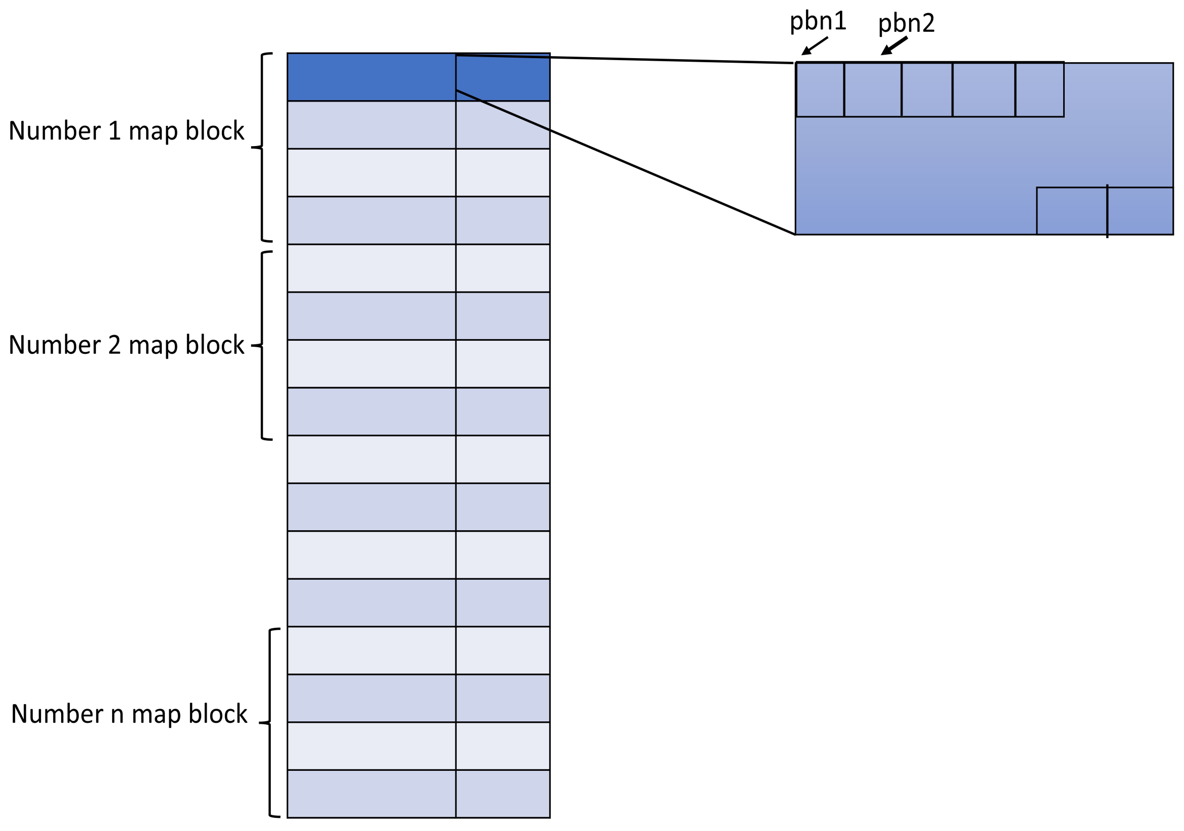
The map block, which held map data in some way, is only referred to as a block map for a block containing flash memory. FTL may be extended to a block to decide the best routing if the block is big enough to contain all of the map data. There is only one map block in this game. The block map is generated so often when only one map block is used that it cannot be erased. As a consequence, the number of map blocks is often used to minimise adverse circumstances. The map’s information, including the logical block pair number and physical block number, are also listed in one of the Places not included in the most recent update. One of the places not included in the most recent block map also reports information about the map, such as the logical block pair number and physical block number. In the field, physical block numbers are stored in the order in which they appear in the logical block list. Even, if a single sector is not big enough to hold the entire physical block number, several sectors are used. If the mapping information is modified as a result of the file’s write, the computer performs the recording. If the Map block pool has no unused sectors, the recording, and erase task must be performed to unlock the block map. The mapping tables may be cached into a RAM with a quick mapping lookup during the power outage.
4. Proposed Technique (RSLSP)
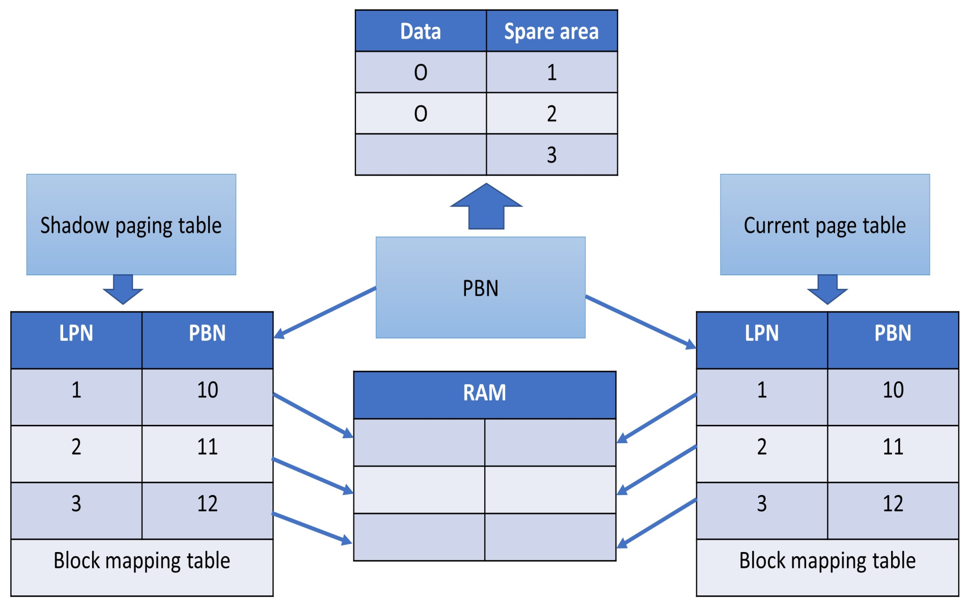
When the data has been modified or changed, we can use the shadow paging table to retrieve the old mapping information. The system would be corrupted if the mapping table is modified or changed [
5]. Our scheme, which employs shadow technology, is capable of resolving this issue and recovering the mapping table records as shown in
Figure 4. The basic idea is to take advantage of the shadow technological advantages and familiarise it with FTL algorithms. Our objectives are to integrate shadow algorithms into the FTL storage algorithm in order to retrieve mapping information.
The size of RAM used in FTL algorithm is important because it effects the overall device cost. The performance can be enhanced if a system has enough RAM. According to FTL and their RAM structures we can categorize them based on their RAM structures [
2]. Storing the logical to physical mapping information is the main purpose of RAM. Therefore, we can effectively find the physical flash memory location for reading or writing data. While the space information of free memory of flash memory allocated in RAM, we can maintain the memory space by an FTL algorithm. The RAM table is consisting of block mapping table, in the right one is the current page table and the left one is the shadow paging table of block mapping table, which allow us to recover from old mapping data when the information possesses some updating and modification.
4.1. Revisit Map Block Method
It is critical to think of a storage scheme for mapping eight. If a power-on operation happens, the mapping table must be recoverable. In the case of a sudden power-off, mapping information loss should be recoverable. As a result, these data must be saved in some kind of flash memory. There are two methods for storing mapping information in flash memory: the map block method and the per block approach. A map block technique places mapping data in distinct blocks with flash memory known as the map blocks. Most of the FTL-based implementation methodologies utilize several map blocks.
Figure 5 shows the procedure for map blocks and how they store information about mapping [
2].
Figure 5 indicates that the job must be completed if mapping information is changed or improves. If the map blocks pool has no unused sectors during the recording job, the erase operation must switch to another free map blocks. We can cache the mapping table in RAM for fast lockups [
5]. As a consequence, during the power-on process, we must reconstruct the mapping table in RAM. To use a flash memory in such a manner that a data block of a fixed size block unit can be read and registered as several disc sectors. There is a file system standard for magnetic discs called FAT that includes the use of a flash device. A read or write operation request block is used by the file system code to call application drivers in this configuration. The block is stored and recovered from the flash system driver modules. (Any removable computer, such as a full integrated ATA disc interface, can be flashed with a compact flash card and used with a regular disc drive.).
However, a basic linear flash block address on the map poses two issues: first, certain data blocks can be registered even more than others. Because of the wider magnetic disc, this current file does not pose a problem. This case is not avoided by the system [
22]. The mapping of the flash file system on the device’s commonly used erase machine, on the other hand, slows down access speed and the fast mode do time gradually runs out. This problem can be solved with a more complex block-to-use flash map. Technology is an immensely valuable method. Wear levelling technology is the name given to the mechanism of applying such a technique. The inability to remove flash units is the ID’s second issue. It is mapped onto a small data cube.
4.2. Revisit Shadow Paging
In this part, we will delve into the shadow paging recovery scheme. In a single-user case, the shadow paging recovery schema would not require the use of the log. For concurrency control, a log can be required. In order to retrieve a folder, shadow paging is used. N-pages-per-disk (or disc block)—known to be made up from blocks. When the “n-th” entry consists of a directory entry, it refers to the “i-th” number page in a database on disc. In contrast, if the database is configured, the directory is not too wide, and all of the reference pages from the database are viewed as pass-via disks-read/write. As, a transaction begins, the actual directory is copied to the shadow directory, which is the access point to the most recent or current page on the database disc. When the transaction is using the shadow directory, the actual directory will be transferred into the copy of disc-erase.
When you use the Write item to execute this process, a new copy from the updated pages in the database is made. However, it does not delete an existing copy. Instead, a new page is to be written to disc blocks that were not previously used in any other way. The existing entry in the directory will be changed to refer to new disc blocks. Moreover, the shadow directory which does not proceed to point toward a fixed disc block is not changed. When a transaction changes a page, all versions are maintained. Previous versions are referenced with the latest edition through a shadow directory as the existing directory.
It is necessary to dispose of the current directory to retrieve the error in the transaction execution and release the updated database pages. The database’s transaction state is visible by the shadow directory until it is executed, and the state is restored by the shadow directory. If a confrontation happens, the edit page is removed, and the database is restored to a state before a transaction was started/executed. Then, it performs the transaction that leads to an old shadow directory’s elimination. The strategies can be categorized as recovery NO-UNDO/NO-REDO strategies and they include data recovery as well as data loss and re-entry. It must be implemented in the shadow paging scheme in the concurrent transaction log as well as the checkpoint in a multi-user situation. One downside of shadow paging is that the modified database page shifts the disk’s location. This would be difficult to maintain the dynamic storage management technique linked database page in proximity to a disc besides the directory being wide. Furthermore, when a transaction is been performed, the overhead for creating a disc shadow directory should be a vital complication. To declare the list of available pages for potential use, it must be referenced by the revised shadow page directory. The page for transactions done is not further required. Another thing is that work must be performed as an atomic operation, such as flipping between the actual and shadow files as shown in
Figure 6.
4.3. RSLSP
To retrieve the block mapping table, we must build a non-volatile memory table. We can restore the block mapping table without missing any data if there is a sudden power loss as shown in
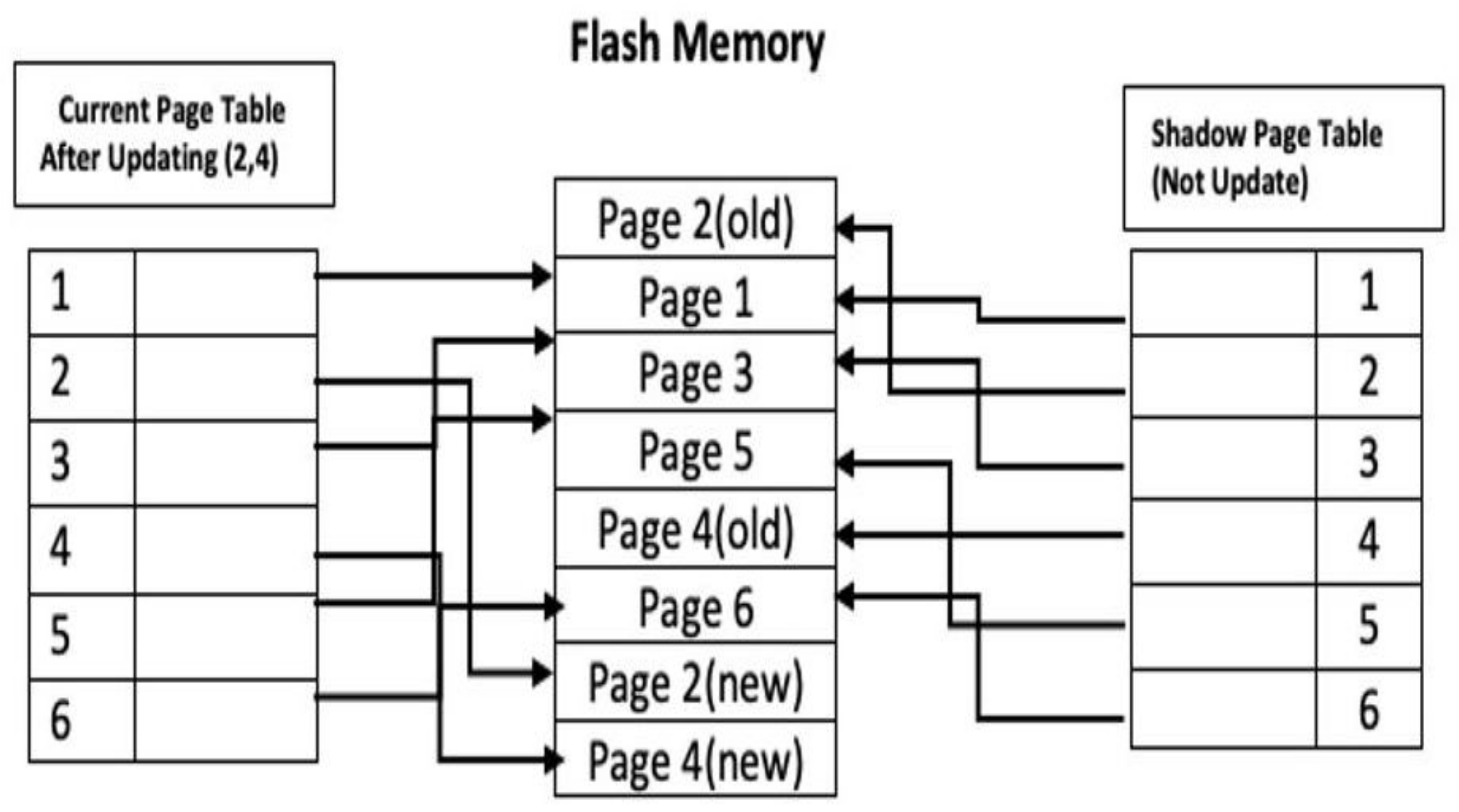
Figure 6. If an update to the block mapping table occurs, we will recover using the same method. As a consequence, we must keep the device in saving mode to avoid data loss. Calculating activating pages is the perfect strategy for recovering. We will then know how many pages we need to restore. The RSLSP recovery strategy takes into account flash memory. Maps are logical data units that have a set capacity and are referred to as pages. The page table, which makes one entry for each logical page of flash memory, is used to map pages into physical storage blocks. The actual page table and the shadow page table are used in this process. The entries in the current page table are used to refer to the disk’s most recent flash memory pages. When the transaction begins, a shadow page table is used to clone the actual page table. Following that, the shadow page table is saved to disc, and the actual page table is used for transactions. Entries in the actual page table can be modified during implementation, but they are never changed in the shadow page table. Both tables become similar after the exchange.
Overview of shadow paging: (1) Transactional modifications remaining in the buffers are pushed into a secure database. (2) The current page table is saved on disc. (3) In the special place, modify the disc address. The fundamental concept behind all wear-levelling techniques: The mapping presented by block number is referred to as the host. To transform a virtual block number to a physical address and sector number, use the following formula. When the virtual block is rewritten, it will overwrite those sectors where the new data is already being stored. Increasingly, new data will be written, and a business map on both the sector as well as virtual block is modified. The sectors, in general, can represent a fraction with a fixed-size erase entity. A sector usually takes up one of the flash pages in a NAND device. However, variable-length sectors may also be used in the NOR feature.
Consider the diagram above to grasp the idea. On pages two and four, two write operations are done. The new page table points to the old page two before beginning the write process on page two. When the write process begins, the following steps are carried out: To begin, look for any usable free pages in the flash memory. It copies page two to free page, which is represented by Page two after it finds free page (New). The existing page table points to the disk’s Page two (New), but the shadow page table points to the previous page two because it has not been updated. The updates have now been propagated to Page two (New), which is indexed by the existing page table.
4.4. RSLSP Approach
4.4.1. Shadow Paging Protocol
By leveraging the shadow paging in FTL, we have prevented data loss even in power loss scenarios too. The shadow paging technique is implemented by using the checkpoint period as follows:
Clears the metadata for the user.
Obtains pointers for user data.
Checks whether the index of a page is aligned and if the pages belong to the same group of alignment or not. Moreover, it also identifies the block successor.
Computes the period of a checkpoint.
In addition, the data recovery is performed with a setup of the journal. It first sets up an empty journal, then the buffer for the metadata is emptied and fixed parameters are set.
Calculate the first checkpoint that has the block. When the block contains either checkpoints, then it should have one existing in a first location of that checkpoint– In contrast, the block will be considered erasable.
Test if a checkpoint group is in ready state for reprogramming, however, allow it for the condition that is_free() should not have any way for differentiating between a programmed page and unprogrammed page with all-0xff bytes (on the other hand, it must be acceptable to reprogram this kind of page). We have tested with an unprogrammed group of checkpoint by checking if a first user-page is either programmed since the last erase (via testing the first page only through is_free). It will work if is_free was precise, since the writing of the pages was in order. If is_free, then we must check all of the pages for that group. It will also work, since the last page of a checkpoint group is ensured to have non-0xff bytes. Consequently, we return a value of 1 if a group is unprogrammed truly, or if this was programmed partially with all-0xff type user pages (that changes nothing).
Then, it finds the first checkpoint which contains the block, it also computes the final last checkpoint. Moreover, it finds the checkpoint which is last programmed. It also performs the linear scan for obtaining the last suitable and better checkpoint.
Afterwards, the settings are restored from the checkpoint.
To obtain the other free user of page, a linear scan is done. Then, calculate the raw pages number and checkpoint number between the tail and head. The upper limit, i.e., the user pages number is the overall difference between these.
Finally, when the error checks are performed then put the values in tails and heads, etc.
4.4.2. BAST Protocol
In BAST, basically, we are implementing the following techniques
Comparison class for use by FTL to sort the LogPageBlock compared to the number of pages written.
Detecting required number of bits for logical address size
Finding the required number of bits for block size and then Initializing block mapping table.
After that, we check that it fits inside the existing log block. Issue the request.
Write the current io to a new block.
In the end, do merge operations (n reads, n writes and 2 erases (gc’ed)).
Write page to the new data block.
Promote new log block.
Create BLOCK_SIZE reads.
Create BLOCK_SIZE writes.
Promote new block as data block.
Place data and log block into the invalidate list.
The last thing is updating the map.
5. Experimental Results, Comparison and Discussion
The authors in [
9,
10], suggest a power off recovery method for flash memory. Some papers that consider recovery schemes for flash memory look at recovery schemes for block mapping tables. If there are data in the block mapping table, the system will not be able to be restored. In this situation, the proposed idea’s consistency with current FTL is excellent, as it applies to block mapping recovery, and the compatibility with existing FTL in [
9] is excellent for the same reasons. The spare field is 1/32 the size of a data sheet, and users cannot see it. The In-Page backup scheme stores mapping information in an equally dispersed manner. Even with the excess cost, this scheme uses the spare field without incurring the cost of run-time backups. We cannot only use PORCE [
9] as a counter-measure to the suggested proposal. PORCE can only be used with block level routing systems, and its recovery coverage differs significantly from that of our proposed proposal. Since it is successful to wait for an entry operation sequence data with a spatial trend locality, the PORCE has almost allowed an increase in output in terms of latency. Our suggested proposal, on the other hand, outperforms the others and is consistent with the FTL algorithm.
The suggested solution’s key suggestion is to keep the mapping information table in the spare table. Since the cost of operating the backup mapping table can be reduced if the corresponding table is spread in the area alternative, the cost of updating the page programme operation is absorbed into the data page programme process. Return all rescue operations that aim to use accrued a few pages in the page map entry or reduce the block map entry technology to reduce page reads. Since the largest NAND flash memory processing block has another restriction, the page must be continuously programming from the first to the last page (so random page programming is strictly prohibited) blocks if the big memory block NAND [
23]. If the large memory block NAND [
24], although the largest NAND flash memory programming block presents another constraint, the page must be continuously programming from the first page to the last page (so, the random page programming is prohibited stringently) blocks. We can either use a signature-based correspondence table to circumvent this control strategy or we can use a combination of both. In a nutshell, these technologies can be written by a backup cost to delete the mapping table pages in each operation to increase run-time efficiency and memory recovery delayed by a decrease to an appropriate level of the user [
10].
Table 1 shows the comparison result.
However, since these strategies necessitate the use of an additional flash programme for each mapping table update, storage systems can incur additional overheads. Furthermore, they spend a considerable amount of time restoring metadata from the backup field, particularly in In-Page backup. In certain FTL algorithms, a logical block can be mapped to no more than two physical blocks. In Quick [
25], a logical block may be mapped to several physical blocks. It was split into data and buffer blocks. PORCE aims to provide power off recovery protocols that take into account wear-levelling modules without requiring significant changes to FTL algorithms. The scheme’s implementation objectives are to recover from power outages, reduce output loss during normal operations, and recover from faults during reclamation operations. We can see in our suggested scheme that we deem a routing table recovery strategy and that we can keep the device running even though there is a power outage. When the FTL needed to marge any bricks, they used the PORCE to set the completion flag to TRUE and label the details of the blocks to map blocks.
As a result, for any block merge process, they use two page changes to map blocks. If we look at this point, we can see that the map blocks must be combined regularly. The proposed concept considers recovering mapping table information in the event of a malfunction, while the PORCE reads whole pages in map blocks. Many FTL algorithms benefit from this strategy because it improves the recovery scheme in flash memory. However, using the shadow page table, no recovery is needed after a device collapse, and new transactions will begin immediately. The suggested concept would not allow for the overhead of writing log books. The recovery is easy, and there is no need to delete the flash memory. In addition, pages that are not linked from the current/shadow page table must be liberated (garbage collected). We know the paging number in order to know how many paging recoveries required. Herein, we assume the capability of flash memory is 128 MB (i.e., it entails 8192 blocks). Furthermore, 1 block is equal to 16 KB.
So, we can calculate how many paging we need as following:
- -
128 MB
- -
1 Block = 16 KB
- -
128 MB/16 KB = 8 × 210 = 8092 Blocks
- -
8092 Blocks/256 = 32 pages the size of one block
K: Address expression size of a page or block (bytes). Let K be 4. After the calculation, it is observed that the recovery page requires more than RSLSP. As a result, the map block arrangement latency takes up more time than usual. The parameters of flash devices are shown in
Table 2, while the traces of the experiments are denoted in
Table 3.
We used the RSLSP protocol in BAST, which is one of the FTL algorithms, to test its performance characteristics. Our protocol, on the other hand, can be used in any FTL algorithm.
Table 3 displays the four traces that we used to test our protocol in the experiment. Various forms of traces were used in the experiment. The experimental findings of the RSLSP scheme, without recovery scheme, and with recovery scheme are seen in
Figure 7,
Figure 8,
Figure 9,
Figure 10,
Figure 11,
Figure 12,
Figure 13 and
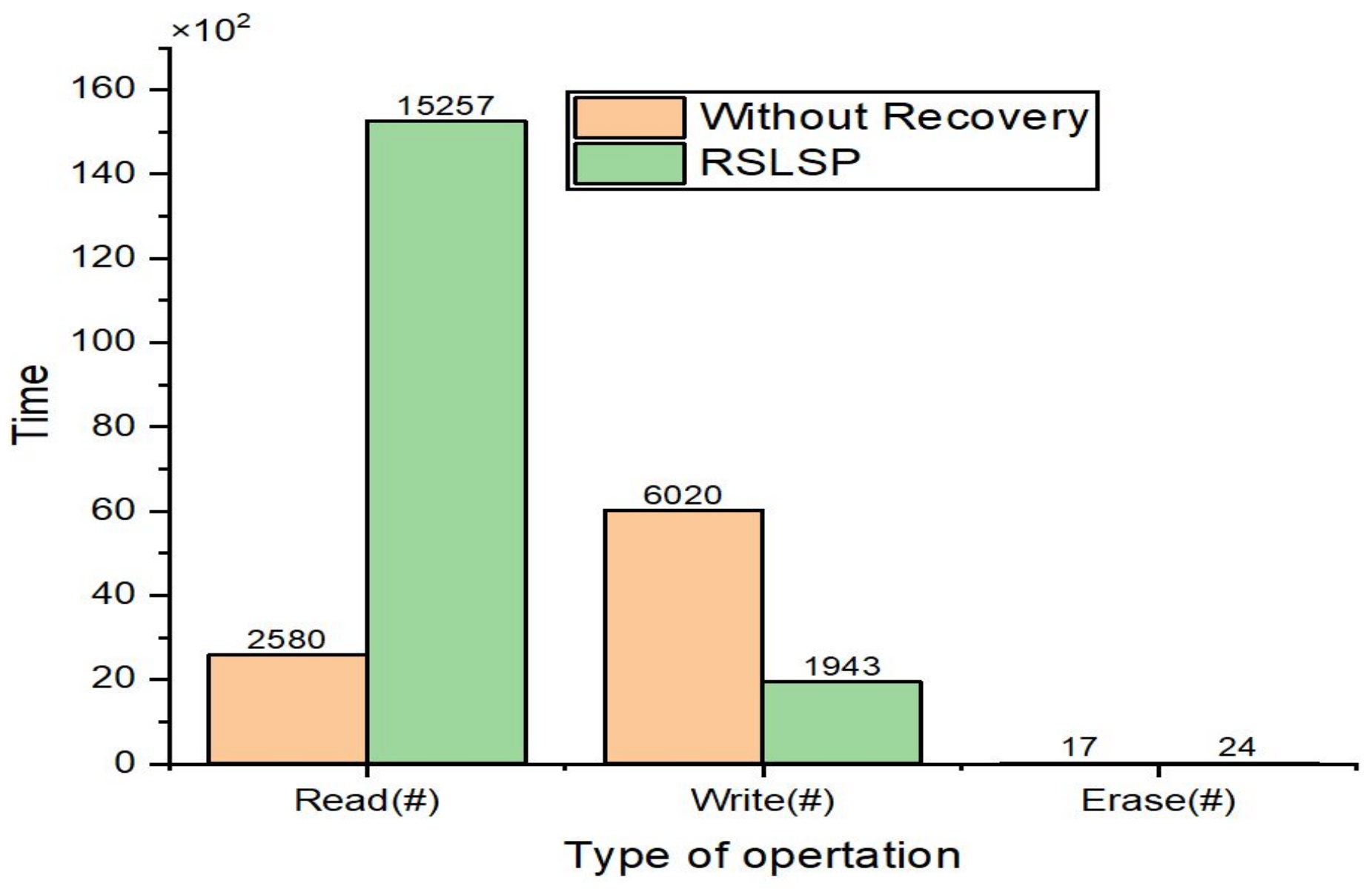
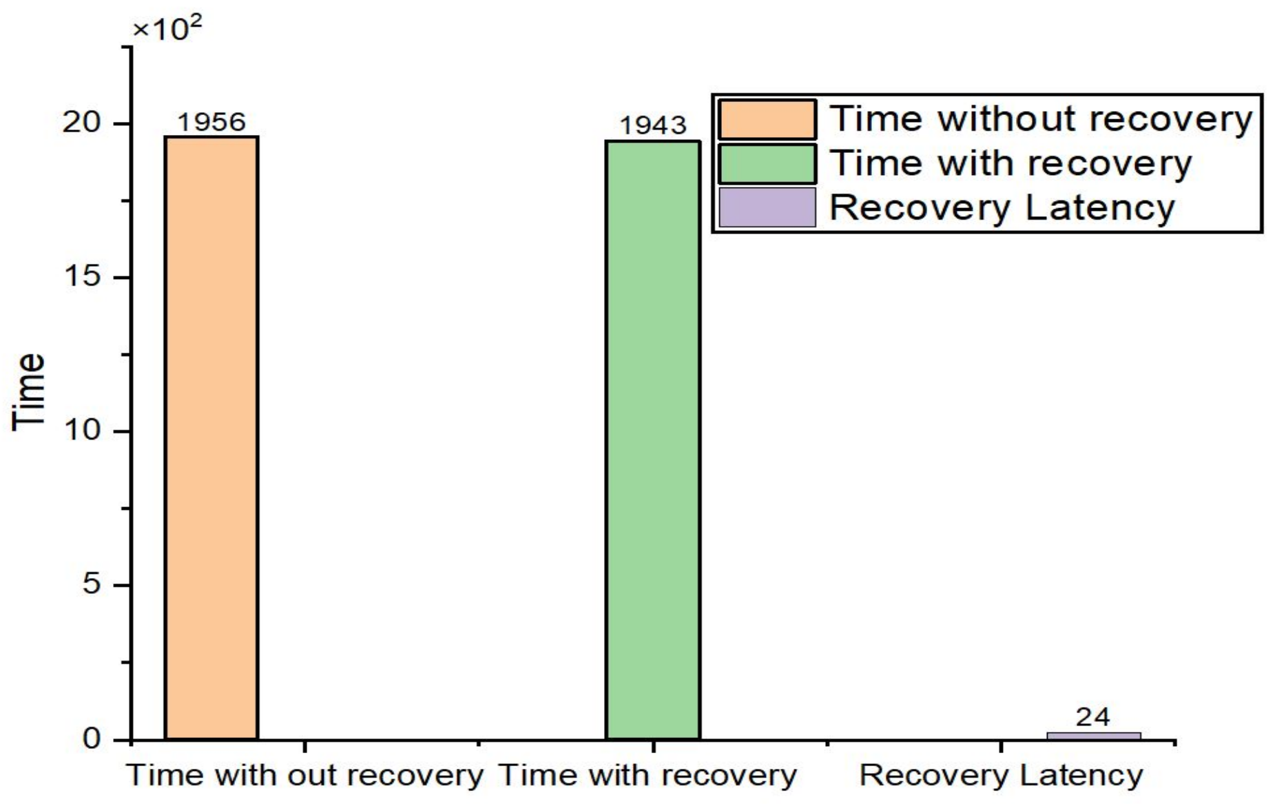
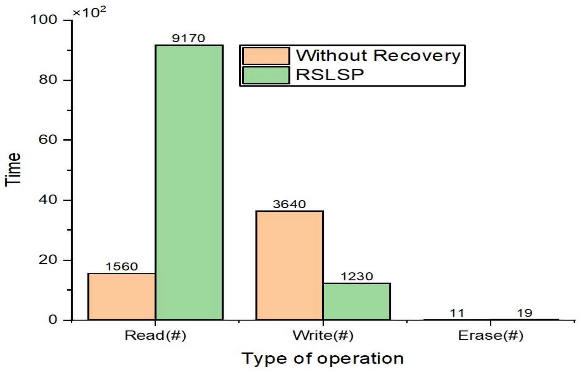
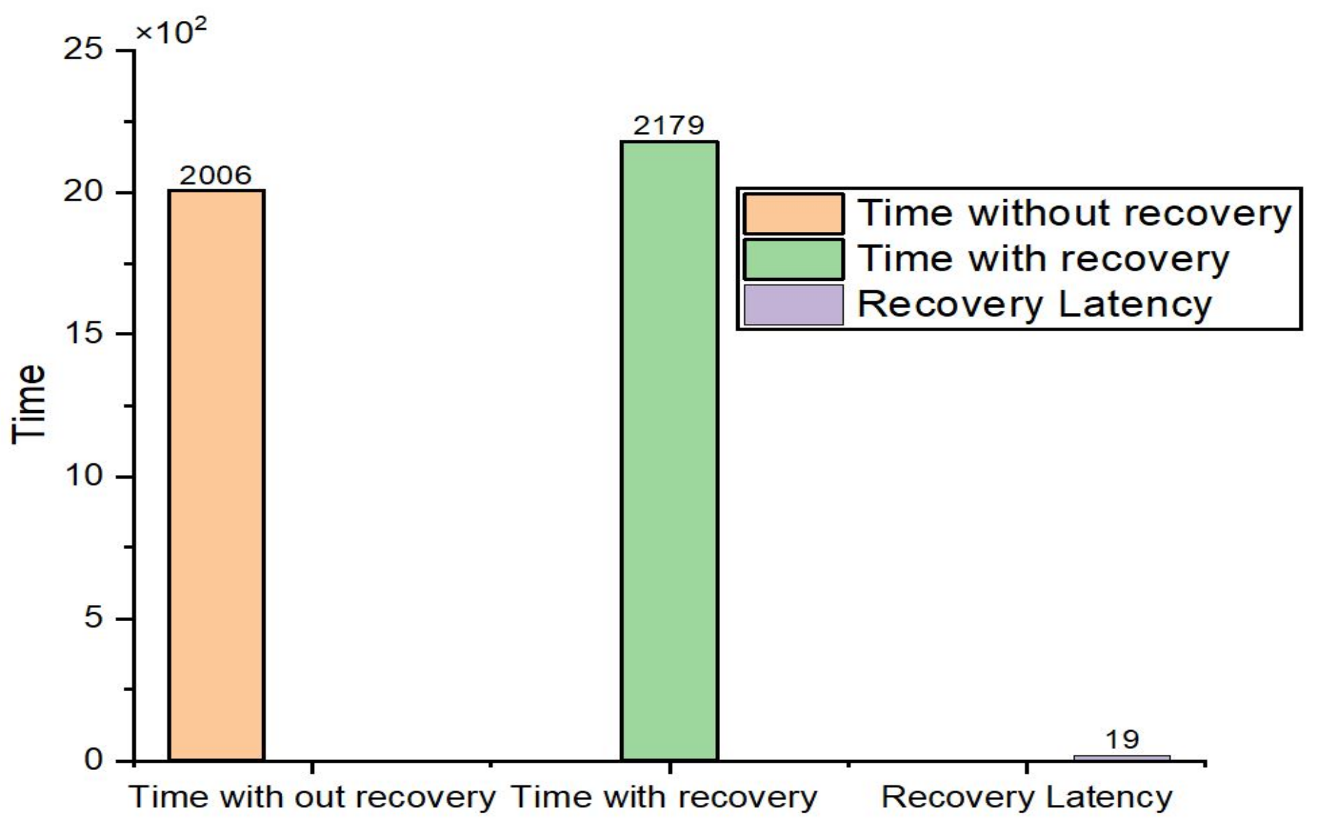
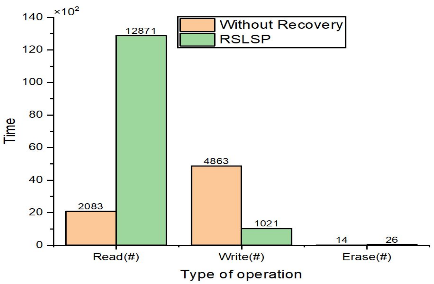
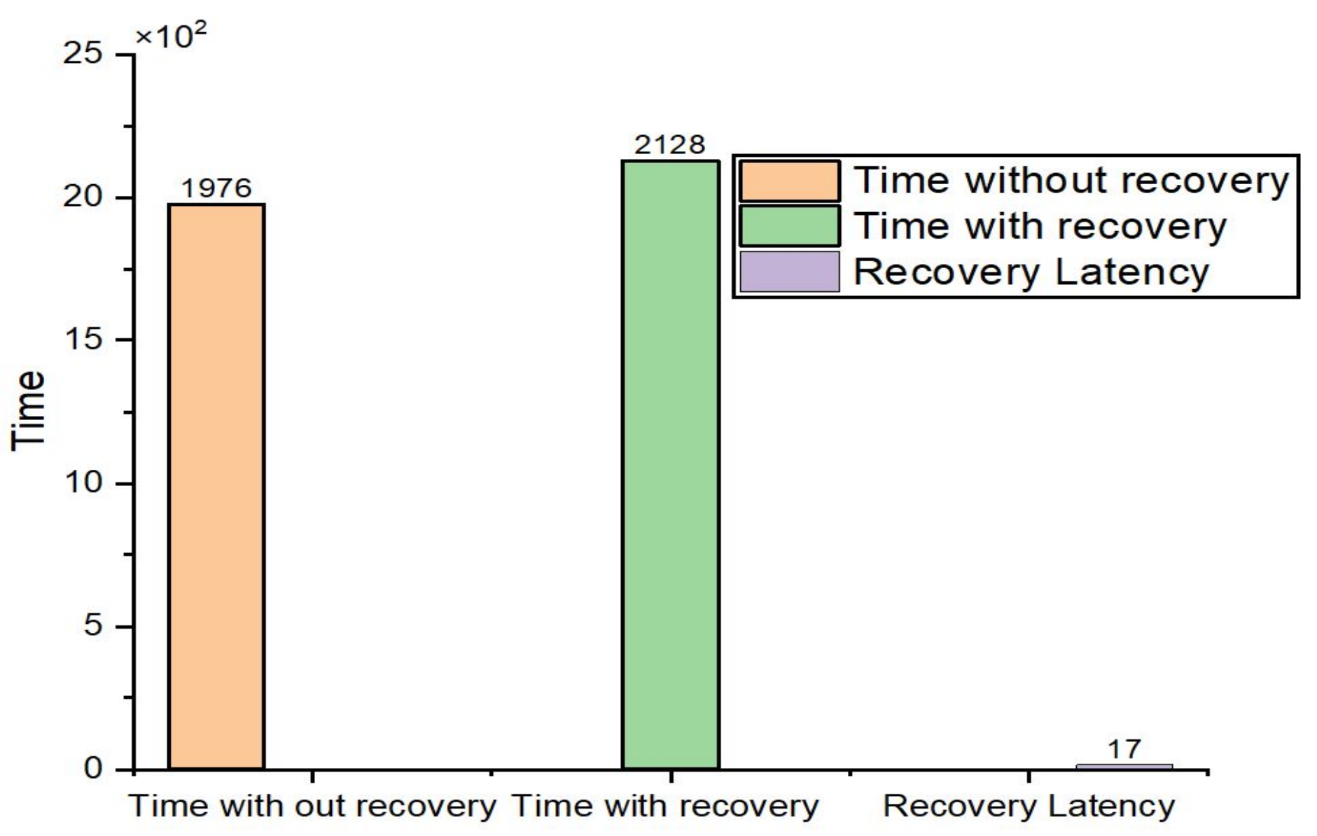
Figure 14. We counted the number of write, read and erase operations and the amount of time taken to complete the task. Furthermore, we also consider the recovery latency. We can see the RSLSP scheme results for four patterns.
Figure 7 and
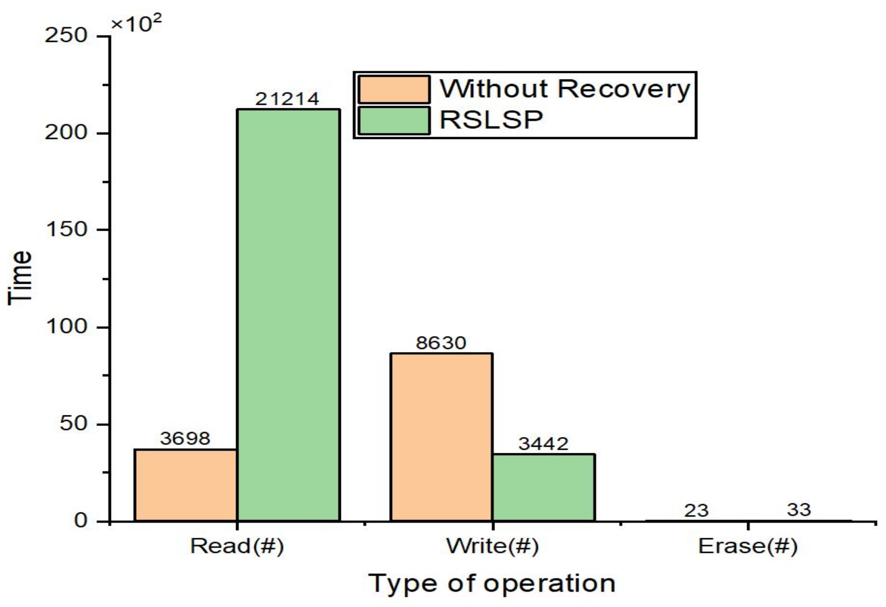
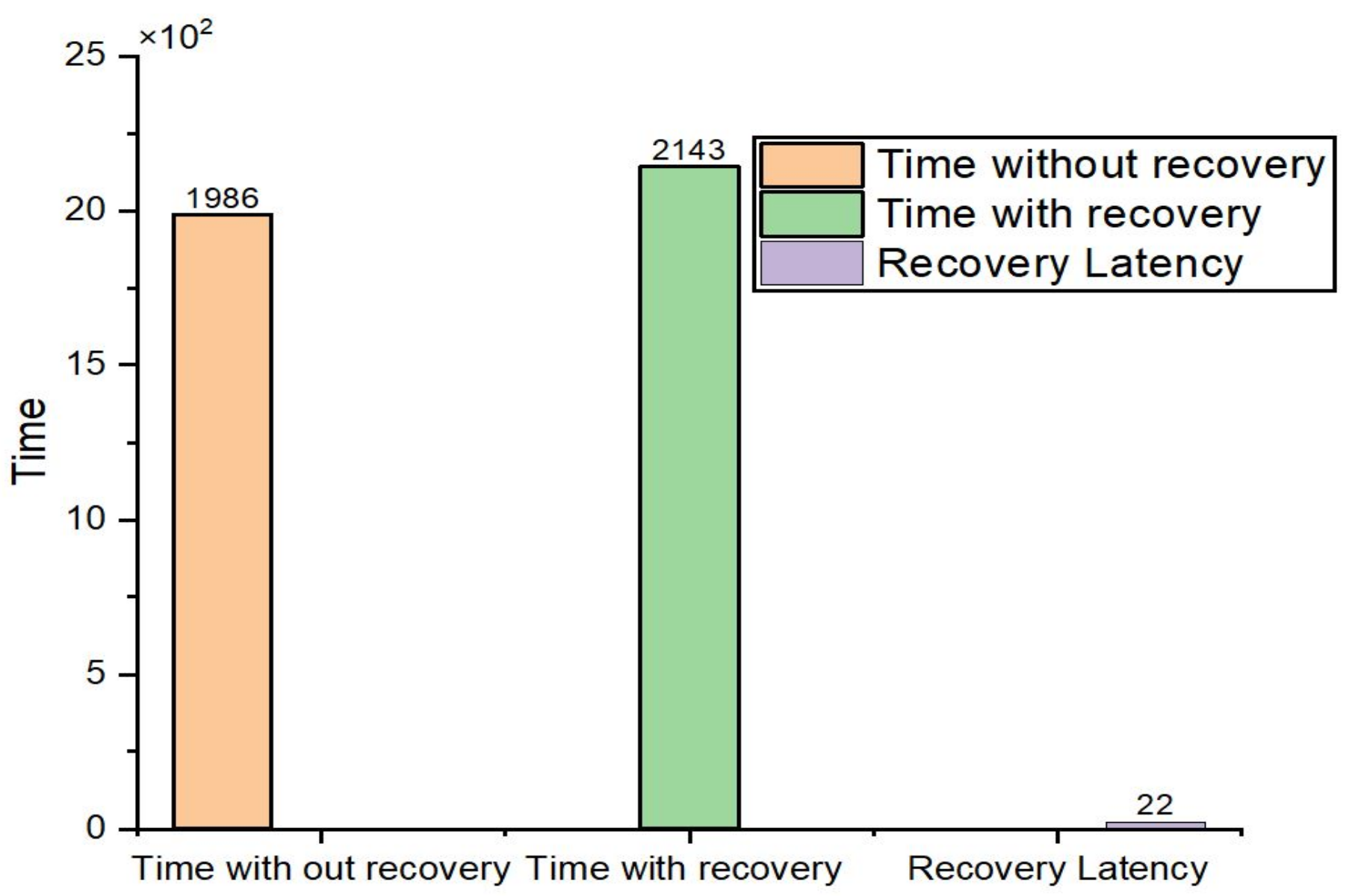
Figure 8 show the results for pattern A. Pattern B results are indicated in
Figure 9 and
Figure 10. Moreover,
Figure 11 and
Figure 12 show the results for pattern C. Finally, the results of pattern D are revealed in
Figure 13 and
Figure 14. These figures show that the RSLSP scheme requires a small time of recovery latency to guarantee system safety. In addition, the performance gap between our scheme and without recovery scheme in read and write operations is in accordance with the characteristics of shadow paging technique. The proposed RSLSP shows the effectiveness in terms of the recovery latency and time. The results are cross verified using different patterns.


