Article

Design of Automatic Correction System for UAV’s Smoke Trajectory Angle Based on KNN Algorithm

Department of Computer and Communication Engineering, National Kaohsiung University of Science and Technology (NKUST), Kaohsiung 807618, Taiwan
*
Author to whom correspondence should be addressed.
Electronics 2022, 11(21), 3587; https://doi.org/10.3390/electronics11213587
Submission received: 23 September 2022 / Revised: 25 October 2022 / Accepted: 31 October 2022 / Published: 3 November 2022
(This article belongs to the Special Issue Knowledge Engineering and Data Mining)

Abstract

:
Unmanned aerial vehicles (UAVs) have evolved with the progress of science and technology in recent years. They combine high-tech, such as information and communications technology, mechanical power, remote control, and electric power storage. In the past, drones could be flown only via remote control, and the mounted cameras captured images from the air. Now, UAVs integrate new technologies such as 5G, AI, and IoT in Taiwan. They have a great application value in a high-altitude data acquisition, entertainment performances (such as night light shows and UAV shows with smoke), agriculture, and 3D modeling. UAVs are susceptible to the natural wind when spraying smoke into the air, which leads to a smoke track offset. This study developed an autocorrect system for UAV smoke tracing. An AI model was used to calculate smoke tube angle corrections so that smoke tube angles could be immediately corrected when smoke is sprayed. This led to smoke tracks being consistent with flight tracks.

1. Introduction

Flexible, safe, stable, high-speed, and low-cost UAVs have been developed in the past few years. This was achieved due to the continuous development of the modules, including the process materials, electric power storage, and sensors [1,2,3,4,5,6,7,8,9,10,11,12]. So far, UAVs have been widely used in civilian, commercial, and government units. Industrial UAVs can be applied in environmental monitoring, infrastructure inspection, disaster or accident rescue, agriculture, forestry, fishery, animal husbandry management, spatial information measurement, land and guard patrol, media communication, telecommunications services, home delivery logistics, and the military. Most application fields can be further subdivided. For example, environmental monitoring can be divided into the monitoring and investigating of air pollution, oil pollution, nuclear pollution, marine pollution, and river pollution, and even includes the study of weather changes. Many types of infrastructure are subjects for inspection, including roads, railways, transmission towers, and oil fields. Regarding the rescue, drones can be used for video recording, a real-time image transmission, and material delivery. Regarding the environmental conditions, there are waters, mountainous areas, or buildings. Agriculture, forestry, fishery, and animal husbandry management includes pesticide or fertilizer spraying and the observation of crops, trees, pastures, and fish farms. The work in spatial information includes aerial mapping, a terrain attribute classification and survey, a national land survey, urban planning, a land survey and development, water control and flood control planning, and 3D real scene modeling. Guard patrol includes a coastal patrol, criminal chasing, and general security work. Regarding media communication, in addition to providing real-time news about disaster areas and war zones, they can be applied to business and tourism marketing. There are diverse applications in the military, and they can be used as reconnaissance aircraft, target aircrafts, and bombers. Therefore, industrial UAVs have unlimited business opportunities. In Ghana, there have been about 275,000 UAVs flying and delivering medical kits containing vaccines [13]. The edge computing technology is used in UAVs for the power transmission line inspection [14].
On many major holidays and celebrations in Taiwan, people can see the colorful smoke from fighters flying by the military in the sky. In addition to the purchase of fighters, such activities often cost a lot of money (military aircraft maintenance, personnel training, and aviation gasoline), which consumes gasoline and imposes a burden on the environment. Therefore, the use of UAVs carrying smoke tubes for aerial smoke spraying has grown in recent years. Today, most UAVs are mainly powered by electricity and do not emit exhaust gas like gasoline engines. Moreover, UAVs cost less than traditional fighters in smoke spraying. For example, in Taiwan, according to the Regulations of Drone of the Civil Aeronautics Administration [15], if pilots hold G2 licenses (flying more than 400 feet above the ground or water, operating beyond the range of visibility, dropping, or spraying objects) and UAVs are registered in the UAV system of the Civil Aeronautics Administration and apply for airspace in advance, regulatory restrictions can be exempted and UAV shows with smoke can be performed.
UAVs cannot carry large smoke tubes and smoke tubes installed at different positions are susceptible to the natural wind and lead to a smoke track offset. In this study, detectors and smoke tube correctors were installed above the UAV. An AI model was used for training to correct the offset tracks. In this way, small low-altitude UAVs could achieve the same visual effects as traditional high-altitude fighters in UAV shows with smoke, in a way which is cheap and environmentally friendly.

2. Materials and Methods

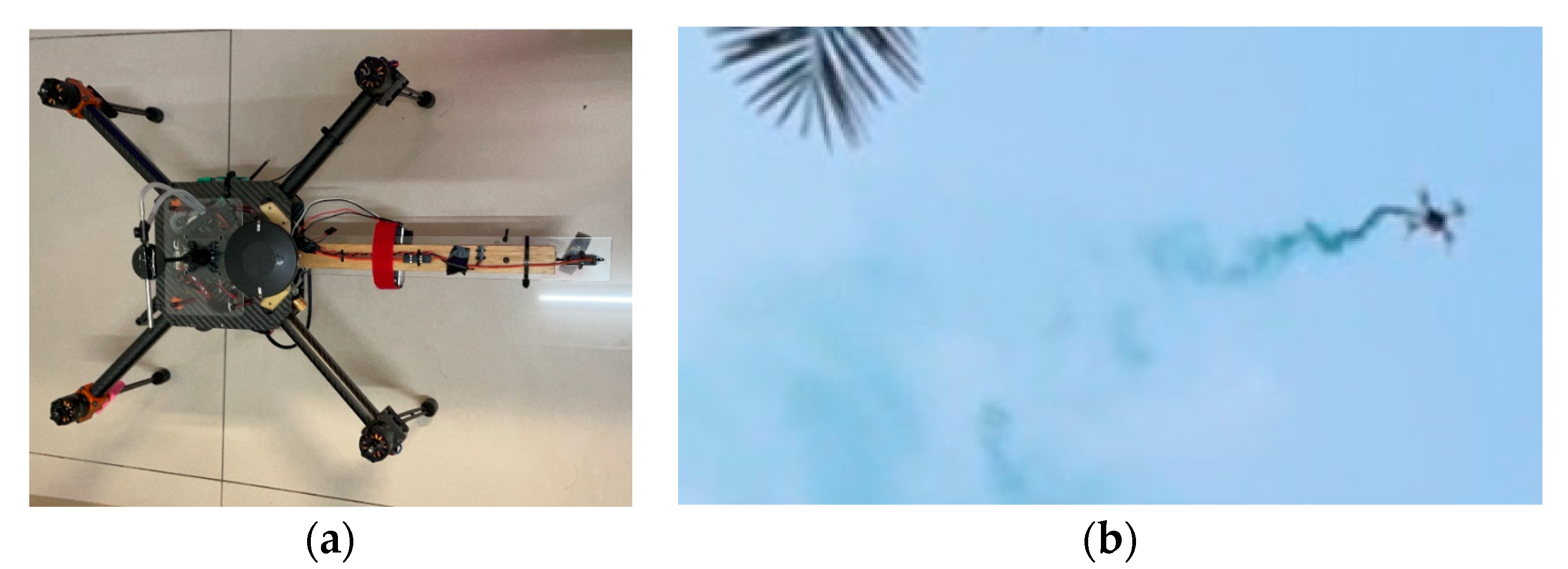
2.1. Unmanned Aerial Vehicle

The UAV used in this study has the following basic flying parts: a flight controller, motor, electronic transmission, frame, and GPS positioning module. In addition, a servo motor, smoke tube, Raspberry Pi, 4G communication module, and lithium battery are installed. The overall weight is about 2.5 kg. Considering the motor load in the flight process and flight time, a UAV with a wheelbase of 450 mm and an EDU450 carbon fiber frame was selected [16], as shown in Figure 1.
A Pixhawk2 CUBE consisting of two processors was used as the flight controller of the UAV. In the Pixhawk2 CUBE, the main processor was STM32F427 V3, and the coprocessor was STM32F1. The built-in sensor included a tri-axis accelerometer (L3GD20), an accelerometer and magnetometer (LS303D), a gyroscope (MPU9250), and a barometer (MS5611). With a weight of 73 g, this light and efficient flight controller supported open-source flight control software PX4 and Ardupilot. Three–eight axis multi-rotor models and multiple interfaces, including the Mavlink interface, I2C interface, and PWM signal output system, are used in this study. Raspberry Pi 3B+ has a USB interface which can be used for Internet access apart from the built-in WiFi card. If the 4G network card fails, it can switch to the built-in WiFi [17], a backup network, as shown in Figure 2.

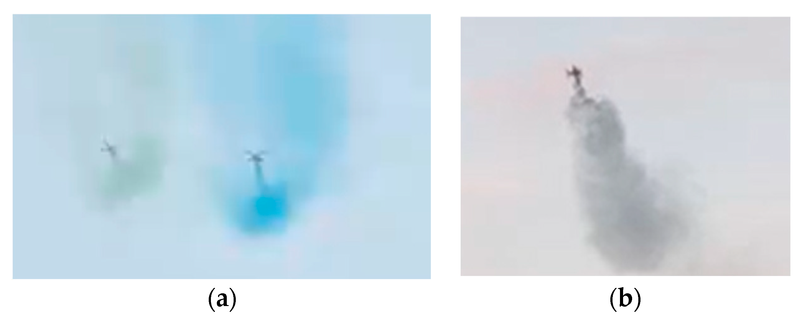
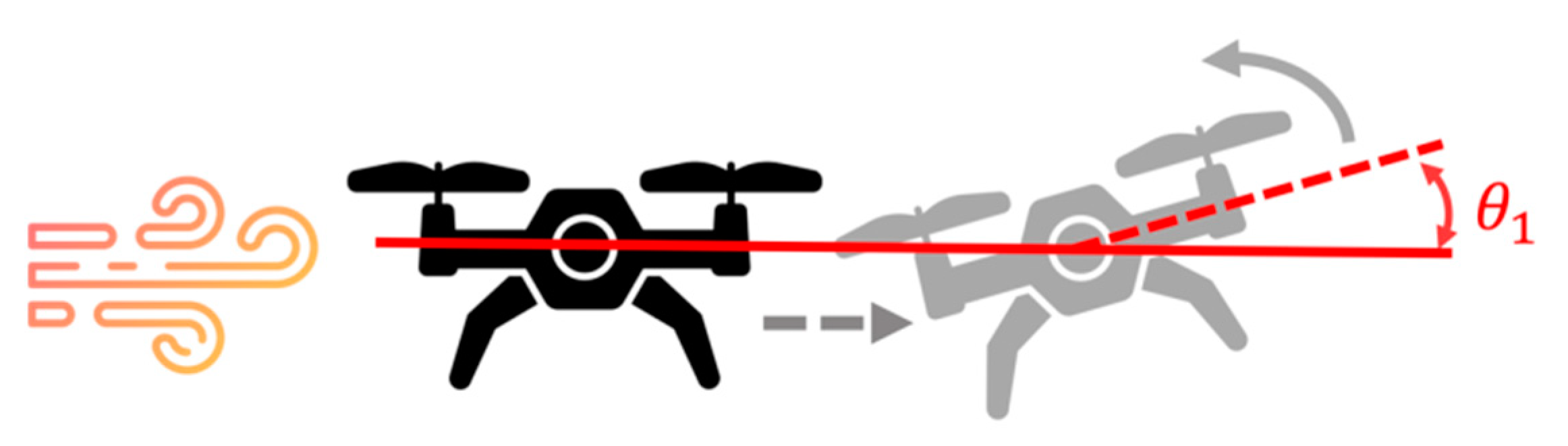
2.2. Smoke Tube Position

In this study, a four-axis multi-rotor UAV was used for the experimentation. The smoke from the smoke tube is vulnerable to the natural wind and tube position, leading to a smoke track offset. In that case, the audience is unable to enjoy the performance. As shown in Figure 3, when the smoke tube was placed directly below or above the UAV, the smoke from the smoke tube was affected by the downdraft generated by the propeller. Regardless of the rotation of the servo motor and adjustment of the smoke spraying direction, the smoke would be affected by the airflow and sprayed downward. In this study, self-made 3D material parts were attached to the UAV. An additional extension area was built to install the servo motor and smoke tube for adjusting the spraying angle. This is to prevent the influence of downdraft generated by the propeller as much as possible and to make the smoke from the smoke tube be sprayed backward, as shown in Figure 4a. To avoid the pendulum effect and the excessive output energy of the rear motor, the length of the extension area is adjusted to 29 cm after multiple outdoor flight tests. The aerial testing shows that the smoke track is significantly improved, as shown in Figure 4b. After improving the smoke emission direction, the track angle correction was discussed below, so that the audience could enjoy the best effect of the smoke track.

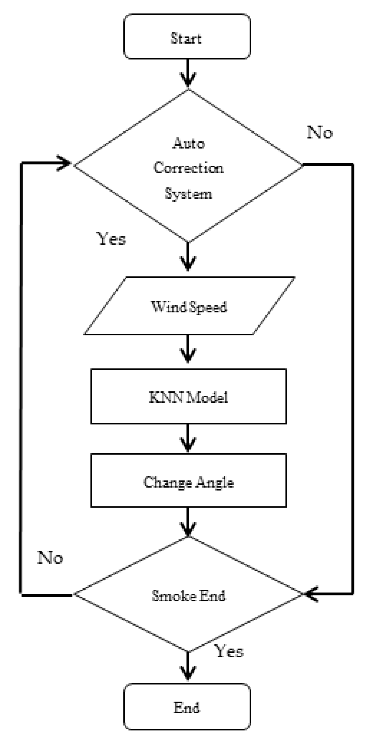
2.3. AI Model Selection and Design

K-nearest neighbors (KNN) are one of the most popular machine learning algorithms. It has been widely used in HPC applications, such as image/video retrieval, big data analysis, machine learning, and computer vision [18,19]. It is a nonparametric statistical method for regression and classification. The K-nearest training samples in the feature space ware input [20,21] and the k-value were used to determine which classification group the data were nearest to. The classification criteria were decided by majority voting, and the Euclidean distance was used to calculate the distance, as shown in Equation (1).
P = ( x 2 x 1 ) 2 + ( y 2 y 1 ) 2
In the KNN classifier, the output was the group classification, and its neighbors determined the category corresponding to the input object by a majority voting. KNN adopted the vector space modal for a classification, and objects in the same category were highly similar. The similarity could be calculated by the known category cases to evaluate the possible categories of the input objects. The training samples were multi-dimensional eigenspace vectors, in which each training sample had a classification label. The algorithm included eigenvector access and training sample labels at the training stage.
The KNN classifier assigns a weight of 1/k to the k-nearest neighbors and zero to all other neighbors. This can be applied to the weighted nearest neighbor classifier. The weight wni is given to the nearest neighbor i. In (2), a similar result holds for the strong consistency of the weighted nearest neighbor classifier [21].
i = i n w ni = 1
Let C n wnn denote the weighted nearest classifier with the weight { w ni } i = 1 n . According to the regularity condition of the category distribution, the excess risk has (3) an asymptotic expansion.
R R ( C n wnn )   R R ( C Bayes ) = ( B 1 s n 2 +   B 2 t n 2 )   { 1 + o ( 1 ) }
s n 2 = i = i n w ni 2
t n = n 2 d   i = i n w ni   { i 1 + 2 d ( i 1 ) 1 + 2 d }  
The optimal weighting method {   w ni *   } i = 1 n is used to balance the two items above. Let k * =   B n 4 d + 4 , (6) correspond to i = 1, 2, …, k, and w ni * = 0 correspond to i = k + 1, …, n. After using the optimum weight, the dominant term in the asymptotic expansion of excess risk is O ( n 4 d + 4 ) .
w ni * = 1 k *   [   1 + d 2 d 2 k * 2 / d   {   i 1 + 2 / d ( i 1 ) 1 + 2 / d   }   ]
At the classification stage, k is a user-defined constant. A vector without a category label (query or test point) will be classified into the most frequently used category among the k sample points nearest to the point.
When flying in the air, the UAV is affected by the crosswind wwind and deviates from its route. At this point, to correct the route, the flight controller will give a Roll value to adjust the pitch angle θ1 of the UAV, as shown in Figure 5. When the airframe is corrected, an angle adjustment θ2 is given to the smoke tube to make the smoke tube turn to the windward face to face the direction the wind comes from, as shown in Figure 6. According to the angle adjustment θ1 of the flight controller and the angle θ2 of the smoke tube, the direction and magnitude of the wind the UAV is exposed to in the air can be known, as shown in Equation (7).
w wind     θ 1 +   θ 2
Based on the above conclusion, the direction and magnitude of the wind are related to the value of θ 1 . The operator can adjust θ 2 according to the value of θ 1 when flying the UAV. θ 1 and θ 2 will be trained by the machine learning-based KNN classification method, and their relationship is shown in Equation (8).
w     θ 1     θ 2

3. Experimental Results and System Validation

During its flight, the UAV is affected by the natural wind and deviated from its course. At this point, the flight controller corrects the pitch angle in real-time to make the UAV return to its course. Its flight direction was mainly changed by correcting the pitch, yaw, and roll parameters. In addition to the airspeed meter sensor installed above the UAV, the three sensing values of the pitch, yaw, and roll parameters of the UAV can be used to learn the changes in the wind fields in the air.
Five angles, namely −60°, −30°, 0°, 30°, and 60° were designed in this study. These angles are the output y to be estimated by the KNN model. The input features include the pitch, yaw, roll, and airspeed meter values read from the flight controller. A KNN model was built for training.
Finally, the trained model was stored in the Joblib package and then put into the Raspberry PI in the UAV. Later, the designed system was used to read the model so that the real-time wind speed data read could be directly put into the AI model in the Raspberry PI for calculation. The results could be transmitted to the flight controller via the system to adjust the servo motor that controlled the smoke tube direction. It helped adjust the smoke tube to the optimal angle. The correction flow chart is shown in Figure 7.
As the UAV which was selected could not be fitted with a larger smoke tube, each spraying took about 30 to 40 s. The operator could collect about five pieces of data on each flight, which is not much. During the training, the pitch, yaw, roll, and airspeed meter data were put into the KNN model, and the accuracy was 50%. To improve the accuracy, more data is required. Therefore, the pitch and yaw were discarded, and the roll value was kept. The UAV was designed to fly back and forth in a straight line automatically. In the case of the deviation caused by a crosswind, the UAV could return to its route mainly by correcting the roll value. A roll value of 0 indicates that the UAV flew horizontally without any roll. A positive roll value indicates that the wind blew from the left side of the UAV. A higher value represents a higher wind speed. On the contrary, a negative roll indicates that the wind blew from the right side of the UAV. A smaller value reflects a higher wind speed. In this study, the roll value was collected to determine the speed and direction of the wind. This is to make up for the limitation of the airspeed meter under the breeze. The roll value was sensitive and thus could detect detailed data. In this study, 64 data items from the database were put into the AI training model, and the accuracy was 71%, as shown in Figure 8.
The roll data read by the UAV was recorded and put into the KNN model for testing. The test data and predicted angles are shown in Table 1. The table shows that the rolls and angle corrections were as expected. The smoke tube should have been shifted to the right when the roll was positive and left when the roll was negative.
Images taken behind the smoke tube show that the smoke tube could automatically change the direction and angle according to the direction and speed of the wind. Figure 9 shows that the UAV deviated to the left due to the wind from the right side. The roll of the angle correction to the right given by the flight controller was 0.061363. The smoke tube should be adjusted 30° to the right according to the calculation by the AI model. Figure 10 shows that the UAV deviated to the right due to the wind from the left side. The smoke tube should be adjusted 30° to the left, according to the calculation by the AI model.
The smoke from the smoke tube would be adjusted to the direction of the windward face. Based on the wind speed, the smoke tube would be adjusted to 30° or 60°. In this case, when the windward face of the UAV was in the front and rear directions, the smoke tube angle would not be adjusted.
Based on the observation of the actual flight, an accuracy of 71% indicated a significant improvement. Figure 11 illustrates the case without correction by the AI model. From the audience’s angle, it could be clearly seen that the track (yellow arrow) of the smoke from the smoke tube was offset due to the natural wind. Figure 12 shows the case with a correction by the AI model. From the audience’s angle, the smoke from the smoke tube could be observed (yellow arrow). Despite the influence of the wind field in the air, the smoke track could be manipulated to be almost the same as the flight route.

4. Conclusions and Future Work

In this study, Raspberry PI was used as the microcomputer for transmissions with the server. The flight data were received to control the smoke tube and sensor of a quad-axis UAV. To avoid the influence of the airflow, 3D-printed parts were used to refit the UAV. Its frame was extended to install a smoke tube and an electronic igniter so that the smoke tube could be lit for shows with smoke. As the smoke from the smoke tube was susceptible to the natural wind and became offset, a servo motor was installed to adjust the direction of the smoke from the smoke tube. A manned aircraft flew to record the angle adjustment, wind direction, and wind speed. The KNN was used to train a modified AI model. After applying the AI model to the Raspberry PI, the UAV emitted smoke in the air. The Raspberry PI and the flight controller could directly read the wind field data, and the angle could be immediately calculated and then sent back to the flight controller if it needed to be corrected. In this way, the spraying angle of the smoke tube could be adjusted immediately to make the smoke track the same as the flight route as much as possible. According to the results, the correction accuracy was 71%, which can demonstrate the difference between before and after the correction.
In the past, fighters sprayed smoke in the air to celebrate major festivals, which was expensive and polluted the environment. Our design is expected to make UAV shows with smoke possible on small occasions so that such events can be enjoyed on many occasions other than major festivals. The UAV designed by us is powered by electricity. Compared with a fuel-powered aircraft, it causes less environmental pollution and is cheaper.
The architecture in this study was designed for single UAVs. If the information of multiple UAVs can be displayed simultaneously on the web page and the crowd control can be carried out through function buttons on the web page, multiple shows with smoke can be performed simultaneously to spray. As for the collection of the wind speed data, this study collected various data, such as the roll, pitch, yaw, and anemometer values. Due to insufficient sample data, only the roll data were used for the machine learning. If more data can be collected in the future and all data collected can be imported for machine learning, the AI model will be more effective, and the overall correction effect will be perfect.

Author Contributions

Conceptualization, P.-Y.C. and W.-Y.C.; methodology, W.-C.H. and W.-Y.C.; resources, P.-Y.C. and W.-C.H.; writing—original draft preparation, P.-Y.C. and W.-Y.C.; writing—review and editing, W.-C.H. and W.-Y.C.; visualization, W.-Y.C.; supervision, P.-Y.C. and W.-C.H. All authors have read and agreed to the published version of the manuscript.

Funding

This research received no external funding.

Data Availability Statement

Not applicable.

Conflicts of Interest

The authors declare no conflict of interest.

References

  1. Valavanis, K.V. Advances in Unmanned Aerial Vehicles—State of Art and the Road to Autonomy; Springer: Berlin/Heidelberg, Germany, 2007. [Google Scholar]
  2. Papa, U. Embedded Platforms for UAS Landing Path and Obstacle Detection: Integration and Development of Unmanned Aircraft Systems; Springer: Berlin/Heidelberg, Germany, 2018; Volume 136. [Google Scholar]
  3. Lillian, B. FAA Predicts Future UAS Growth. 2019. Available online: https://unmanned-aerial.com/faa-predicts-future-uas-growth (accessed on 15 May 2020).
  4. González-Jorge, H.; Martínez-Sánchez, J.; Bueno, M.; Arias, P. Unmanned Aerial Systems for Civil Applications: A Review. Drones 2017, 1, 2. [Google Scholar] [CrossRef] [Green Version]
  5. Sigala, A.; Langhals, B. Applications of Unmanned Aerial Systems (UAS): A Delphi Study Projecting Future UAS Missions and Relevant Challenges. Drones 2020, 4, 8. [Google Scholar] [CrossRef] [Green Version]
  6. Department of Transportation. Unmanned Aircraft Systems (UAS) Service Demand 2015–2035: Literature Review & Projections of Future Usage; Technical Report, Version 0.1; UASF Aerospace Management Systems Division, Air Traffic Systems Branch (AFLCMC/HBAG): Bedford, MA, USA, 2013; 151p. [Google Scholar]
  7. Ollero, A. UAV Applications. In Handbook of Unmanned Aerial Vehicles; Valavanis, K.P., Vachtsevanos, G.J., Eds.; Springer: Berlin/Heidelberg, Germany, 2015; pp. 2638–2860. [Google Scholar]
  8. Mahmoud Zadeh, S.; Powers, D.M.W.; Zadeh, R.B. Autonomy and Unmanned Vehicles—Augmented Reactive Mission and Motion Planning Architecture; 66C-PRT; Springer Nature Singapore Pte Ltd.: Singapore, 2019; Volume I, pp. 562–566. [Google Scholar]
  9. Mustapha, B.; Zayegh, A.; Begg, R.K. Multiple sensors based obstacle detection system. In Proceedings of the 4th International Conference on Intelligent and Advanced Systems (ICIAS2012), Kuala Lumpur, Malaysia, 12–14 June 2012. [Google Scholar]
  10. Gageik, N.; Benz, P.; Montenegro, S. Obstacle Detection and Collision Avoidance for a UAV with Complementary Low-Cost Sensors. IEEE Access 2015, 3, 599–609. [Google Scholar] [CrossRef]
  11. Engel, J.; Sturm, J.; Cremers, D. Camera-based navigation of a low-cost quadrocopter. In Proceedings of the 2012 IEEE/RSJ International Conference on Intelligent Robots and Systems, Vilamoura, Portugal, 7–12 October 2012; pp. 2815–2821. [Google Scholar]
  12. Shen, H.; Jiang, Y.; Deng, F.; Shan, Y. Task Unloading Strategy of Multi UAV for Transmission Line Inspection Based on Deep Reinforcement Learning. Electronics 2022, 11, 2188. [Google Scholar] [CrossRef]
  13. Aswini, N.; Uma, S.V. Obstacle Detection in Drones Using Computer Vision Algorithm. In Advances in Signal Processing and Intelligent Recognition Systems, SIRS 2018; Communications in Computer and Information, Science; Thampi, S., Marques, O., Krishnan, S., Li, K.C., Ciuonzo, D., Kolekar, M., Eds.; Springer: Singapore, 2019; Volume 968. [Google Scholar]
  14. Zipline. Zipline Delivers 1 Million COVID-19 Vaccines in Ghana. Available online: https://flyzipline.com/press/zipline-delivers-1-million-covid-19-vaccines-in-ghana (accessed on 4 July 2022).
  15. Hellaoui, H.; Bekkouche, O.; Bagaa, M.; Taleb, T. Aerial control system for spectrum efficiency in UAV-to-cellular communications. IEEE Commun. Mag. 2018, 56, 108–113. [Google Scholar] [CrossRef] [Green Version]
  16. Hexsoon EDU450—Description and Technical Data. 2019. Available online: https://ardupilot.org/copter/docs/reference-frames-hexsoon-edu450.html (accessed on 12 August 2021).
  17. Motlagh, N.H.; Bagaa, M.; Taleb, T. UAV-based IoT platform: A crowd surveillance use case. IEEE Commun. Mag. 2017, 55, 128–134. [Google Scholar] [CrossRef] [Green Version]
  18. Feng, H.; Eyers, D.; Mills, S.; Wu, Y.; Huang, Z. Principal component analysis based filtering for scalable high precision k-nn search. IEEE Trans. Comput. 2018, 67, 252–267. [Google Scholar] [CrossRef]
  19. Wu, Z.; Ke, Q.; Isard, M.; Sun, J. Bundling features for large scale partial-duplicate web image search. In Proceedings of the 2009 IEEE Conference on Computer Vision and Pattern Recognition, Miami, FL, USA, 20–25 June 2009; pp. 25–32. [Google Scholar]
  20. Altman, N.S. An Introduction to Kernel and Nearest-Neighbor Nonparametric Regression. Am. Stat. 1992, 46, 175–185. [Google Scholar] [CrossRef] [Green Version]
  21. Stone, C.J. Consistent Nonparametric Regression. Ann. Stat. 1977, 5, 595–620. Available online: https://www.jstor.org/stable/2958783 (accessed on 21 July 2022). [CrossRef]
Figure 1. EDU450 carbon fiber frame.
Electronics 11 03587 g001
Figure 2. System configuration.
Electronics 11 03587 g002
Figure 3. Spraying effects at different smoke tube positions, should be listed as: (a) below the UAV; (b) above the UAV.
Electronics 11 03587 g003
Figure 4. Spraying effects at the redesigned smoke tube position, should be listed as: (a) the smoke tube extension frame is at the rear; (b) effect after modification.
Electronics 11 03587 g004
Figure 5. Roll angle correction θ1.
Electronics 11 03587 g005
Figure 6. Smoke tube angle correction θ2.
Electronics 11 03587 g006
Figure 7. Autocorrection flow chart for smoke trailing.
Electronics 11 03587 g007
Figure 8. KNN training accuracy.
Electronics 11 03587 g008
Figure 9. The smoke tube shifted to the right.
Electronics 11 03587 g009
Figure 10. The smoke tube shifted to the left.
Electronics 11 03587 g010
Figure 11. Smoke track correction without the AI model.
Electronics 11 03587 g011
Figure 12. Smoke track correction with the AI model.
Electronics 11 03587 g012
Table 1. KNN model test data and results.
Roll InputPredicted Angle
0.003645474789660° (Middle)
0.003480618586760° (Middle)
0.003426589071750° (Middle)
0.006151632405820° (Middle)
0.0677677094936−60° (Right)
0.0777317807078−60° (Right)
0.08781837672−30° (Right)
0.0836124494672−30° (Right)
−0.031312450766630° (Left)
−0.15792129933860° (Left)
−0.18034836649960° (Left)
−0.10513912141330° (Left)
Publisher’s Note: MDPI stays neutral with regard to jurisdictional claims in published maps and institutional affiliations.

