Article

A Smart ANN-Based Converter for Efficient Bidirectional Power Flow in Hybrid Electric Vehicles

1
Department of Electrical & Electronics Engineering, Vignan’s Institute of Information Technology, Visakhapatnam 530046, India
2
Department of Electrical Engineering, College of Engineering, Taif University, P.O. Box 11099, Taif 21944, Saudi Arabia
*
Author to whom correspondence should be addressed.
Electronics 2022, 11(21), 3564; https://doi.org/10.3390/electronics11213564
Submission received: 4 September 2022 / Revised: 19 October 2022 / Accepted: 21 October 2022 / Published: 1 November 2022

Abstract

:
Electric vehicles (EV) are promising alternate fuel technologies to curtail vehicular emissions. A modeling framework in a hybrid electric vehicle system with a joint analysis of EV in powering and regenerative braking mode is introduced. Bidirectional DC–DC converters (BDC) are important for widespread voltage matching and effective for recovery of feedback energy. BDC connects the first voltage source (FVS) and second voltage source (SVS), and a DC-bus voltage at various levels is implemented. The main objectives of this work are coordinated control of the DC energy sources of various voltage levels, independent power flow between both the energy sources, and regulation of current flow from the DC-bus to the voltage sources. Optimization of the feedback control in the converter circuit of HEV is designed using an artificial neural network (ANN). Applicability of the EV in bidirectional power flow management is demonstrated. Furthermore, the dual-source low-voltage buck/boost mode enables independent power flow management between the two sources—FVS and SVS. In both modes of operation of the converter, drive performance with an ANN is compared with a conventional proportional–integral control. Simulations executed in MATLAB/Simulink demonstrate low steady-state error, peak overshoot, and settling time with the ANN controller.

1. Introduction

Nowadays, transportation systems play a crucial role in the entire world. The majority are automobiles with internal combustion engines (ICE). Using ICEs has resulted in acute issues including air pollution, global warming, and rapid depletion of the world’s petroleum resources [1]. The three types of vehicles suggested to replace conventional cars with ICE are fuel cell vehicles (FCV) [2], electric vehicles (EV) [3] and hybrid electric vehicles (HEV). The performance of fuel cell and electric vehicles falls well short of what is required. As a result, the focus of advanced vehicle technology development has shifted to HEVs [4]. A hybrid vehicle has two or more forms of energy stored on board: one is a specific type of gasoline is used as fuel in a conventional hybrid electric car. The other is an electrical storage device that can be used in both directions. There are various methods to minimize fuel consumption in hybrid electric vehicles [5]. By utilizing an energy storage system, hybrid electric vehicles can reduce fuel consumption in a variety of ways, including collecting energy during braking, downsizing the engine, operating the engine more effectively, and turning off the engine when it is not in use [6]. Regenerative braking is used in advanced HEVs to convert the vehicle’s kinetic energy into electric energy rather than dissipating it as heat energy as per standard brakes [7]. A few HEVs [8] produce energy by spinning an electrical generator (also called a motor–generator), which is then used to charge their batteries or directly power the electric drive motors. A hybrid electric car produces fewer emissions from its ICE than a gasoline car of comparable size, further improving fuel economy. Moreover, it contains a component with a high energy density, such as a super capacitor (SC), which avoids peak energy transience during acceleration and regenerative braking systems [9]. SCs may store and release regenerative energy during deceleration and acceleration, producing extra power. Figure 1 shows a basic block diagram for a hybrid electric vehicle (HEV) power system.
Power conversion efficiency is required by modern electronic equipment that operates at lower voltages and higher currents. Power converters are a cost-effective way to obtain a regulated voltage from a standard power source. Grid-connected power converters are popular for providing uninterrupted power and improved power quality [10]. A DC–DC converter using two back-to-back boost converters for bidirectional power flow in DC and hybrid microgrids are presented in [11]. In [12] Yongseok Choi et al. (2007) looked at the problem of energy conservation while taking into account the DC–DC converter’s power consumption characteristics.
The main objective of the DC–DC converter is to adjust the output of the front-end AC–DC converter and to charge the EV in the desired mode (CC or CV). The most common DC–DC converter topologies include voltage-fed bridges; current-fed bridges; appropriate combinations of these; and resonant converters [13,14]. The number of active switches, and thereby device stress, is reduced in dual active voltage-fed full bridges in comparison to voltage- and current-fed full-bridges. Unidirectional DC–DC converters were studied in [15] for power decoupling between the fuel cell and DC-bus.
Considering the diverse vehicle driving settings, widespread voltage matching and decoupling of real and reactive power are crucial. These can be effectively ensured with the bidirectional DC–DC converter. Drawbacks in the operation of conventional BDCs are reported in the literature [16,17] from different viewpoints, although this paper does not aim to address them. Previous studies proposed several isolated and non-isolated bidirectional topologies to improve dynamic performance, gain, efficiency, and operability of BDCs for energy storage and renewable applications. In [18], a bidirectional DC–DC converter for power decoupling in a distribution system with a PV system and electric springs was investigated. A bidirectional DC–DC converter used to regulate the charging current in a bidirectional EV charger is discussed in [19,20]. These operate with isolated and non-isolated circuit arrangements. Another major benefit is reduction in volume, weight, and cost of the charger. In this context, several topologies of bidirectional converters specifically applied to electric vehicles have been investigated and reviewed [21]. A two-phase interleaved bidirectional DC/DC converter was studied in [22]. A circuit configuration with the aim of an increased voltage conversion ratio was proposed in [23]. In [24], a dual active bridge bidirectional converter for enhanced power range for an ultracapacitor was designed. A multi-port concept for a bidirectional power converter with a battery/supercapacitor was extensively simulated in [25]. A bidirectional DC/DC converter with dual-battery energy storage for a hybrid electric vehicle system was developed in [26].
The main objectives of this work are coordinated control of the DC energy sources of various voltage levels, independent power flow between both the energy sources, and regulation of current flow from the DC-bus to the voltage sources. This work aims to optimise the converter control to investigate under diverse combinations of the voltage levels of the sources, energy flow between the sources, modes of operation, and inductor currents.
Research by Kang et al. [27] on the charging system of a hybrid EV (HEV) detailed the PI control methods for DC–DC converters to improve stability. A neural network controller was employed to control the interleaved boost DC–DC converter associated with a proton exchange membrane fuel cell in [28]. In [29], a neural network was implemented in the energy management system in electric vehicles using ultra capacitors. Fuzzy neural network PID control was developed in [30] in the pressure control of the EVs. In [31], Wang et al. proposed a method using back propagation neural networks in estimation of the state of health of the battery in electric vehicles. Reddy and Sudhakar et.al. [32] designed an ANFIS-based controller in the EV drive train to extract maximum power from the fuel cells. Wang et. al. [33] applied an adaptive sliding-mode control for current control in the boost converters in EVs. Liu et al. [34] analysed the lithium-ion battery dynamics in a multi-objective function framework.
In this paper, the objectives of the proposed bidirectional DC–DC converter and its controller are regulation of the energy flow between voltage sources as well as the mitigation of the ripples in inductor currents. The proposed solution deploys a neural network controller to generate the required duty cycle. The advantage of a neural network controller is its simplicity, with a limited number of tests required to construct it. Proposed PWM allows minimizing the ripple of current for all voltage levels. This paper is organized as follows: In Section 2, the architecture and operating modes of the dual converter are elaborated on. The control technique of the converter is detailed in Section 3. In Section 4, the validation of the proposed vehicle is projected with simulation results. Finally, a comparison of PI and an ANN is presented in Section 5.

2. Architecture and Operating Modes

The illustration, V H B , V F V S ,   V S V S represents high-bus voltage, first voltage source (FVS), and second voltage source (SVS), respectively. The FVS and SVS control loops were turned on and off using two bidirectional power switches in this architecture. Voltage gain between low-voltage sources V F V S   a n d   V S V S is developed using a pump capacitor ( C c p ) that separates the voltage with active switches (M1, M2, M3, M4) and two inductors (Lf, Ls). C c p reduces voltage stress across switches and thereby eliminates the need for an extremely high duty ratio. As indicated in Figure 2, bidirectional switches ( S w , S F V S ,   S S V S ) are MOSFETS connected in obverse direction. They enable the circuit’s four-quadrant functioning, which allows the flow of power control between two low-voltage sources- V F V S   a n d   V S V S . Additionally, they are responsible for the suppression of positive and negative voltages. Table 1 describes the bidirectional concepts and operation modes of the circuit.

2.1. Dual Low-Voltage Sources Powering Mode

Switches ( S F V S   a n d   S S V S ) are turned ON. Dual low voltage sources ( V F V S ,   V S V S ) provide energy to connected loads and the DC-bus, as shown in Figure 3a. M3 and M4 switches on the bottom side are controlled by active switching with a 180° phase shift angular position, whereas M1 and M2 switches on the top side are synchronous rectifiers.
Four circuit stages are featured in Figure 4. Dual-sources low voltage powering mode steady-state waveforms with a duty ratio greater than 50%, as illustrated in Figure 3b, and the operation, can be stated briefly as follows.
(a)
Stage 1 [t0 < t < t1]: Time period at this point is (1 − Dt)Ts. As shown in Figure 4a, switches M1 and M3 are ON, whereas switches M2 and M4 are OFF. Voltage across the first inductor Lf, which drops linearly from its original value, is represented by the differential between the charge pump voltage, V C P and the lower side voltage ,   V F V S . Voltage across the second inductor Ls charged by the energy source, V S V S increases linearly. Characteristic equations in stage 1 in terms of voltage across the inductors Lf and Ls are denoted by Equations (1) and (2):
L f d i L f d t = V S V S V C P
L s d i L s d t = V S V S
(b)
Stage 2 [t1 < t < t2]: Time interval during this stage is (Dt − 0.5)Ts. M3 and M4 switches are ON, while M1 and M2 switches are OFF as shown in Figure 4b. Lower side voltages, V F V S ,   V S V S , are located between the first and second inductors. Inductor currents increase linearly. Characteristic equations in stage 2 in terms of voltage across the inductors Lf and Ls are denoted by Equations (3) and (4):
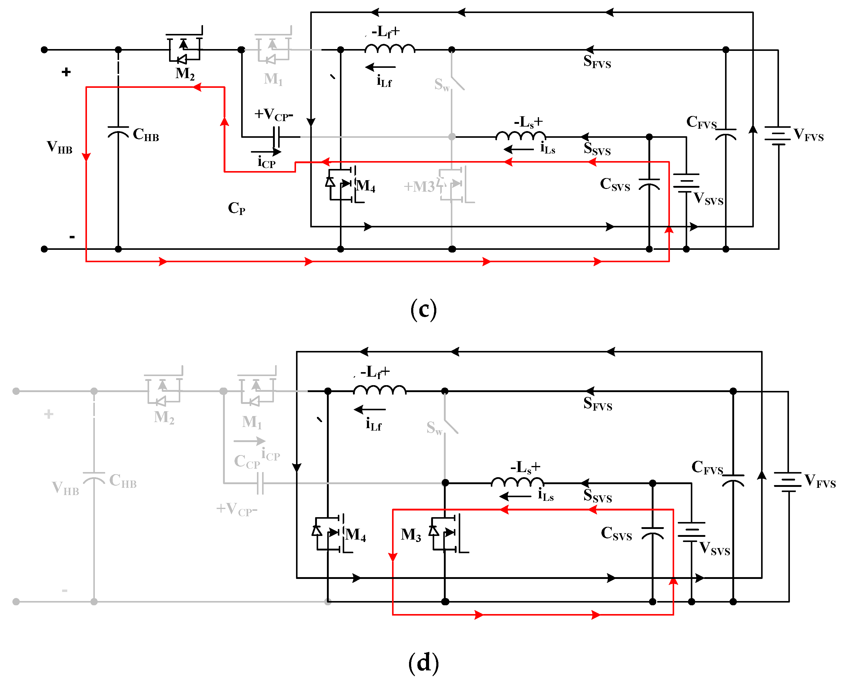
L f d i L f d t = V F V S
L s d i L s d t = V S V S
(c)
Stage 3 [t2 < t < t3]: The time interval at this stage is (1 − Dt)Ts. M1 and M3 switches are off, while M2 and M4 switches are on, as shown in Figure 4c. Characteristic equations in stage 3, in terms of voltage across the inductors Lf and Ls, are denoted by Equations (5) and (6):
L f d i L f d t = V F V S
L s d i L s d t = V C P + V S V S V H B
(d)
Stage 4 [t3 < t < t4]: Time interval at this stage is (Dt − 0.5)Ts. M3 and M4 switches are on, while the M1 and M2 switches are off, as shown in Figure 4d. Characteristic equations in stage 4, in terms of voltage across the inductors Lf and Ls, are denoted by Equations (7) and (8):
L f d i L f d t = V F V S
L s d i L s d t = V S V S

2.2. Regenerative Mode at High Voltage

In regenerative mode, the motor’s kinetic energy is returned to the voltage sources. Regeneration energy can be more than the battery’s storage capability, wherein the additional energy will be used to charge the storage devices. On the higher side, active switching regulates the current through the inductors, i.e., M3 and M4 switches with 180° phase shift angle. However, the lower side switches- M1 and M2, act as synchronous rectifiers, increasing the converter’s conversion performance. This can be observed in Figure 5a.
The duty ratio of the energy-regenerating mode for DC-bus high-voltage steady-state waveforms is less than 50%. Their four circuit stages are illustrated through Figure 6a–d. The stage-wise operation is explained in detail below:
(a)
Stage 1 [t0 < t < t1]: This stage is indicated in Figure 6a. Time interval is DtTs. Switches M1 and M3 are turned on, whereas switches M2 and M4 are turned off. Voltage across the main inductor, Lm, drops linearly from its original value. It is represented by the differential between the charge pump voltage, VCP and the lower side voltage, VFVS. An auxiliary inductor, La is charged by the energy source VAVS. Voltage across the auxiliary inductor, La increases linearly. Voltage across the inductors Lf and Lm in stage 1 is denoted by:
L f d i L f d t = V F V S V C P
L s d i L s d t = V S V S
(b)
Stage 2 [t1 < t < t2]: Time interval in this stage is (0.5 − Dt)Ts. M3 and M4 switches are ON, while M1 and M2 switches are OFF, as shown in Figure 6b. Positive lower side voltages VMVS and VAVS are located between the first and second inductors, respectively. These inductor currents increase linearly. Under stage 2, the voltages between the inductors Lf and Ls are indicated by:
L f d i L f d t = V F V S
L s d i L s d t = V S V S
(c)
Stage 3 [t2 < t < t3]: Time interval is DtTs at this stage. Switches M1 and M3 are off. M2 and M4 switches are on, as shown in Figure 6c. The differential between the lower side voltages VFVS and the charge pump voltages VCP indicates the voltage across the main inductor Lf, and the lower side voltage VSVS. Its level is negative. Under stage 3, the voltages across the inductors Lf and Ls are denoted by:
L f d i L f d t = V F V S
L s d i L s d t = V S V S + V C B V H B
(d)
Stage 4 [t3 < t < t4]: Time interval at this stage is (0.5 − Dt)Ts. M3 and M4 switches are on, while the M1 and M2 switches are off, as shown in Figure 6d. Under stage 4, the voltage across the inductors Lf and Ls is denoted by:
L f d i L f d t = V F V S
L s d i L s d t = V S V S

2.3. Buck/Boost Mode with Dual Low Voltage Sources

In this mode, energy stored in the first voltage source is transferred energy to the second voltage source and vice versa, as we can observe in Figure 7a.
If the duty cycle of active switch Sw is controlled, as shown in Figure 8, it operates as a buck converter. It is because power flows from first voltage source to second voltage source. This depicts the circuit stages in buck mode of the planned BDC with dual low-voltage sources. If the duty cycle of switch M3 is regulated, the converter will operate in boost mode, as shown in Figure 9. It depicts the boost mode of the expected BDC circuit stages for the dual low-voltage sources. In this mode, power transfers from the second voltage source to the first voltage source.

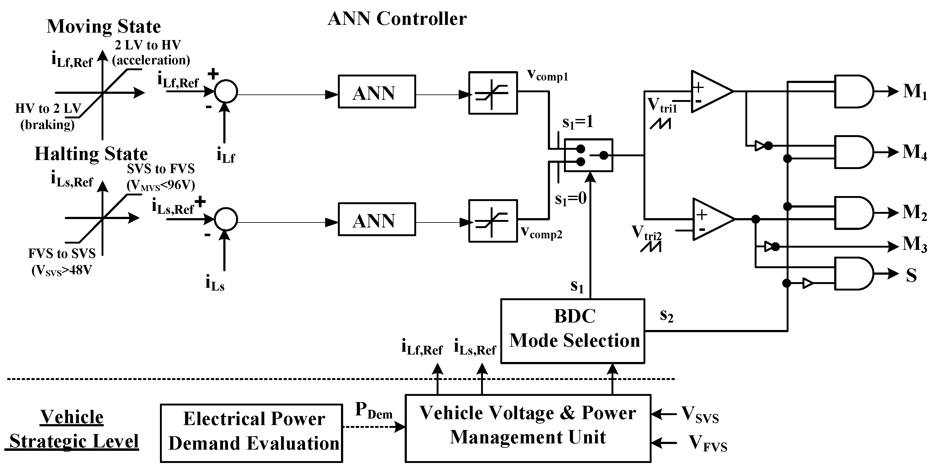
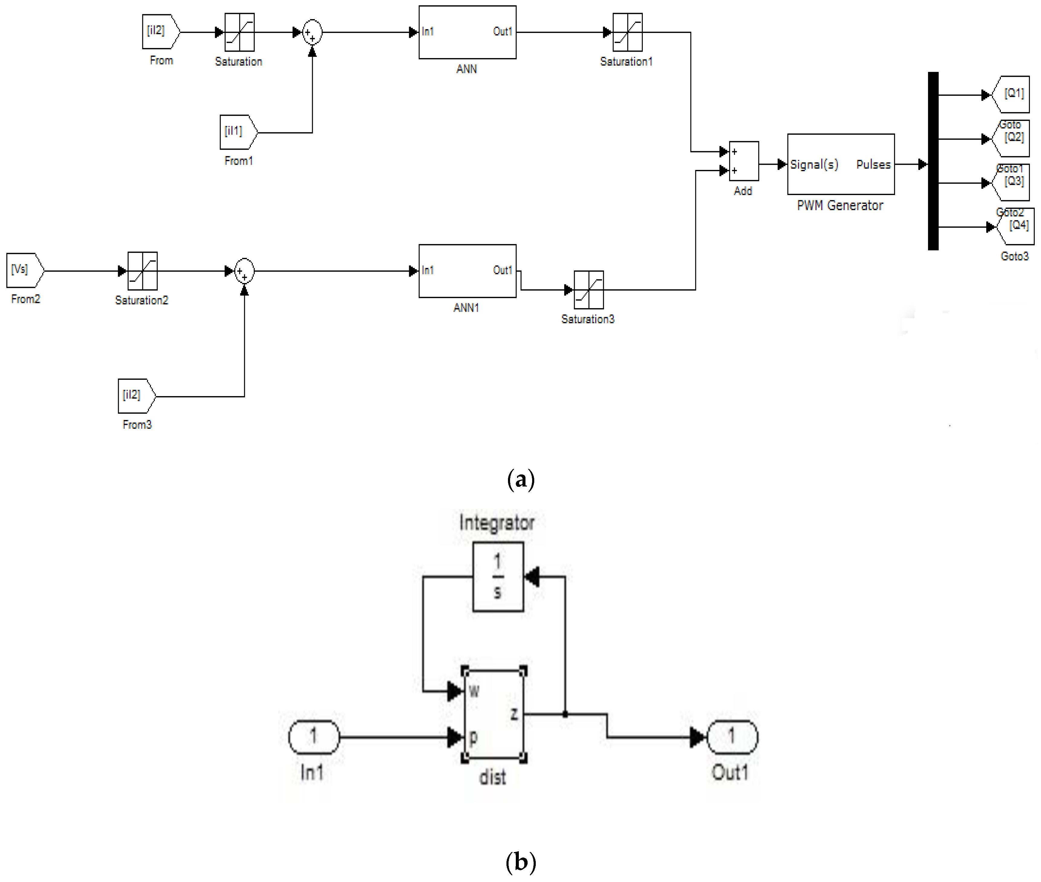
3. Converter Control

Figure 10 shows the block diagram of the feedback-loop control technique, which comprises choosing a vehicle strategic level and mode of BDC to govern pulse width modulation switching schemes. Several operating modes of the BDC controller are depicted in Figure 11. As indicated in the closed loop controller architecture, the vehicular key level necessitates power demand (PDem), vehicle voltage, and power management units. They serve as input signals to BDC mode selection. Overall results of the power management units improve the utilization of voltage sources to meet the power train’s power demand, satisfying the requirements of the driver. In Figure 10 inductor currents, i L m and i L a are calculated and then compared to the reference converter currents. In this mode of controller operation, different driving states of power demand (PDem) and voltage sources (VFVS, VSVS) are used to determine the vehicle condition. Then, using an artificial neural network, appropriate current references- i L m R e f or i L a R e f are selected to control the power switches- Sw, M1, M2, M3 and M4. Pulse width modulation (PWM) switching methods transform the duty cycle into regulated gate signals for the active switches (Sw, M1, M4), and the BDC controller’s switch selectors (S1, S2).
i L m R e f is used to regulate the power flowing from 2 LV to HV or HV to 2 LV on dual low and high DC-buses voltage sources, whereas i L a R e f is also used to regulate the power flowing from the first to the second voltage source and vice versa (i.e., from VFVS to VSVS or from VSVS to VFVS).
When the vehicle is in moving state (PDem > 0), the control loop s = 1 in the controller iLm is activated, and it operates in two modes: accelerating and braking, as seen in the controlled switches in Table 1. If both conditions are not met, it returns to the reassign mode to operate the very next perception of switching mode. Furthermore, while the vehicle is in a halting condition (PDem < 0), the control loop s1 = 0 in the controller iLa will work in two modes, buck and boost, as illustrated in the controlled switches in Table 1. Voltages VFVS (96 V) and VSVS (48 V) are used to perceive mode change in this halting condition. During boost mode, i.e., when VFVS is less than 96 V and i L a R e f > 0 , power flows from the VSVS to the VFVS. During buck mode, i.e., when VFVS is less than 46 V and i L a R e f < 0 , power flows from VFVS to the VSVS. If neither of these conditions is met, the system reverts to the reassign mode, which is used to process the next perception of mode switching. Figure 12a,b show the various steps in modeling of an ANN controller implemented in this research work.

4. Discussion

A simulation model is provided in Figure 2 to validate the feasibility and performance of the BDC converter topology with dual battery. It was modelled in MATLAB/Simulink and the system’s four operation modes are investigated. Table 2 contains the system parameters.
A traction motor was powered by both sources, which increased the two input voltages, as shown in Figure 14. As a result, the DC-bus voltage VHB of 430 V was influenced by both sources. Performance in powering mode is illustrated in Figure 13 and Figure 14 with performance in regenerative mode shown in Figure 15.
Figure 13 show the gate pulses delivered to switches M1, M2, M3, and M4, in powering mode and regenerative mode, respectively. Inductor currents i L F and i L S are shown in Figure 14 and Figure 15, respectively. Figure 15 illustrates inductor current and output voltage in DC-bus energy-regenerative mode at high voltage.
Power transfer from the DC-bus towards the main and auxiliary voltage sources is shown in Figure 15. Input power flows in the opposite direction, as clearly postulated from the inductor currents i L F and i L S . On the lower side output voltages, VFVS and VSVS were about 96 V and 48 V, respectively.
Using dual low-voltage sources, simulated waveforms–gate signals, inductor currents and output voltages during buck and boost modes are shown in Figure 16 and Figure 17, respectively. In Figure 16, the currents in the inductor are inverted from those in Figure 17. This validates bidirectional power to flow between the second and first voltage sources. Finally, all of the simulation results are consistent with the stable-state prediction study. Waveforms of regulated current step variations for the conceptual design in the high voltage energy-regenerative mode and the dual low-voltage sources-powering mode are displayed in Figure 18 and Figure 19, respectively. In order to transmit energy from the dual lower-side sources to the higher-side DC-bus, the current in the inductor i L F and the higher-side current i H B were adjusted, as illustrated in Figure 18. Negative current output waveforms are indicated in Figure 19. The power flow was effectively inverted.
Figure 20 and Figure 21 show the waveforms of regulated current step variations for the conceptual model for the dual low-voltage sources buck and boost modes, respectively. The higher-side current i F V S and the inductor current i L S were altered to distribute energy between two low-voltage source currents. Inductor current i L S and the first voltage source current i F V S were controlled to transmit the power from the second voltage source to the first voltage source. In Figure 20, the output waveforms of negative current were effectively inverted, and in Figure 21, the power flow was effectively inverted.

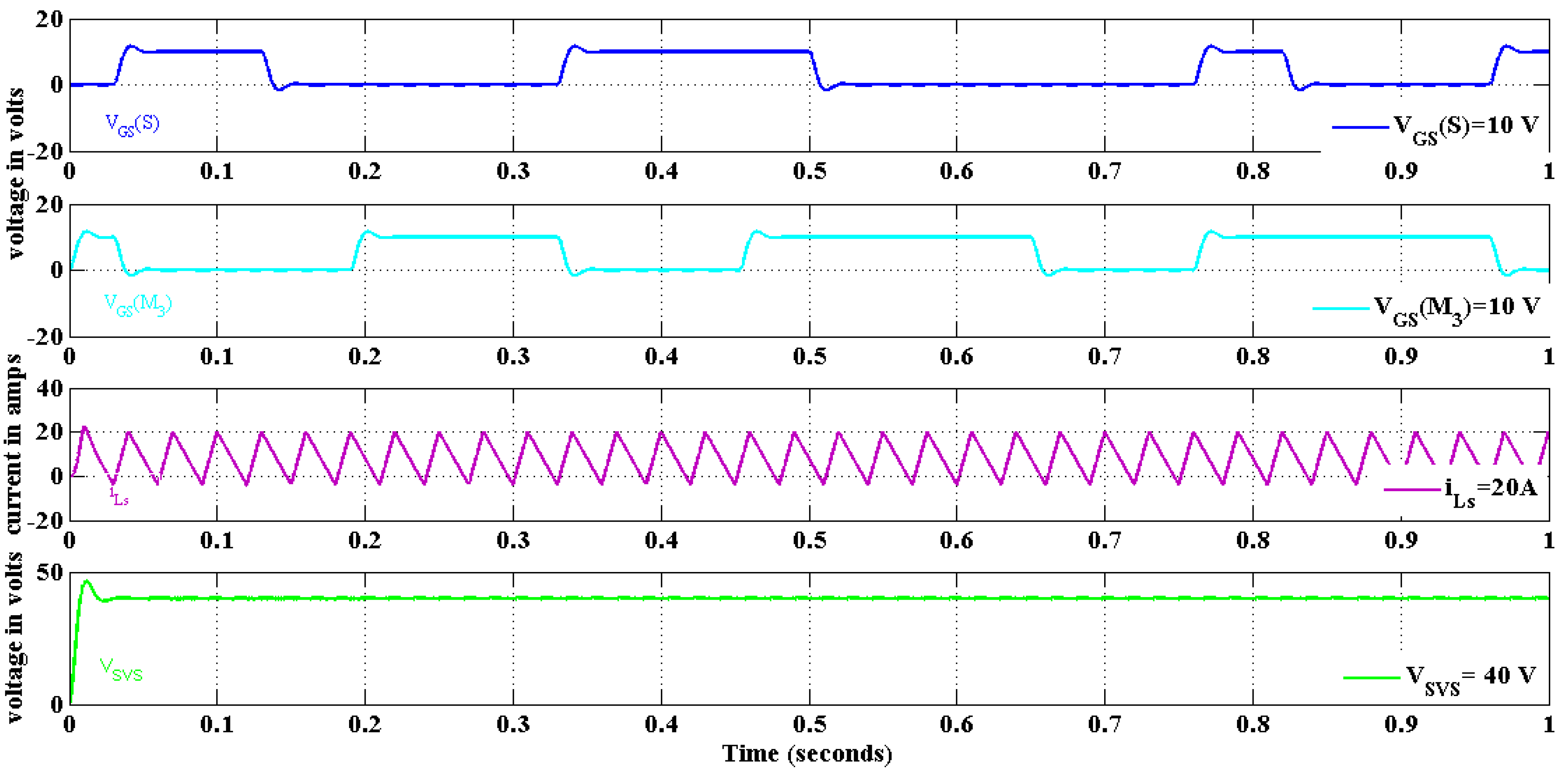
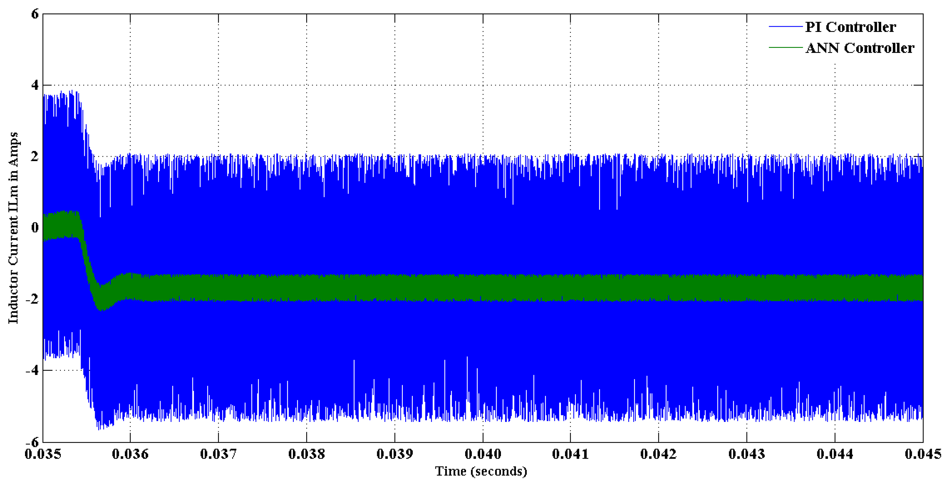
Comparison of PI and ANN Controller Output Waveforms

Figure 22 shows a comparison of output voltage in power sharing mode at low voltage, while Figure 23 illustrates a comparison of output voltage in DC-bus high-voltage regenerative mode. Figure 24 and Figure 25 show controlled current step variation in inductor currents in buck and boost modes of operation.
Comparative analysis highlights that an ANN controller has a significantly faster rising time and processing speed than the PI controller, and the ANN controller has reduced ripple content in the current signal.

5. Conclusions

Dual battery voltage sources were integrated with higher-voltage DC-buses of varying voltage levels using the BDC architecture. Various forms of power transfer were used to discuss the circuit architecture and operational concepts of the BDC. To thoroughly investigate the energy flow between the first and the second voltage sources under the strong variations in voltage levels, regenerative mode, powering mode and inductor currents, a controlled DC–DC voltage static converter with a neural network controller was developed and implemented using MATLAB/Simulink. This controller was simpler to implement, with a limited number of tests carried out in MATLAB. To corroborate the robustness of the proposed converter with the neural network controller, strong variations in voltage levels of the voltage sources, regenerative and powering modes were applied to the hybrid electric vehicle. The simulation results show the effectiveness and the robustness of both the proposed controller and converter to control the power flow between various voltage sources and minimize the current ripples between DC-bus and voltage sources. As a result, inductor current oscillations were reduced.
In future work, efficacy of the proposed BDC should be assessed in a realistic EV domain, employing advanced controllers. Finally, as an obligatory experimentation to this study, the practical implementation of the proposed DC–DC converter should be performed in future research.

Author Contributions

R.S.R.S.: Conceptualization, supervision, investigation, methodology, analysis; K.D.K.: writing—original draft preparation, visualization; B.A.: funding acquisition, data curation; M.A.: resources, project administration. All authors have read and agreed to the published version of the manuscript.

Funding

This research was funded from Taif University Researchers Supporting Project Number (TURSP-2020/278), Taif University, Taif, Saudi Arabia.

Data Availability Statement

Not applicable.

Acknowledgments

The authors would like to acknowledge the financial support received from Taif University Researchers Supporting Project Number (TURSP-2020/278), Taif University, Taif, Saudi Arabia.

Conflicts of Interest

The authors declare that they have no known competing financial interest or personal relationships that could have appeared to influence the work reported in this paper.

Notations

Notations used throughout the paper are stated below:
VHBDC-bus high voltage
VFVS, VSVSDual low-voltage sources
CCPCharge pump capacitor
M1, M2, M3, M4Four active switches
Lf, LsPhase inductors
iLfMain phase inductor current
iLsAuxiliary phase inductor current
SW, SFVS, SSVSThree bidirectional switches
iCPCharge pump current
CFVSFirst voltage source capacitor
CSVSSecond voltage source capacitor

References

  1. Ni, L. Energy Storage and Management for a Small Series Plug-in Hybrid Electric Vehicle. Ph.D. Thesis, University of Nebraska, Lincoln, NE, USA, 2010. [Google Scholar]
  2. Bethoux, O. Hydrogen Fuel Cell Road Vehicles: State of the Art and Perspectives. Energies 2020, 13, 5843. [Google Scholar] [CrossRef]
  3. Sanguesa, J.A.; Torres-Sanz, V.; Garrido, P.; Martinez, F.J.; Marquez-Barja, J.M. A Review on Electric Vehicles: Technologies and Challenges. Smart Cities 2021, 4, 372–404. [Google Scholar] [CrossRef]
  4. Chan, C.C. Electric, hybrid, and fuel-cell vehicles: Architectures and modeling. IEEE Trans. Veh. Technol. 2010, 59, 589–598. [Google Scholar] [CrossRef]
  5. Donatantonio, F.; Ferrara, A.; Polverino, P.; Arsie, I.; Pianese, C. Novel Approaches for Energy Management Strategies of Hybrid Electric Vehicles and Comparison with Conventional Solutions. Energies 2022, 15, 1972. [Google Scholar] [CrossRef]
  6. Thounthong, P.; Chunkag, V.; Sethakul, P.; Davat, B.; Hinaje, M. Comparative study of fuel-cell vehicle hybridization with battery or supercapacitor storage device. IEEE Trans. Veh. Technol. 2009, 58, 3892–3904. [Google Scholar] [CrossRef]
  7. Rizzo, G.; Tiano, F.A.; Mariani, V.; Marino, M. Optimal Modulation of Regenerative Braking in Through-The-Road Hybridized Vehicles. Energies 2021, 14, 6835. [Google Scholar] [CrossRef]
  8. Al-Adsani, A.S.; Jarushi, A.M.; Beik, O. ICE/HPM generator range extender for a series hybrid EV powertrain. IET Electr. Syst. Transp. 2020, 10, 96–104. [Google Scholar] [CrossRef]
  9. Rajashekara, K. Present status and future trends in electric vehicle propulsion technologies. IEEE J. Emerg. Sel. Top. Power Electron. 2013, 1, 3–10. [Google Scholar] [CrossRef]
  10. Aouichak, I.; Jacques, S.; Bissey, S.; Reymond, C.; Besson, T.; Le Bunetel, J.-C. A Bidirectional Grid-Connected DC–AC Converter for Autonomous and Intelligent Electricity Storage in the Residential Sector. Energies 2022, 15, 1194. [Google Scholar] [CrossRef]
  11. Daviran Keshavarzi, M.; Ali, M.H. A Novel Bidirectional DC-DC Converter for Dynamic Performance Enhancement of Hybrid AC/DC Microgrid. Electronics 2020, 9, 1653. [Google Scholar] [CrossRef]
  12. Choi, Y.; Chang, N.; Kim, T. DC–DC Converter-Aware Power Management for Low-Power Embedded Systems. IEEE Trans. Comput. -Aided Des. Integr. Circuits Syst. 2007, 26, 1367–1381. [Google Scholar] [CrossRef]
  13. DErb, C.; Onar, O.C.; Khaligh, A. Bi-directional charging topologies for plug-in hybrid electric vehicles. In Proceedings of the 2010 Twenty-Fifth Annual IEEE Applied Power Electronics Conference and Exposition (APEC), Palm Springs, CA, USA, 21–25 February 2010; pp. 2066–2072. [Google Scholar]
  14. Du, Y.; Lukic, S.; Jacobson, B.; Huang, A. Review of high power isolated bi-directional DC–DC converters for PHEV/EV DC charging infrastructure. In Proceedings of the 2011 IEEE Energy Conversion Congress and Exposition, Phoenix, AZ, USA, 17–22 September 2011; pp. 553–560. [Google Scholar]
  15. Zhou, M.; Fu, J.; Wu, X.; Yang, M.; Zhang, Z. A Non-isolated High-gain DC/DC Converter Suitable for Fuel Cell Vehicles. J. Electr. Eng. Technol. 2021, 17, 271–282. [Google Scholar] [CrossRef]
  16. Choi, Y.G.; Lee, S.W.; Lee, H.S.; Lee, S.C.; Kang, B. Increase in Power Conversion Efficiency of Bidirectional DC-DC Converter Using 1:1 Transformer and Pulse-Frequency Modulation Control. IEEE Trans. Power Electron. 2018, 33, 10539–10549. [Google Scholar] [CrossRef]
  17. Lin, C.; Yang, L.; Wu, G.W. Study of a non-isolated bidirectional DC-DC converter. IET Power Electron. 2012, 6, 30–37. [Google Scholar] [CrossRef]
  18. Deepika, K.K.; Kumar, J.; Varma, P.; Sura, S.; Sankar, R. Design of Back-to-Back Converter Interface for Electric Spring in a Distribution System. Front. Energy Res. 2022, 10, 765899. [Google Scholar] [CrossRef]
  19. Fasugba, M.A.; Krein, P.T. Cost benefits and vehicle-to-grid regulation services of unidirectional charging of electric vehicles. In Proceedings of the 2011 IEEE Energy Conversion Congress and Exposition, Phoenix, AZ, USA, 17–22 September 2011; pp. 827–834. [Google Scholar]
  20. Choe, G.-Y.; Kim, J.-S.; Lee, B.-K.; Won, C.-Y.; Lee, T.-W. A bidirectional battery charger for electric vehicles using photovoltaic PCS systems. In Proceedings of the 2010 IEEE Vehicle Power and Propulsion Conference, Lille, France, 1–3 September 2010; pp. 1–6. [Google Scholar]
  21. Wang, J.; Wang, B.; Zhang, L.; Wang, J.; Shchurov, N.I.; Malozyomov, B.V. Malozyomov, Review of Bidirectional DC-DC Converter Topologies for Hybrid Energy Storage System of New Energy Vehicles. Green Energy Intell. Transp. 2022, 1, 100010. [Google Scholar] [CrossRef]
  22. Lai, C.-M.; Lin, Y.-C.; Lee, D. Study and implementation of a two-phase interleaved bidirectional DC/DC converter for vehicle and dc-microgrid systems. Energies 2015, 8, 9969–9991. [Google Scholar] [CrossRef]
  23. Lai, C.-M. Development of a novel bidirectional DC/DC converter topology with high voltage conversion ratio for electric vehicles and DC-microgrids. Energies 2016, 9, 410. [Google Scholar] [CrossRef] [Green Version]
  24. Haihua, Z.; Khambadkone, A.M. Hybrid modulation for dual active bridge bi-directional converter with extended power range for ultracapacitor application. In Proceedings of the 2008 IEEE Industry Applications Society Annual Meeting, Edmonton, AB, Canada, 5–9 October 2008; pp. 1–8. [Google Scholar]
  25. Lai, C.M.; Lin, Y.J.; Hsieh, M.H.; Li, J.T. A newly-designed multiport bidirectional power converter with battery/supercapacitor for hybrid electric/fuel-cell vehicle system. In Proceedings of the 2016 IEEE Transportation Electrification Conference and Expo, Asia-Pacific (ITEC Asia-Pacific), Busan, Korea, 1–4 June 2016; pp. 163–166. [Google Scholar] [CrossRef]
  26. Lai, C.M.; Cheng, Y.H.; Hsieh, M.H.; Lin, Y.C. Development of a Bidirectional DC/DC Converter With Dual-Battery Energy Storage for Hybrid Electric Vehicle System. IEEE Trans. Veh. Technol. 2018, 67, 1036–1052. [Google Scholar] [CrossRef]
  27. Kang, H.S.; Kim, S.M.; Bak, Y.; Lee, K.B. A controller design for a stability improvement of an integrated charging system in hybrid electric vehicle. IFAC 2019, 52, 141–146. [Google Scholar] [CrossRef]
  28. Barhoumi, E.M.; Ben Belgacem, I.; Khiareddine, A.; Zghaibeh, M.; Tlili, I. A Neural Network-Based Four Phases Interleaved Boost Converter for Fuel Cell System Applications. Energies 2018, 11, 3423. [Google Scholar] [CrossRef] [Green Version]
  29. Moreno, J.; Ortúzar, M.E.; Dixon, J.W. Energy-management system for a hybrid electric vehicle, using ultracapacitors and neural networks. IEEE Trans. Ind. Electron. 2006, 53, 614–623. [Google Scholar] [CrossRef]
  30. Li, Z.; Pang, J.; Xu, C.; Zhang, C. Electric vehicle charging system pressure control based on fuzzy neural network PID control. In Proceedings of the 2021 IEEE Conference on Telecommunications, Optics and Computer Science (TOCS), Shenyang, China, 10–11 December 2021; pp. 873–877. [Google Scholar] [CrossRef]
  31. Wang, P.; Li, X. Estimation and Prediction on State of Health of Electric Vehicle Battery Based on BP Neural Network. In Proceedings of the 2021 IEEE 3rd International Conference on Frontiers Technology of Information and Computer (ICFTIC), Greenville, SC, USA, 12–14 November 2021; pp. 729–732. [Google Scholar] [CrossRef]
  32. Reddy, K.J.; Sudhakar, N. ANFIS-MPPT control algorithm for a PEMFC system used in electric vehicle applications. Int. J. Hydrog. Energy 2019, 44, 15355–15369. [Google Scholar] [CrossRef]
  33. Wang, B.; Wang, C.; Hu, Q.; Ma, G.; Zhou, J. Adaptive sliding mode control with enhanced optimal reaching law for boost converter based hybrid power sources in electric vehicles. J. Power Electron. 2019, 19, 549–559. [Google Scholar]
  34. Liu, K.; Hu, X.; Yang, Z.; Xie, Y.; Feng, S. Lithium-ion battery charging management considering economic costs of electrical energy loss and battery degradation. Energy Convers. Manag. 2019, 195, 167–179. [Google Scholar] [CrossRef]
Figure 1. Basic block diagram for a hybrid electric vehicle (HEV) power system.
Electronics 11 03564 g001
Figure 2. Dual-battery energy storage in BDC architecture.
Electronics 11 03564 g002
Figure 3. (a) Schematic Diagram. (b) Waveforms of BDC’s dual low-voltage sources powering mode.
Electronics 11 03564 g003aElectronics 11 03564 g003b
Figure 4. Circuit stages of BDC’s dual low-voltage sources powering mode.
Electronics 11 03564 g004aElectronics 11 03564 g004b
Figure 5. (a) Schematic Diagram. (b) Waveforms of BDC’s DC-bus high voltage energy-regenerative mode.
Electronics 11 03564 g005aElectronics 11 03564 g005b
Figure 6. Circuit stages in regenerating mode at high voltage.
Electronics 11 03564 g006aElectronics 11 03564 g006b
Figure 7. BDC’s dual low-voltage sources buck/boost mode. (a) Schematic Diagram. (b) Buck-mode stable-state waveforms. (c) Boost-mode stable-state waveforms.
Electronics 11 03564 g007aElectronics 11 03564 g007b
Figure 8. (a) Stage 1 (b) Stage 2.
Electronics 11 03564 g008
Figure 9. (a) Stage 1. (b) Stage 2.
Electronics 11 03564 g009
Figure 10. Block diagram for feedback loop control technique.
Electronics 11 03564 g010
Figure 11. Flowchart for the planned BDC’s multiple working modes.
Electronics 11 03564 g011
Figure 12. (a). Switching mechanism of ANN controller. (b). Euclidean distance ANN method.
Electronics 11 03564 g012
Figure 13. Gate signals in powering mode.
Electronics 11 03564 g013
Figure 14. Inductor current wave form in powering mode.
Electronics 11 03564 g014
Figure 15. Output voltages and inductor currents in regenerative mode.
Electronics 11 03564 g015
Figure 16. Gate signals, output voltage and inductor currents for buck mode.
Electronics 11 03564 g016
Figure 17. Gate signals, output voltage and inductor currents for boost mode.
Electronics 11 03564 g017
Figure 18. Regulated current step variations in inductor currents at dual low voltage sources.
Electronics 11 03564 g018
Figure 19. Regulated current step variations in inductor currents at high bus voltage.
Electronics 11 03564 g019
Figure 20. Regulated current step variations in inductor currents at buck mode.
Electronics 11 03564 g020
Figure 21. Regulated current step variations in inductor currents in boost mode.
Electronics 11 03564 g021
Figure 22. Regulated current step variations in inductor currents at dual low voltage sources.
Electronics 11 03564 g022
Figure 23. Regulated current step variations in inductor currents at high bus voltage.
Electronics 11 03564 g023
Figure 24. Regulated current step variations in inductor currents during boost mode.
Electronics 11 03564 g024
Figure 25. Regulated current step variations in inductor currents during buck mode.
Electronics 11 03564 g025
Table 1. Conduction status of devices for various operation modes.
Operation ModesSwitches in ONSwitches in OFFControl SwitchesSynchronous Rectifiers (SR)
Dual low-voltage sources powering mode (Accelerating, x1 = 1, x2 = 1)SFVS,SSVSSwM3,M4M1,M2
DC-bus energy-regenerative mode at high-voltage (Braking, x1 = 1, x2 = 1)SFVS,SSVSSwM1,M2M3,M4
Dual low-voltage sources buck mode (FVS to SVS, x1 = 0, x2 = 0)SFVS,SSVSM1,M2,M4SwM3
Dual low-voltage sources boost mode (FVS to SVS, x1 = 0, x2 = 0)SFVS,SSVSM1,M2,M4M3Sw
Table 2. Parameters and ratings of the HEV system.
ParametersRatings
InductorsLf = Ls = 250 µH
High-side capacitorCHB = 1880 µF
Low-side capacitorCFVS = CSVS = 400 µF
Charge-pump capacitorCCP = 10 µF
ESR of inductanceRLf = RLs = RL = 50 mꭥ
ESR of capacitanceRCB = 20 mꭥ,RFVS = RSVS = 50 mꭥ
Line resistanceRFVS = 12 mꭥ, RSVS = 6 mꭥ
First voltage sourceFVS = 96 V
Second voltage sourceSVS = 40 V
Publisher’s Note: MDPI stays neutral with regard to jurisdictional claims in published maps and institutional affiliations.

