1. Introduction
According to the 2022 IRF (International Federation of Robotics) report, based on 2021 numbers, the still dominant industries in terms of robot applications are electrotechnical/electronics (137,000 robots were installed in production), automotive (119,000 units) and engineering ones (64,000 units). Based on the 2020 IRF report about the use of industrial robots [
1], the use of robots in machining, deburring, and grinding is growing significantly. Due to the aforementioned facts, one of the challenges of robotics is to increase the accuracy and repeatability of industrial robots. This will make it possible to perform advanced machining or assembly tasks. In certain areas, it will be possible to replace costly CNC machines. Methods to improve the accuracy and repeatability parameters of robots are numerous. Improving stiffness, modifying control systems, or using external systems for measuring and path correction. Using laser trackers is one way to accurately measure TCP orientation position and online correction for industrial robots. A laser tracker is a tool that enables various types of geometric measurements in three-dimensional space. It can be used for automated position control as well as, e.g., for 3D scanning of objects. Its most important elements are the laser interferometer and the absolute rangefinder. Due to their accuracy, robotics trackers are used in testing the accuracy and repeatability of manipulating robots and for their calibration [
2,
3,
4]. Laser trackers in robotic measurements are used for a variety of applications. In the paper [
5], the authors present an innovative methodology for measuring the susceptibility of articulated serial robots, and the laser tracker is used to measure the system’s response.
In paper [
6], the laser tracker was used to measure the deflection of the robot end effector during comparative tests and optimization of the robot position using static and dynamic stiffness models for various milling scenarios.
The authors of the papers [
7,
8] ponder how to increase the accuracy of industrial robots with the help of the Leica Absolute Tracker AT960 (Hexagon, Stockholm, Sweden). They propose new methods of calibrating robots with tools in their workplace. These methods improve positioning accuracy by compensating for the identified parameters. The accuracy of the robots, along with the reduction in calibration time, are key factors in the success of robotic production systems.
In paper [
9], the authors discuss assembly operations in the aviation industry, which are time-consuming and require high accuracy. They emphasize that robotic assembly is a good solution that increases productivity, but they point out that the poor accuracy of industrial robots limits their use. They propose to improve it by adding an accurate online 3D positioning system, which consists of the KEYENCE LJ-V7200 vision system (Keyence, Osaka, Japan) and the Leica AT-960 + T-Mac TMC-30B (Hexagon, Stockholm, Sweden) tracking system.
Paper [
10] investigated the ability of a laser tracker to measure the relative position and orientation between two mobile Stewart platforms simulating the movement of ships at sea. These ships are exposed to disturbance from waves and have cranes equipped with active compensation systems on board, which keep the cargo at a certain height from the seabed.
In paper [
11], a laser tracker was used to improve the accuracy of cable-driven parallel robots. Inaccuracies are caused by deviations in cable lengths caused by elongation, elasticity, or creep.
In paper [
12], the authors focus on modeling, measuring, and identifying the change in the kinematic chain of serial articulated industrial robots based on thermomechanical deformations caused by self-heating caused by drives. The assessment of the change in the positioning accuracy of the ABB IRB 1600 (ABB Ltd., Zürich, Switzerland) robot was carried out using a Leica AT960 laser tracker and a FLIR SC640 (FLIR, Wilsonville, OR, USA) thermal imaging camera.
The authors of the work [
13] used a laser tracker to improve the absolute accuracy of the ABB IRB 1600 industrial robot. They developed an advanced calibration model that significantly reduced position errors. Similar work was carried out by the authors of [
14], who focused on building calibration systems easily adaptable to each robot type. A computer system was built to develop and implement a calibration system. Subsequently, experimental trials were carried out using the IRB2000 robot, which resulted in a large accuracy improvement. Similar works on calibration and improvement of accuracy were carried out by researchers [
15,
16,
17,
18]. The use of trackers in robotics, however, often goes beyond accuracy testing and calibration. The subject of real-time tracker compensation is discussed in [
19,
20].
In paper [
19], the authors described the idea of compensation for production systems by using external metrological systems to compensate machine tools and robots in real-time. On the other hand, in the article [
20], they used direct feedback from the position and orientation of the end effector with the Leica laser tracker to develop an algorithm that allowed for moving along paths at a speed of 100 mm/s with an RMS of only 0.11 mm.
The compensation for errors in production processes in the aviation industry is the subject of article [
21]. The authors of that paper show a method of maintaining high accuracy of robot manipulation by continuously tracking the position and orientation of the mounted tool while minimizing errors. The study of parameters of industrial robots with the use of trackers during contact operations is the subject of [
22,
23]. In paper [
22], researchers evaluate the performance of robots during deburring, grinding, and cutting operations in terms of quasi-static path accuracy and repeatability. In article [
23], the authors investigate the modal properties of industrial robots during the milling process using a tracker. The applications of laser trackers in robotics mentioned so far concern manipulating industrial robots. In the segment of mobile robots, laser trackers are most often used for calibration or as a position verification tool. Paper [
24] presents a method of autonomous loading, transporting, and unloading large objects using a non-holonomic mobile manipulator. The Faro Vantage S6 laser tracker was used to calibrate and verify the operation of the target vision system.
A tracker for calibrating a six-legged walking robot with an integrated parallel manipulator was used in [
25]. The authors of this work, after applying the proposed tracker method for validation, identified the kinematic parameters of the entire robot, and the accuracy of the movement of each leg and manipulator was significantly improved. In [
26], a laser tracker was used to track the trajectory of a mobile robot based on linkage suspension. Using a tracker allowed for the trajectory of the physical prototype of a mobile robot to be registered and analyzed.
The subject of applications related to recording and sharing data from trackers is discussed by the authors less often than using them to measure accuracy and repeatability. Applications are most often created by manufacturers of individual trackers and are used for metrology. Proprietary software for data sharing and communication with laser trackers is often created. An example of such a solution was shown by the authors of [
27]. They developed a real-time control system for the position and orientation of industrial robots using a laser tracker. Via the developed real-time interface, position data is acquired in millisecond cycles and is used to calculate the current errors of the robot path. The EtherCAT bus and a dedicated software solution were used for data transmission between the Leica tracker and the robot controller. Similar research work was presented in articles [
28,
29]. In these works, the authors show the software they developed for communication with a laser tracker, along with examples of applications. The paper [
29] shows the most advanced example of the functioning of an application working behind a PC and communicating with a robot via KUKA RSI (robot sensor interface). The software runs on a Windows PC and supports communication with the laser tracker via Ethernet using the FARO SDK for the laser tracker.
As for other applications of laser trackers, in the paper [
30], a laser scanner, alongside a manipulator and a 3D scanner, was used as part of a system for determining the position of small assembly points on large-scale components. The authors indicate that the developed method of a large-scale 3D measurement reduces the maximum and average calibration error of the measurement system by about 55% at a measurement radius of 7 m. An analogous use of trackers is presented in the paper [
31]. The paper describes the use of trackers for particle accelerators. Due to their mobility and accuracy, they are used to determine the position of magnets, which is a critical part of its construction and requires tolerances of millimeters at distances of tens of meters. The paper [
32] describes the use of multiple trackers forming a trilateration network to improve the accuracy of measuring the flatness of the surface of a 5 m diameter ring. The effect of the positioning of the trackers, their number in the network, and differences in the height of the measurement head on the accuracy of po-measurement were presented. In the case of measuring flatness with two trackers placed in the center of the ring, whose height difference is 1 m, the measurement accuracy is ±6 μm.
Laser trackers are used in the construction of devices that require very high-precision manufacturing. Papers [
33] discuss the use of a tracker for the precise positioning of particle accelerator systems. To increase precision, several trackers can be combined into a single system, as shown in the example of positioning a high-energy photon source High Energy Photon Source (HEPS) system [
34].
Laser trackers can be used not only to validate the accuracy of the manipulators themselves. They are also used to determine the accuracy of various calibration instruments interfacing with industrial robots, such as the case described in the paper [
35], where the authors checked the accuracy of a robot’s TCP automatic self-calibration instrument.
Another interesting use of a laser tracker is the work [
36] where the authors proposed using the tracker to measure the position of the drill stem of a drilling rig. By measuring the ground part, the authors could estimate the shape of the hole drilled by the rig.
The authors of article [
37] developed a method of using a laser tracker to program paths of industrial robots. While working on this method, it turned out that it would be useful to develop a universal application that makes tracker data available to various types of robots. In the solution presented there, the data with the positions measured by the tracker was saved on a PC and then loaded from this computer by the robot controller. The presented solution was not universal and was cumbersome to use. In connection with the problem described, work was started on the development of an own application that provides data from the tracker. Software for manipulating robots, mobile robots, and data transferring to popular software used, among others, in robotics, namely the Matlab-Simulink package, was designed and developed. The idea behind the tracker and the developed software will be discussed later. Examples of its applications will also be presented.
2. Characteristics of the Tracker and the Method of Recording and Sharing the Measured Parameters
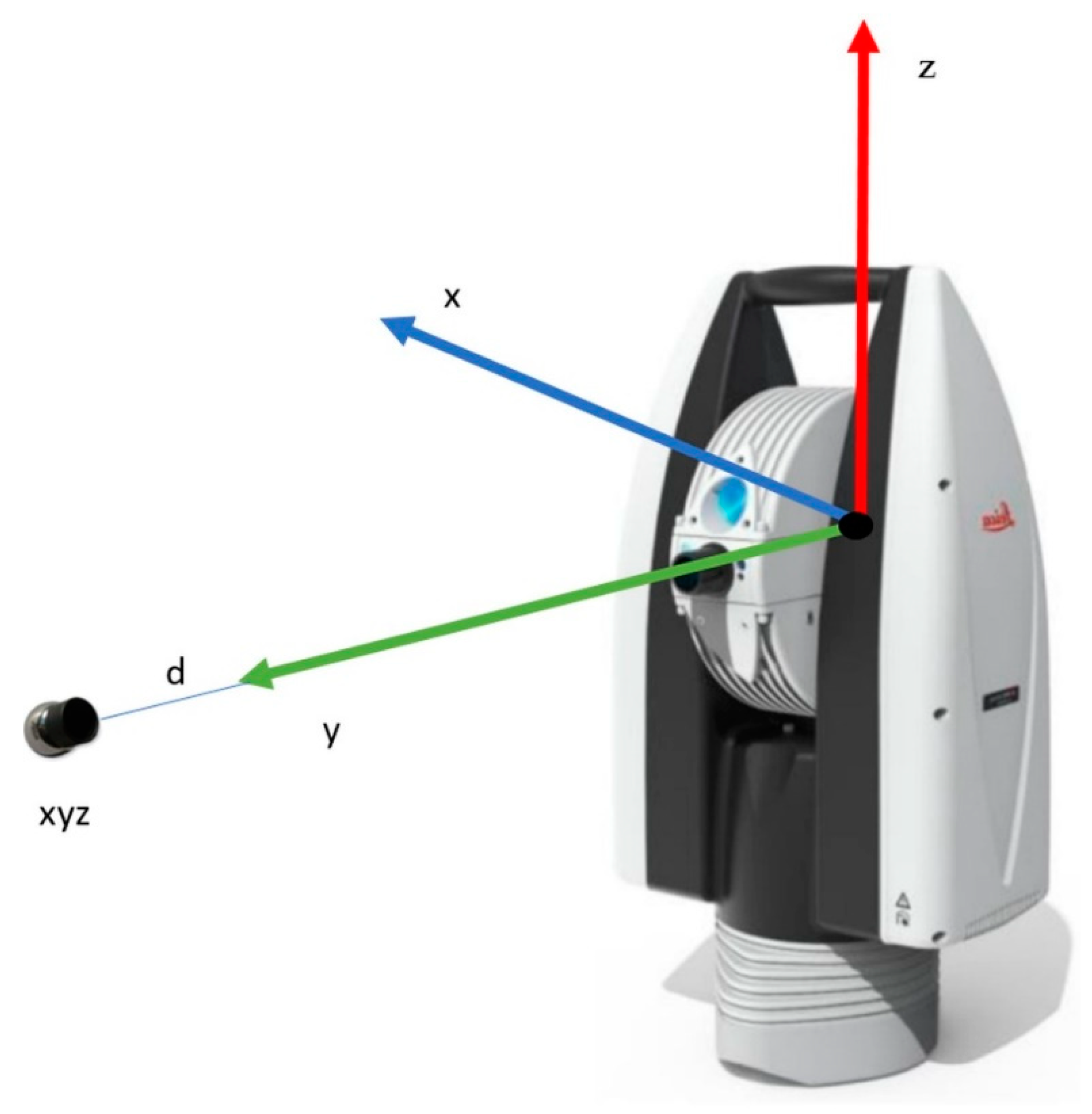
Measuring with a laser tracker is often considered a coordinate measurement method. It allows for precise measurements of the position of a selected point in three directions simultaneously. These devices are used in geodesy, scanning large-size objects in 3D, and automated control in industry. When using a laser tracker (
Figure 1), it is necessary to install a mirror reflecting the laser beam, the so-called sphere-mounted retroreflector (SMR).
Research work on the own software was carried out with the use of the Leica AT960 absolute laser tracker. It is a very accurate device that specifies its accuracy as a maximum permissible error (MPE). The maximum permissible error (MPE) is defined in the ISO 10360-10: 2016 standard as the highest value of the measurement error allowed in the specification for a given measurement.
Table 1 shows the tracker specification according to ISO 10360-10: 2016, Annex E.
The described tracker and its equipment are part of the industrial robotics laboratory of the Department of Applied Mechanics, Rzeszow University of Technology. The tracker and robots located in the laboratory are used to design and program stations dedicated to aviation industry needs. The tracker was used in the station’s design to control the outlet guide vanes (OGV) described in [
38]. Tracker measurements were useful when designing a module for geometrical measurements of jet engine blades described in [
39]. Geometric measurements taken with a tracker turned out to be useful during the development of digital twins for the purposes of training with the use of virtual reality; this subject was described in [
40]. In the mentioned works, the tracker served only as a metrological tool for measuring the geometry of a robotic station or workpieces. The aforementioned work related to programming robots using a tracker caused the need to expand the tracker’s capabilities and develop its software.
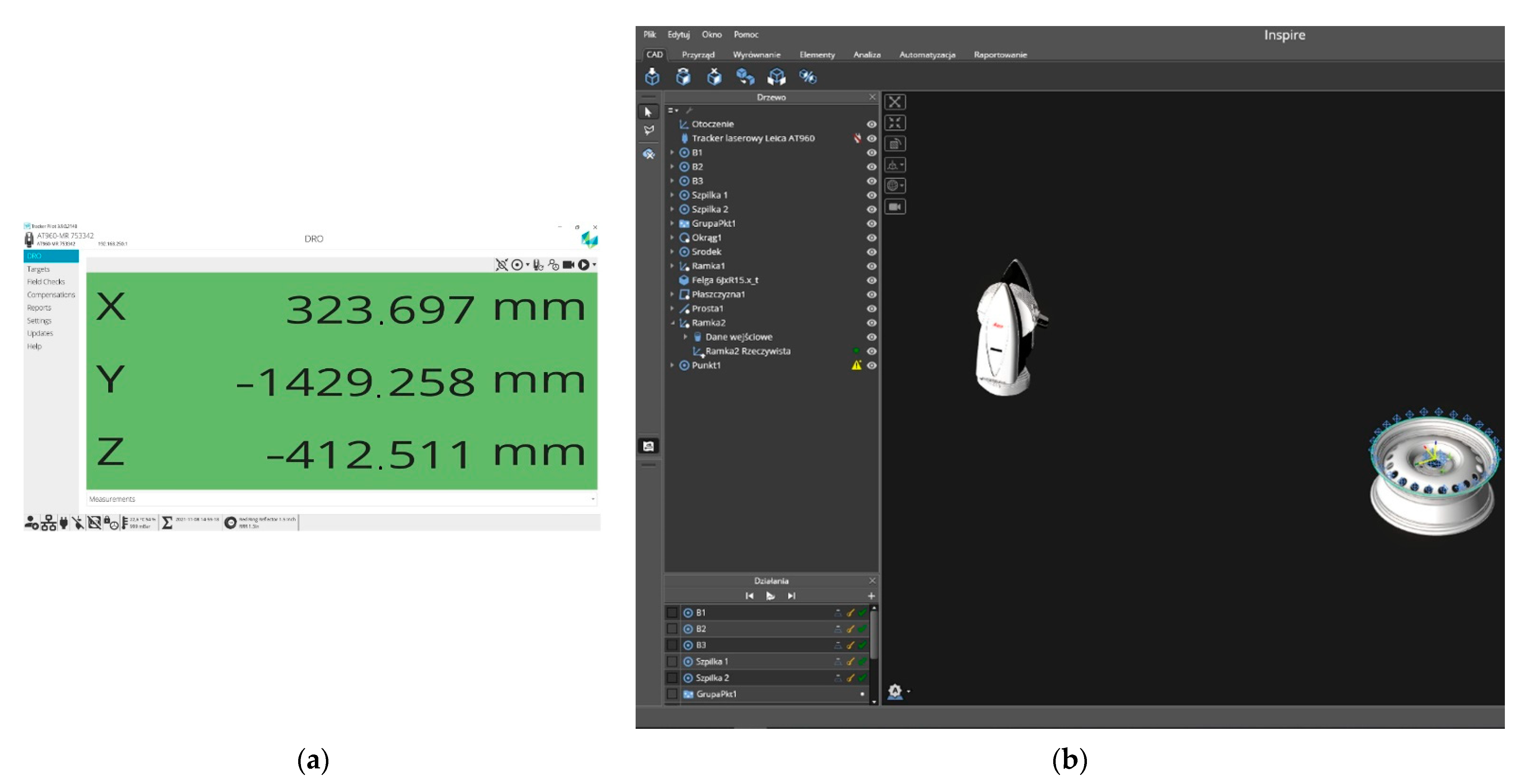
The tracker was delivered with two types of software offered by the manufacturer. The basic tool for operating the Leica tracker is the Leica Tracker Pilot program (
Figure 2a). The program is a graphical interface between the user and the tracker controller. It allows the user to enter all settings into the tracker, save measurements as text files, and perform maintenance and calibration. After establishing a connection with the tracker, the program displays status information, sensor states, and measurement values of the currently tracked object.
The triggering of measurements depends on the selection of one of the 7 measurement profiles:
single quick measurement;
single standard measurement;
single precise measurement;
continuous measurement triggered at a constant distance;
continuous measurement triggered at a specified time;
measurement triggered by a touch probe;
measurement triggered by an external signal.
The software allows the user to save the collected measurement data to a CSV file. In addition, it also has several tools for checking the measuring accuracy of the tracker head, reflectors, and measuring probes. Sudden temperature changes, as well as various mechanical influences, may adversely affect the accuracy of the device. Therefore, in addition to checking the accuracy of the Tracker Pilot, it is possible to perform a compensation procedure, which allows for maintaining high accuracy of measurements. The software does not have any tools for the visualization and processing of collected data.
The second program provided by the tracker manufacturer, called Inspire (
Figure 2b), a metrology program, is used for this purpose. The software allows the user to create measurement procedures, automating the process of not only data acquisition but also the processing and generation of measurement reports on their basis. The software automatically connects to the measurement devices and supports all 7 measurement trigger profiles for the tracker. The great advantage of this software is the ability to define the dimensions of the shape of the stands for measuring reflectors. Then the software automatically converts the position of the measured point to the point of contact of the stand with the measured surface. The bases can come in various shapes depending on their purpose. The simplest ones are used to measure flat surfaces. More complex shapes make it easier to measure edges or characteristic points of curved shapes. The software can independently recognize the measured shape based on the arrangement of measurement points and adjust the settings for the detected shape. It also allows the user to import CAD files and has tools to define the relationship between the measurements and the shape pattern. In general, the software is very user-friendly, with a large set of advanced features that are intuitive to use. However, it has its limitations. For T-Mac probe measurements, only positions. For robot-related measurements, recording both position and orientation is very important.
Tracker Pilot software records positions and orientations but does not have any tools to process this data. A tool designed for measurements used in robotics is the RoboDyn software, which allows the user to determine the base frame of reference, the tool center point (TCP), based on measurements from the tracker. The software can also measure the accuracy of an industrial robot and perform calibration and compensation of its parameters. In addition, the tracker can work with many other types of software, such as PolyWorks®, Metrolog X4, DM Works, Silma/X4-iRobot, or RoboDK.
All of the software types mentioned above have their advantages and disadvantages. Unfortunately, none of them offers convenient and fast online communication with various types of robots and with the Matlab-Simulink package.
Thus, several possibilities for downloading measurement data from the tracker were considered:
reading data from a CSV file;
using the RTFP-EC accessory to communicate with the tracker via the EtherCat protocol;
using the tools available in the SDK to communicate with the tracker via TCP/IP protocol.
Taking measurements and saving the data to a CSV file is possible in both programs supplied with the tracker, which were described earlier. This approach is convenient for a small number of individual measurements. Exporting a large series of measurements, especially continuously triggered measurements, is cumbersome because both programs we tested do not have formatting capabilities for data export. In addition, such an approach precludes the use of data for real device control. A solution designed for such applications is a tracker add-on called RTFP-EC that allows data to be sent over EtherCat protocol at a frequency of 1 kHz. This is an Ethernet-based communication standard. This protocol allows for achieving high speeds of information exchange and can be used for communication in real-time systems [
41]. According to studies reported in papers [
42,
43,
44,
45], EtherCat is one of the most efficient industrial communication standards available on the market. But its implementation costs are lower than Profinet or Powerlink [
41]. Many platforms used in robotics, such as the RaspberryPi, support EtherCat, particularly for controlling drives. The Matlab/Simulink environment also has a set of tools for communication over EtherCat. Unfortunately, ABB’s robots do not support this communication standard. Therefore, the authors finally decided to use a simple TCP/IP connection, which will allow ABB’s robot controller and other devices and applications that support an Ethernet connection to receive measurement data. Such a connection transfers data at 50 packets per second [
46]. This means that for serial measurements with a high trigger frequency, data is buffered and sent every 20 ms, but without maintaining the timing regime. Thus, it is not suitable for real-time applications. On the other hand, it can be used for robotic metrology processes, registration of robot trajectories, and correction of low-dynamic motion trajectories.
The requirements that were set for the development of the new software included:
online communication with the laser tracker;
use of a popular, universal communication standard;
possibility to choose the type of tracker measurement;
possibility of triggering the measurement with a tracker at a defined time or distance;
the possibility of triggering the measurement by a touch probe or an external signal;
use of a popular object-oriented programming language that provides access to many libraries in the form of packages.
Analyzing the available possibilities, it turned out that two leading manufacturers of laser trackers, namely Leica and Faro, offer their own software development kits (SDK). Having a Leica tracker, it was decided to use the SDK offered by the manufacturer based on the NET programming platform. Still, it is also available in other programming languages (e.g., Python). The API, i.e., the application programming interface provided by the SDK, has the structure of an object tree. This approach means that the Tracker object is represented by subobjects containing properties, events, and methods. Their feature is the availability of events informing about changes in the tracker’s status. The further part of the paper describes the developed application based on the available SDK and using the Python language.
3. The Application of the Developed Software in Robotics
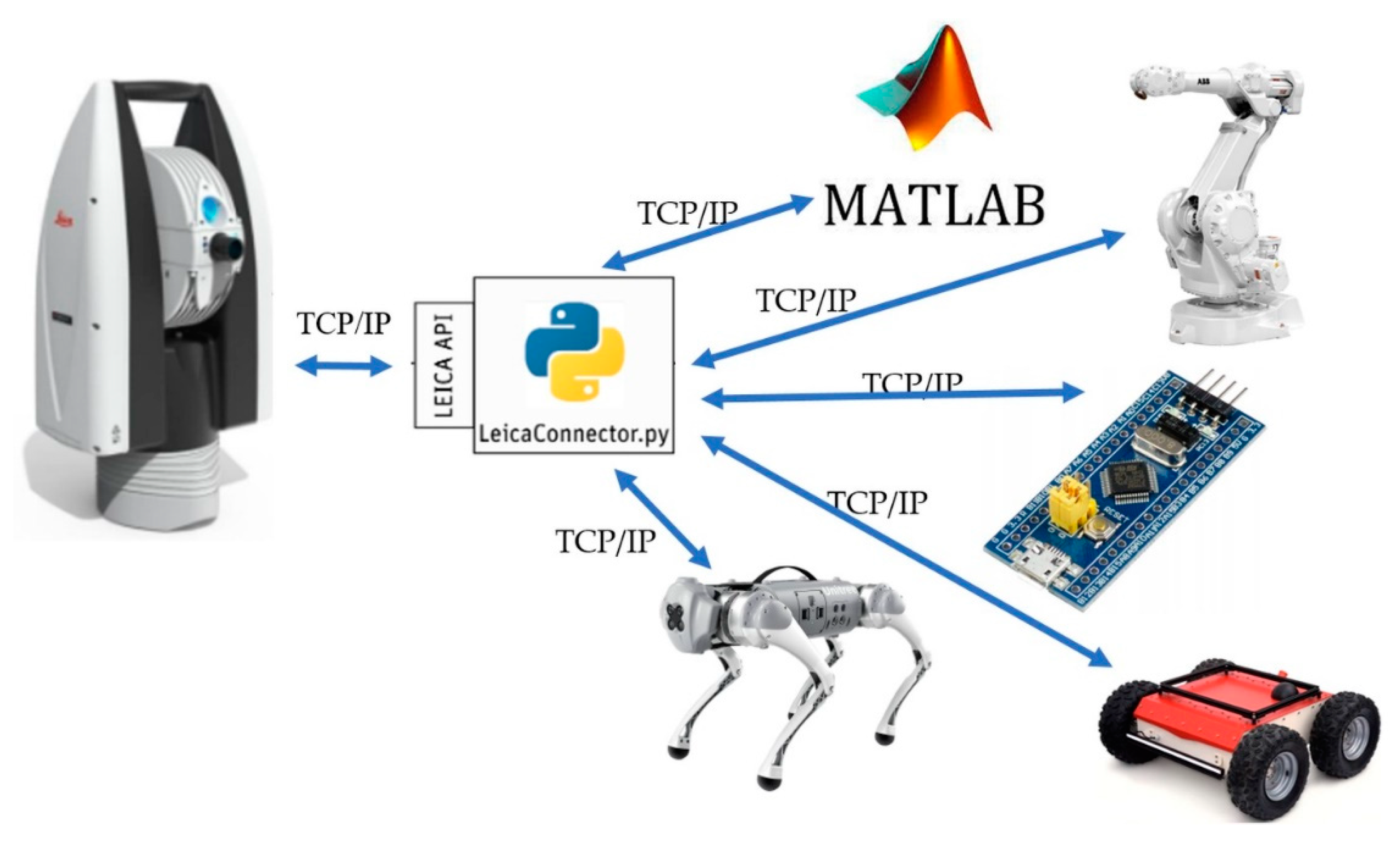
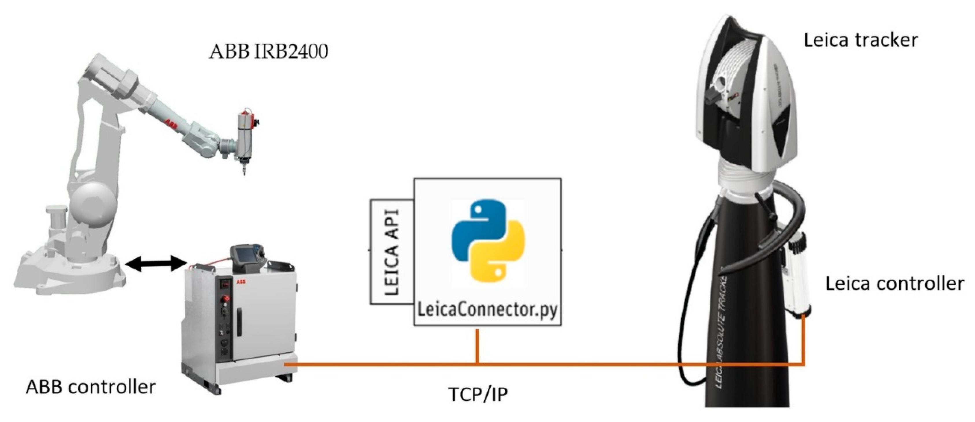
The developed application was named LeicaConnector.py. It is a TCP server running on a PC under Windows. Devices implementing the TCP/IP interface can connect to it. The server processes the defined TCP frames and performs functions on the tracker based on the API (
Figure 3).
The implementation of such an intermediary in communication with a Leica device allows for:
Leica device support by microcontrollers with TCP support, industrial robot controllers, mobile robots, or engineering packages, e.g., Matlab-Simulink;
easy program development by defining subsequent commands available to the client;
the ability to send the position and orientation (in the case of T-MAC) read by the Leica device to multiple devices;
easy integration of measurements from the laser tracker with data from other devices.
The choice of the Python language, in the context of the design requirements set, is determined by its versatility and universality of use, especially in applications related to the Internet of Things and data engineering [
47]. Due to the available SDK, there was an opportunity to use, for example, the C# language. However, given that the software runs on commands, an intuitive direction for its expansion is to integrate further measurement devices, i.e., a 2D scanner or another Motion Capture type position determination system. This approach is another point justifying the use of Python, as due to its popularity, many manufacturers are developing their APIs in it. The described approach of software development ultimately leads to the creation of a universal tool for the acquisition and integration of measurement data. Its processing is the domain of data engineering. In this field, Python is the language of first choice due to the multitude of libraries for data processing and visualization. This is another argument for choosing Python.
The LeicaConnector.py program is based on a configuration file in which, among others, the settings of the graphic interface are saved, the client command codes are assigned to the functions they perform, and the network settings are defined, i.e.,
[TCP]
Ip = 192.168.123.11
Port = 50007
[TRACKER]
Ip = 192.168.123.31
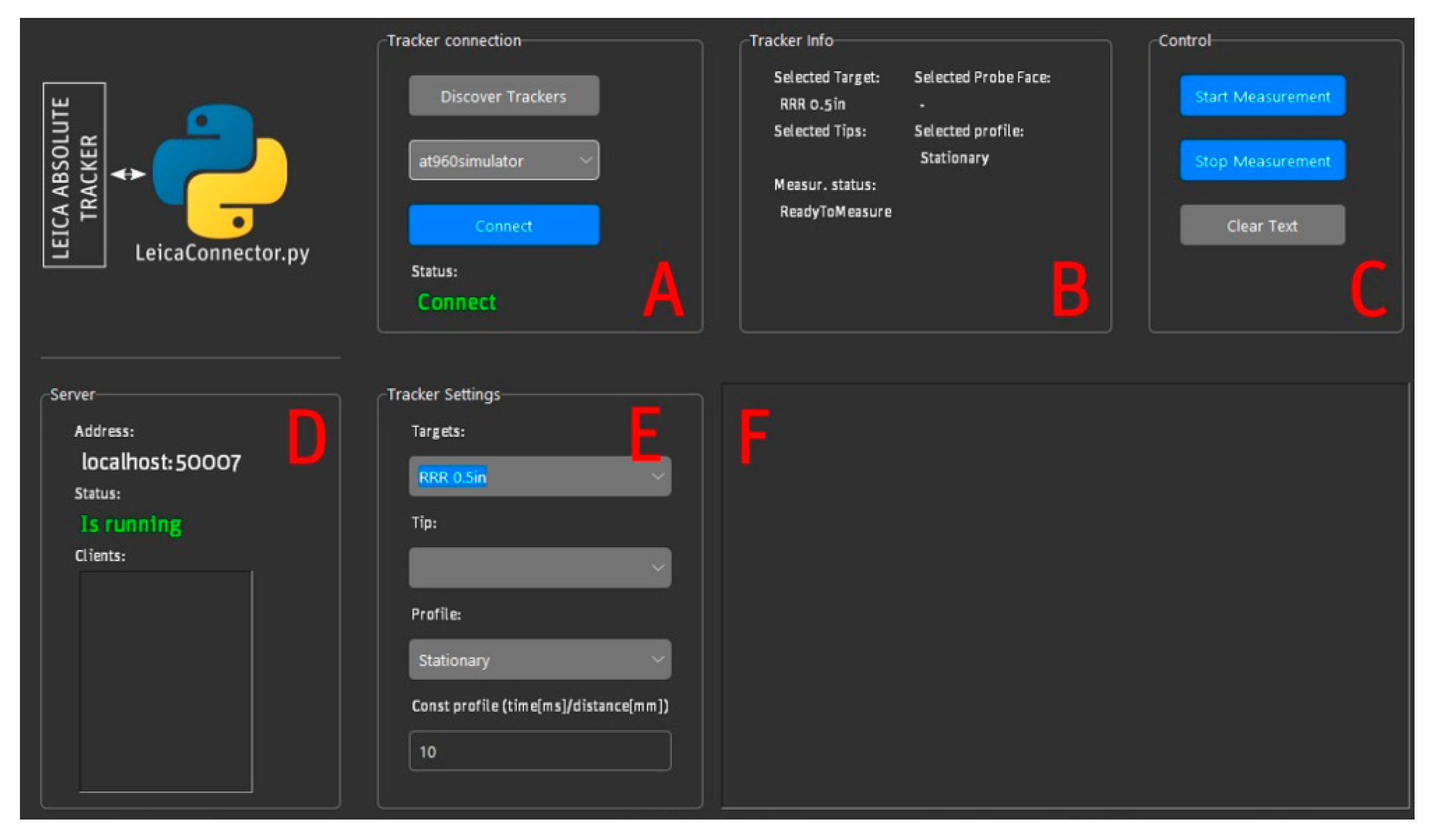
The [TCP] section defines the IP number and port of the server being created, to which the clients connect. The [TRACKER] section defines the default Leica device IP or the simulator name, as shown in the section of the configuration file (the line marked in green is a comment). The LeicaConnector.py interface comprises six sections, identified as A–F in
Figure 4.
In section A, there is a tracker checkbox. The list of available devices can be updated by selecting the Discover Tracker button. Connection with the selected device takes place by selecting the Connect button, and the correctness of the connection is indicated in the Status field. Section B contains basic information about the configuration of the Tracker, related to the selected target and its configuration (ProbeFace and Tips), the measurement status, and the selected measurement profile. This can be selected by the client by sending the appropriate command in the form of a data frame with the appropriate code. The program allows the user to select several profiles:
In the case of the continuous time and constant distance profile, the configuration frame has a parameter that defines, respectively, the time interval between measurements or the change of the distance for which the measurement will be triggered. Although the default, triggering or ending the measurement is triggered by the client by sending a frame with a defined code. In section C, buttons allow the user to perform these actions from the GUI level. The Clear Text button clears the window in section F, where program logs are placed. Section D contains information about the configuration of the TCP server being created and the list of clients that are connected to it. The client who connected first has the right to issue commands. Subsequent customers only receive the measurement data. Section E is used to select a target and configure it if more than one tip is defined in the tracker controller. In this section, the user can select a measurement profile. This is equivalent to executing the appropriate command by the client. In the case of a continuous time profile and a constant distance, the set interval or distance value results from the value entered in the Const Profile field. Section F is a window where the logs of the program are displayed. LeicaConnector.py requires the following:
Python version 3.8.10;
Tkinter library;
Python.NET package.
In the case of communication with a client in the local network, the IP number of the host should be specified in the IP parameter. Two types of frames are exchanged between the LeicaConnector.py proxy and the client using a TCP/IP connection.
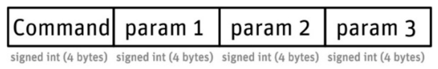
The first type of frame consists of four fields (
Figure 5):
Command—a field in the signed int (4B) format; the field specifies the frame type through the code it contains: command frame, confirmation/error frame, or measurement frame;
param 1—a field with data in the signed int (4B) format, the interpretation of this parameter depends on the code contained in the command field;
param 2—a field with data in the signed int (4B) format, the interpretation of this parameter depends on the code contained in the command field;
param 3—a field with data in the signed int (4B) format, the interpretation of this parameter depends on the code contained in the command field.
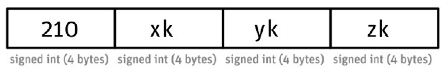
A special frame of the first type is the frame with code 210 (
Figure 6), the parameters of which param1-param3 correspond to the coordinates of the measuring point (target). Their values (returned by the tracker), due to conversions to integers, are scaled by the constant value of k.
When the Laser tracker works with T-MAC probes, the orientation of the T-MAC probe is returned in the form of a quaternion in addition to the position of the point in the tracker’s coordinate system. In this case, the measuring frame (
Figure 7) has code 211, and its fields are not only positions (x, y, z fields) but also values of the quaternion coefficients (a, b, c, d) scaled by the constant
m.
The assumed values of the constants are, respectively, k = 1000 and m = 10,000. Changing them requires modifying the GainPoz and GainRot constants in the configuration file. The frame codes are three-digit numbers, where:
1xy—command codes;
2xy—confirmation codes corresponding to the command code. The exception is the frame with the code 211 (position and orientation data) for the command 210;
30y, 3xy—general error codes and command error codes, where x = 1, 2..9, y = 0, 1..9.
The following command codes and the associated confirmation or error codes were adopted in the developed application:
110—measurement start command, runs the startMeasurement function;
112—measurement end command, triggers the stopMeasurement function;
115—command sets the stationary measurement mode;
116—the command sets the measurement profile of the continuous time type;
117—the command sets the measurement profile of the fixed distance type;
118—the command sets the contact type measurement profile.
The example shows how LeicaConnector.py communicates with the client when using a stationary measurement profile. It is assumed that the used retroreflector is visible to the tracker.
Client: Connecting to the LeicaConnector.py server
Client: Send the frame: [0,0,0,110]
LeicaConnector.py: Frame sending: [210,1,000,000,1,523,234,5,432,984] //other customer activities
Client: Send the frame: [110,0,0,0]
LeicaConnector.py: Send the frame: [210,1,000,000,1,523,234,5,432,984]
In the example shown, the client sends a frame with code 110, which corresponds to triggering the measurement in the stationary mode (the default). In response, LeicaConnector.py sends a frame with the code 210, the next fields of which are the coordinates of the measuring point on the x, y, and z axes. Their values are multiplied by 1000. Hence: x = 1000, y = 1523.234, z = 5432.984. Then (step 4), the client sends another frame with the code 110, requesting another measurement in stationary mode. This one is passed in step 5.
The developed application allows for handling possible communication errors, handling various methods of triggering measurements, and measuring in stationary mode with the T-MAC touch probe. The following part shows the application of the developed software in robotics.
4. Examples of Applications of the Developed Software
The software presented in this paper was originally developed to communicate with ABB’s industrial robots. While working on the aforementioned paper [
37], an idea emerged to provide data transmission from a laser tracker. That article concerned using a laser tracker to program the paths of industrial robots, and there is no need to quote the results here. It is important that after developing the software, the communication diagram of the industrial robot laser tracker was modified (
Figure 8).
The introduced modification allows the user to avoid the need to read text files with data. In addition, data transmission is faster, and the algorithms introduced in the future to the application will allow for the automatic determination and translation of robot coordinate systems.
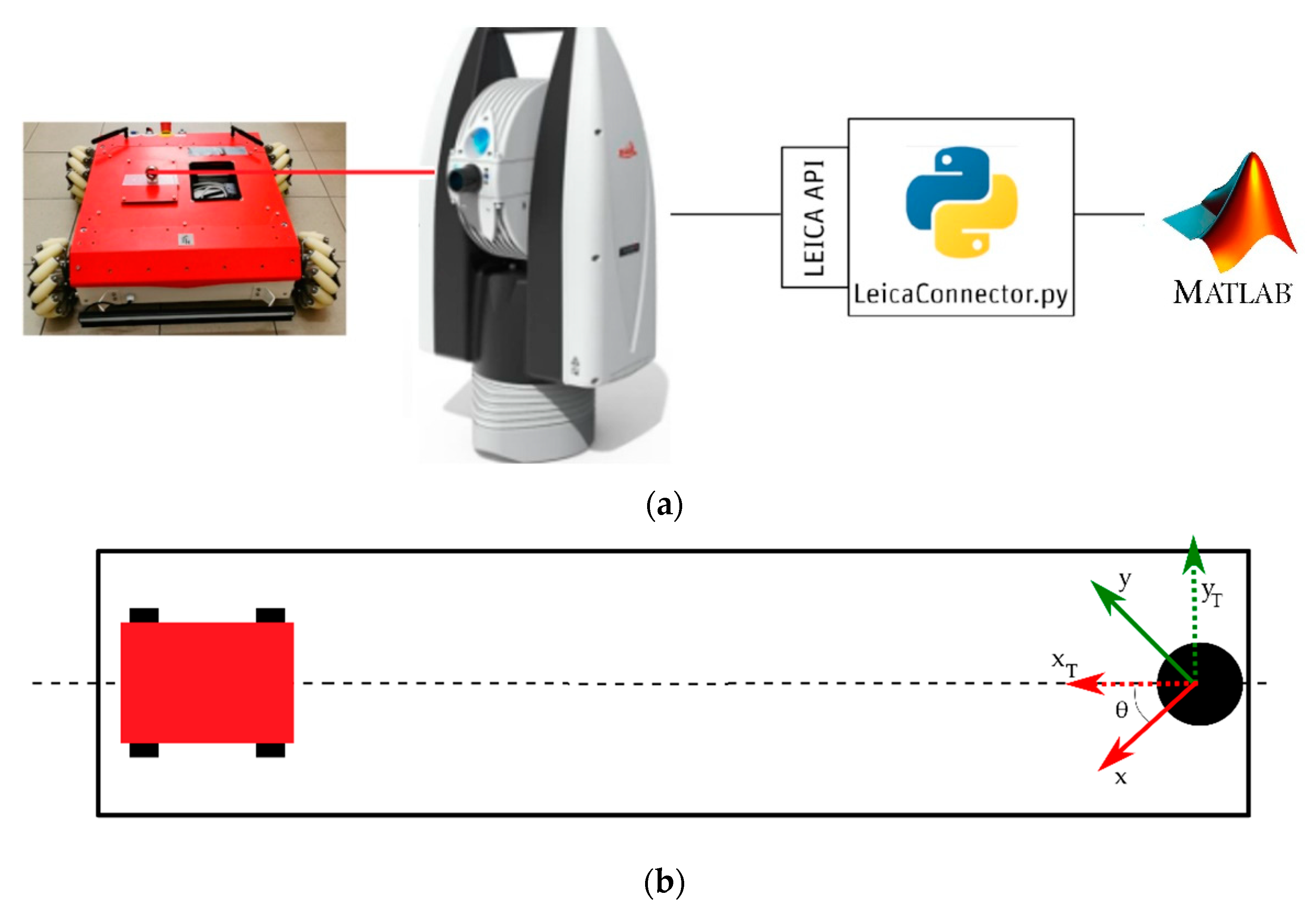
In the further part of the paper, an example of the use of a laser tracker to determine the position of mobile robots is presented in the example of two constructions: a 4-wheel mobile robot with mecanum wheels and a 4-leg mobile GO1 robot.
The Department of Applied Mechanics and Robotics has a 4-wheeled mobile Panther robot manufactured by Husarion, equipped with mecanum wheels. The Raspberry Pi 4 microcomputer with the ROS system, connected via the CAN bus with the STM microcontroller implementing the lower control layer, is responsible for high-level control. Moreover, the robot allows hardware access to motors and encoders and implements the lower control layer using the rapid design environment based on the dSpace signal processor. This approach allows for the implementation of research work on traffic control algorithms or identification of the mathematical model.
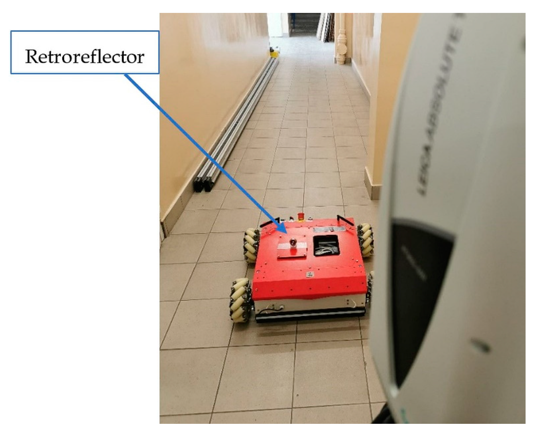
In the described example, the Leica laser tracker was used to determine the position of the mobile robot in relation to the tracker coordinate system during the movement (
Figure 9), which was carried out in the so-called joystick control mode. This feature is ROS-enabled. Successive positions of the mobile robot, understood as positions related to its design of the retroreflector, were saved in the Matlab software using the LeicaConector.py program (
Figure 10a). In this case, the laser tracker determined the retroreflector positions in a time-related trigger mode with an interval of 0.1 s.
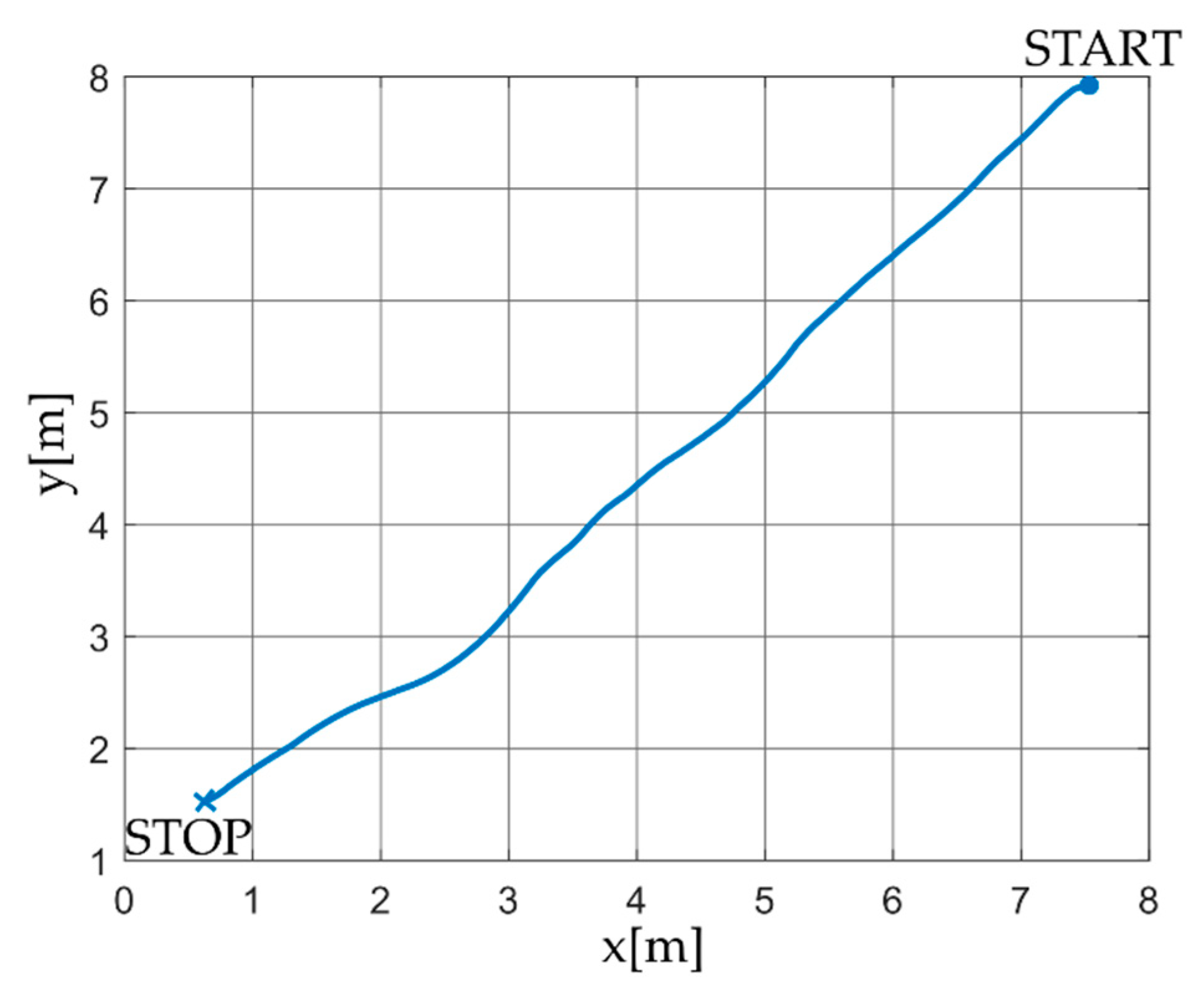
In mobile robotics, it is important to measure the position on the XY plane. During the drive of a 4-wheel mobile robot with mecanum wheels, measurement samples of the reflector’s position were recorded. For the assumed time interval, the first 130 samples correspond to 13 s of the motion of the mobile robot. On this basis, the path of the robot’s characteristic point was determined (
Figure 11), related to the retroreflector in the tracker system.
The experiment in which the laser tracker determined the position of the robot while moving was carried out in a rectangular corridor. There is a tracker at one of its ends. The second one was the initial position of the mobile robot, as shown in
Figure 11. The length of the radius vector
of the robot’s characteristic point for its initial position in the tracker coordinate system is approx. 11 m and for the end position its value is approx. 3.3 m. Moreover, it can be seen from
Figure 10b and
Figure 11 that the robot’s movement was towards the tracker. The path determined by the tracker indicates that the angle between the corridor axis and the OX axis of the tracker system is determined by the relationship
where
is the coordinate of the robot’s initial position determined in the first measurement; it is approx. −46.5°, which is marked in the diagram in
Figure 10b.
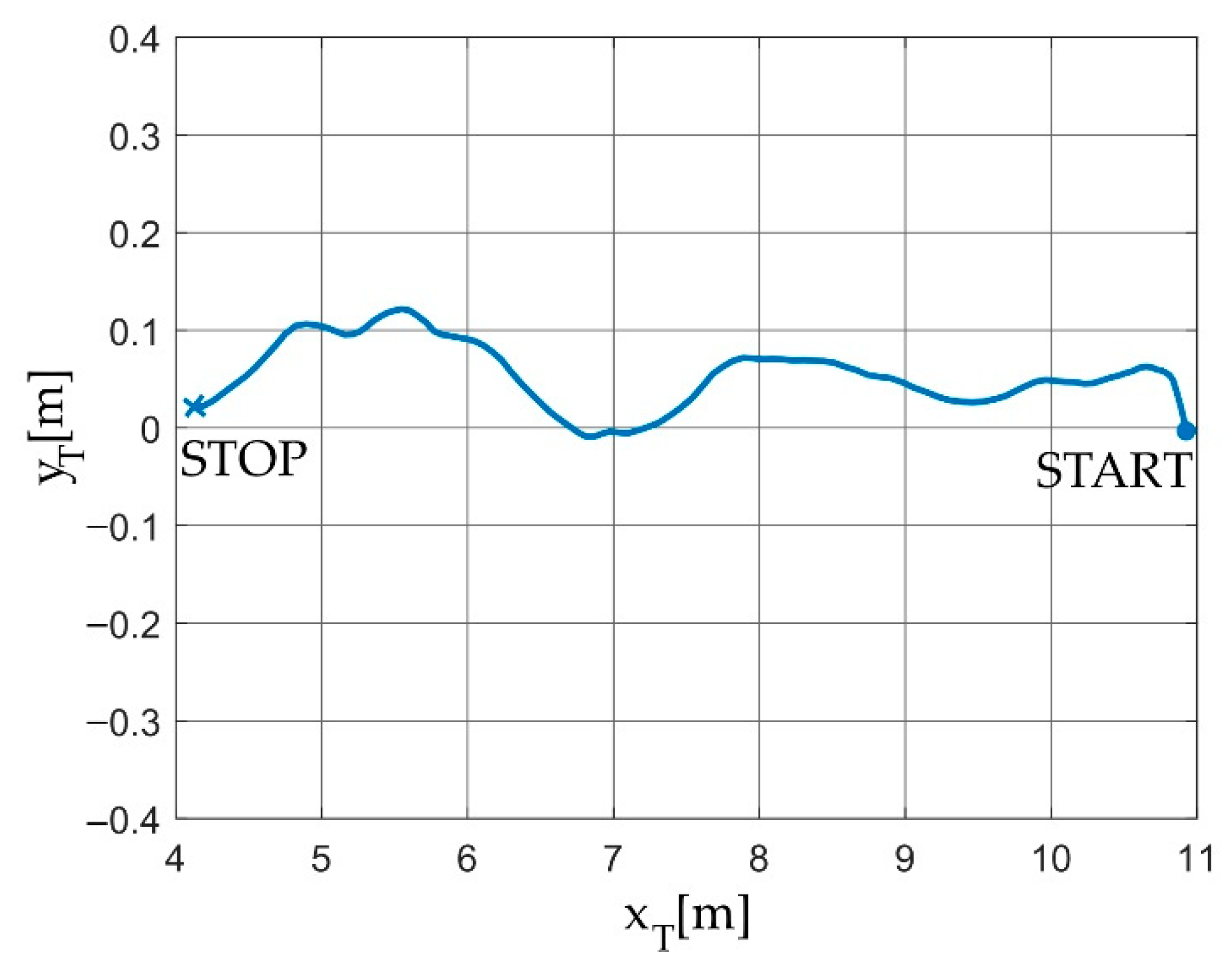
Applying a homogeneous transform describing a rotation on a plane having the form
it is possible to determine the path of motion of MRK in the
coordinate system related to the tracker, whose axis OX is parallel to the corridor axis (
Figure 10b). The resulting trajectory is shown in
Figure 12.
Figure 12 shows that the 4-wheeled mobile robot with mecanum wheels changed its position in relation to
during the movement. Changes in the position along the
axis result from imprecise control and skidding of the mecanum wheels.
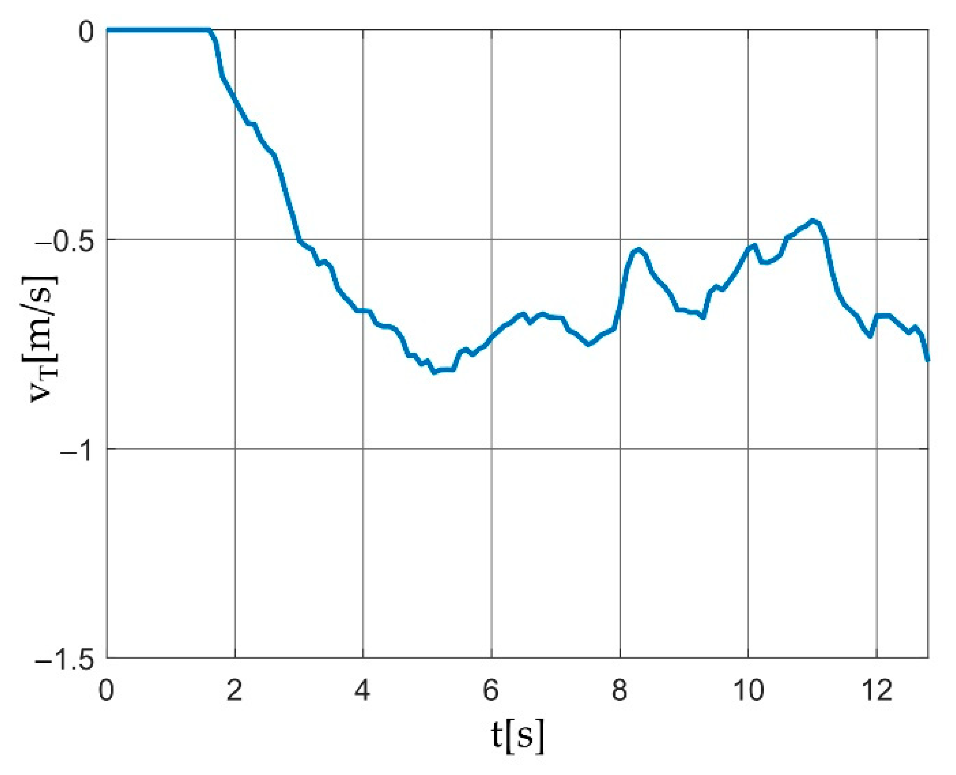
The example discussed here shows the possibility of using a laser tracker to determine the position of a mobile robot in relation to the adopted coordinate system. Moreover, the known time interval between measurement triggers allows for the determination of the remaining kinematic parameters of the robot. Using the finite difference method, the value of the velocity vector of the characteristic point of the robot with which the retroreflector was associated in the
system was determined. Its course is shown in
Figure 13. The waveform shows that the robot movement started before the 2nd second. Velocity values remain negative because its projection on the axis is opposite to the axis direction. The observed changes in the velocity value during the movement are caused by the use of the joystick control mode.
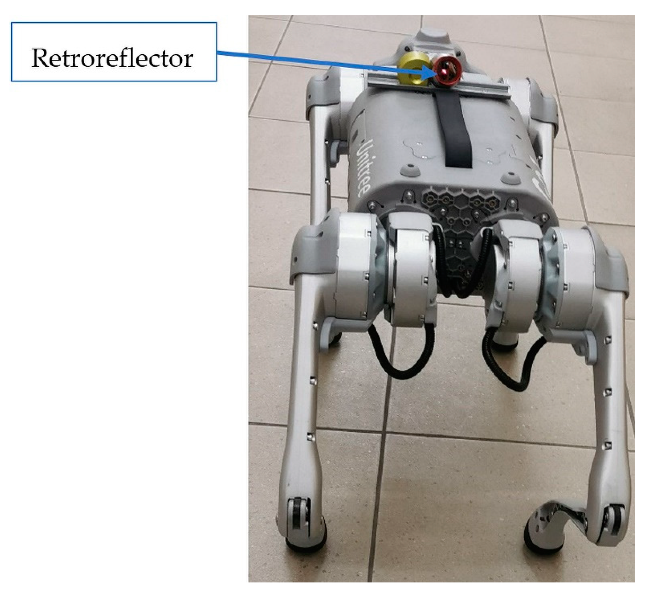
The UNITREE 4-legged GO1 robot, shown in
Figure 14, is the second structure, the path of which was determined using a laser tracker.
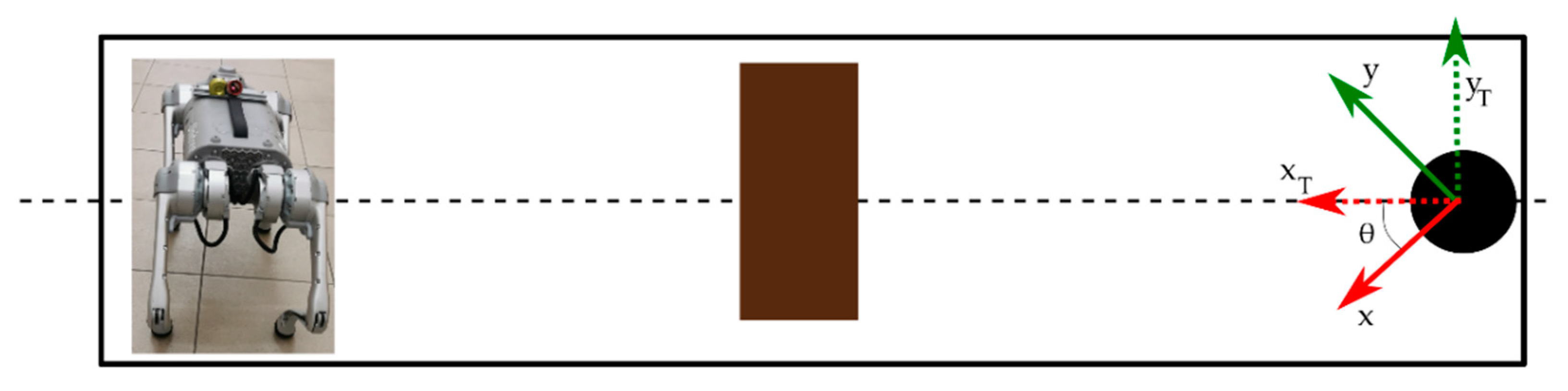
The robot weighs 12 kg, and its maximum speed is 4.7 m/s. The design is supported by the Rasberry pi 4 microcomputer and NVIDIA Nano chips, which are associated with five cameras. The construction includes a joystick that allows the user to control the robot and perform predefined movements or select modes, e.g., climbing/descending stairs. From a programming point of view, it is important that Unitree provides a ROS-based API. Like the 4-wheeled mobile robot, the GO1 robot moved along the corridor during the tests (
Figure 15). However, in this case, an obstacle with a height of about 77 mm was added. Its presence is to test the ascending/descending stairs mode.
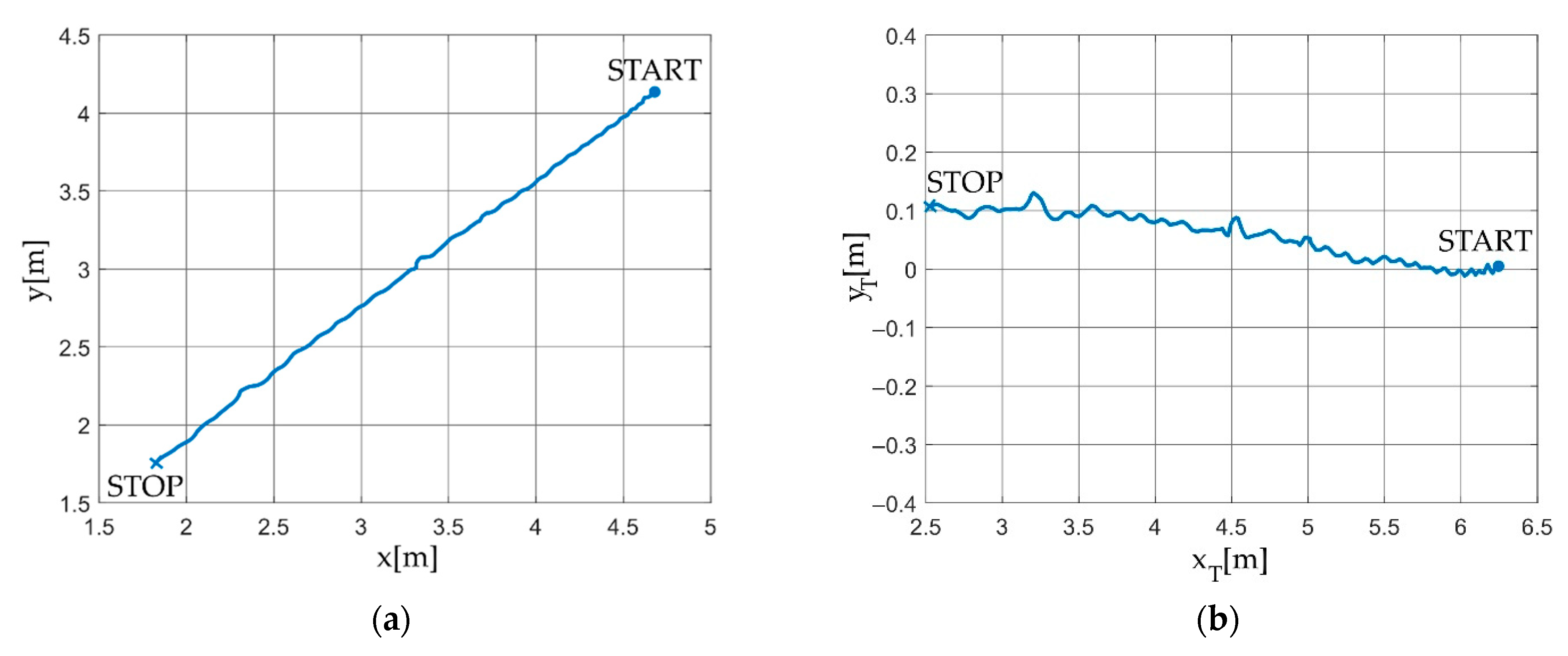
Proceeding analogously to the previous example, the path of the GO1 robot controlled by a joystick on the xy plane was determined, as shown in
Figure 16a.
Figure 16b shows the path in the transformed coordinate system. In this case, the angle
41.5°.
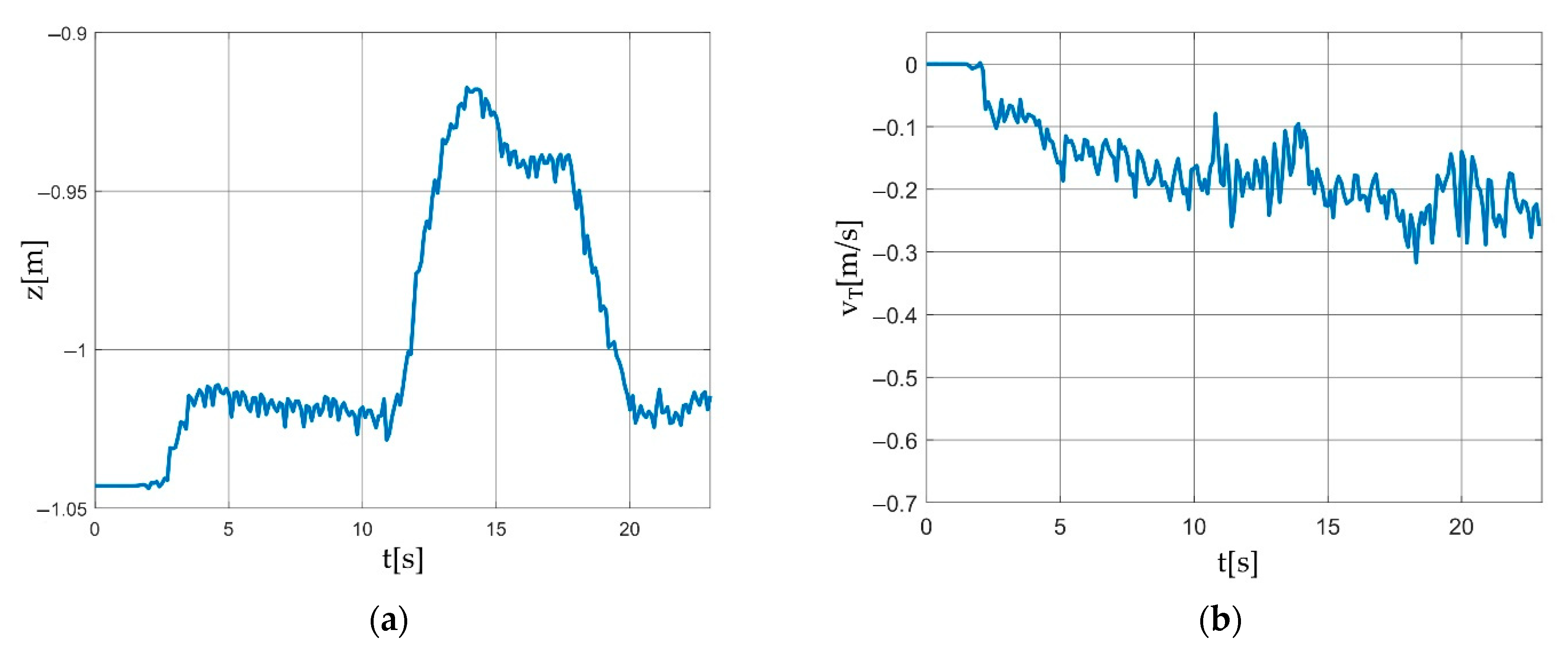
The fact that the GO1 robot overcame an obstacle placed in the test environment can be seen in the z-coordinate (in the system related to the tracker) of the GO1 robot characteristic point. Its course is shown in
Figure 17a.
Figure 17b shows the velocity of the characteristic point of the GO1 robot. The presented example shows the legitimacy of using the developed application and the laser tracker to record the trajectory of a walking robot.
5. Discussion
The presented article is primarily of an engineering nature. The solution review performed was based on our own need for some software to share laser tracker data for robots. Different methods of performing a literature and solution review can be adopted. Here, the process was based on searching for applications useful in industrial and mobile robot research. According to the authors, the available commercial solutions and those described in the articles proved unsatisfactory and lacked versatility.
The adopted criteria the developed software was to comply with were based on the preference for using the Matlab package, ABB industrial robots, and Raspberry pi microcontroller-based mobile solutions. It can be assumed that, for example, in Scilab software, Kuka robots, and STM family microcontrollers, the criteria could be slightly different. Due to the need to develop a totally new application, the Python language and TCP/IP protocol were chosen. The choice made was based on the advantages of the solutions presented and experience in programming in Python and implementing projects using the TCP/IP protocol. Competing solutions based on, for example, the C# language and the EtherCAT standard are possible, but the advantages of the selected solutions proved decisive for the authors.
The developed and characterized software is in the development stage. It meets the adopted criteria and performs the main functions. However, it requires adding functions to expand its capabilities. There is a lack of visualization of measured positions, the ability to import CAD files, and the recalculation of positions with respect to a coordinate system other than the tracker has not yet been implemented. A particularly useful feature will be to recalculate the coordinates of measured points relative to the base system of an industrial robot. This function will appear in version 2.0 of the software and allow for the measurement and direct recording of points useful for programming robot paths or correcting workpiece positions. One of the novelties presented in the article is the selection and identification of tracker applications in robotics. Among the many possible applications of trackers, the authors have limited the examples to this field. In addition, for applications in robotics, the authors formulated specific criteria that the software that shares data from the tracker should comply with. Performance review, along with the advantages of programming languages and communication standards possible to use in such a project, can also be considered a novelty. The software itself is also new, with the characteristics of its construction and operation. After adding the above-mentioned necessary functions, it will be made available to Leica and all interested parties, along with the source code for its use and development. The authors hope that the developed software will be used in solutions where online robot-tracker laser communication from Leica is necessary.
6. Conclusions
The paper presents the concept of operation and methods of using laser trackers in robotics. The analysis shows that trackers can be successfully used to track the movement of mobile robots. They allow for precise measurements of traffic parameters. An interesting and intensively developed topic is the real-time correction of paths of manipulation robots. The conducted analysis indicates that the applications of trackers are described very widely; however, there is no characteristic of work on the development of software for sharing and exchanging data with trackers. A real-time data exchange tracker is a device that supports TCP/IP communication allowing for building advanced, very precise solutions in various fields. The shortcomings in the tools available on the market and our own demand resulted in developing our own software. The developed solution is based on the SDK provided by Leica and the Python language. The structure and functioning of the developed application have been described in detail. The software meets the goals set at the beginning of the design process regarding online communication with the tracker and the use of the universal popular TCP/IP standard, thanks to which it enables data transfer to most devices available on the market; especially industrial PLCs and robot controllers from various manufacturers. Python, a general-purpose, high-level programming language with an extensive library package, allows for adding new functionalities to the application. As part of further work, it is planned to expand the program with the automatic creation of coordinate systems and positions measured in relation to them. For applications in manipulative robotics, adding options related to determining the TCP of the robot with the use of a tracker, base system, and calibration of selected robots are planned. In the discussed application, it is planned to add functions related to the correction of TCP online position based on data from the tracker. The real-time correction will be performed based on the position of the robot controller and the position of the tracker. For the correction, it is also planned to use other data sent from the robot in the TCP/IP standard, namely parameters related to the contact force or the process being carried out.


 ,
, 


