
Design and Implementation of a Metadata Repository about UML Class Diagrams. A Software Tool Supporting the Automatic Feeding of the Repository


Abstract
:1. Introduction
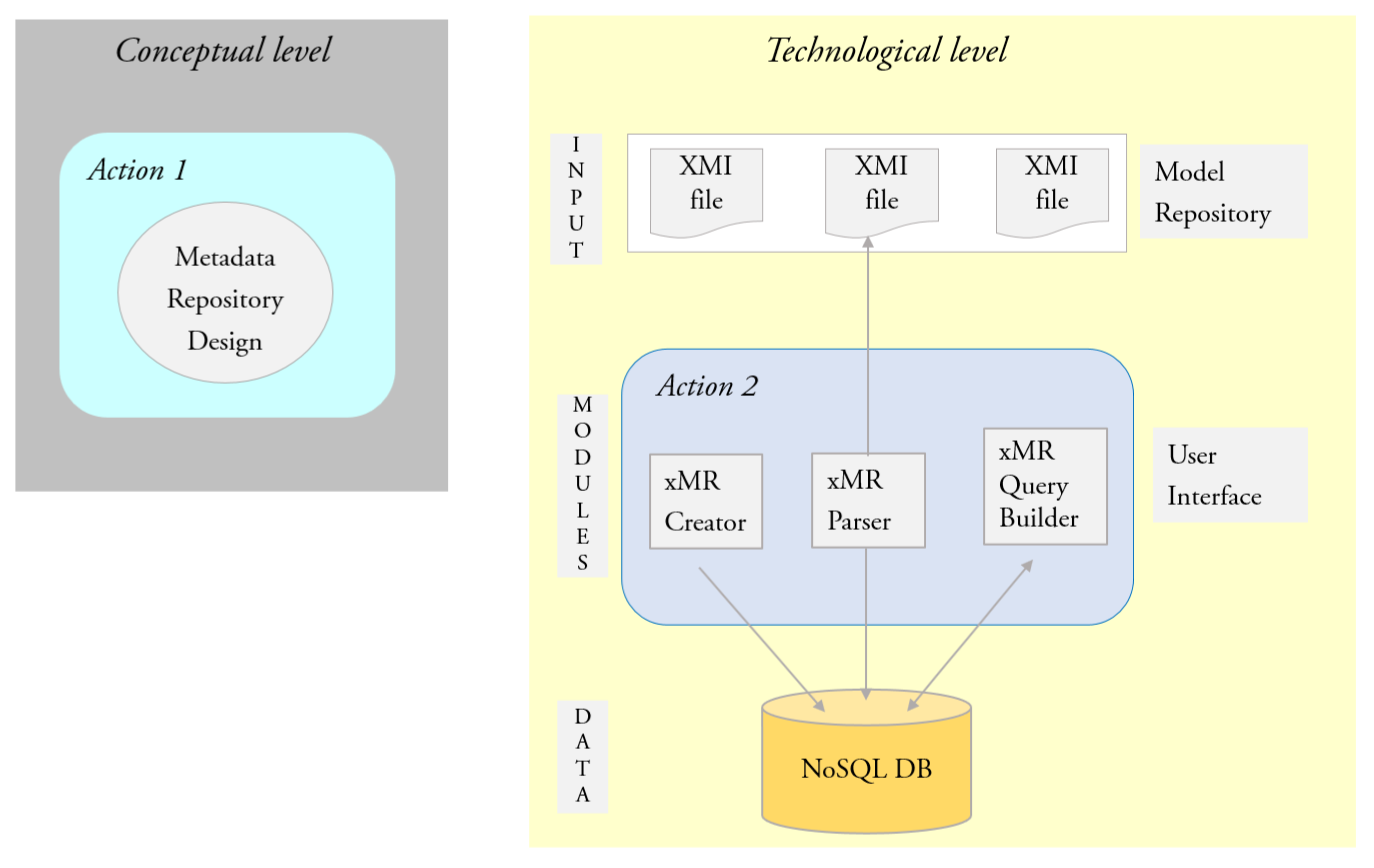
2. Our Approach
2.1. Action 1
2.2. Action 2
- The Model Repository of the company contains the XMI files about UML class diagrams. These files are the input data for the overall process for building and feeding the metadata repository about such a category of artifacts.
- The User Interface is composed of three software components: xMR Creator, xMR Parser (in [16], xMR Parser is called XMI_to_Parser) and xMR Query Builder. They support, in turn, (a) the creation of an empty instance of the NoSQL DB; (b) the extraction of metadata from the XMI files and the copying of them into the NoSQL DB; (c) the instantiation of a predefined set of flexible query templates against the NoSQL DB.
- The NoSQL DB layer denotes the Metadata Repository about UML class diagrams in the Model repository.
3. UML Metamodel for a Metadata Repository about Class Diagrams
4. The Schema of the Metadata Repository
- -
- project(projectID, name);
- -
- package(packageID, name, URI, projectID);
- -
- class(classID, name, packageID, associationClass, parent);
- -
- operation(classID, list);
- -
- attribute(classID, list);
- -
- association(associationID, name);
- -
- associationEnd(associationEndID, name, classID, associationID).
5. Architecture and Implementation of the XMI Parser
- The MVC controller layer corresponds to the controller package. It contains 1 class that is responsible for loading the Java Server Page (JSP) views, handling events, user actions and the navigation logic.
- The Model layer corresponds to the model package, which contains 7 classes in the entity subpackage and 1 class in the dto subpackage. The entity package contains Plain Old Java Objects, which correspond in number and structure to the database tables (Section 4). For instance, AssociationEntity corresponds to the association table.
- The Repository layer corresponds to the repository package. It contains 7 interfaces, one for each entity class of the model package, which extend the CRUDRepository interface of Spring.
- The Service layer corresponds to the service package. It is structured as 8 interfaces and 8 classes; the latter implement the former. The classes use the relative interfaces of the repository to query the database. The ParsingServiceImplementation class uses the services of the other classes to insert the metadata extracted from the XMI file, as a single database transaction.
- The 2 utility classes contain constants and variables used to carry out the needed checks.
- The webapp package collects 2 views. They are 2 JSPs that implement the user interface of the web application. The first JSP is responsible for the loading of the XMI file from the user; then, such a file is passed to the controller for the parsing (Figure 10); meanwhile, the second one shows the result (either “Success” or “Error”).
6. Case Study
7. Related Work
8. Conclusions and Future Work
Author Contributions
Funding
Data Availability Statement
Conflicts of Interest
Appendix A. The Schema of the Metadata Repository
Appendix B. The Instance of the Metadata Repository

Appendix C. Querying the Metadata Repository


References
- Bucchiarone, A.; Cabot, J.; Paige, J.R.F.; Pierantonio, A. Grand challenges in model-driven engineering: An analysis of the state of the research. Softw. Syst. Model. 2020, 19, 5–13. [Google Scholar] [CrossRef] [Green Version]
- OMG Unified Modeling Language, Version 2.5.1. OMG Document Number: Formal/2017-12-05 Normative. Available online: https/www.omg.org/spec/UML/ (accessed on 5 September 2021).
- Rumbaugh, J.; Jacobson, I.; Booch, G. The Unified Modeling Language Reference Manual, 2nd ed.; Addison-Wesley: New York, NY, USA, 2005. [Google Scholar]
- Di Rocco, J.; Di Ruscio, D.; Iovino, L.; Pierantonio, A. Collaborative repositories in model-driven engineering. IEEE Softw. 2015, 32, 28–34. [Google Scholar] [CrossRef]
- Keller, R.K.; Bédard, J.-F.; Saint-Denis, G. Design and Implementation of an UML-Based Design Repository. In Advanced Information Systems Engineering. CAiSE 2001; Lecture Notes in Computer Science; Dittrich, K.R., Geppert, A., Norrie, M.C., Eds.; Springer: Berlin/Heidelberg, Germany, 2001; Volume 2068, pp. 448–464. [Google Scholar] [CrossRef]
- France, R.; Bieman, J.; Cheng, B.H.C. Repository for Model Driven Development (ReMoDD). In Models in Software Engineering. MODELS 2006; Lecture Notes in Computer Science; Kuhne, T., Ed.; Springer: Berlin/Heidelberg, Germany, 2007; Volume 4364, pp. 311–317. [Google Scholar] [CrossRef]
- France, R.B.; Bieman, J.M.; Mandalaparty, S.P.; Cheng, B.H.C.; Jensen, A. Repository for Model Driven Development (ReMoDD). In Proceedings of the 34th International Conference on Software Engineering (ICSE), Zurich, Switzerland, 2–9 June 2012; pp. 1471–1472. [Google Scholar] [CrossRef]
- Gosala, B.; Chowdhuri, S.R.; Singh, J.; Gupta, M.; Mishra, A. Automatic Classification of UML Class Diagrams Using Deep Learning Technique: Convolutional Neural Network. Appl. Sci. 2021, 11, 4267. [Google Scholar] [CrossRef]
- Bernstein, P.A.; Dayal, U. An overview of repository technology. In Proceedings of the of the 20th International Conference on Very Large Data Bases, Santiago, Chile, 12–15 September 1994; pp. 705–713. [Google Scholar]
- Mayr, C.; Zdun, U.; Dustdar, S. Reusable Architectural Decision Model for Model and Metadata Repositories. In Formal Methods for Components and Objects; Lecture Notes in Computer Science; de Boer, F.S., Bonsangue, M.M., Madelaine, E., Eds.; Springer: Berlin/Heidelberg, Germany, 2009; Volume 5751, pp. 1–20. [Google Scholar] [CrossRef]
- Di Felice, P.; Paolone, G.; Paesani, R.; Marinelli, M. Overview of a Project devoted to Release an open-source Software Tool for the Creation, Feeding and Querying of a NoSQL Metadata Repository about UML Class Diagrams. In Proceedings of the 2nd International Electronic Conference on Applied Sciences, Basel, Switzerland, 15–31 October 2021. [Google Scholar] [CrossRef]
- Postgres NoSQL: Combining Developer Productivity with Enterprise Data Integrity. An EnterpriseDB White Paper for DBAs, Developers & Database Architects, July 2014. Available online: info.enterprisedb.com/rs/enterprisedb/images/EDB_WhitePaper_Postgres_NoSQL.pdf (accessed on 10 November 2021).
- Tran, N.V.; Ganser, A.; Lichter, H. Multi Back-Ends for a Model Library Abstraction Layer. In Computational Science and Its Applications—ICCSA 2013; Lecture Notes in Computer Science; Springer: Berlin/Heidelberg, Germany, 2013; Volume 7973, pp. 160–174. [Google Scholar] [CrossRef]
- Couto, R.; Ribeiro, A.N.; Campos, J.C. The Modelery: A Collaborative Web Based Repository. In Computational Science and Its Applications—ICCSA 2014; Lecture Notes in Computer Science, Part VI; Springer: Cham, Switzerland, 2014; Volume 8584, pp. 1–16. [Google Scholar] [CrossRef] [Green Version]
- Basciani, F.; Di Rocco, J.; Ruscio, D.D.; Iovino, L.; Pierantonio, A. Model Repositories: Will They Become Reality? In Proceedings of the 3rd International Workshop on Model-Driven Engineering on and for the Cloud and 18th International Conference on Model Driven Engineering Languages and Systems (MoDELS 2015), Ottawa, QC, Canada, 29 September 2015. [Google Scholar]
- Paolone, G.; Marinelli, M.; Paesani, R.; Felice, P.D. Automatic Code Generation of MVC Web Applications. Computers 2020, 9, 56. [Google Scholar] [CrossRef]
- Paolone, G.; Clementini, E.; Liguori, G. A methodology for building enterprise Web 2.0 Applications. In Proceedings of the Modern Information Technology in the Innovation Processes of the Industrial Enterprises (MITIP), Prague, Czech Republic, 12–14 November 2008; pp. 228–233. [Google Scholar]
- Génova, G.; Morillo, J.; Fraga, A. Metamodeling generalization and other directed relationships in UML. Inf. Softw. Technol. 2014, 56, 718–726. [Google Scholar] [CrossRef]
- Queralt, A.; Teniente, E. Reasoning on UML Class Diagrams with OCL Constraints. In Proceedings of the 25th International Conference on Conceptual Modeling, Tucson, AZ, USA, 6–9 November 2006; pp. 497–512. [Google Scholar] [CrossRef] [Green Version]
- Ritter, N.; Steiert, H.P. Enforcing Modeling Guidelines in an ORDBMS-based UML-Repository. In Proceedings of the 2000 Information Resource Management Association, International Conference on Challenges of Information Technology Management in the 21st Century, Anchorage, AK, USA, 21–24 May 2000; pp. 269–273. [Google Scholar]
- Hebig, R.; Ho-Quang, T.; Robles, G.; Fernandez, M.A.; Chaudron, M.R.V. The Quest for Open Source Projects that Use UML: Mining GitHub. In Proceedings of the ACM/IEEE 19th International Conference on Model Driven Engineering Languages and Systems, Saint Malo, Brittany, France, 2–7 October 2016. [Google Scholar]
- OMG Object Constraint Language (OCL), Version 2.3.1. OMG Document Number: Formal/2012-01-01. Available online: https://www.omg.org/spec/OCL/2.3.1/PDF (accessed on 10 September 2021).
- Makris, A.; Tserpes, K.; Spiliopoulos, G.; Zissis, D.; Anagnostopoulos, D. MongoDB Vs PostgreSQL: A comparative study on performance aspects. Geoinformatica 2021, 25, 243–268. [Google Scholar] [CrossRef]
- Tortosa, A.H. Performance Benchmark PostgreSQL/Mongodb. A White Paper by Ongres. Available online: https://www.enterprisedb.com/white-papers (accessed on 10 October 2021).
- Robles, G.; Ho-Quang, T.; Hebig, R.; Chaudron, M.R.V.; Fernández, M.A. An extensive dataset of UML models in GitHub. In Proceedings of the 14th International Conference on Mining Software Repositories, Buenos Aires, Argentina, 20–21 May 2017; pp. 519–522. [Google Scholar]
- Karasneh, B.; Chaudron, M.R.V. Extracting UML Models from Images. In Proceedings of the 5th International Conference on Computer Science and Information Technology, Amman, Jordan, 27–28 March 2013; pp. 169–178. [Google Scholar] [CrossRef]
- Karasneh, B.; Chaudron, M.R.V. Img2uml: A system for extracting uml models from images. In Proceedings of the 39th Euromicro Conference on Software Engineering and Advanced Applications, Santander, Spain, 4–6 September 2013; pp. 134–137. [Google Scholar]
- Karasneh, B.; Chaudron, M.R.V. Online Img2UML Repository: An Online Repository for UML Models. In Proceedings of the 3rd International Workshop on Experiences and Empirical Studies in Software Modeling (Co-Located with ACM/IEEE 16th International Conference on Model Driven Engineering Languages and Systems–MoDELS 2013 ), Miami, FL, USA, 1 October 2013. [Google Scholar]
- Girgis, M.R.; Mahmoud, T.M.; Nour, R.R. UML class diagram metrics tool. In Proceedings of the International Conference on Computer Engineering & Systems, Cairo, Egypt, 14–16 December 2009; pp. 423–428. [Google Scholar] [CrossRef]
- Gajewski, M.; Zabierowski, W. Analysis and Comparison of the Spring Framework and Play Framework Performance, Used to Create Web Applications in Java. In Proceedings of the IEEE 15-th International Conference on Perspective Technologies and Methods in MEMS Design (MEMSTECH), Polyana, Ukraine, 22–26 May 2019; pp. 170–173. [Google Scholar]
- 2021 Java Developer Productivity Report. A Technical Report by JRebel, Perforce Software, Inc. 2021. Available online: https://mma.prnewswire.com/media/1422901/2021_java_developer_productivity_report.pdf?p=pdf (accessed on 8 July 2021).
- Schlick, R.; Felderer, M.; Majzik, I.; Nardone, R.; Raschke, A.; Snook, C.; Vittorini, V. A Proposal of an Example and Experiments Repository to Foster Industrial Adoption of Formal Methods. In Leveraging Applications of Formal Methods, Verification and Validation. Industrial Practice. ISoLA; Lecture Notes in Computer Science; Margaria, T., Steffen, B., Eds.; Springer: Cham, Switzerland, 2018; Volume 11247. [Google Scholar] [CrossRef]
- Paolone, G.; Paesani, R.; Marinelli, M.; Di Felice, P. Empirical Assessment of the Quality of MVC Web Applications Returned by xGenerator. Computers 2021, 10, 20. [Google Scholar] [CrossRef]
- Belaunde, M. A Pragmatic Approach for Building a User-Friendly and Flexible UML Model Repository. In «UML»’99—The Unified Modeling Language. UML 1999; Lecture Notes in Computer Science; France, R., Rumpe, B., Eds.; Springer: Berlin/Heidelberg, Germany, 1999; Volume 1723, pp. 188–203. [Google Scholar] [CrossRef]
- Hamid, B. A Model Repository Description Language—MRDL. Software Reuse: Bridging with Social-Awareness. In Software Reuse: Bridging with Social-Awareness. ICSR 2016; Lecture Notes in Computer Science; Kapitsaki, G., Santana de Almeida, E., Eds.; Springer: Cham, Switzerland, 2016; Volume 9679, pp. 350–367. [Google Scholar] [CrossRef] [Green Version]


| Layer | Adopted Software Technologies |
|---|---|
| User Interface | JSP, JavaScript, Bootstrap |
| Business Logic | Intellij Idea, Java, Spring, Spring Boot, |
| Hibernate, JDOM Parser, xMR Parser | |
| Data | PostgreSQL |
| Adjacent Layers | Technology |
|---|---|
| User Interface–Business Logic | JSP, Spring |
| Business Logic–DBMS | Spring, Spring Boot |
| DBMS–DB | Hibernate |
| Table | Number of Tuples | Metadata |
|---|---|---|
| project | 1 | ATMProject |
| package | 1 | myUMLClasses |
| association | 3 | A_endCustomer_endBankAccount |
| A_endBankAccount_endTransaction | ||
| A_endTransaction_endCurrency | ||
| class | 4 | customer |
| bankAccount | ||
| transaction | ||
| currency | ||
| operation | 32 | setName(String:name) |
| setSurname(String: surname) | ||
| setBirthDate(Date: date) | ||
| setPhoneNumber(String: phone) | ||
| setEmail(String: email) | ||
| getName(): String | ||
| getSurname(): String | ||
| getBirthDate(): Date | ||
| getPhoneNumber(): String | ||
| getEmail(): String | ||
| attribute | 15 | name: String |
| surname: String | ||
| birthDate: Date | ||
| phoneNumber: String | ||
| email: String | ||
| associationEnd | 6 | endCustomer |
| endBankAccount | ||
| endBankAccount | ||
| endTransaction | ||
| endTransaction | ||
| endCurrency |
| [28] | Our Repository |
|---|---|
| class_Table | class |
| attributes_Table | attribute |
| operations_Table | operation |
| generalization_Table | parent attribute of class table |
| associationEnd_Table | associationEnd |
| association_Table | association |
| image_Table | |
| xmi_Table | packageID attribute of class table |
| realization_Table | |
| dependence_Table | |
| project | |
| package |
Publisher’s Note: MDPI stays neutral with regard to jurisdictional claims in published maps and institutional affiliations. |
© 2022 by the authors. Licensee MDPI, Basel, Switzerland. This article is an open access article distributed under the terms and conditions of the Creative Commons Attribution (CC BY) license (https://creativecommons.org/licenses/by/4.0/).
Share and Cite
Di Felice, P.; Paolone, G.; Paesani, R.; Marinelli, M. Design and Implementation of a Metadata Repository about UML Class Diagrams. A Software Tool Supporting the Automatic Feeding of the Repository. Electronics 2022, 11, 201. https://doi.org/10.3390/electronics11020201
Di Felice P, Paolone G, Paesani R, Marinelli M. Design and Implementation of a Metadata Repository about UML Class Diagrams. A Software Tool Supporting the Automatic Feeding of the Repository. Electronics. 2022; 11(2):201. https://doi.org/10.3390/electronics11020201
Chicago/Turabian StyleDi Felice, Paolino, Gaetanino Paolone, Romolo Paesani, and Martina Marinelli. 2022. "Design and Implementation of a Metadata Repository about UML Class Diagrams. A Software Tool Supporting the Automatic Feeding of the Repository" Electronics 11, no. 2: 201. https://doi.org/10.3390/electronics11020201