1. Introduction
For a long time, deburring was understood as the removal of burrs occurring on the edges of workpieces. Nowadays, the term has been extended to include the process of making chamfers or rounds on the edges of workpieces and the process of melting sharp edges. Today, there are about 20 methods of deburring edges and making chamfers. These methods include hand deburring with countersinks and scrapers, magneto-abrasive machining, abrasive blasting, abrasive grinding, electrochemical treatment, chemical treatment, thermal deburring, container smoothing, belt grinding, turbo abrasive machining, machining using bevelers with elastic blades, and machining with multi-purpose tools [
1,
2,
3]. In terms of the degree of automation, graining methods can be divided into three categories: manual, manual-machine, and machine. The choice of the best machining method is related to the size of the burrs, the properties of the material, the size of the workpiece, the number of pieces to be made, and the degree of automation of the enterprise.
Manual deburring is used primarily in small-batch production. Burrs are removed using deburring tools and scrapers of various geometries and files. It is a process characterized by low repeatability and high time consumption.
Hand-machine deburring is often used because of the versatility and convenience of using air- or electric-powered tools. Machining tools such as abrasive belts, grinding wheels, and wire brushes are usually used.
The fastest growing group of deburring methods is machining. The popularity of these methods is associated with high productivity, automation of production, and implementation of the idea of Industry 4.0 [
4,
5,
6]. In this group of methods using CNC machine tools, the most common tools used are chamfers, milling tools, ceramic, or wire brushes. In the case of machining, many of the methods used use an abrasive medium. It is used in magneto-abrasive and embossing-abrasive machining. In the case of vibratory-abrasive machining, various types of abrasive shapes are used, with the hardness depending on the type of workpiece material. In addition to the aforementioned methods, chemical, electrochemical, and thermal deburring are well suited for automation [
7,
8,
9,
10,
11].
Robotic deburring can be classified as a machine-to-machine method and is associated with high repeatability and efficiency. One of the advantages of using robots is the versatility of the method. In addition, it is characterized by the possibility of using various types of electrically or pneumatically driven tools and machining tools usually used in manual machining. In the case of robots, their use in deburring [
12,
13,
14] is usually possible when ensuring the susceptibility of the tool. Vulnerability can be understood as the ability to adapt the tool to the workpiece. Adaptation can be realized by achieving pressure on the entire tool, for example through force control systems or systems with springs. Pressure during deburring is important because the position of the surfaces or edges being machined can be variable, for example, in the case of castings. Adequate contact pressure may also be necessary due to tool wear during the process, as is the case with abrasive tools. The susceptibility solutions of whole tools were analyzed in papers [
15,
16,
17]. In the paper [
17], the authors devoted an entire chapter of the monograph to the analysis of methods for adapting the trajectories of industrial robots.
Grinding, polishing, or deburring are the stages of surface finishing that constitute a significant part of the production process of elements in the aviation industry, such as: elements of gears, housings, guide vanes, or blades. Often, these operations are carried out manually by skilled workers using traditional techniques. The high level of skill and dexterity required makes this process difficult to automate. Many of these difficulties result from the lack of data on the influence of the process parameters on the obtained surface roughness, although some experimental studies have been published in this respect in Refs. [
18,
19,
20]. This subject is a series of papers related to automatic machines, robots, and machining centers [
21,
22].
In robotic systems solutions, there are several ways to adapt the robot’s trajectory in real time or based on previous measurements. The adaptation of the path to changing external conditions is determined by the conditions of the process. For quick-changing processes with low tool/workpiece contact forces, pneumatic tools with variable contact forces are used [
23,
24,
25,
26]. In the processes where the contact force exceeds 10 N, robotic systems with force control are used [
26,
27,
28,
29]. An alternative solution is to generate the tool path based on the shape measurement performed with the use of laser or vision measuring systems. Learning systems are also worth paying attention to. It is a software combination of the force control system, with the software recording consecutive discrete trajectory points. The process is then divided into the learning stage and the process of proper robot movement. Such a solution, although accurate, requires much more time to be implemented.
Pneumatic polishing and deburring tools are usually classified as active or passive. Active tools use a closed-loop control system to correct the force exerted on the workpiece, regardless of the tool’s trajectory [
21]. Passive tools rely on the compliance of the tool itself to maintain the nominal contact force [
30]. In some implementations, process parameters, such as forces and the amount of allowance removed, are measured, and the process parameters are then adjusted to obtain decent machining quality. This approach is known as a hybrid [
31].
In machining applications using flexible pneumatic tools, there are two kinds of problems due to air compressibility and long system delays. The first is to determine the dependence of the amount of air pressure, and thus the feed force, on the quality of processing, e.g., surface quality or the amount of material removed. The second problem is to program the start of the process, i.e., the phase of entering the tool into the material, so that, despite the high compressibility of the air, the assumed surface quality is achieved. While the first problem is widely described in the literature, the second, although very important, has not received as much attention.
The authors of [
32] present experimental studies on the operation of robotic grinding of steel dies, which allowed for the determination of the process parameters in relation to the surface quality. The angle of inclination of the grinding wheel in relation to the workpiece, feed speed, and contact force as a function of surface roughness were analyzed. The same was done in Ref. [
33], which also applies to the polishing of dies, where the complex shape of the surface was additionally corrected with the use of a PC.
Integrated with the six-axis robot, the pneumatic flexure spindle is used for deburring and grinding a wide range of freeform topographies. The treatment results depending on the parameters are presented in Ref. [
34]. The authors of [
35] describe concerns about the generation of collision-free trajectories of the motion of a six-axis robot with a pneumatic flexible tool in the polishing process. The paper solves the problem of taking into account the dimensions of the tool in precision machining. The trajectory was corrected on the basis of the solid model of the workpiece, by taking into account the sizes of the tools used. A very unusual application is described in Ref. [
36], which concerns robotization in the seafood processing industry. A robotic station was proposed to replace the hitherto difficult manual work of removing long, sharp crab spines (porcupine crab). Data from a 3D point cloud was used as input to generate the trajectory of a robot with a pneumatic tool. The digital model of the crab is obtained by scanning.
To sum up, the subject of determining the parameters of robotic machining with a rotary pneumatic tool with compliance is topical, and there are several areas that require supplementation, such as the selection of process initiation parameters.
2. Materials and Methods
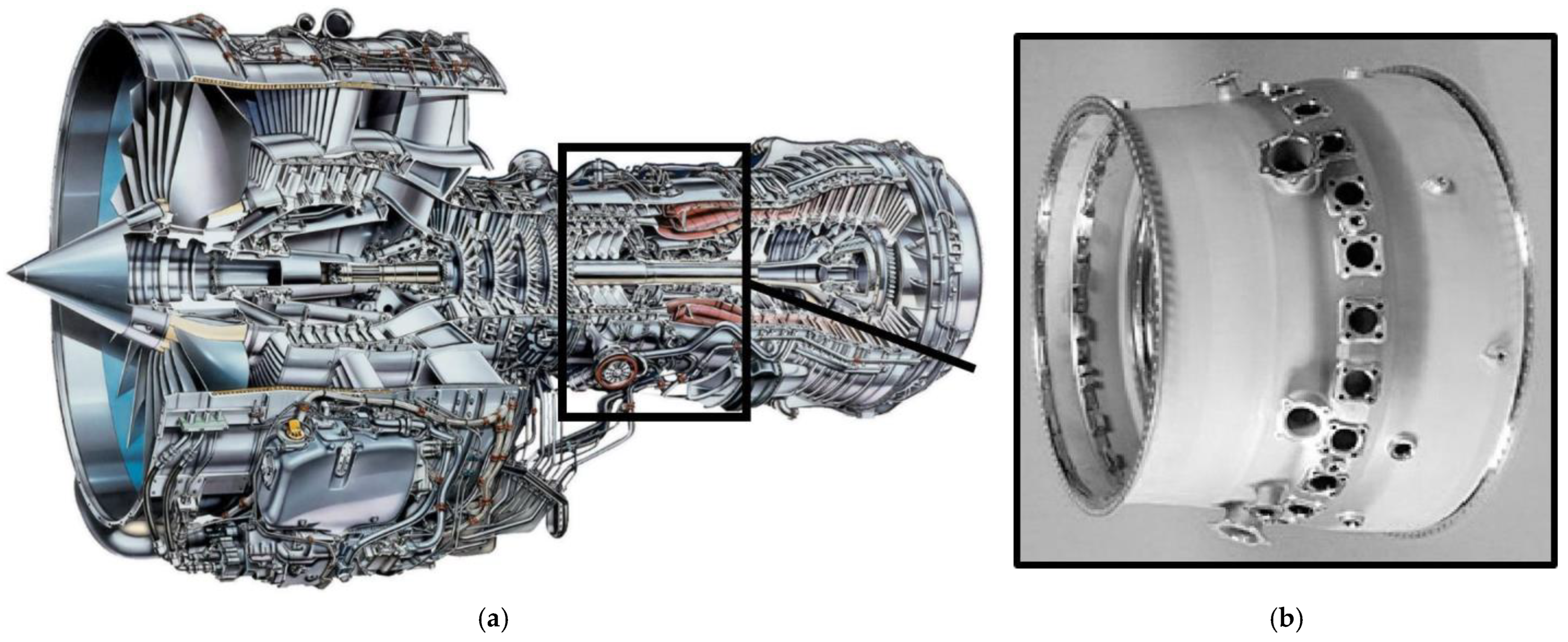
The subject matter of the article presents part of the research carried out as part of the robotization of the manufacturing processes of aircraft engine components. The paper concerns the diffuser of the V2500 engine (
Figure 1a). It is a two-shaft high-bypass turbofan engine. It is produced by the International Aero Engines consortium (East Hartford, CT, USA), which was established in 1983. The V2500 unit powers the Airbus A320 and McDonnell Douglas MD-90 aircraft. The engine was certified by the FAA in 1988. As part of its activities, Prat & Wittney, Rzeszów S.A., which is part of UTC, performs technological operations consisting of processing diffuser castings of the V2500 engine (
Figure 1b). One of the many technological operations is edge deburring.
In the process of making the diffuser, there are a number of edges that require deburring, which is done manually. Manual processing is due to the fact that there are elements with a shape that varies randomly to a limited extent. It is caused by the applied precision casting technology, characterized by the variable geometry of the workpiece depending on the accuracy of the casting molds and the phenomenon of shrinkage during solidification. This generates difficulties with precisely defining the shape, which in turn results in the need to use manual finishing. This fact introduces a high risk of defective elements related to the presence of human factors (error, fatigue, and stress).
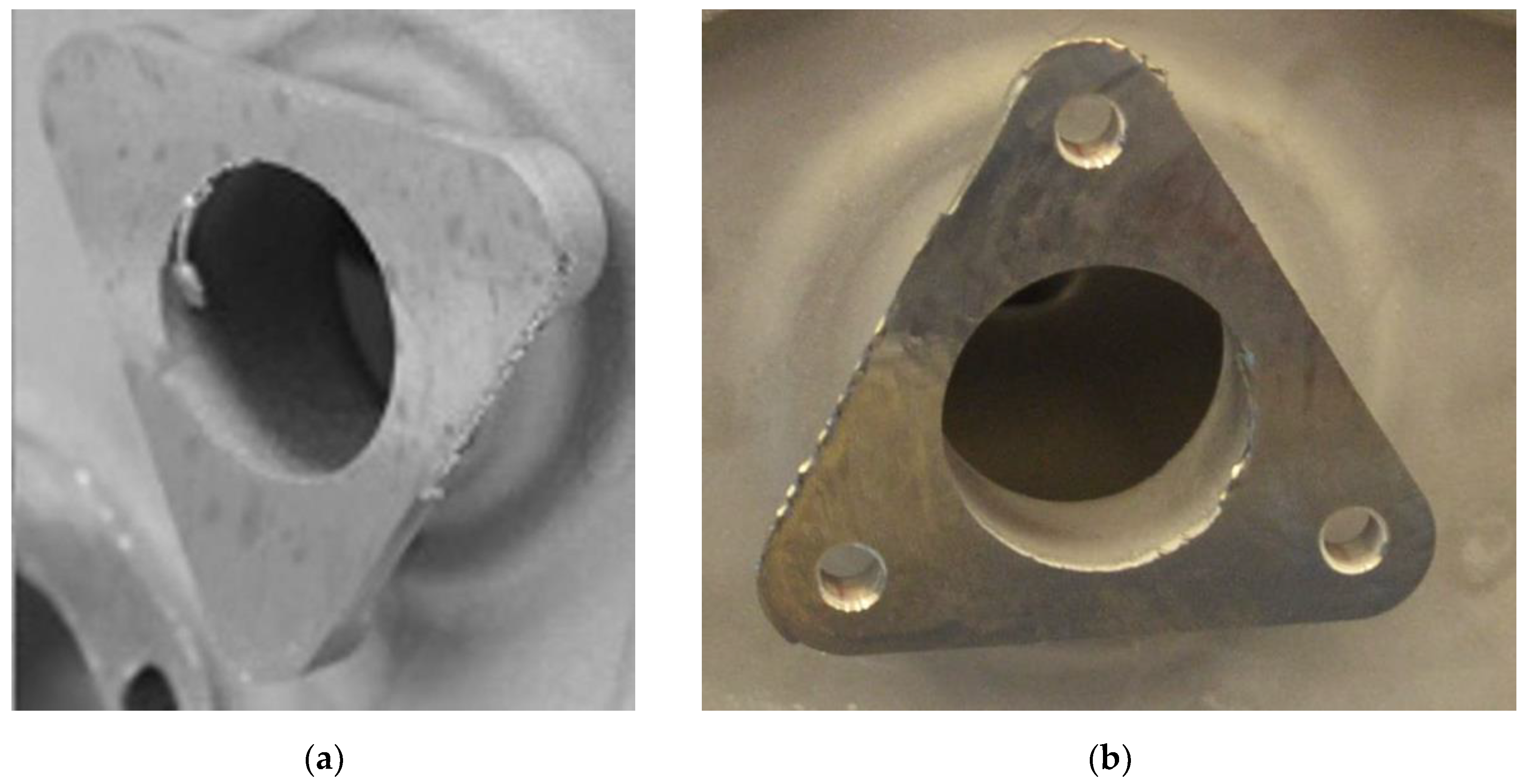
There are nine types of shapes that can be deburred in the diffuser of the V2500 engine. The triangular boss shown in
Figure 2 has been selected as an example.
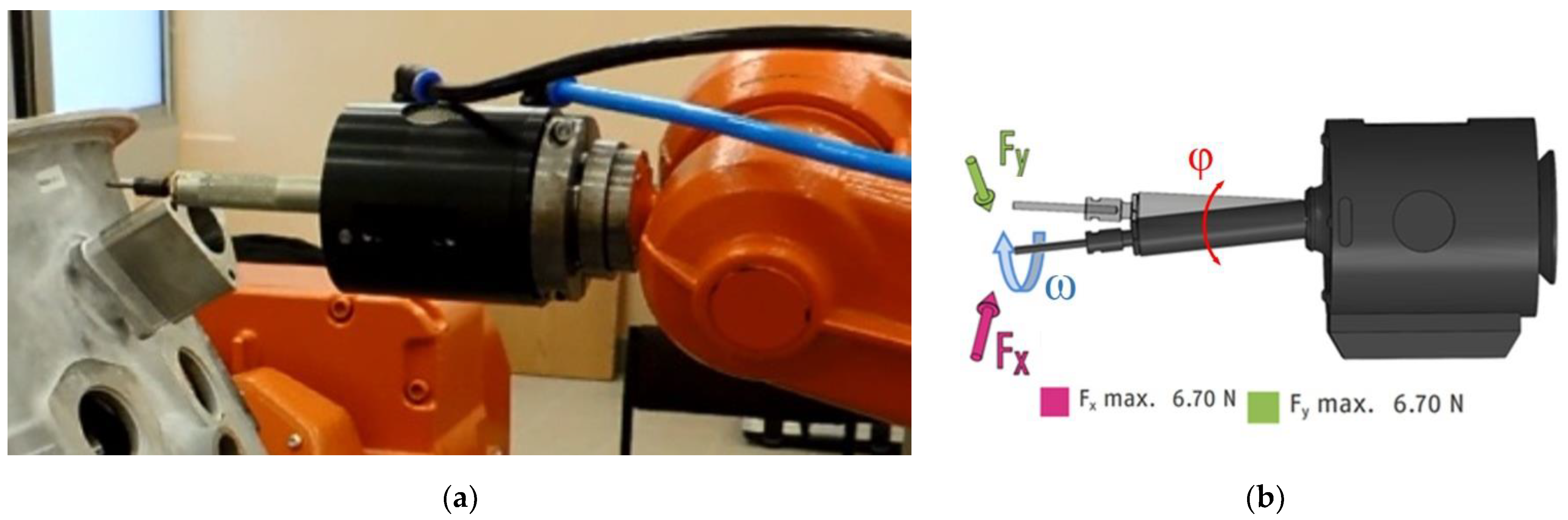
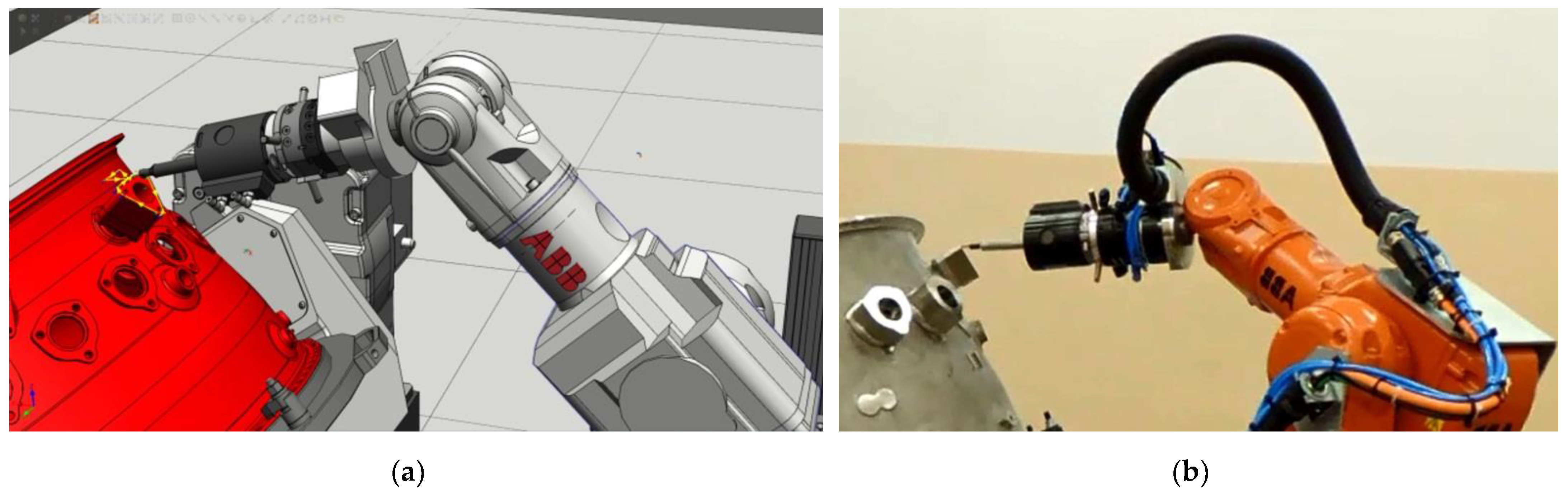
Control of deburring at several selected points is carried out using optical methods. The vast majority of the quality of the operations performed is carried out visually by a quality control employee. The purpose of quality control is to eliminate workpieces with sharp edges, notches, or cuts. It is obvious that the presence of surface notches reduces the fatigue life of the workpiece. As part of the work, a robotic station for deburring edges (
Figure 3a), using a pneumatic tool (
Figure 3b), was proposed. The use of a pneumatic tool with progression of the feed force was dictated by the necessity to make chamfers with a small dimension of 0.1–0.5 mm.
The process is performed by the ABB IRB140 robot. The robot controller communicates digitally with the pressure setting system, cooperating with the FDB150 tool. The most important parameters of the FDB150 tool are the maximum speed of 65,000 rpm and the adjustment of forces in the range from 3.1 to 6.7 N depending on the pressure. The possible range of control pressures is programmed from 1.4 to 4.1 bar.
For the deburring process carried out, the FDB150 tool acts as a pneumatic spring to dampen the vibrations that occur during the deburring process. The spindle stiffness is pneumatically regulated by means of compressed air. The dependence of the force generated on the tool on the set pressure has been included by the manufacturer in the form of a chart in the documentation. These values were checked with a force gauge and a digital pressure regulator during the static test. A PNEUMAX 171E2N.T.D.0009 pressure regulator, with a range of 9 bar and a sensitivity of 0.01 bar, was used to apply pressure during the tests. The accuracy of the applied force obtained during static tests was 0.1 N. Tests of the accuracy of the applied force during the deburring process were not conducted. Testing during the process would require a multi-axis force and moment sensor mounted on the robot or workpiece.
Initial research work carried out with the use of a pneumatic tool allowed for the drawing of conclusions that effective control of the pressure change, and thus the tool/workpiece contact force, is impossible. This is because the machining is performed on parts of a workpiece of a complex shape. Since the amount of material removed is small, the tool moves at a high speed with low contact forces. The speed of movement of the TCP is so high that the response time of the system is greater than the necessity to change the inputs due to its complex shape. The compressibility of the air causes a delayed reaction of the tool, which in turn results in the suppression of rapid changes in the value of the force set by the robot controller. This fact generates the necessity to select the parameters of the machining process, i.e., to define the strategy of the movements, air pressure values, and thus the tool/workpiece contact force, and to determine the speed of the TCP.
3. Results and Discussion
The insensitivity of the machining system to shifts of the boss due to inaccuracies in the form and the phenomenon of solidification of the casting is ensured by the tool with pneumatic progression of the feed force, which is presented in
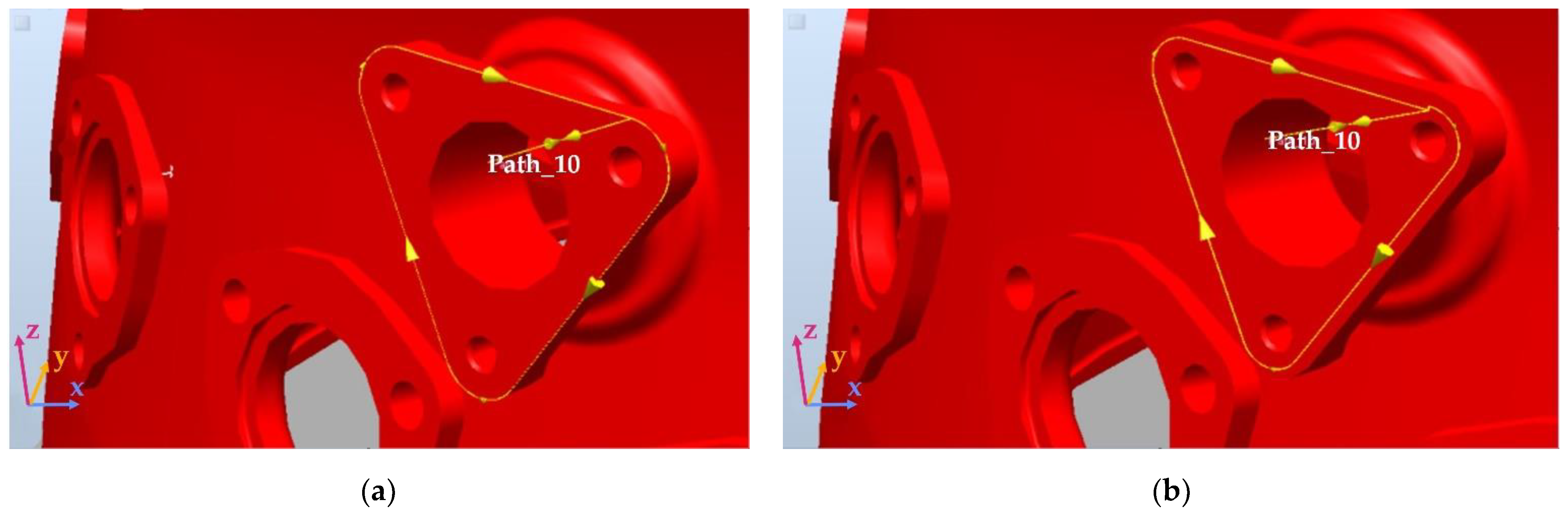
Figure 3b. The possibility of deviation of the spindle axis from the neutral position is within the range of ±5 mm, which completely ensures insensitivity to the limited inaccuracies of the machined surfaces and allows for the offset trajectory to be programmed. Assuming the maximum dispersion of the shape of the boss is at the level of ±2 mm, it is possible to design an offset trajectory. The offset trajectory was determined in relation to the nominal model and its value was adopted at the level of doff = 1.7 mm. The view of the nominal trajectory is shown in
Figure 4a, while the offset trajectory is shown in
Figure 4b.
In the classic approach to programming the robot’s movement, a fixed workpiece with its trajectory is used. In this case, it is necessary to change the angles of the joints of the robot in order to carry out the movement along complex shapes. The more complex the shape, the greater the velocity and acceleration values in the joints. This causes large inaccuracies in the implementation of the set TCP speed. In machining processes, this results in a change, for example, in the width of the obturation performed. In order to ensure the smoothness of the surface and the absence of places with a significant fluctuation in the value of the material removed, the work was carried out using dependent MultiMove movements. They consist of the simultaneous movement of the workpiece and the tool. This allows the speed of movements in the robot joints to be reduced and the TCP speed to be implemented better, since the positioner movements help to implement the trajectory.
Figure 5a shows the modeling of triangular machining using the MultiMove function, while
Figure 5b shows the implementation of the modeled process.
In the initial period of research, two tool shapes were analyzed: end mill (HFC 0313.03.Z5 Lukas) and conical milling cutter (HFM 0307.03.Z7). In further parts of the work, the conical cutter was abandoned because there were problems with stabilizing the cutting process, and in particular with stabilizing the width of the chamfer.
3.1. Selection of Process Parameters Influencing the Width of Deburring
The development for a robotic technology of edge deburring with the use of a pneumatic rotary cutter should begin with the determination of two important parameters: the tool feed rate and the tool/workpiece contact force. The rotational speed of the tool is constant and results from the type of pneumatic tool used. After selecting the above-mentioned parameters or several of their values, the repeatability of the process should be checked and the parameters for its initiation selected.
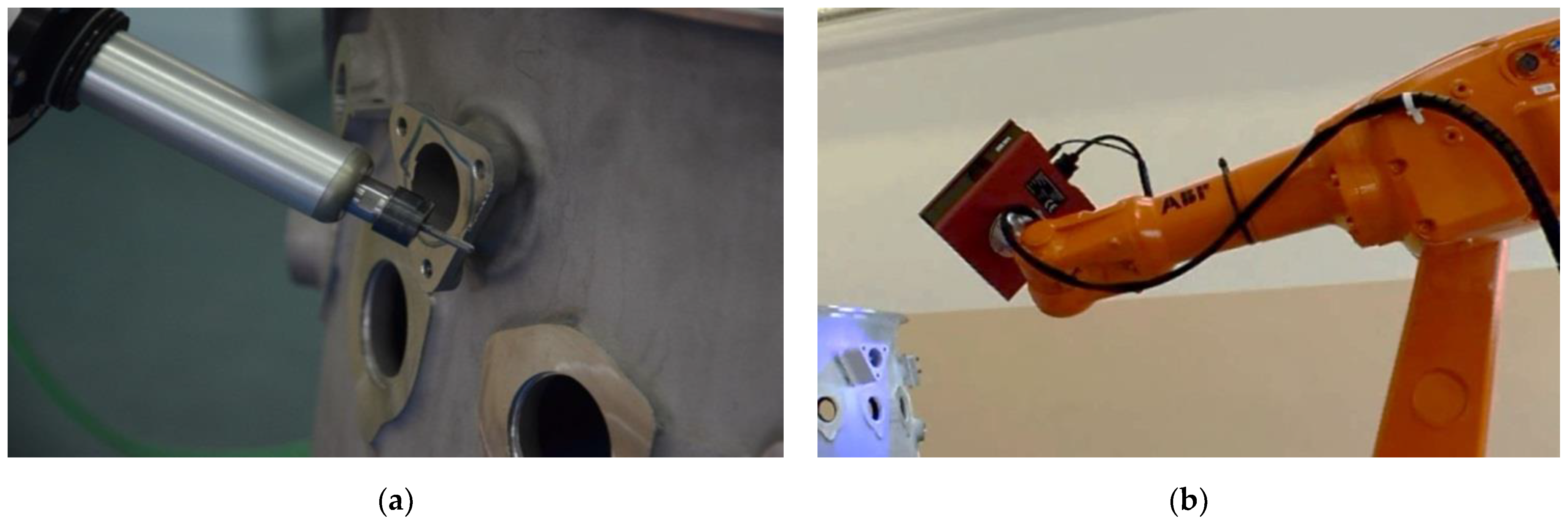
The selection of process parameters is related to the necessity to perform a very large number of measurements. Therefore a robotic automatic measuring system was used, consisting of the IRB1600 robot, a 3D scanner, and the ATOS Professional software (
Figure 6b). Control measurement points were proposed in places where the greatest inaccuracy of the embedding was expected.
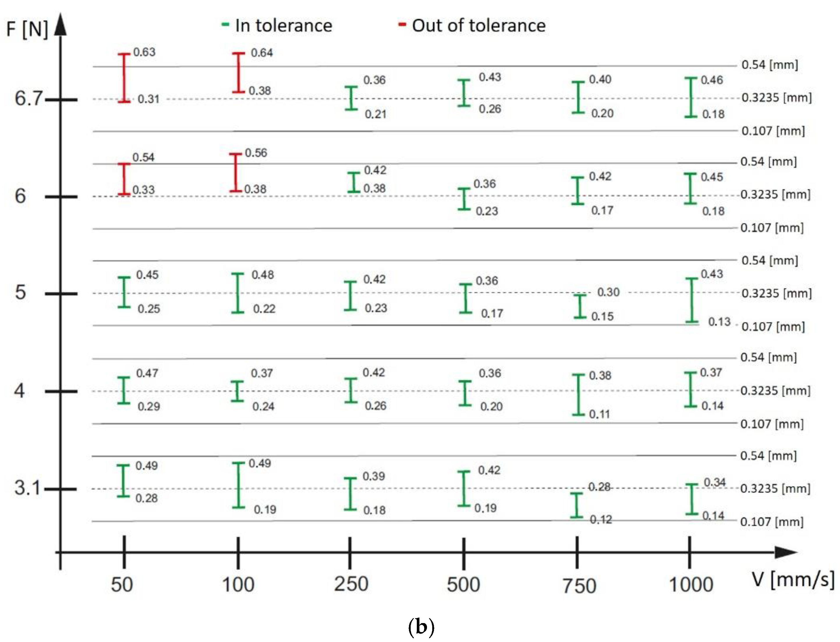
The diagram in
Figure 7b summarizes the values of the chamfer width spread for different robot TCP speeds: 50, 100, 250, 500, 750, and 1000 mm/s. The diagram was prepared for the forces 3.1, 4, 5, 6, and 6.7 N. Values of parameters meeting the imposed limitations resulting from the width of the chamfer being implemented are marked in green. An example of the result of the deburring process is shown in
Figure 6a.
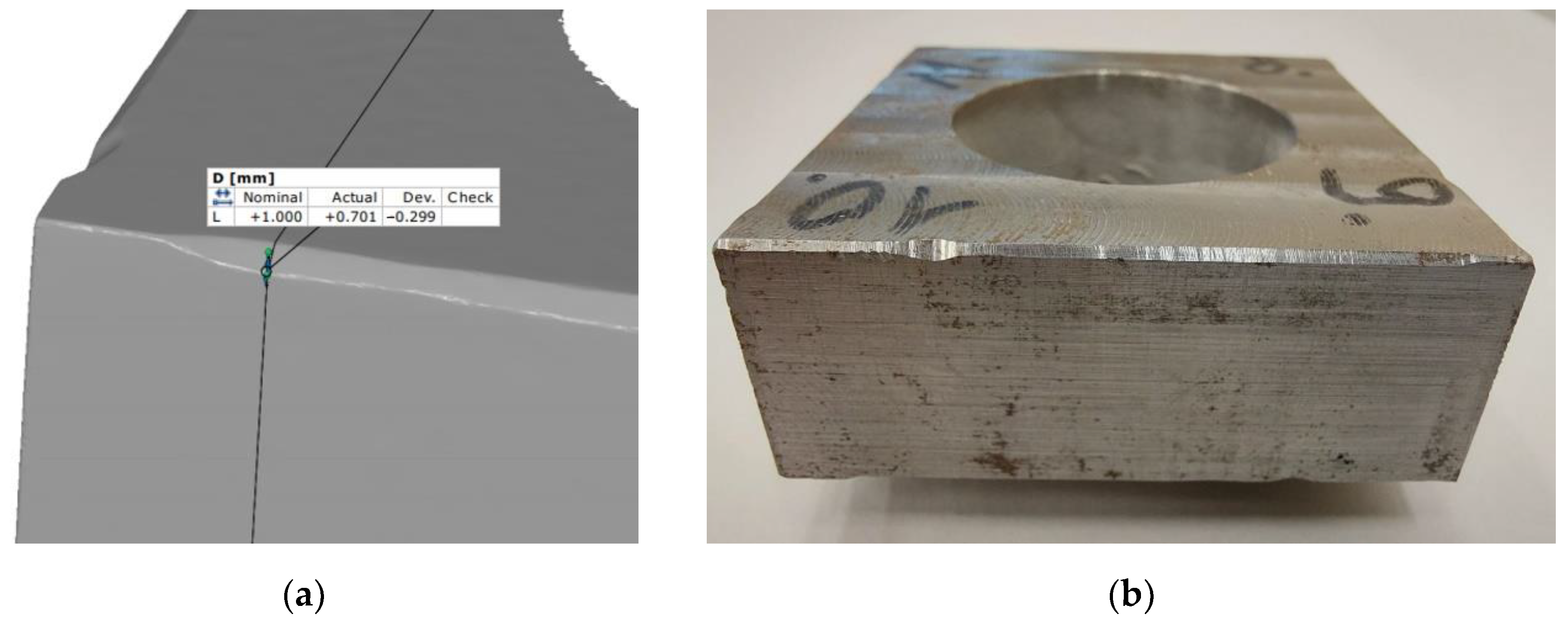
A total of 360 measurement points were used to prepare the graph presented in
Figure 7b. An exemplary measurement report for one tool/workpiece contact force value and one set TCP movement speed is shown in
Figure 7a.
The analysis of
Figure 7b allows for the conclusion that there is a wide range of process parameters, i.e., contact forces and TCP movement speeds, which, at a given nominal tool speed, ensure edge deburring in accordance with the requirements defined in the documentation. In order to select from the set of parameters those that will ensure the best possible implementation of the process, the following optimization procedure described in [
26] was proposed.
3.2. Selection of Process Parameters at the Time of Its Initiation
During the machining process of steel samples by the manipulator at a constant speed of movement of the tool and constant pressure of the spindle in the area of starting the machining, the process is disturbed. Air compressibility, proportional to the set force, requires time to stabilize the process. This results in excessive or insufficient material removal. It takes until the spindle operating parameters are established. The research work aims to register changes and to experimentally select the spindle pressure force or change the tool feed rate during milling, so that the machining is uniform along the entire length of the sample edge. An example of a disturbed chamfer width is presented in
Figure 8.
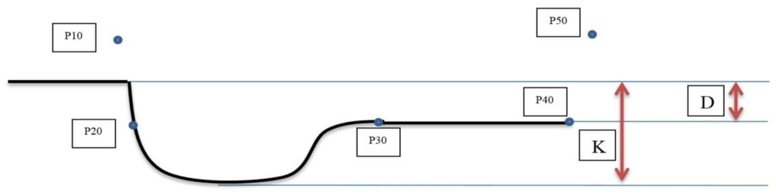
A number of Inconel 718 steel samples were prepared for the research. The experiment was carried out in such a way that the robot performs a chamfer at an angle of 45°, for which a path consisting of five points was programmed. Point P10 is the start of movement. Point P20 defines the chamfer depth. Point P30 is approximately 12 mm from point P20 and defines the chamfer depth. It is at the point where the disturbance ends. Although the distance between the points P20 and P30 is not exactly 12 mm in every case, this average value was adopted based on experience. Point P40 defines the end of the milling process, and P50 is the end point outside the workpiece. The shape of the adopted path is shown in
Figure 9.
Additionally, the dimensions K and D, marked in
Figure 9, were introduced, which are, respectively, the depth of machining when starting the cutting process (K), and the nominal assumed depth of material removal (D). As part of the research, parameters such as the spindle feed force between the points P20 and P30 or the change in the speed of the robot’s movement are looked for so that the depth of machining along the entire length is D. In the first step, based on the diagram in
Figure 7b, the values of the robot’s TCP force and speed were selected, for which the suboptimal parameters for the beginning of the cutting process were selected. The selected values are summarized in
Table 1.
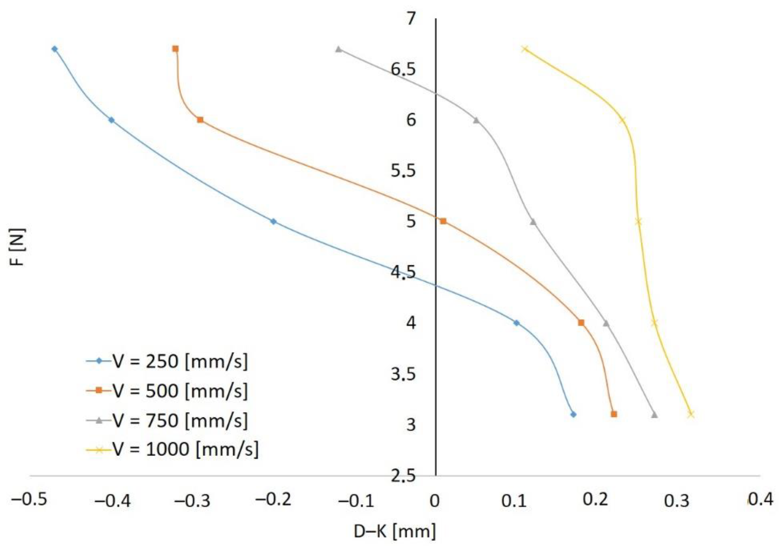
The next step was to determine the D–K difference (
Figure 9), assuming a constant speed and changing the contact forces within the range 3.1–6.7 N. The test results for the velocity values of 250, 500, 750, and 1000 mm/s are presented in
Figure 10. The value of the force at a given speed for the correct implementation of the machining process initiation is obtained in the case of a zero value of the difference D–K. At the speed of 1000 mm/s, this situation does not occur. The other tests show that it would be reasonable to use force changes at the entrance at TCP speeds of 250 and 500 mm/s. In these cases, the zero value of D–K is in the half of the available force adjustment range, while at the speed of 750 mm/s, the value of D–K is equal to zero when the force is close to the maximum value. It is not possible to increase it.
For the three correct values resulting from the zero D–K difference (
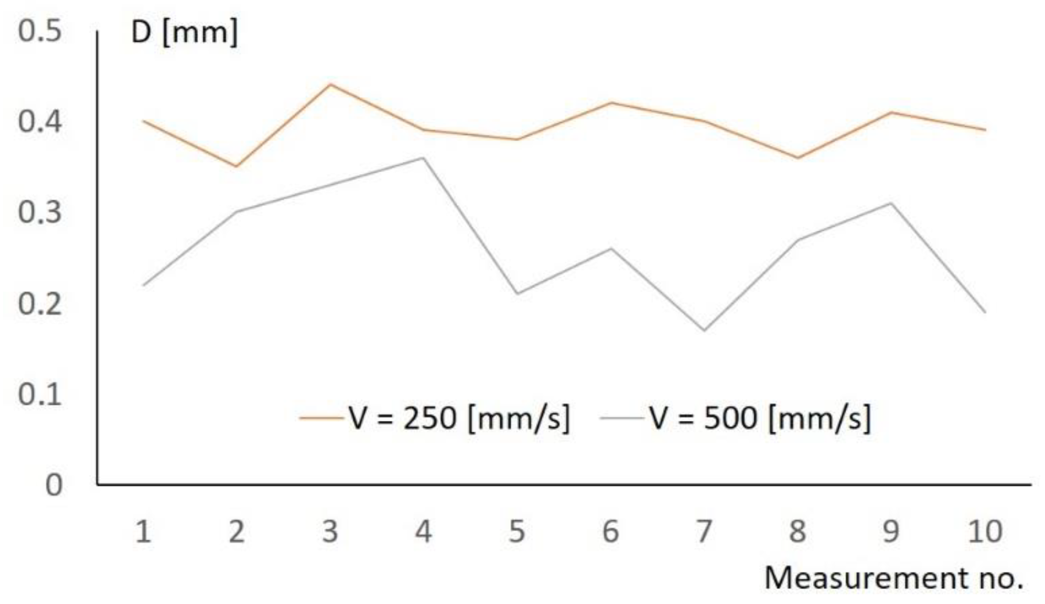
Figure 10), a sensitivity test of the process parameters was carried out, shown in
Figure 11. The sensitivity of the process was tested for the parameter D. The tests were carried out for the entry parameters V = 250 mm/s, F = 4.5 N and V = 500 mm/s, F = 5 N.
As can be seen at low feed rates due to the longer time of pressure stabilization, and therefore also the force, the best repeatability of the process is obtained. This conclusion prompted the performance of the analysis, the results of which are presented in
Figure 12. It concerned the study of the impact of changes in the speed of starting the process at a constant tool/workpiece contact force.
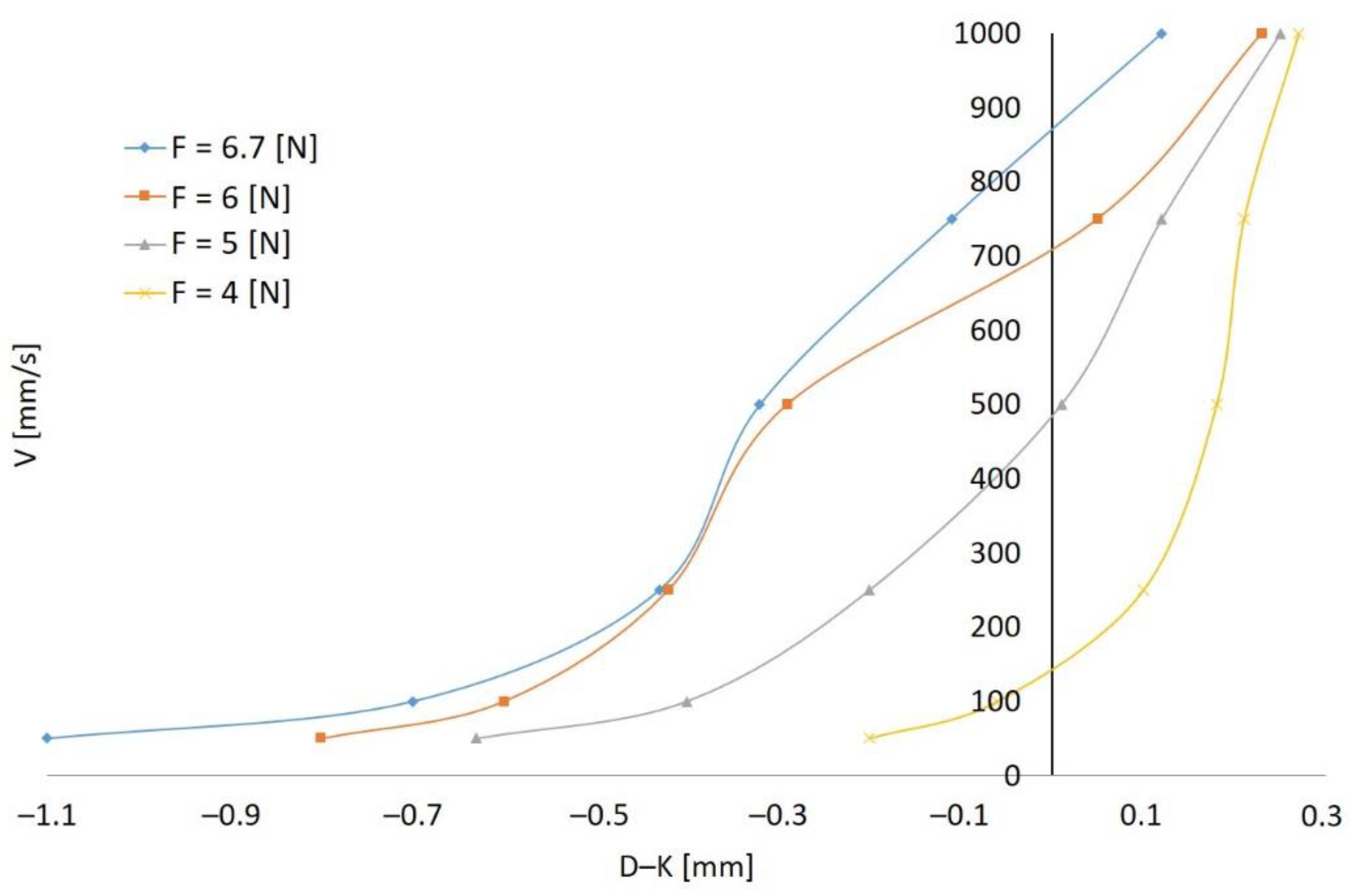
Figure 12 shows the values of the starting speed of the machining process with the assumed constant value of the contact force, and the value of the TCP movement speed was converted. That is, unlike in
Figure 10, where the movement speed was constant, and the variable force was the parameter influencing the chamfer size. As can be seen, a zero value of the difference D–K for four sets of force and velocity parameters is obtained. For the value of the force of 5 N and 6 N, it can be changed as it is not the limit value for the FDB150 tool used, which, in the event of the need for correction in production conditions, gives such an opportunity. Therefore, as parameters for the correct start of the deburring process when changing the tool feed rate parameter, the values V = 750 mm/s, F = 6 N and V = 500 mm/s, F = 5 N were selected. Similarly, as above, for the obtained process parameters with the zero value of the difference D–K, the stability of the obtained solution was tested in 10 trials, the results of which are presented in
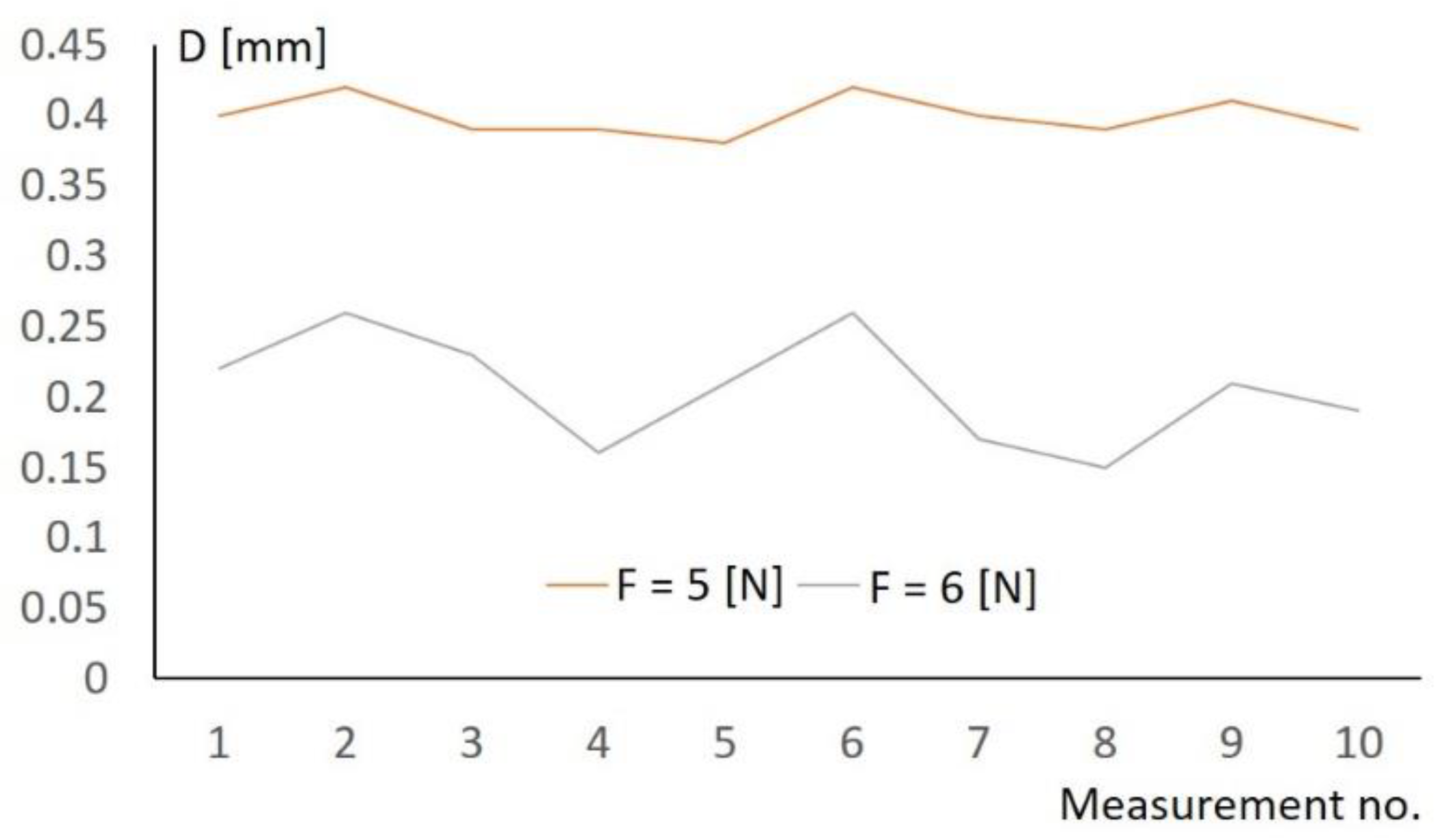
Figure 13. The tests were carried out for the entry parameters V = 750 mm/s, F = 6 N and V = 500 mm/s, F = 5 N.
Figure 13 shows that better repeatability of cutting with a pneumatic tool is obtained for a force value of 5 N. The results of the repeatability of the process were summarized on the basis of 10 tests. The obtained results of research on the impact of changes in force and tool feed rate on the width of the deburred chamfer allow for the following conclusions to be drawn: better results of stabilization of the chamfer width at the start of the process are obtained with changes in the value of the process start speed, and there is a force value for which the chamfer accuracy spread is at the level of 10% of the nominal value.
The problem presented in the paper concerns the optimization of two parameters, force and velocity, and the objective function contains one parameter that must be satisfied, and that is the difference of geometric parameters D–K must be 0. When the relation D–K = 0 is satisfied, the second parameter considered for optimization is the stability of the process. The stability of the process is shown in
Figure 11 and
Figure 13.
The tool with pneumatic force application works without an external feedback loop. The process is very fast. The forces of 4–6.7 N are very small. The value of the force was measured for given pressures in a static way. In the experiment, the set force has a large inaccuracy due to the compressibility of the air and the speed of the pressure regulator. Therefore, only four levels of force values (4, 5, 6, and 6.7 N) were digitized in the study. With such small forces, the amount of material removed is small, therefore the speed of movement of the TCP was assumed to be 50, 100, 250, 500, 750, and 1000 mm/s. Due to the failure to meet the criterion D–K = 0 for large forces of 6.7 N, the values of velocity 50 and 100 were rejected. For a force of 6 N, the values of 50, 100, and 250 were rejected. For a force of 5 N, the value of velocity was 1000. In addition, under these operating conditions, high tool wear was noted.
All possible parameters are summarized in
Table 1. This is a set of data including 17 items for which the combination of parameters for which the D–K relation is equal to 0 is to be indicated. Since the amount of input data is small, it is possible to analyze all possible combinations. Therefore, the optimization methods known from the literature were not applied. Thus, seven combinations of contact force and velocity parameters for which D–K = 0 were obtained. The D–K = 0 relationship satisfies the imposed technological parameters. In the following part, for the seven pairs of parameters, one was selected for which in 10 consecutive attempts to start machining, the maximum error resulting from the difference D–K had the smallest relative value.
In summary, the dimensionality of the task is so small that the process of selecting a suboptimal solution does not require the use of complex optimization methods. At the same time, it is transparent and simple in perception, by which it has high application value.
4. Conclusions
The research results presented in the paper provided information on the accuracy with which edge deburring with the use of flexible pneumatic tools can be performed. Therefore, as the most difficult element of deburring is its initiation, a procedure was proposed that allowed for the indication of a set of process parameters that ensured the implementation of the process in accordance with the requirements defined in the documentation. The proposed solution is of an engineering nature and is not a classic search for an optimal solution. The advantage of the proposed solution is simplicity, which ensures correct implementation of deburring, which is very important from the point of view of an industrial application.
The obtained results of the research work allow for the conclusion that the best results of stabilization of the chamfer width at the start of the process are obtained with changes in the value of the process start velocity parameter. It is not advisable to look for the possibility of influencing the machining volume during the start by changing the value of the tool/workpiece contact force. This conclusion is universal.
It should be noted that the obtained results relate to Inconel 718 and the HFC 0313.03.25 tool and they are not universal. The authors propose a procedure for carrying out work allowing for the selection of suboptimal process parameters. In the analyzed case, these parameters are the speed of movement of the characteristic point and the tool/workpiece contact force.
The obtained results were used during the construction of a robotic station at Prat & Wittney S.A. in Rzeszow.


 ,
, 


