Article

A Novel Airspace Planning Algorithm for Cooperative Target Localization

1
College of IoT Engineering, Hohai University, Changzhou 213022, China
2
Key Laboratory of National Airspace Technology, Beijing 100085, China
3
State Key Laboratory of Air Traffic Management System and Technology, Nanjing 210007, China
*
Author to whom correspondence should be addressed.
Electronics 2022, 11(18), 2950; https://doi.org/10.3390/electronics11182950
Submission received: 5 August 2022 / Revised: 8 September 2022 / Accepted: 14 September 2022 / Published: 17 September 2022
(This article belongs to the Special Issue Modelling, Control and Emerging Application for Unmanned Vehicles)

Abstract

:
With the development of modern electromagnetic stealth technology and ARM, traditional active radar detection cannot accomplish its detection mission, limited by its ability. Relying on such superior advantages such as imperceptibility, anti-electromagnetic interference and electromagnetic stealth, passive transducers are playing an indispensable and significant role in situation awareness. While, in addition to different passive transducer localization modes and solutions of target’s location, the reasonable planning and optimal layout of passive transducers’ location are other major factors affecting the precision of localization. Planning an optimal airspace for passive transducers is the key problem to improve the monitoring efficiency. This paper proposes the optimal layout algorithm for the cooperative platform in the space based on the geometrical relationship of cooperative localization. For example, the principle of direction location in traditional methods is simple: only two passive sensors can work, but the location accuracy of long-distance targets is low. At the same time, TDOA (Time Difference Of Arrival) location has high accuracy and good stability, but it needs at least three passive sensors to work together, which requires the most resources. In this paper, a platform optimization layout algorithm based on direction and TDOA hybrid positioning is proposed. Compared with direction positioning, it improves the long-distance positioning accuracy, reduces the number of sensors required for TDOA positioning, and reduces the resource occupancy rate. However, the TDOA positioning data mixed with direction positioning data inevitably leads to the decline of overall accuracy. In order to solve these difficulties, the weighted least square method is used to optimize the accuracy. The simulation shows that, within the designated target airspace, the optimal action airspace can be generated automatically based on the platforms’ cooperation mode. If there is no resource limitation, the airspace planning based on TDOA positioning has the highest accuracy for the target. However, in practical application, considering the resource limitation, the hybrid positioning of direction and TDOA can also meet the requirements of high accuracy and high stability. The average error is reduced by more than 45% compared with direction positioning, and the airspace occupancy is reduced by more than 30% compared with TDOA positioning. The goal of minimizing the scope of platform airspace planning is realized.

1. Introduction

Accompanied with constant development of modern electromagnetic stealth technology and ARM (anti-radiation missile) technology are serious threats on traditional active radar detection. Relying on such superior advantages such as imperceptibility, anti-electromagnetic interference and electromagnetic stealth, passive transducers are playing an indispensable and significant role in improving defensive systems’ viability in electronic warfare, thus generating greater concerns. With the development of data chain technology, through which passive transducer platform realizes network-based organization and application, multiple passive transducers, therefore, construct the network-based cooperative awareness system and obtain better perceptibility. Correspondingly, at present, it has become an indispensable approach to apply passive transducers’ cooperative awareness in shared tactics.
Passive transducers detect the electromagnetic signals sent from the target and then distribute signals, DOA (direction of arrival) or arrival time within the network through data chain. Afterwards, collaboration platforms analyze and solve the information detected by the platform and remote information received through data chain in a cooperative way so as to confirm the target’s position and recognize its attributes.
According to passive transducers’ working mode and localization principle, passive localization can be classified into AOA (Angle of Arrival) localization [1,2,3,4,5], TDOA localization [6,7] and AOA-TDOA localization [8,9]. In terms of direction localization, the target’s location is figured out via the algorithm by confirming the target’s azimuth angle and pitching angle. Compared with other positions, the information about the angles is quite reliable and easily obtainable, which makes direction localization technology a relatively mature passive transducer localization [1,2,3]. However, considering the small amplitude of variation of the target’s angles in a long distance, direction localization has huge errors, which requires multi-platform cross localization [3,4,5]. TDOA displays the highest precision compared with other passive localization approaches. It is also applied in multi-platform passive localization at the earliest time [6]. The current major TDOA algorithms include Taylor series expansion [7], Chan algorithm [8], AML [9], SX and SI algorithm [10], Fang algorithm [11], Bias Sub and Bias Red algorithm [12], etc. Nevertheless, TDOA algorithm’s computing efficiency is restricted by target solution equation. Additionally, TDOA’s passive localization entails a number of platforms. These factors result in more complexity and affect precision. Hence, Li Cong proposes the combination of TDOA and AOA [13,14,15,16] so as to simplify the localization algorithm and reduce the number of observation stations to a large degree.
In addition to different passive transducer localization modes and solutions of target’s location, reasonable planning and optimal layout of passive transducer’s location is another major factor affecting the precision of localization. Particularly, under the circumstance where passive transducers are loaded on the mobile platform, apart from the solution of target’s location, the mobile platform’s planning in the maneuvering airspace also exerts great effects on the precision of the target’s localization. Based on the different targets and shapes of planned airspace, airspace planning is generally classified into route planning [17,18,19,20,21,22] and region planning [23,24,25,26,27,28,29]. The former one performs the optimal planning of the aircraft’s route and tracks by clarifying the starting point and restricting the terminal destination on the basis of the aircraft’s overload capacity and GPS localization [18,20] and applying dynamic planning [19], cooperative planning [17,21], etc. The latter one conducts graphical or three-dimensional planning of the airspace by confirming the airspace and delimiting restrictions according to the radar’s location and range of detection [23,24] on the basis of the application context and purpose, such as cooperative monitoring [24,25,26] or joint air defense [27,28,29,30]. At present, solutions of airspace planning concerning cooperative localization platforms are still at the early stage.
To solve the problem that Multi UAV airspace planning is difficult to coordinate, as well as airspace planning is disconnected from mission requirements, the paper analyzes the geometrical relationship of cooperative localization, designs the optimal layout algorithm for the cooperative platform in the space, and confirms the transducer platform’s valid range of cooperative localization, thus planning transducer platform’s searching route based on the task zone. The functional process of the proposed cooperative localization algorithm for passive transducers, including the shape of cooperative localization zone and optimal planning algorithm of three different working mode, as Figure 1.

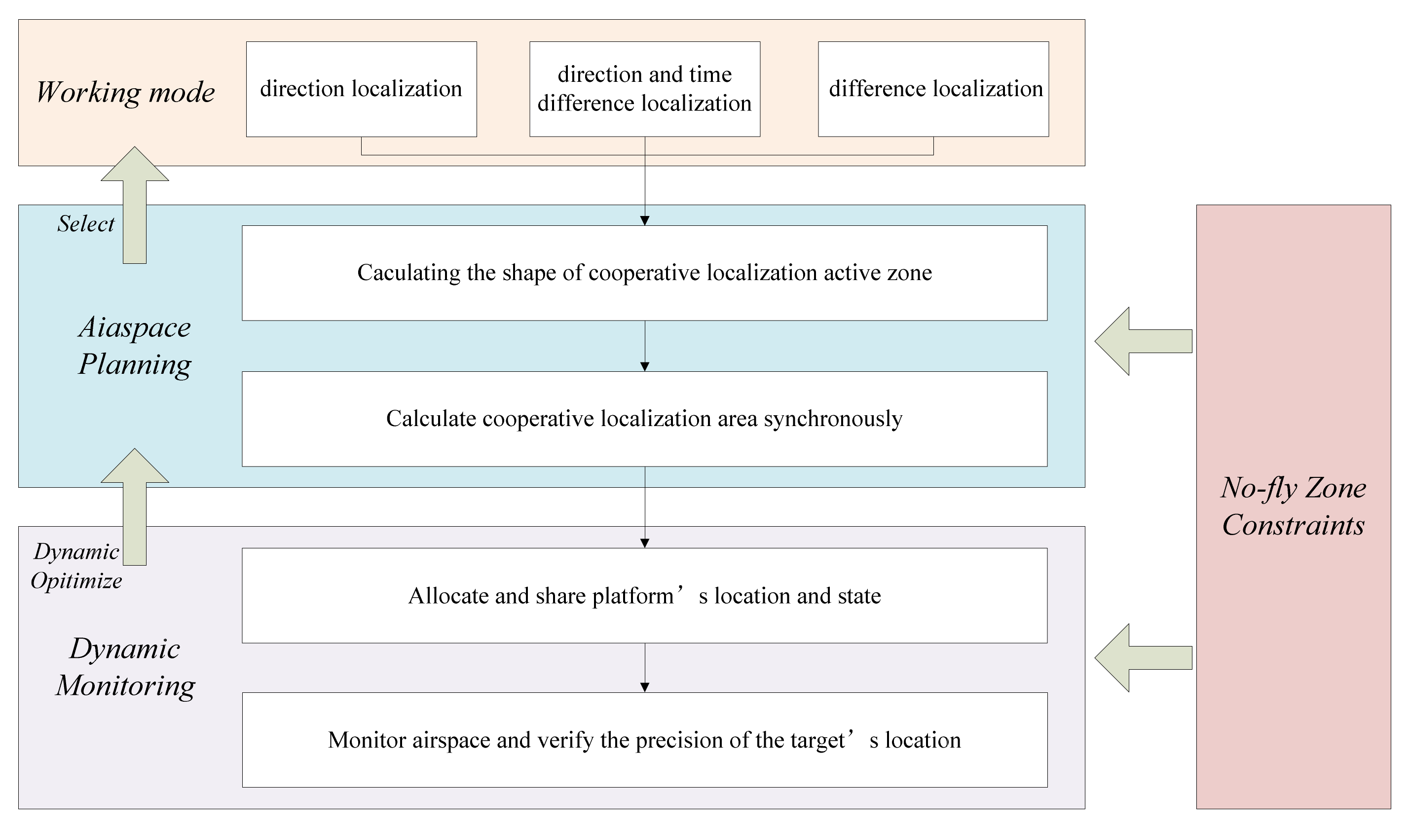
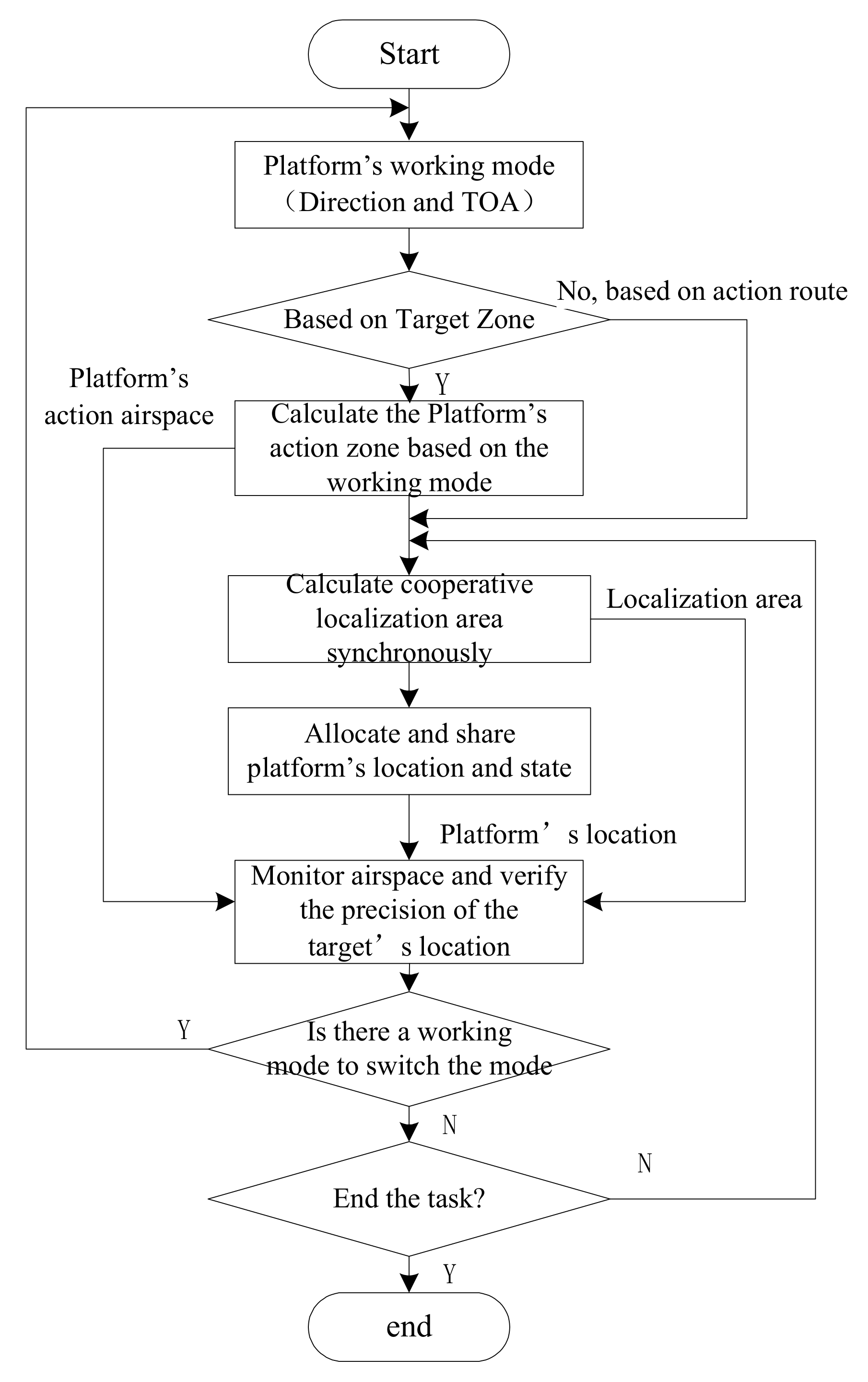
2. Airspace Planning in Multi-Platform Cooperative Localization

Multiple sensors cooperate to perform target positioning. The carrying platform is divided into two types: directional and omni-directional. According to different cooperative positioning methods, the spatial planning mathematical model is established. Based on the advantages and disadvantages of directional positioning and TDOA hybrid positioning and the limitations of the formed positioning area, the shape of the positioning area of directional and TDOA hybrid positioning is studied. In practical application, sensors and planned airspace should be comprehensively selected according to the location of the airport, target airspace and airspace operation.

2.1. Shape of Direction Localization Zone

Suppose: the distance between Platforms A and B is D; the antennas point at active target T, shown in Figure 2. The angle of direction α 1 and α 2 . Then, the distance between the target and the two targets is, respectively: R 1 = sin α 1 sin α 1 + α 2 · D and R 2 = sin α 2 sin α 1 + α 2 · D . The resolution cell, precision of localization and non-synchronous errors are all related to the intersection angle of the two platforms’ antennas, γ . In addition, when γ = π 2 , 3 π 2 , the values are minimal; when γ = 0 , π , the values are infinitely great. Hence, γ must be controlled within a certain range so as to achieve tactical goals. Generally, the cooperative localization zone is valid when γ = 30 ° ~ 150 ° . In direction localization, in the circle with the diameter AB ¯ , any intersection angle γ , formed by the intersection points of the two platforms is 90 ° . Then, the circle is regarded as the optimal intersection circle. The track formed by the points with the intersection angle γ = 30 ° is a circle with AB as the chord. The opposite angle of the cyclic quadrilateral is complementary, reaching 150 ° . Similarly, the same circle can be formed below AB. The “XOR” zone of the two circles is correctly the coordinative localization zone that meets the condition, γ = 30 ° ~ 150 ° . The central point of the localization zone, Q forms an equilateral triangle with A and B.
Direction positioning only depends on two mobile platforms to achieve a large range of target positioning, but there will be a small detection blind area between the two platforms. In practical application, there will often be more restrictions, and the existence of detection blind area will greatly affect the application requirements.

2.2. Shape of Time Difference Localization Zone

Time difference localization uses three or more passive transducers to confirm the distance difference between the target and any two transducers. Every two transducers obtain a bunch of hyperbolic curves. Then, the target’ location is confirmed via the intersection point of different hyperbolic curves. The main restrictions on the measurement of the range of time difference localization include: ① In terms of the intersection angle, γ , of two groups of hyperbolic curves, the minimal value should ensure that the target’s location achieves tactical goals; ② In terms of passive transducers’ maximal perceived distance, R m a x , the target of cooperative localization must be within the overlapped range perceived by multiple transducers.
Suppose: Platforms A, B and C are arranged in a linear way. Two groups of hyperbolic curves, AB and BC are thus formed. According to the features of hyperbolic curves, the tangent line of any point, T, on the curve, T G 1 is the bisector of A T B of AB, while T G 2 is the bisector of B T C of BC, as shown in Figure 3a). The intersection angle of T G 1   and   T G 2 is the intersection angle of two hyperbolic curves marked as γ . It is evident that A T C = 2 γ . When γ is a constant value, the localization zone of ABC is the circle with AC as the chord. The angle of circumference is 2 . The coordinate of the circle center is 0 , D 2 tg 2 γ ; radius = D 2 sin 2 γ . Under this condition, the localization zone is irrelevant to B’s location, i.e., B can be at any arbitrary place along AC segment.
If A, B and C form a triangle, T G 1 is the tangent line of AB and the bisector of A T B , while T G 2 is the tangent line of BC and the bisector of B T C , shown in Figure 3b. The intersection angle of T G 1   and   T G 2 is the intersection angle γ of the hyperbolic curve. When γ is a constant value, the localization zone of ABC is still a circle with AC as the chord. The coordinate of the circle center is 0 , D 2 tg 2 γ ; radius r = D 2 sin 2 γ . The localization zone is restricted by R m a x , i.e., related to B’s location. It will be discussed below.
According to Figure 4a,b moves below A C . A C = D . It is the long side. A B C = θ . A circle is drawn with A C as the chord and the angle of circumference, 2 γ . Then,
A P ¯ = D sin 2 γ R m a x
The change of B’s location is reflected by θ . Besides, BQ ¯ R m a x
BQ ¯ = B O ¯ + O O ¯ + O Q ¯ = D 2 1 tg γ + 1 tg θ / 2 ,   i . e . ,
D 2 1 tg γ + 1 tg θ / 2 D sin 2 γ
It can be solved, tg θ 2 ctg γ
i . e . ,   π 2 γ θ π
It can thus be seen that B’s location within the range π 2 γ θ π exerts no influences on time difference localization. To achieve tactical goals, 2 γ = 30 ° ~ 150 ° . According to symmetry of hyperbolic curves, provided that B moves to AC, there is the same localization zone below the base line AC, shown in Figure 4b. The center of the localization zone O constitutes an isosceles triangle with Platforms A and C (long side).
TDOA location requires at least three mobile platforms, occupying the most resources, so it has the highest accuracy and the best stability, but it has great defects in the detection range. When the three platforms are on the same straight line, there is a detection blind area in the same direction positioning. When the three platforms are not on the same straight line, although the detection blind area disappears, the detection range on one side is reduced, which has no advantage over the direction positioning in the positioning range.

2.3. Shape of Direction and Time Difference Localization Zone

(1)
Weighted least square method.
In 3D environment let N Mobile platforms S i x i , y i , z i i = 1 , 2 , , N . The coordinates of the target are T x T , y T , z T . A set of targets can be obtained by measurement to reach S 1 and S n , time difference data between τ i n , The angle information can be obtained by measuring the azimuth and pitch angle of the target reaching the two observation stations ( α i , β i ).
According to the above information, the vector model of the measured quantity can be listed:
e ^ = e + ε
e = α 1 , β 1 , α 2 , β 2 , τ 12 , α N , β N , τ i n T is the real time difference value and angle value data, e ^ = α 1 ^ , β 1 ^ , α 2 ^ , β 2 ^ , τ 12 ^ , α N ^ , β N ^ , τ i n ^ T is the measured value data of TDOA and angle with error, ε = δ 1 , γ 1 , δ 2 , γ 2 , σ 1.2 , , δ N , γ N , σ i n T is the error of the measured quantity, and its covariance matrix is Q.
By studying the geometric relationship between the target and the mobile platform, the following relationship can be obtained
T S i = r i · b i
where b i is the unit direction vector between the target and the observation station. The least square estimation of the target position can be obtained by calculating the formula
T ^ = P ^ P ^ T 1 P ^ H ^
H = P T T , P = G 1     2 b 2 b 1     G 2     2 b 3 b 1     2 b N b 1     G N
In order to improve the positioning accuracy, the error affecting the matrix P in the actual environment needs to be considered. At this time, the positioning model can be expressed as
H ^ + r = P ^ T + E T
It can be obtained by Taylor expansion and sorting
H e ^ = P T e ^ T L ε
where the expression of L is as follows
L = L a 1 0 0 r 1 b 2 T L b 1 r 2 b 1 T b 2 b 1 T b 1 0 0 0 0 0 0 0 0 r 1 b N T L b 1 0 0 0 0 0 r N b 1 T L b N b N b 1 T L a N 0
L a n = r n cos β ^ n 0 0 1
L b n = cos β ^ n sin α ^ n sin β ^ n cos α ^ n cos β ^ n cos α ^ n sin β ^ n sin α ^ n 0 cos β ^ n
L ε is the covariance matrix, and it is zero mean Gaussian noise with Q L = L Q L T . To sum up, the weighted least squares estimation of the target is
T ^ = P ^ W P ^ T 1 P ^ W H ^
W = Q L 1 is the weight matrix. Under the weighted least square algorithm, the positioning accuracy is improved no matter how many passive sensors are combined together, and so are the proportion transformation of direction positioning data and TDOA positioning data.
(2)
Drawing the shape of direction and TDOA mixed positioning area.
Suppose: the distance between Platforms A and Platform B is D. Platform A adopts omni-directional mode, while Platform B adopts directional searching mode. They conduct coordinative detection in the space. The time difference of electromagnetic signal’s arriving at A and B sent from the radiation source, T, is Δ t A B , and the distance is correspondingly Δ R = Δ t A B · C (C—the velocity of light). Then, the radiation source, T, should be on the hyperbolic curve whose long axis is Δ R   and   focal distance is D. In terms of B, the directional line’s azimuthal angle is α . The base line’s azimuthal angle is θ . The distance between the target and Platform B is:
ρ = D 2 Δ R 2 2 Δ R + D cos α θ
Suppose: the intersection angle of B’s directional line and hyperbolic curve (tangent line) is γ . To achieve tactical goals, γ = 30 ° ~ 150 ° . According to the two line’s intersection angle equation, it can be concluded:
x 1 2 + y 1 2 = 3 ( D 2 ) 2 2 ( Δ R 2 ) 2   ,   0 Δ R D
The formula reveals that target T is on the hyperbolic curve encircled by the circle when the time difference is a constant value.
Given that Δ R is valued continuously in the range 0 ~ D , the hyperbolic curve and circle can be drawn. After the connection of all intersection points of the hyperbolic curve and circle, the encircled part by the connected curve is precisely the range of valid localization in direction and time difference location, as shown in Figure 5.
For more convenient application, the connected curve can be decomposed into two symmetric circles, i.e.,
x 2 + ( y ± D 2 3 ) 2 = D 2 3
The equilateral triangle with side length, D, is inscribed with the circle of the localization zone.
Only two mobile platforms are needed for direction and TDOA positioning, which reduces the demand for computing power, has higher accuracy than direction positioning, has no detection blind area, has the widest detection range, and realizes the complementary advantages of direction positioning and TDOA positioning.

3. Optimal Platform Layout in Cooperative Localization

3.1. Optimal Platform Layout in Direction Localization

Based on the above analysis of shape of direction localization zone, the optimal platform layout in direction localization can be summarized as “triangle layout”. Suppose: the maximal distance of passive perception between Platforms A and B is R m a x . Cooperative direction localization is applied to conduct cooperative detection within the designated target zone (the radius of the circumcircle is r , r < 1 2 R m a x ). The optimal airspace of the platforms’ movement can be confirmed according to the target zone. The steps are as follows:
(1)
Draw a circumcircle concerning the target zone;
(2)
Draw a circle with the radius, 1 2 R m a x , that shares the same axis and vertex with the circumcircle;
(3)
Draw an equilateral triangle with the two circles’ center as the vertex, the radius as the side length and the same axis;
(4)
Connect two triangles’ base angles, as shown in Figure 6, to get the optimal movement airspace of Platforms A and B (Airspaces 4 and 5). Distance of the base line: r D 1 2 R m a x ;
(5)
Based on the zone’s center O, rotate the two triangles by an appropriate angle if conflicts with other airspace are found in airspace conflict detection so as to solve them.

3.2. Optimal Platform Layout in Time Difference Localization

Based on the above analysis of shape of time difference localization zone, the optimal platform layout in direction localization can be summarized as “triangle layout”. Suppose: the maximal distance of passive perception between Platforms A and B is R m a x . Cooperative time difference localization is applied to conduct cooperative detection within the designated target zone (the radius of the circumcircle is r , r < 1 2 R m a x ). The optimal airspace of the platforms’ movement can be confirmed according to the target zone. The steps are as follows:
(1)
Draw a circumcircle concerning the target zone;
(2)
Draw a circle with the radius, 1 2 R m a x , that shares the same axis and vertex with the circumcircle;
(3)
Draw two isosceles triangles with the circle center as the vertex, the radius as the side length, the same axis and the vertex angle, 4 γ .
(4)
Connect two triangles’ base angles, shown in Figure 7 to get the optimal movement airspace of Platforms A and C (Airspaces 4 and 6). The zone circled by 150 ° curve with AC as the chord is B’s movement zone (Airspace 5); distance of the base line: r D 1 2 R m a x ;
(5)
Based on the zone’s center O, rotate the two triangles by an appropriate angle if conflicts with other airspace are found in airspace conflict detection so as to solve them.
The biggest problem with the optimal platform layout under TDOA location is that there are many mobile platforms, and they occupy a large mobile area.

3.3. Optimal Platform Layout in Direction and Time Difference Localization

Based on the above analysis of shape of time difference localization zone, the optimal platform layout in time difference localization can be summarized as “triangle layout”. Suppose: the maximal distance of passive perception between Platforms A and B is R m a x . Cooperative time difference localization is applied to conduct cooperative detection within the designated target zone (the radius of the circumcircle is r , r < 1 2 R m a x ). The optimal airspace of the platforms’ movement can be confirmed according to the target zone. The steps are as follows:
(1)
Draw a circumstance circle concerning the target zone;
(2)
Draw a circle with the radius, 1 2 R m a x , that shares the same axis and vertex with the circumcircle;
(3)
Draw inscribed equilateral circles that share the vertex;
(4)
Connect two triangles’ base angles, shown in Figure 8 to get the optimal movement airspace of Platforms A and B (Airspaces 4 and 5). Distance of the base line: 3 r D 3 2 R m a x ;
(5)
Based on the zone’s center O, rotate the two triangles by an appropriate angle if conflicts with other airspace are found in airspace conflict detection so as to solve them.
The optimal platform layout under direction and TDOA positioning combines the advantages of the other two methods, reduces the number of mobile platforms, greatly reduces the moving area of the platform and ensures the accuracy and stability of detection.

4. Simulation Experiment Verification and Analysis

4.1. Simulation of Platform Airspace Planning in Cooperative Localization

Suppose: cooperative platforms A and B or A, B and C take off from the same airport and head for the designated zone to conduct detections. The target’s action zone is preliminarily set within the red dotted-line polygonal airspace, shown in Figure 9. The vertex coordinates of the target airspace are (149.334, 34.116), (88.167, 141.352), (−88.167, 141.352), (−135, 20), (−121.352, −68.167), (88.167, −101.352) and (149.334, 34.116). The coordinate of the airport’s location is (−10, −180). Each platform is mathematically described as follows. Mode means the working method; Linetype means the type of airspace; M means the spatial size of a group of four-dimensional coordinates; f means the working frequency of detection device in the airspace. The initial data are all primarily planned, which may change as instructed in operation.
Platform A: A I R P A = M o d e , ( L i n e T y p e 1 , M 1 ) , ( L i n e T y p e 2 , M 2 ) , ( L i n e T y p e 4 , M 4 , f 4 )
Platform B: A I R P B = M o d e , ( L i n e T y p e 1 , M 1 ) , ( L i n e T y p e 3 , M 3 ) , ( L i n e T y p e 5 , M 5 , f 5 )
Platform C: A I R P C = M o d e , ( L i n e T y p e 1 , M 1 ) , ( L i n e T y p e 3 , M 3 ) , ( L i n e T y p e 6 , M 6 , f 6 )
Each transducer’s maximal detection range, Rmax, is 80 km. The “no fly zone” is shown in red solid line in the figure. According to the above algorithm of cooperative localization platforms’ planned airspace, the optimal airspace planning of the three localization methods is as below so as to minimize the following performance indexes:
J = min ( i = 1 N U A V k 1 D i s i k 2 R i )
In the formula, Disi is the flight distance of Platform i from the airport to the designated airspace. Ri is the shortest distance between the platform and the boundary of the no-fly zone. The longer it is, the safer the platform is. k1 and k2 are weighting coefficients.
The optimal layout of direction localization platform is shown in Figure 10a. The black triangle zone is respectively the optimal planned airspace from Platforms A and B. The optimal layout of direction and time difference localization platform is shown in Figure 10b. The black triangle zone is respectively the optimal planned airspace from Platforms A and B. The optimal layout of time difference localization platform is shown in Figure 10c. The black triangle zone is respectively the optimal planned airspace from Platforms A and C. The zone encircled by arcs A and C is Platform B’s optimal planned airspace.
According to the above simulation result, it is concluded that direction and time difference localization requires minimal performance indexes, i.e., relatively shortest range and safest flight airspace.

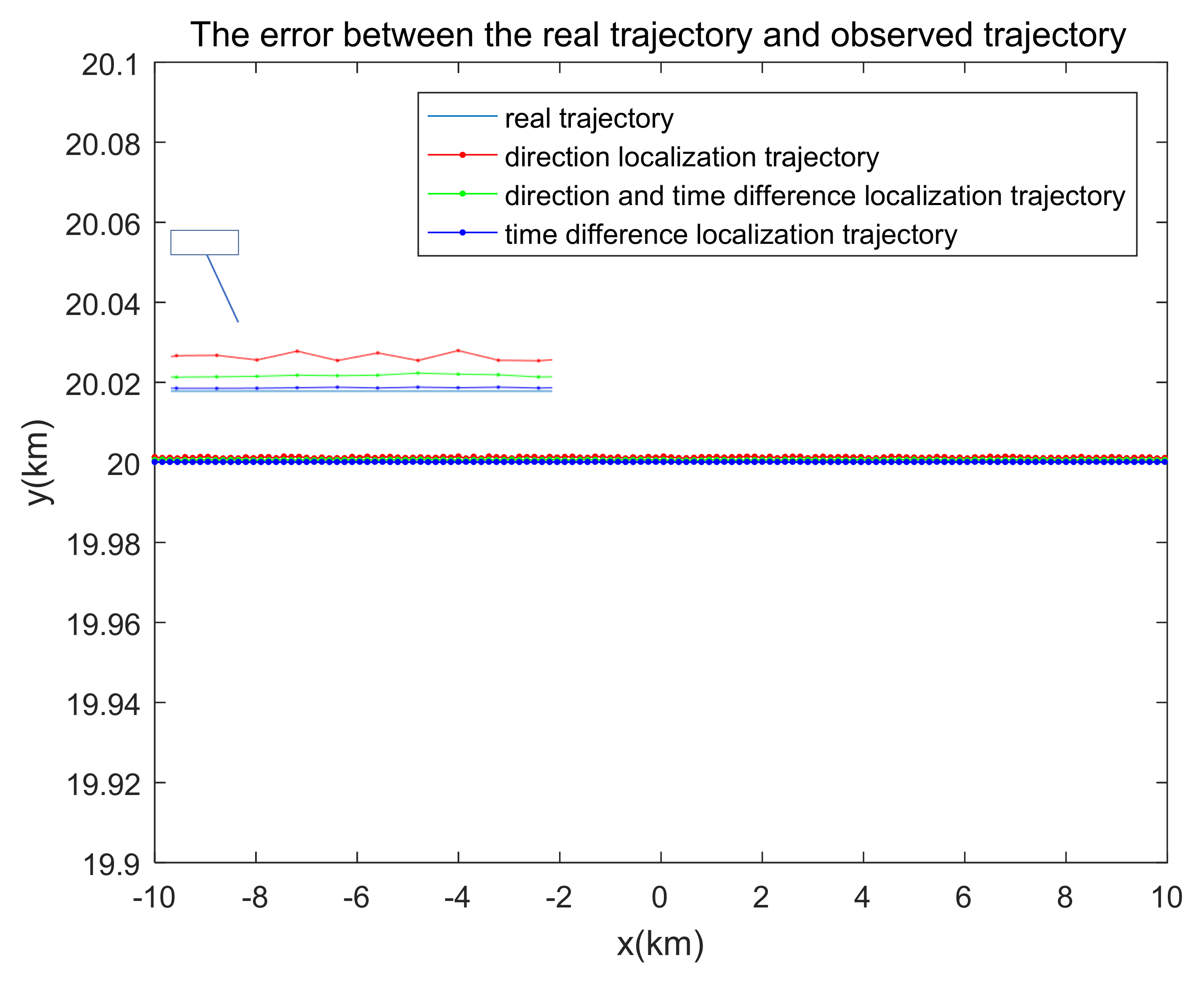
4.2. Experimental Verification of Platforms in Cooperative Localization

According to the above simulation conditions and results of airspace planning, the platforms in the three cooperative localization methods should be arranged in advance to ensure that the detected target flies in a straight line from west to east at the same speed, 50 m/s when the location and simulation conditions are the same; the NUAA-Galaxy UAVs are chosen as the platforms for passive transducers (Figure 11). This paper selects the radio 433 mHz as the passive transducer for localization, as shown in Figure 12. To verify the accuracy of the algorithm, each cooperative localization’s precision is compared, as shown in Figure 13. The platform conducts cooperative detection based on the designated target zone or pre-set action path. The action airspace is solved automatically, and the action path is adjusted correspondingly according to the above airspace design approach. The experiment procedure is shown in Figure 14.
The radio 433 mHz module adopts the sound meter resonator saw to stabilize the frequency, with extremely high frequency stability. When the ambient temperature changes between−25~+85 degrees, the frequency drift is only 3 ppm/degree. The communication mode adopts amplitude modulation AM; the working frequency is between 315 MHz/433 MHz, the frequency stability is ± 75 khz, the emission power rate is ≤500 MW, and the static current is ≤0.1 μA. The emission current is 3~50 mA, and the working voltage is DC 3~12 V. It is especially suitable for multi-transmitter and one receiver wireless remote control and data transmission systems. The frequency stability of the sound meter resonator is second only to crystal, while the frequency stability and consistency of the general LC oscillator are poor. Even if a high-quality fine-tuning capacitor is used, it is difficult to ensure that the adjusted frequency point will not shift due to temperature difference change and vibration. It has many circuit advantages. For example, the transmitting module is not equipped with a coding integrated circuit but adds a data modulation triode Q1. This structure makes it easy to interface with other fixed coding circuits, rolling code circuits and single chip microcomputer, without considering the working voltage and output amplitude signal value of the coding circuit; The data module has a wide working voltage range of 3~12 V. When the voltage changes, the transmitting frequency basically remains unchanged. The receiving module matched with the transmitting module can receive stably without any adjustment; The data module adopts ASK modulation, which can reduce power consumption; The transmitting module is vertically installed on the edge of the main board. If it is more than 5 mm away from the surrounding devices, it can be free from the influence of distribution parameters. The radiation of the module itself is very small, and the shielding effect of mesh grounding copper foil on the back of the circuit module can reduce the leakage of its own oscillation and the intrusion of external interference signals.
Based on the observation results of Platforms A and B or A, B and C, the target’s track is solved, as shown in Figure 13. Each localization platform sends the observation data every 3 s, i.e., the target’s location at the time of observation. The light blue line is the actual track; the red line is the track observed by the localization platform; the green line is the target’s track observed by the direction and time difference localization platform; the dark blue line is the target’s track observed by the time difference localization platform. The errors of the tracks concluded by different cooperative localization approaches are shown in Table 1.
According to the above experimental results, it can be seen that time difference localization is the most precise and stable. Multi-platform cooperation is the most efficient; and the action airspace is vaster. Compared with other cooperative localization approaches, however, there are also some deficiencies, including more platforms, more complex solution of algorithm and more occupied airspace, etc. In actual operation, the optimal cooperative localization strategy should be selected according to the state of operation in the airspace and passive localization transducer’s working state.

4.3. Discussions

(1)
Discussion on simulation results.
In order to verify whether the intersection angle between the target and localization platform can achieve tactical goals, 10 random tracks are formed in the target action zone to calculate the intersection angle between the detection platform and the target (Figure 15, Figure 16 and Figure 17) as well as verify whether tactical goals can be achieved by simulation, as stated in 2.1–2.3. The target’s track is shown in a red solid line in Figure 8, which respectively reveals the tactical requirements on the target and direction localization platform, and the corresponding observation angles, as defined in part 2.
From the above simulation results, the three cooperative localization methods can all meet tactical requirements on localization platform and target track’s observation angle, i.e., ranging from 30° to 150°. Moreover, under actual circumstances, the closer to 90° the observation angle is, the more precise the observation is. Thus, restricted by the observation angle, time difference localization is more precise.
(2)
Discussion on experiment.
According to the experimental process and results, the conclusion of the simulation experiment can be effectively verified. After the airspace is planned for the UAV platform, the target is monitored, and the positioning and tracking data are collected. The comparison shows that time difference localization is the most precise and stable model, in which multi-platform cooperation is the most efficient, and the action airspace is vaster.

5. Conclusions

In this paper, an adaptive dynamic cooperative positioning method is proposed, which can autonomously plan the surveillance airspace according to the actual platform loading situation and target tasks and complete the positioning and tracking of specified targets and areas at the lowest cost. By simulative operation, within the designated target airspace, the optimal action airspace (action route) can be generated automatically based on the platforms’ cooperation mode. By analyzing the experimental data, it can be concluded that TDOA location has the highest accuracy and the smallest error, but requires the most passive sensors to work together, with huge computational power demand and the widest airspace occupied. If there are sufficient resources, sufficient sensors and large enough activity range, TDOA location can be adopted. However, in practical application, considering resource constraints and cost optimization, the hybrid positioning of direction and TDOA can also meet the requirements of high precision and high stability. Only two sensors work together. They have the widest detection range and realize the goal of minimizing the scope of platform airspace planning, which can be used as the optimal scheme. Moreover, with multi-platform real-time location sharing and non-center allocation calculation, it is shown that the actual cooperative localization area is highly overlapped with the target zone. The methods proposed in the paper can serve as the basis of independent adjustment of action route. Under the condition of designated action route, the cooperative localization area can be drawn dynamically. In general, compared with other current research methods, the models and algorithms built up in the paper are simple, reliable, and operable, providing smooth services and convenience for the calculation of system distribution in networks as well as applications.

Author Contributions

Y.Z. and Y.M. contributed to the conception of the study; Z.T. performed the experiment; Y.M. and Z.T. performed the data analyses and wrote the manuscript; Z.C. helped perform the analysis with constructive discussions. All authors have read and agreed to the published version of the manuscript.

Funding

The Ministry of Science and Technology (Grant No.2020YFB2104200) and the National Natural Science Foundation of China (Grant No.42274051).

Data Availability Statement

The data that support the findings of this study are available from the first author, [Yi Mao], upon reasonable request.

Conflicts of Interest

The authors declare that they have no conflict of interest.

References

  1. Chen, C.-K.; Gardner, W.A. Signal-selective time-difference of arrival estimation for passive location of man-made signal sources in highly corruptive environments. I. Theory and method. IEEE Trans. Signal Process. 1992, 49, 1168–1184. [Google Scholar]
  2. Whitcombe, D.W. Pseudo-State Measurements Applied to Recursive Nonlinear Filtering. Available online: https://www.readcube.com/articles/10.21236%2Fad0767189 (accessed on 4 August 2022).
  3. Lindgren, A.G.; Gong, K.F. Position and Velocity Estimation via Bearing Observations. IEEE Trans. Aerosp. Electron. Syst. 1978, AES-14, 564–577. [Google Scholar]
  4. Jean, O.; Weiss, A. Geolocation by direction of arrival using arrays with unknown orientation. IEEE Trans. Signal Process. 2014, 62, 3135–3142. [Google Scholar]
  5. Wang, Y.; Ho, K.C. An asymptotically efficient estimator in closed-form for 3-D AOA localization using a sensor network. IEEE Trans. Wirel. Commun. 2015, 14, 6524–6535. [Google Scholar] [CrossRef]
  6. Liu, Y.; Guo, F.; Yang, L.; Jiang, W. An improved algebraic solution for TDOA localization with sensor position errors. IEEE Trans. Commun. Lett. 2015, 19, 2218–2221. [Google Scholar] [CrossRef]
  7. Foy, W.H. Position-location solution by Taylor-series estimation. IEEE Trans. Aerosp. Electron. Syst. 1976, 12, 187–194. [Google Scholar] [CrossRef]
  8. Yu, H.; Huang, G.; Jun, G.; Wu, X. Approximate maximum likelihood algorithm for moving source localization using TDOA and FDOA measurement. Chin. J. Aeronaut. 2012, 25, 593–597. [Google Scholar] [CrossRef]
  9. Guo, F.C.; Ho, K.C. A Quadratic Constraint Solution Method for TDOA and FDOA Localization. In Proceedings of the 2011 IEEE International Conference of Acoustics, Speech and Signal Processing, Prague, Czech Republic, 22–27 May 2011; Institute of Electrical and Electronics Engineers: Piscataway, NJ, USA, 2011; pp. 2588–2591. [Google Scholar]
  10. Chan, Y.T. Bias Reduction for an Explicit Solution of Source Location Using TDOA. IEEE Trans. Signal Process. 2012, 60, 2101–2114. [Google Scholar]
  11. Matiosevic, M.; Salcic, Z.; Berbe, S. A Comparison of Accuracy Using a GPS and a Low-Cost DGPS. IEEE Trans. Instrum. Meas. 2006, 55, 1677–1683. [Google Scholar] [CrossRef]
  12. Yang, J.; Wu, Q.S. GPS Principles and Its Matlab Simulations. Syst. Eng. Theory Pract. 2011, 1, 114–119. [Google Scholar]
  13. Cong, L.; Zhuang, W. Hybrid TDOA/AOA Mobile User Location for Wideband CDMA Cellular Systems. IEEE Trans. Wirel. Commun. 2002, 3, 439–448. [Google Scholar] [CrossRef]
  14. Yin, J.; Wan, Q.; Yang, S.; Ho, K.C. A simple and accurate TDOA-AOA localization method using two stations. IEEE Signal Process. Lett. 2016, 23, 144–148. [Google Scholar]
  15. Mao, Y.; Yang, Y.; Hu, Y. Research into a Multi-Variate Surveillance Data Fusion Processing Algorithm. Sensors 2019, 19, 4975. [Google Scholar] [CrossRef]
  16. Liu, C.; Yang, J.; Wang, F. Joint TDOA and AOA location algorithm. J. Syst. Eng. Electron. 2013, 24, 183–188. [Google Scholar] [CrossRef]
  17. Fan, H.; Jiang, J.; Sun, X. 3D path planning for two-aircrafts cooperative cross positioning. Transducer Microsyst. Technol. 2020, 39, 26–28. [Google Scholar]
  18. Sun, R.; Wang, G.; Zhang, W.; Hsu, L.-T.; Ochieng, W.Y. 2019, A gradient boosting decision tree based GPS signal reception classification algorithm. Appl. Soft Comput. 2020, 86, 105942. [Google Scholar] [CrossRef]
  19. Yang, Y.; Nan, Y.; Tong, M. Cooperative Route Planning for Multiple Aircraft in a Semifree ATC System. Math. Probl. Eng. 2018, 2018, 3521905. [Google Scholar] [CrossRef]
  20. Waschk, A.; Krüger, J. Automatic route planning for GPS art generation. Comput. Vis. Media 2019, 5, 303–310. [Google Scholar] [CrossRef]
  21. Zhang, Y.; Jiao, L.; Yu, Z.; Lin, Z.; Gan, M. A Tourism Route-Planning Approach Based on Comprehensive Attractiveness. IEEE Access 2020, 8, 39536–39547. [Google Scholar] [CrossRef]
  22. Taha, A.-E.; AbuAli, N. Route Planning Considerations for Autonomous Vehicles. IEEE Commun. Mag. 2018, 56, 78–84. [Google Scholar] [CrossRef]
  23. Li, W.; Xu, C.; He, Y.; Chen, L.; Sun, L.; Fang, G. Design of horizontal airspace dividing radar antenna array. Clust. Comput. 2019, 22 (Suppl. 3), 6767–6780. [Google Scholar] [CrossRef]
  24. Sulistyaningsih, S.; Saputera, Y.P.; Wahab, M.; Maulana, Y.Y. Design of radar display of Indonesian airspace monitoring application. Telkomnika 2019, 17, 1176–1184. [Google Scholar] [CrossRef]
  25. Sun, R.; Zhang, W.; Zheng, J.; Ochieng, W.Y. GNSS/INS Integration with Integrity Monitoring for UAV No-fly Zone Management. Remote Sens. 2020, 12, 524. [Google Scholar] [CrossRef]
  26. Fern, L.; Shively, J. Designing Airspace Displays to Support Rapid Immersion for UAS Handoffs. Proc. Hum. Factors Ergon. Soc. Annu. Meet. 2011, 55, 81–85. [Google Scholar] [CrossRef]
  27. Park, K.H.; Wang, T.; Alouini, M.S. On the Jamming power allocation for secure amplify-and-forward relaying via cooperation jamming. IEEE J. Sel. Zones Commun. 2013, 31, 1741–1750. [Google Scholar] [CrossRef]
  28. Zhai, X.F.; Zhang, Y. IIGA based algorithm for cooperative jamming resource allocation. In Proceedings of the Asia Pacific Conference on Postgraduate Research in Microelectronics, Shanghai, China, 19–21 January 2009; pp. 368–371. [Google Scholar]
  29. Deligiannis, A.; Rossetti, G.; Panoui, A.; Lambotharan, S.; Chambers, J.A. Power allocation game between a radar network and multiple jammers. In Proceedings of the Radar Conference, Philadelphia, PA, USA, 2–6 May 2016; pp. 1–5. [Google Scholar]
  30. Mao, Y.; Sun, R.; Wang, J.; Cheng, Q.; Kiong, L.C.; Ochieng, W.Y. New time-differenced carrier phase approach to GNSS/INS integration. GPS Solut. 2022, 26, 122. [Google Scholar] [CrossRef]
Figure 1. Flowchart of the proposed algorithm.
Electronics 11 02950 g001
Figure 2. Range of direction localization.
Electronics 11 02950 g002
Figure 3. Relationship between intersection angle of two groups of hyperbolic curves and base line AC: (a) Line layout by A, B, C; (b) Triangular layout by A, B, C.
Electronics 11 02950 g003
Figure 4. Design of range of time difference localization. (a) Equilateral triangle layout by A, B, C; (b) Line layout by A, B, C.
Electronics 11 02950 g004
Figure 5. Range of direction and time difference location.
Electronics 11 02950 g005
Figure 6. Optimal airspace distribution in direction localization. Airport.
Electronics 11 02950 g006
Figure 7. Optimal airspace distribution in time difference localization (Airspaces 4 and 6).
Electronics 11 02950 g007
Figure 8. Optimal airspace distribution in time difference localization (Airspaces 4 and 5).
Electronics 11 02950 g008
Figure 9. Target action zone and no fly zone.
Electronics 11 02950 g009
Figure 10. Optimal platform layout: (a) direction localization, (b) direction and time difference localization, (c) time difference localization.
Electronics 11 02950 g010
Figure 11. UAV flatform for passive transducers.
Electronics 11 02950 g011
Figure 12. The 433 mHz radio.
Electronics 11 02950 g012
Figure 13. Observation errors in each cooperative localization approach.
Electronics 11 02950 g013
Figure 14. Experimental flow chart of cooperative localization.
Electronics 11 02950 g014
Figure 15. Intersection angle γ between direction localization platform and each point of the target track.
Electronics 11 02950 g015
Figure 16. Intersection angle γ between direction and time difference localization platform and each point of the target track.
Electronics 11 02950 g016
Figure 17. Intersection angle 2γ between time difference localization platform and each point of the target track.
Electronics 11 02950 g017
Table 1. Observation errors in each cooperative localization approach.
Localization ApproachAverage Error (m)Mean Square Error
Direction localization1.0142.0130 × 10−8
Direction and time difference localization0.4683.1554 × 10−8
Time difference localization0.2072.0476 × 10−10
Publisher’s Note: MDPI stays neutral with regard to jurisdictional claims in published maps and institutional affiliations.

