1. Introduction
Reflector antennas have become quite popular in various projects, and with a practical role in tools for deep-space exploration, the advantage of spaceborne parabolic antennas is growing. Requirements such as larger receiving apertures and wider operating frequency bands have been a trend for a long time, either for large-aperture antennas detecting radio signals in the universe or small-aperture antennas transmitting data [
1,
2]. During deep-space exploration, the detection errors come from signal quality and the degradation of antenna performance. According to the structure of the antenna, the errors caused by the antenna itself can be divided into reflector surface errors and feed errors; both of these degrade the antenna performance [
3] via mechanisms such as surface deformation due to thermal effects and feed displacement due to jitter. Due to the limitations of satellites, spaceborne antennas cannot be calibrated in time, unlike ground antennas. Antennas have become subject to more and more interference factors [
4], but the requirements are getting higher and higher [
5]. Although researchers are trying to apply various methods, there are still many problems that need to be solved [
6]. Thus, studies on the effects of different parameters and errors have a high guiding significance for the design and operation of spaceborne antennas.
For reflector antennas, the studies on the surface errors have been accompanied by studies on the feed errors, and both have been studied for decades. The influence of the feed errors on the radiation characteristics of the antenna has been analyzed [
7]. Some researchers have adopted algorithms to optimize the aperture phase, such as in [
8]. There are also studies that combine the surface errors with the feed and adjust the feed position to compensate for the decline in performance caused by the deformation of the reflector [
9]. The current mainstream research methods are mostly based on physical optics (PO) or geometrical optics (GO) to calculate and analyze the radiation characteristics of the antenna [
10]. For more precise studies, other methods can be adopted for supplementation, such as physical theory of diffraction (PTD) or geometric theory of diffraction (GTD). However, these studies and calculations are not adequate for engineering.
The influences of antenna design parameters on antenna performance are researched in another field. The influences of edge taper illumination on the radiation performance of antennas were studied in [
11]. The degradation effects caused by feed blockage were analyzed by the antenna model in [
12]. The losses of peak gain of an antenna caused by additional losses, such as spillover loss (SPL) phase error loss (PEL) and amplitude taper loss (ATL), were simulated and analyzed in [
13]. However, the influences of practical errors due to surface deformation and feed displacement were not taken into account in these studies.
The maximum peak gain for a reflector can be realized only when there is no surface deformation, no feed error, no ATL, etc. Therefore, the influences of design parameters and errors should be considered more comprehensively from the beginning of the design stage. The attenuation of antenna performance under different reflector subtended angles and different feed displacements was studied based on the reflector antenna model designed in this paper.
The previous research can be divided into two categories. In one, the influence of the feed position error is not considered in the design, and the subsequent observations are analyzed under ideal conditions; the other aims to analyze the feed position error of the antenna in actual operation, and then analyze the change in radiation characteristics. In addition, according to the requirements of different projects on the antenna performance, the influence of the feed displacement is added in advance, which can reduce a lot of subsequent work, such as reducing the hardware calibration cost of the actual project. The research in this paper mainly qualitatively analyzes the influence of feed displacement on the performance of space very long baseline interferometry (SVLBI), as shown in
Figure 1.
This paper is organized as follows.
Section 2 provides the necessary analysis of the question. The simulations and results are given in
Section 3. Conclusions are finally given in
Section 4.
2. Question Analysis
The analysis was divided into two parts. The first part was the conventional analysis method for the feed displacement without considering the actual parameters, and the second part was the analysis of the influence of actual parameters on the antenna performance when there was no feed displacement. However, it should be noted that this paper aimed to analyze the influence of engineering parameters under the premise of feed displacement, rather than to study and analyze the feed error and actual engineering parameters side-by-side, which would be higher-level research.
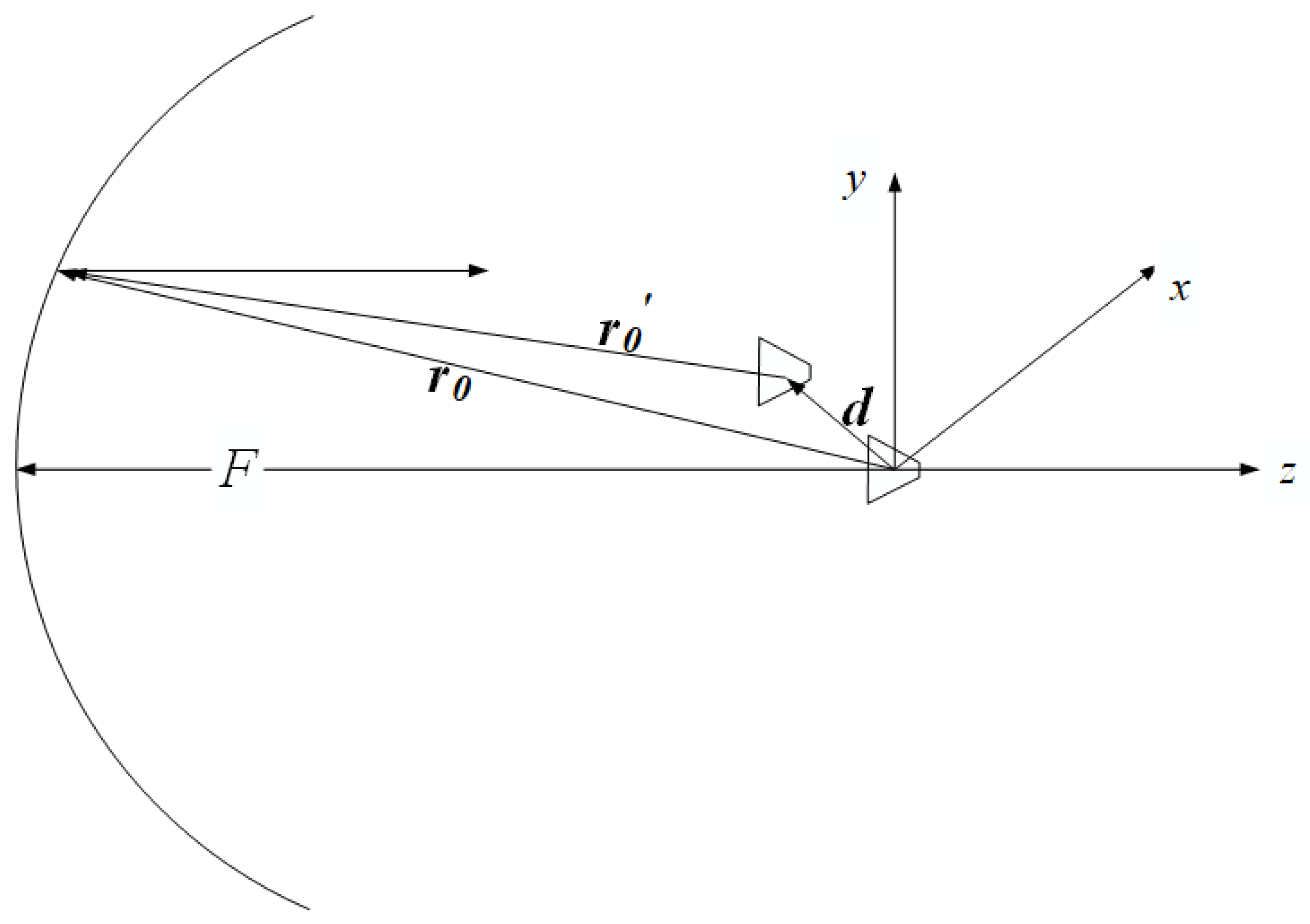
The feed displacement of the reflector antenna can be illustrated as in
Figure 2, where the optical path difference due to feed displacement further distorts the radiation character. The far-field pattern of the reflector antenna is proportional to the Fourier transform of its aperture distribution and can be expressed as Equation (
1). Referring to the analysis method for reflector surface distortion, the phase error caused by the optical path difference can be added to the integral formula, as in Equation (
2) [
14], where the phase error can be calculated by Equation (
3).
Other design parameters related to feed are rarely considered, which can be seen from the above calculations. The mentioned factors’ ATL, as calculated by Equation (
4), PEL, as calculated by Equation (
7), and SPL, as calculated by Equation (
8), affect the actual performance of the antenna in different ways.
where
is the aperture field,
is the half subtended angle of the reflector, and
b is the central blockage radius. The antenna gain should be the same for antennas with the same aperture from Equation (
9), but not in practice. The reason for this is that the factors which decide the actual antenna gain are not only the mentioned ATL, PEL, etc., but also the size of the focal length,
F, type of feed, etc. Furthermore, for the offset parabolic antenna, the offset distance will exert some influence because the offset distance can affect the radiation from the feed to the reflector, such as reducing or avoiding blockage, changing the SPL, sharpening efficiency, etc.
Based on the above analysis, combined with engineering experience, it can be expected that, when there is no feed position error, the antenna gain will first increase and then decrease with the ratio . However, when feed is displaced, the gain loss corresponding to different will be different and difficult to be predict accurately.
The purpose of this paper was to study the effects of focal length on the antenna performance under feed displacement from a more comprehensive perspective for more effective assistance in the design of the antenna. As mentioned above, both the working bandwidth and the aperture are required to increase; however, this paper mainly studied the antenna performance qualitatively under the given conditions. To simplify the experiment, the model of a front-fed parabolic antenna with a single operating frequency is a good choice. The working frequency f = 10 GHz, the aperture of the reflector D = 20 , and the feed type is a pyramidal horn antenna.
3. Simulations and Results
First, it was necessary to find the
corresponding to the maximum peak gain, and the maximum peak gain was used for subsequent comparison and analysis.
Figure 3 gives the experimental results of the maximum peak gain corresponding to
= 0.3:0.1:2.0. It can be seen from
Figure 3 that the value of
corresponding to the current maximum peak gain was around 0.7, and the value of every peak gain in
Figure 3 was normalized by the peak gain when
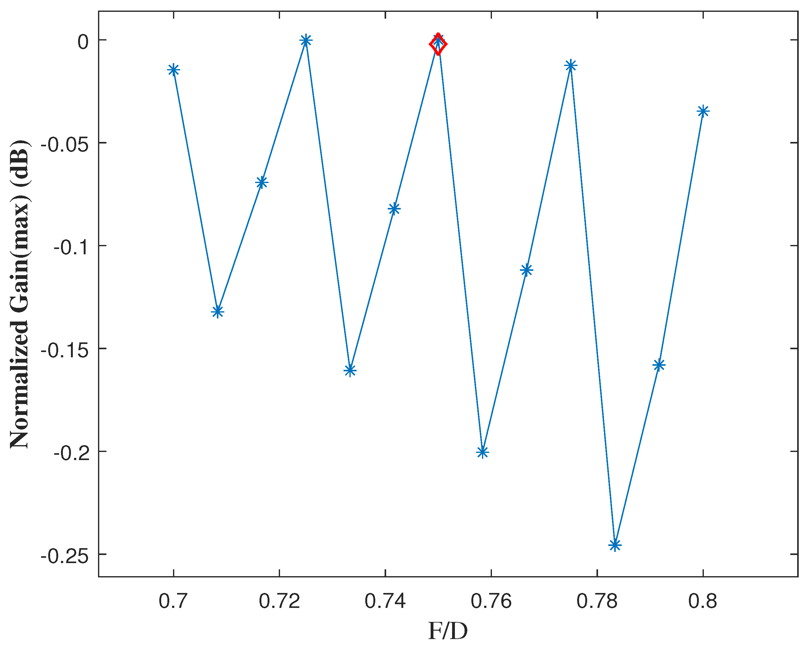
= 0.7. By taking the maximum peak gain as the goal objective, and taking the value of
as the optimization variable, the solution is shown in
Figure 4. The value of
corresponding to the maximum peak gain was 0.75, and the value of every peak gain in
Figure 4 was normalized by the peak gain when
= 0.75.
From
Figure 3 and
Figure 4, it can be seen that the peak gain corresponding to each
differed from each other significantly, even though there was no feed displacement. In addition, the maximum difference was close to 6 dB, which verifies that the actual gain does not depend on the reflector aperture alone. Whether it is ATL, SPL or feed blockage, it can decrease the antenna gain and increase the side-lobe level. Therefore, the following experiments were carried out in HFSS to study the influence of feed displacement more practically.
The feed displacement can be decomposed into axial and lateral. Compared with the lateral position deviation of the feed, the influence of the axial displacement on the antenna performance was much smaller, which can be verified by
Figure 5.
Figure 5 shows the far-field patterns for
d = 0, 0.5
(axial) and 0.5
(lateral) when
= 0.75. The first two almost completely coincided and differed from the last one. Thus, research should focus on the lateral displacement of the feed according to the above results and analysis.
Figure 6,
Figure 7 and
Figure 8 show the peak gain of each
with feed lateral displacement
d = 0.1
, 0.5
and
, which are normalized with the peak gain of the antenna without feed displacement when
= 0.75. The gain degradation shown in
Figure 6 was relatively small when the lateral displacement of the feed was 0.1
. For all focal lengths
F,
, which determines the results and is a relatively ideal situation in practical engineering, was quite small. In addition, when
1, the degradation of the antenna peak gain was higher than that when
> 1, and the major factor was the size of
F.
It can be seen from
Figure 7 that when the lateral displacement of the feed was 0.5
, the largest peak gain corresponded to
= 1. However, like the peak gains of other
, there was a significant degradation, where the maximum drop reached 5.21 dB (
= 0.4). The feed displacement could not be ignored anymore in this case, and the additional loss was no longer the dominant factor compared to the effects of feed displacement.
It can be seen from
Figure 8 that when the lateral displacement of the feed was
, the maximum gain appeared at
= 2.0, the drops of the antenna peak gains at other
were more than 10 dB, and the maximum drop reached 28.68 dB (
= 0.5). As seen in
Figure 8, only the gain declined seriously for
= 2.0, but the loss had already exceeded 20 dB for
= 0.75. However, it should be noted that the practical value was lost for all
due to the severe performance. Combining the above three experimental results, it can be said that the performance of the optimal
in the design of the antenna cannot remain relatively optimal under different lateral feed displacement conditions. Therefore, the parameters of the antenna should be determined according to the specific application scenarios and needs, combined with the actual interference degree.
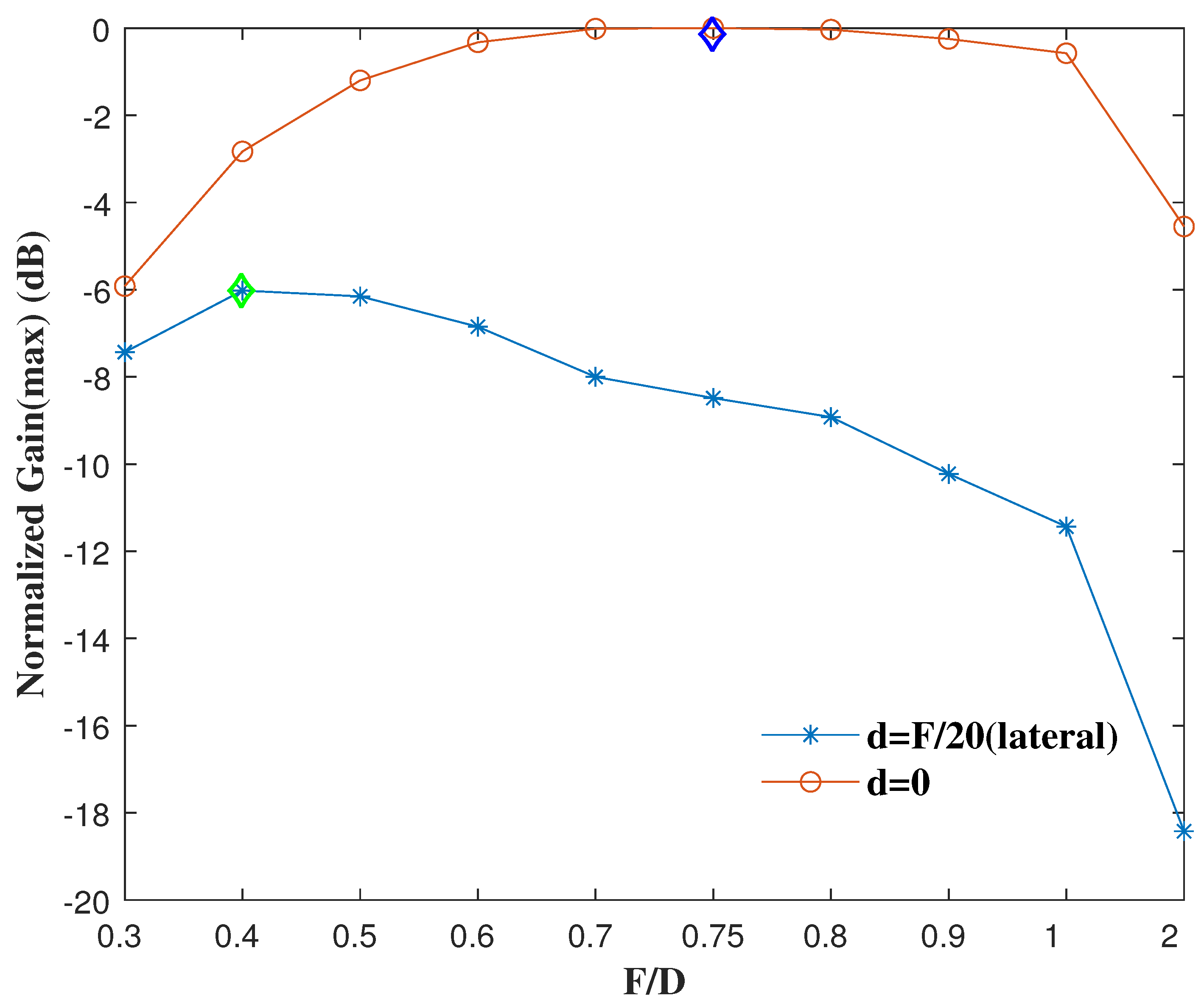
The effects of displacement are not similar for different values of
F. In practical antenna design, some redundancy is usually considered.
Figure 9 shows the peak gains when the feed displacement was
F/20 for all
. The maximum peak gain in this case corresponded to
= 0.4. In addition, gain loss decreased as focal length decreased; however, except for
= 0.3 and 0.4, all the peak gains exceeded more than 5 dB.
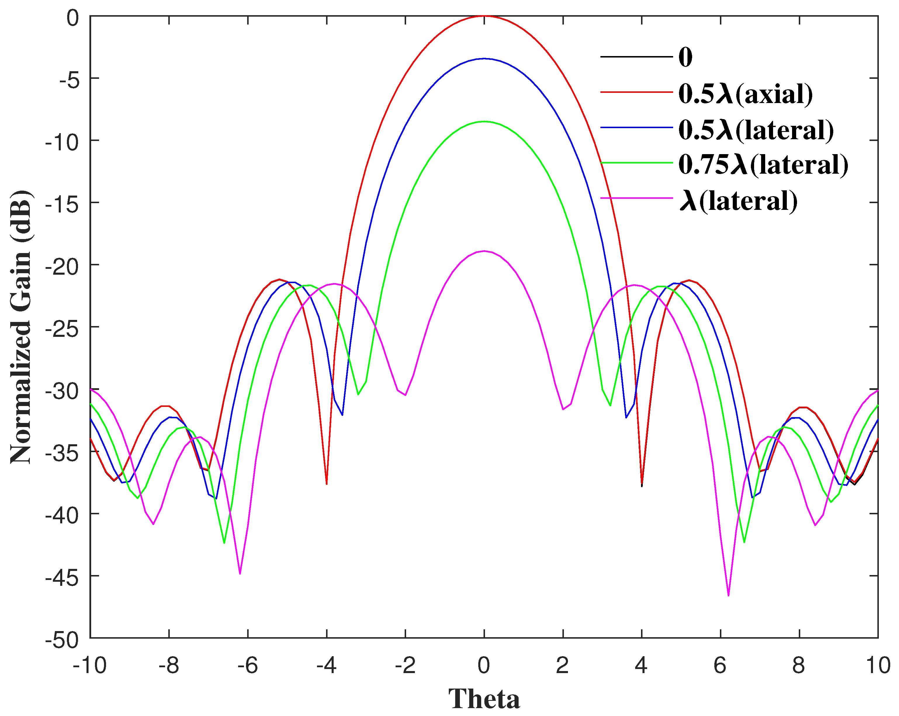
When
= 0.75, the far-field patterns of feed lateral displacement at 0, 0.5
(axial), 0.5
(lateral), 0.75
(lateral) and
(lateral) are shown in
Figure 10. This simulation was carried out to analyze the effect of feed displacement at the initial optimum
= 0.75. The gain changes were expected and consistent with the results above. Axial displacement had little effect, and gain loss increased rapidly as lateral displacement increased. Although the antenna gain decreased, the beam width decreased when the lateral displacement increased. For the engineering background of this paper, the gain is the main consideration, but when the beam width is the main limitation, this situation is worth referring to and digging into deeply. Furthermore, the differences in the first side-lobe level were relatively small, which may shed light on some specific research.


