Article

Research on Optimization of Horizontal Omnidirectional Misalignment Tolerance of WPT Based on Double D Coupler

1
State Grid Electric Power Research Institute, NARI Group Corporation, Nanjing 211106, China
2
State Grid Jiangsu Electric Power Company, Huai’an Power Supply Company, Huai’an 223022, China
3
State Grid Shanghai Electric Power Company, Shanghai 200122, China
4
Department of Electrical and Automation Engineering, Nanjing Normal University, Nanjing 210046, China
*
Author to whom correspondence should be addressed.
Electronics 2022, 11(14), 2163; https://doi.org/10.3390/electronics11142163
Submission received: 11 June 2022 / Revised: 5 July 2022 / Accepted: 6 July 2022 / Published: 11 July 2022

Abstract

:
DD (Double D) coils have been researched and utilized due to their excellent misalignment tolerance. Here, a compound DD coupler sets for stationary wireless power chargers, which has significantly better anti-misalignment performance than single DD coupler in all directions, is proposed. The transmitting coils are composed of two parts of DD coils wound in opposite directions. Moreover, to obtain the low-level variation of mutual inductance between compound transmitting coils and receiving coils when offset occurs, a parameter optimization strategy of compensation coils is also proposed. With the properly designed parameters, the mutual inductance between transmitting and receiving coils could remain basically constant when misalignment occurs, which means that the efficiency and power remain relatively constant when offset occurs. Finally, both single DD coils and compound DD coils experimental prototypes are built to compare anti-misalignment ability performance. The results show that the proposed system is basically more stable and has a higher output power and more stable efficiency than that of unoptimized coupler during migration. In particular, with the employment of the antiparallel winding, the efficiency fluctuates from 85.5% to 85% when the 0.1-m offset in the X-axis and Y-axis occurs simultaneously. Moreover, the higher and basically more stable output power is also achieved.

1. Introduction

Wireless power transfer (WPT) has become a popular and promising technology in transportation and medical industry [1,2,3,4,5,6]. The WPT technology has gained a lot of attention due to its advantages, with the characteristics of convenience, clean and slight radiation. It is beneficial to WPT systems since the parking locations are usually inaccurate and the misalignment tolerance is crucial. When the misalignment occurs [7], the mutual inductance between transmitting coils and receiving coils may substantially change, resulting in the fluctuation of output power and the efficiency [8,9,10,11]. Nevertheless, the anti-misalignment ability can be improved by shaping the magnetic couplers. For instance, Budhia et al. first proposed a new polarized coil structure named as a double D (DD), which can provide a charge zone five times larger than square coils [12]. The load characteristics of DD coils and higher power density are explored in [13]. Also, the effects of the misalignment with rectangular coils are analyzed in [14]. Yang et al. proposed a H-shaped magnetic core to achieve 95% efficiency when the Y-axis offset is 0.3 m [15]. Yao et al. found that when the magnetic coupler of split flat solenoid coupler (SFSC) was shifted within a 0.4-m misalignment in the X-axis, the current fluctuation was less than 0.09 A [16]. This paper analyzes the offset characteristics of the circular DD coils [17,18]. Compared by rectangular DD coils [19], and due to the high symmetry of circular coils, the influence of long and short sides of rectangular coils on all offset direction can be ignored [20]. This can simplify the analysis on strong misalignment tolerance of DD couplers. Meanwhile, so long as the reverse compensation coils are applied, the efficiency will be reduced as [21] described. However, the anti-misalignment ability can be improved by adding antiparallel winding wound in opposite directions to the original circular DD coils, which can ensure the transmission efficiency and out power reliability in this process that occurs from misalignment to alignment.
This paper proposes the novel structure with high misalignment tolerance and parameter configuration strategy of compensation coils based on DD couplers. Specifically, the offset characteristic of circular DD coils and rectangular DD coils are analyzed and compared in this paper. Taking the consumption of coils, manufacture convenience and analysis difficulty into consideration, circular DD coils are selected as the DD coupler. It is widely known that the DD coils share different horizontal anti-misalignment characteristics in X-axis and Y-axis. Hence, this paper presents a compound DD coupler sets for stationary wireless power chargers, which has significantly better anti-misalignment performance than single DD coupler in all directions. Meanwhile, the optimization method of the compound DD coupler is also proposed, which can be applied in wireless charging scenarios with or without magnetic cores. Both the simulation and experiment have proved the feasibility of compensation coils in improving misalignment tolerance of the DD coupler.

2. Theoretical Analysis of WPT

The WPT system is mainly composed of high-frequency AC power supply, compensation capacitor, transmitting coils, receiving coils and equivalent resistance. Figure 1 illustrates the Series-series (SS) resonant compensation topology is adopted in this paper.
Where US is the high-frequency input voltage source, Rtx and Rrx are the total resistances of the transmitting coils and receiving coils, respectively. RL is the resistive load. M is the mutual inductance. Normally, the output power Pout of the system can be represented by
P out = ( ω M | U s | ) 2 R L [ R tx ( R rx + R L ) + ω 2 M 2 ] 2
where ω is the operating angular frequency. The system transmission efficiency can also be derived as:
η = ω 2 M 2 R L [ R tx ( R rx + R L ) + ω 2 M 2 ] ( R 2 + R L )
According to Equations (1) and (2), the output power and efficiency are related to frequency f, M, Rtx, Rrx and RL. Normally, if the load resistance and frequency remain fixed, the output power and efficiency are related to the coil equivalent internal resistance and M. Generally, the mutual inductance will change when the misalignment occurs, resulting in the fluctuation of efficiency and output power. Therefore, it is effective to stable the mutual inductance, which can suppress the variation of efficiency and output power.

3. Optimization of Circular DD Coupler WPT System

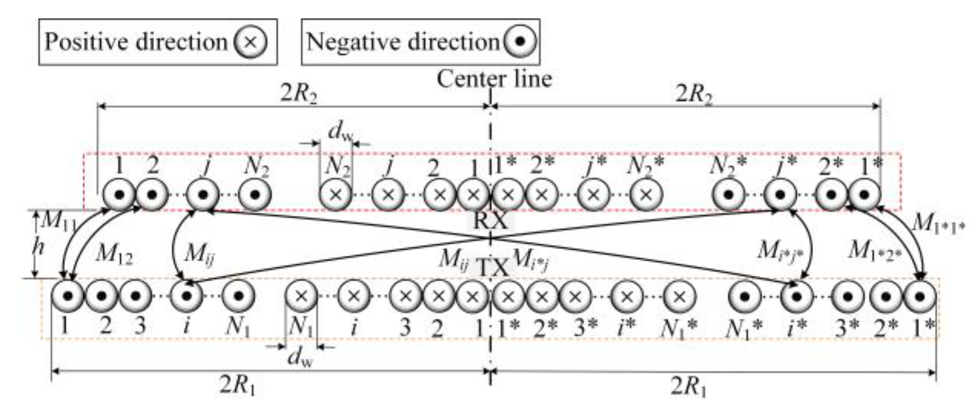
3.1. Mutual Inductance Calculation of Non-Coaxial Circular Coils

The mutual inductance between non coaxial circular coils is given by [22].
M = μ 0 4 π 0 2 π 0 2 π r 1 r 2 cos ( θ φ ) ( r 1 cos θ r 2 cos φ ) 2 + ( r 1 sin θ r 2 sin φ t ) 2 + h 2 d θ  
where, r1 and r2 represent the radius of single transmitting coil and receiving coil, θ and φ are angle integral parameters. The horizontal distance of the center of non-coaxial circular coil is denoted as t, h is the separated gap, μ0 is the vacuum permeability. The multi-turn wound spiral coil can be regarded as a series of coaxial circular coils. Thus, the mutual inductance between two multi-turn spiral coils can be considered as the superposition of mutual inductance between several circular coils. Figure 2 illustrates the half cross section of circular DD coils for intuitive presentation.
In Figure 2, R1 and R2 represent the horizontal distance from the outermost coil to the center of the single coils, respectively. N1 and N2 represent the turns of the single circular transmitting and receiving coils respectively. dw represents the litz wire diameter.
Consequently, the mutual inductance Mtr of the coupler is derived as:
M tr = j = 1 N 2 i = 1 N 1 M i j + j * = 1 N 2 * i = 1 N 1 M i j * + j = 1 N 2 i * = 1 N 1 * M i * j + j * = 1 N 2 * i * = 1 N 1 * M i * j *
where, Mij represents the mutual inductance between the ith transmitting coil and the jth receiving coil. Similarly, Mij* represents the mutual inductance between the ith transmitting coil and the j*th receiving coil. Also, Mi*j represents the mutual inductance between the i*th transmitting coil and the jth receiving coil. Mi*j* represents the mutual inductance between the i*th transmitting coil and the j*th receiving coil.

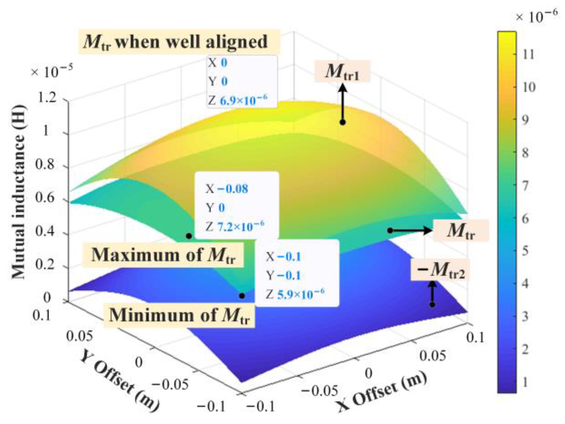
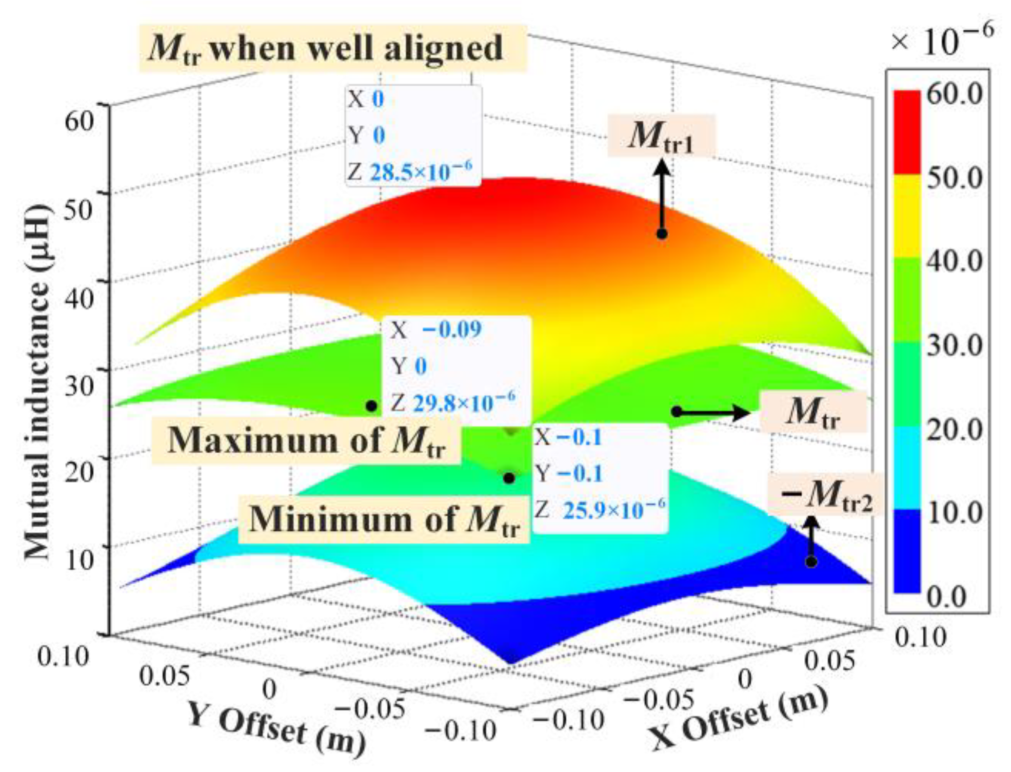
3.2. Analysis of Antimisalignment Characteristics of DD Coupler

To explore the characteristics of DD coupler under different shape of windings, the parameters of circular DD coils and rectangular coils are set as follows, R1 = 0.205 m, R2 = 0.109 m, N1 = 10, N2 = 20, h = 0.15 m, dw = 2.5 mm. Where R1 and R2 represent the radius of the circular transmitting and receiving coils, respectively. h denotes the separation distance between the transmitting coils and receiving coils. Also, the electromagnetic simulation software Ansys Maxwell is employed to obtain the mutual inductance between transmitting and receiving of circular DD and rectangular DD coils, respectively. It should be noted that the rectangular DD coils share the identical circular size with the coils for the fair comparison. The finite element simulation models are shown in the Figure 3. Moreover, the maximum element length of mesh for each model is set as 5 mm.
The anti-misalignment characteristics are illustrated as Figure 4 shown. Mrec and Mtr1 denote mutual inductance between the receiving coils and rectangular coils and circular coils respectively. σrec and σtr1 represent the misalignment tolerance of rectangular coils and circular coils, respectively.
In Figure 4, the misalignment tolerance in the X-axis of DD couplers of both shapes show better performance than that in the Y-axis. In this case, the area and the consumption of rectangular DD coils are slightly larger than that of circular DD coils, which demonstrates greater mutual inductance and better misalignment tolerance in X-axis. However, DD coils in two shapes share the same curve concerning the anti-misalignment characteristic in Y-axis. Nevertheless, different from rectangular DD coils, due to the high symmetry of circular DD coils, the research on long side and short side on the offset characteristics can be exempted. In this paper, the anti-misalignment based on DD couplers will be further explored and optimized. Consequently, the circular DD coils are chosen as the resonator coupler. Furthermore, the finite element simulation results are in good agreement with the numerical simulation results implemented by Matlab based on circular DD coils. To ease the workload of finite element simulation, the analytical simulation is adopted to analyze the coupler without magnetic cores. The structure of the proposed magnetic coupler is shown in Figure 5. The transmitting coils consists of two parts of wires wound in opposite directions, the additional coils are named as compensation coils.
Where Mtr2 is the mutual inductance between the compensation coils and the receiving coils. The values of Mtr1 and Mtr2 can be obtained from Equation (4). N3 represents the turns of the single circular compensation coils. h1 represents the distance between the compensation coils and the transmitting coils. R3 is the radius of a single compensation coils. The above-mentioned parameters are chosen as the optimization factor to improve the anti-misalignment ability of the system. The mutual inductance Mtr between the compound transmitting and receiving coils can be deduced as:
M tr = M tr 1 M tr 2  
When offset occurs, Mtr1 and Mtr2 will decrease simultaneously. Theoretically, the mutual inductance can be stable if the variation amplitude of ΔMtr1 and ΔMtr2 are the same. Therefore, the radius, the number of turns and the gap between primary transmitting coils and compensation coils are taken as the optimized variables to obtain high misalignment tolerance.

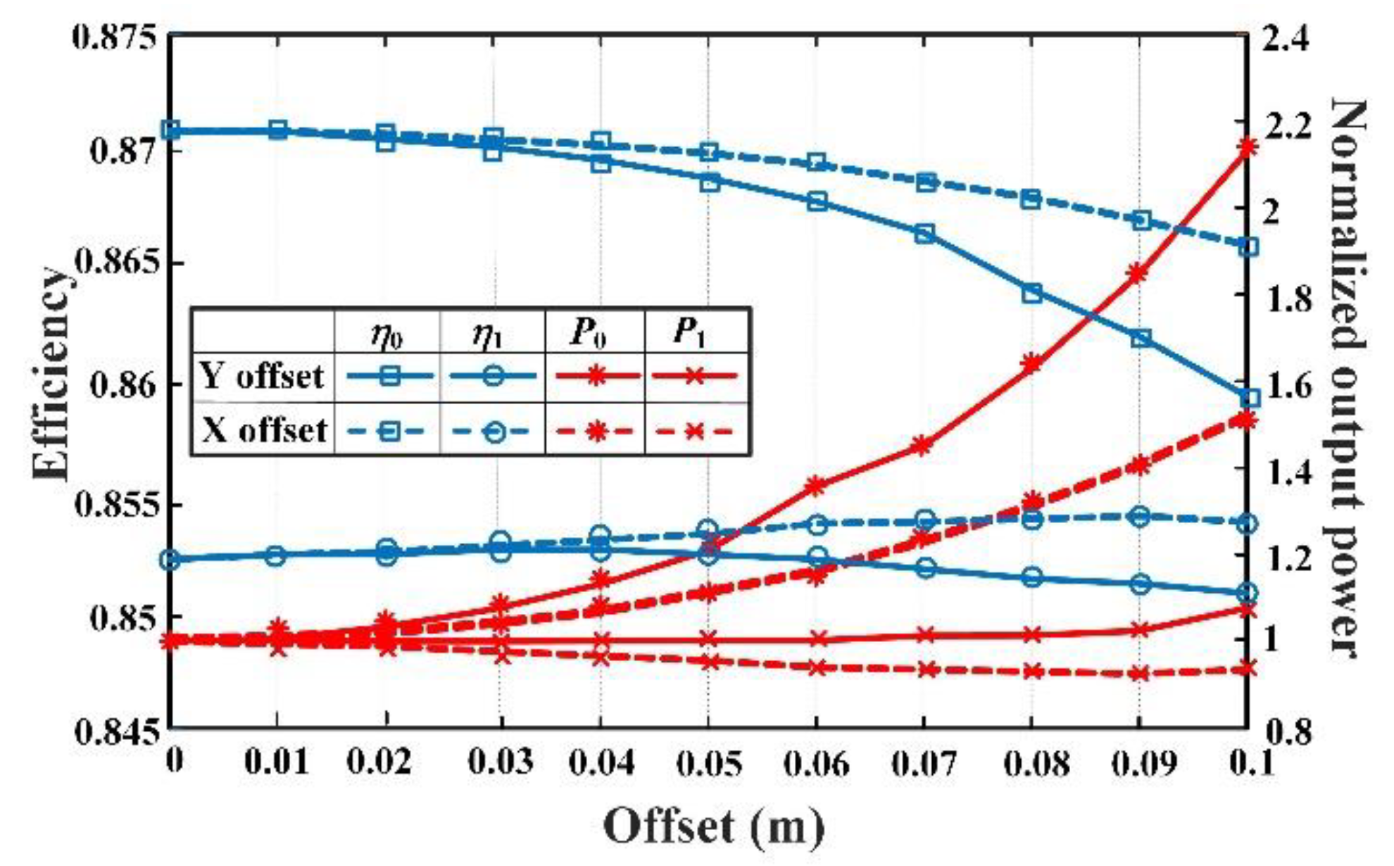
3.3. Analysis on Optimization Strategy for Misalignment Tolerance of Circular DD Coils

To achieve the steady variation of mutual inductance between compound transmitting coils and receiving coils when offset occurs, the joint optimization of multiple parameters of the compensation coil is considered.
The dimension of the compensation coils is smaller than that of the transmitting coils, resulting in a wide range of horizontal spaces for the layout of the compensation coils. Hence, the first step is to optimize R3 for the improvement of the anti-misalignment ability. If the optimized R3 still does not satisfy the desired misalignment tolerance, optimizing h1 and N3 should be considered. Note that the turns of the compensation coils and the gap between the compensation coils and the transmitting coils, limited by internal resistance and longitudinal space, should be appropriate. Then, the priority of the parameters optimization is defined as follows, optimizing R3 > optimizing h1 > optimizing N3. Meanwhile, the separated gap between compensation coils and primary transmitting coils is less than 1/3 of the maximum transmission gap. Denote a as the retention ratio of the original mutual inductance. χ1 and χ2 are denoted as the minimum and maximum misalignment tolerance in the X-axis. Similarly, set χ3 and χ4 as the initial values of the minimum and maximum misalignment tolerance in the Y-axis. The objective function can be written as follows:
{ χ 1 σ i = M i M 0 χ 2 χ 3 σ j = M j M 0 χ 4 a M tr 1 min M tr 1 max M 0 M tr 1 max < 1  
The parameter regulation strategy of the compensation coils is illustrated in Figure 6.
In Figure 6, Mi and Mj denote the mutual inductance of the right endpoint value of the ith interval when offset occurs in the X-axis and the Y-axis, respectively, where i, j = 1, 2, n. M0 is mutual inductance when the system is well aligned. M tr 1 min and M tr 1 max represent the minimum and maximum mutual inductance of the original coupler without compensation coils respectively, when offset happens in the Y-axis direction. σi and σj are the misalignment tolerance in the X-axis and Y-axis respectively. χ1, χ2, χ3, χ4, n, a are the value of the established boundary conditions. Assume that χ1 = χ3 = 95%, χ2 = χ4 = 105%, n = 10, a = 80 mm. Based on the optimization method of compensation coils, shown in Figure 6, the optimized results are calculated as follows: R3 = 86 mm, h1 = 120 mm, and N3 = 6. The Mtr, Mtr1 and Mtr2 versus offset in all directions is illustrated in Figure 7 by numerical simulation.
The color of map based on the variation of Mtr is relatively uniform, which verifies the strong misalignment tolerance of the optimized system. Finally, the simulation results indicate that the misalignment tolerance fluctuates from 85.5% to 104.3% within the maximum offset range of 0.1 m × 0.1 m. When the WPT system is equipped with magnetic cores, the optimization results of parameters on compensation coils are inferred as follows: R3 = 103 mm, h1 =105 mm, and N3 = 7.
When the proposed structure is applied, the misalignment characteristic maps in all directions of Mtr, Mtr1 and Mtr2 by finite element analysis software is simulated, as shown in Figure 8.
In Figure 8, the color of Mtr also shows basically uniform distribution, and the global misalignment tolerance ranges from 91% to 105%. To sum up, the optimization method proposed in this paper for the improvement of anti-misalignment ability can be applied to the case with or without magnetic cores.

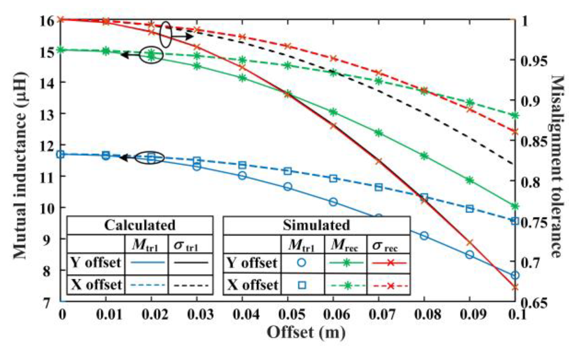
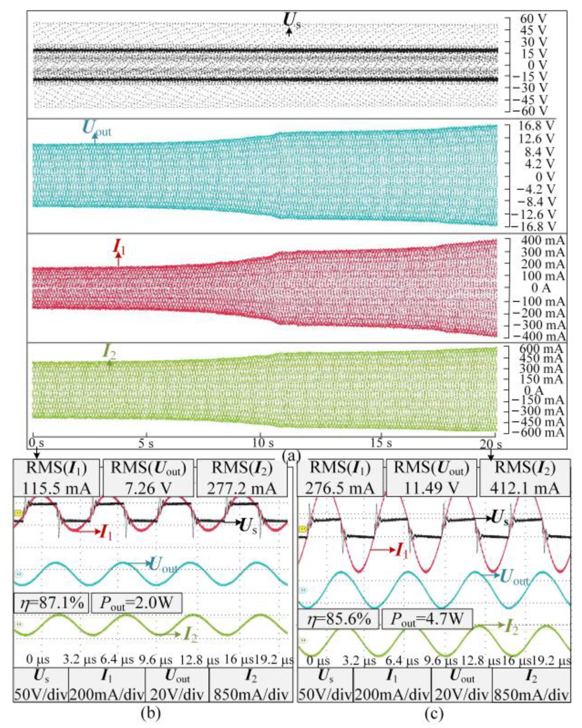
4. Verification Experiment

An experimental prototype shown in Figure 9 is built to verify the proposed design method.
The system consists of an inverter, resonant capacitors, magnetic coupler, laptop for resonant frequency regulation and resistance. The primary transmitting coils and receiving coils are covered by the together piece of 100 × 100 × 10 mm ferrite cuboid NCD LP9.
All of the experimental parameters are listed in Table 1.
Where f denotes the resonant frequency. The waveforms of Us, I1, I2 and output voltage Uout are recorded by the oscilloscope Tektronix MSO54 as Figure 10 and Figure 11 shown. The efficiency can be derived by:
η = | U out | | I 2 | | U s | | I 1 |
The experimental results of the output power and efficiency show that during the offset from (0 m, 0 m) to (0 m, 0.1 m) to (0.1 m, 0.1 m), the efficiency and power of the magnetic coupler equipped with compensation coils change more stable. Meanwhile, the efficiency before compensation decreases by 1.5% and the power increases 2.35 times when maximum offset occurs. On the contrary, the efficiency after compensation decreases by 0.2% and the power increases 1.06 times, which indicates stronger misalignment tolerance regardless of the value of efficiency. Additionally, according to Equations (1) and (2), the output power is related to the Us, while the efficiency is only related to the intrinsic parameters of the magnetic couplers. Hence, the specific efficiency and normalized output power offset characteristic curves versus the X-axis and Y-axis are plotted in Figure 12.
η0 and η1 are the efficiencies without and with compensation coils respectively, P0 and P1 are the output powers without and with compensation coils, respectively. As can be identified from Figure 12, the efficiency fluctuates from 85.5% to 85% when the antiparallel winding is adopted, while that of the primitive system changes significantly from 87.1% to 85.9%. Without compensation coils, the output power fluctuates in multiple-rate at 0.1-m misalignment. By contrast, the proposed system has a higher and basically more stable output power, which greatly reduces the impact of large power fluctuation on power electronic devices.

5. Conclusions

In this paper, compared with rectangular DD coils and considering coil consumption, winding convenience, and analysis difficulty, the circular DD coils are chosen as the resonator coupler. Then, compensation coils wound in the opposite direction are employed to improve the horizontal omnidirectional misalignment tolerance of single circular DD coils. Meanwhile, the parameter regulation strategy of the compensation coils is introduced, which alleviates the fluctuation of efficiency and output power of wireless charging system when offset occurs. Furthermore, the weakness of the single circular DD coils anti-misalignment ability in the Y-axis offset direction is eliminated. Finally, simulations and experiments have been carried out to verify the correctness and feasibility of the system. Results show that the efficiency fluctuates from 85.5% to 85% with the employment of the compensation coils when the 0.1-m offset in the X-axis and Y-axis occurs simultaneously. Furthermore, the higher and more stable output power is also obtained. Hence, the system can be widely used in UAVs (unmanned aerial vehicles) and EVs (electric vehicles).

Author Contributions

Conceptualization, F.C. and P.W.; methodology, P.W and Y.W.; software, C.S.; validation, C.X. and S.W.; formal analysis, W.W.; investigation, Z.D.; resources, F.C.; writing—original draft preparation, C.X.; writing—review and editing, W.W.; supervision, Z.D.; project administration, F.C.; All authors have read and agreed to the published version of the manuscript.

Funding

This research was funded by the Science and Technology Project of SGCC under Grant no. 52094021N00R.

Institutional Review Board Statement

Not applicable.

Informed Consent Statement

Not applicable.

Data Availability Statement

Not applicable.

Conflicts of Interest

The authors declare no conflict of interest.

References

  1. Wang, W.; Zhang, C.; Wang, J.; Tang, X. Multi-purpose flexible positioning device based on electromagnetic balance for EVS wireless charging. IEEE Trans. Ind. Electron. 2021, 68, 10229–10239. [Google Scholar] [CrossRef]
  2. Wang, W.; Xu, C.; Zhang, C.; Yang, J. Optimization of transmitting coils based on uniform magnetic field for unmanned aerial vehicle wireless charging system. IEEE Trans. Magn. 2021, 57, 8600105. [Google Scholar] [CrossRef]
  3. Zhang, Z.; Pang, H.; Georgiadis, A.; Cecati, C. Wireless power transfer—An Overview. IEEE Trans. Ind. Electron. 2019, 66, 1044–1058. [Google Scholar] [CrossRef]
  4. Zhang, C.; Wang, W.; Xu, C.; Yang, J. Research on uniform magnetic field compensation structure of array circular coils for wireless power transfer. IEEE Trans. Magn. 2021, 57, 8600105. [Google Scholar] [CrossRef]
  5. Wang, W.; Yang, J.; Wang, Q.; Cao, W. Comparative design methods of wireless power system for sensors with extended range using Class E inverter at a certain frequency. IET Microw. Antennas Propag. 2020, 14, 908–918. [Google Scholar] [CrossRef]
  6. Shao, Y.; Liu, M.; Ma, C. A multi-receiver MHz WPT system with hybrid coupler. In Proceedings of the 2021 IEEE PELS Workshop on Emerging Technologies: Wireless Power Transfer (WoW), San Diego, CA, USA, 1–4 June 2021; pp. 1–6. [Google Scholar]
  7. Tan, P.; Cao, S.; Gao, X. Adjustable coupler for inductive contactless power transfer system to improve lateral misalignment tolerance. In Proceedings of the 2016 IEEE 8th International Power Electronics and Motion Control Conference (IPEMCECCE Asia), Hefei, China, 22–26 May 2016; pp. 2423–2426. [Google Scholar]
  8. Zhang, Z.; Zhang, B.; Wang, J. Optimal design of quadrature-shaped pickup for omnidirectional wireless power transfer. IEEE Trans. Magn. 2018, 54, 8600305. [Google Scholar] [CrossRef]
  9. Huang, R.; Zhang, B.; Qiu, D.; Zhang, Y. Frequency splitting phenomena of magnetic resonant coupling wireless power transfer. IEEE Trans. Magn. 2014, 50, 8600204. [Google Scholar] [CrossRef]
  10. Zhao, J.; Huang, X.; Wang, W. Wireless power transfer with two-dimensional resonators. IEEE Trans. Magn. 2014, 50, 4002804. [Google Scholar] [CrossRef]
  11. Zhang, Y.; Yan, Z.; Kan, T.; Liu, Y.; Mi, C.C. Modelling and analysis of the distortion of strongly-coupled wireless power transfer systems with SS and LCC–LCC compensations. IET Power Electron. 2019, 12, 1321–1328. [Google Scholar] [CrossRef] [Green Version]
  12. Budhia, M.; Boys, J.T.; Covic, G.A.; Huang, C. Development of a single-sided flux magnetic coupler for electric vehicle IPT charging systems. IEEE Trans. Ind. Electron. 2013, 60, 318–328. [Google Scholar] [CrossRef]
  13. Prosen, N.; Domajnko, J.; Milanovič, M. Wireless Power Transfer Using Double DD Coils. Electronics 2021, 10, 2528. [Google Scholar] [CrossRef]
  14. Prasanth, V.; Bauer, P. Distributed IPT Systems for Dynamic Powering: Misalignment Analysis. IEEE Trans. Ind. Electron. 2014, 61, 6013–6021. [Google Scholar] [CrossRef]
  15. Yang, G.; Dong, S.; Zhu, C.; Lu, R.; Wei, G.; Song, K. Design of a high lateral misalignment tolerance magnetic coupler for wireless power transfer systems. In Proceedings of the 2017 IEEE PELS Workshop on Emerging Technologies: Wireless Power Transfer (WoW), Chongqin, China, 20–22 May 2017; pp. 34–39. [Google Scholar]
  16. Yao, Y.; Gao, S.; Mai, J.; Liu, X.; Zhang, X.; Xu, D. A novel misalignment tolerant magnetic coupler for electric vehicle wireless charging. IEEE J. Emerg. Sel. Top. Ind. Electron. 2022, 3, 219–229. [Google Scholar] [CrossRef]
  17. Bima, M.E.; Bhattacharya, I.; Neste, C.W.V. Experimental evaluation of layered DD coil structure in a wireless power transfer system. IEEE Trans. Electromagn. Compat. 2020, 62, 1477–1484. [Google Scholar] [CrossRef]
  18. Bima, M.E.; Bhattacharya, I.; Hasan, S.R. Comparative analysis of magnetic materials, coil structures and shielding materials for efficient wireless power transfer. In Proceedings of the 2019 IEEE International Symposium on Electromagnetic Compatibility, Signal & Power Integrity (EMC + SIPI), Orleans, LA, USA, 22–26 July 2019; pp. 95–100. [Google Scholar]
  19. Yang, Z.; Chen, Y.; Yang, D.; Du, W.; He, G.; Zhang, X.; Xu, C.; Wang, W. Research on parameter optimization of Double-D coils for electric vehicle wireless charging based on magnetic circuit analysis. IEICE Electron. Expre. 2020, 17, 20200067. [Google Scholar] [CrossRef] [Green Version]
  20. Kurs, A.; Karalis, A.; Moffatt, R.; Joannopoulos, J.D.; Fisher, P.; Solacic, M. Wireless power transfer via strongly coupled magnetic resonances. Sci. Express 2007, 317, 83–86. [Google Scholar] [CrossRef] [PubMed] [Green Version]
  21. Park, J.; Kim, D.; Hwang, K.; Park, H.H.; Kwak, S.I.; Kwon, J.H.; Ahn, S. A resonant reactive shielding for planar wireless power transfer system in smartphone application. IEEE Trans. Electromagn. Compat. 2017, 59, 695–703. [Google Scholar] [CrossRef]
  22. Qian, L.; Chen, M.; Cui, K.; Shi, G.; Wang, J.; Xia, Y. Modeling of mutual inductance between two misalignment planar coils in wireless power transfer. IEEE Microw. Wirel. Compon. Lett. 2020, 30, 814–817. [Google Scholar] [CrossRef]
Figure 1. SS resonant topology.
Electronics 11 02163 g001
Figure 2. Half cross section of circular DD coils.
Electronics 11 02163 g002
Figure 3. The characteristic of DD couplers versus offset: (a) circular DD coils; (b) rectangular DD coils.
Electronics 11 02163 g003
Figure 4. The characteristic of DD couplers versus offset.
Electronics 11 02163 g004
Figure 5. The structure of the proposed compound DD coils.
Electronics 11 02163 g005
Figure 6. Flowchart of parameters optimization of compensation coils.
Electronics 11 02163 g006
Figure 7. Offset characteristic maps in all directions without employing cores.
Electronics 11 02163 g007
Figure 8. Offset characteristic maps in all directions with the employment of cores.
Electronics 11 02163 g008
Figure 9. Experimental prototype of the proposed WPT system.
Electronics 11 02163 g009
Figure 10. Experimental waveforms of Us, I1, I2 and Uout before compensation. Continuous waveform: (a) 0.1-m offset in the Y-axis occurs first and then 0.1-m offset in the X-axis occurs. Stationary waveform: (b) well aligned; (c) 0.1-m offset in the X-axis and Y-axis occurs simultaneously.
Electronics 11 02163 g010
Figure 11. Experimental waveforms of Us, I1, I2 and Uout after compensation. Continuous waveform: (a) 0.1-m offset in the Y-axis occurs first and then 0.1-m offset in the X-axis occurs. Stationary waveform: (b) well-aligned; (c) 0.1-m offset in the X-axis and Y-axis occurs simultaneously.
Electronics 11 02163 g011
Figure 12. Comparison of efficiency and output power.
Electronics 11 02163 g012
Table 1. Parameters of DD couplers.
ParameterValueParameterValue
L1Before compensation 315 μH
After compensation 297 μH
L2329 μH
R1Before compensation 1.6 Ω
After compensation 1.7 Ω
R21.7 Ω
US20 VRL24 Ω
f190 kHz
Publisher’s Note: MDPI stays neutral with regard to jurisdictional claims in published maps and institutional affiliations.

