Article

Study on Co-Estimation of SoC and SoH for Second-Use Lithium-Ion Power Batteries

1
School of Economics and Management, Xi’an University of Technology, Xi’an 710054, China
2
School of Mechanical and Precision Instrument Engineering, Xi’an University of Technology, Xi’an 710048, China
*
Author to whom correspondence should be addressed.
Electronics 2022, 11(11), 1789; https://doi.org/10.3390/electronics11111789
Submission received: 29 April 2022 / Revised: 27 May 2022 / Accepted: 30 May 2022 / Published: 5 June 2022

Abstract

:
Lithium-ion batteries are an ideal power supplier for electric vehicles (EVs) due to their high-power density and wide operating voltage, but their performance decays to 80% before retirement from EVs. Nevertheless, they still have a particular use value after decommissioning, so recycling the retired power battery in cascade can be considered. Therefore, accurate estimation of battery state-of-charge (SoC) and state-of-health (SoH) is crucial for extending the service life and echelon utilization of power lithium-ion battery packs. This paper proposes a comprehensive co-estimation scheme of battery SoC/SoH for the second-use of lithium-ion power batteries in EVs under different cycles using an adaptive extended Kalman filter (AEKF). First, according to the collected battery test data at different aging cycle levels, the external battery characteristics are analyzed, and then a cycle-dependent equivalent circuit model (cECM) is built up. Next, the parameter estimation of this battery model is performed via a recursive least square (RLS) algorithm. Meanwhile, the variations in internal battery parameters of the cycle numbers are fitted and synthesized. Moreover, validation of the estimated parameters is further carried out. Based on this enhanced battery model, the AEKF algorithm is utilized to fulfill battery SoC/SoH estimation simultaneously. The estimated results of SoC/SoH are obtained for a LiCoO2 cell in the case of CCC (constant current condition) under different cycle times. The results show that this proposed co-estimation scheme can predict battery SoC and SoH well, wherein the peak values of the SoC errors are less than 2.2%, and the peak values of SoH, calculated by the estimated capacity and internal resistance, are less than 1.7% and 2.2%, respectively. Hence, this has important guiding significance for realizing the cascade utilization of lithium-ion power batteries.

1. Introduction

With the booming electric vehicle market, lithium-ion batteries (LIBs) are widely used as a power candidate for electric vehicles (EVs) [1,2]. However, when the performance of an EV’s power battery pack drops to 80% of the original implementation of a new one, it is no longer suitable for use in EVs. After the power LIBs are retired, they maintain high safety and use values. When these power batteries are recycled, it causes waste of resources and environmental pollution. Therefore, it is possible to consider cascade recycling of the retired power LIBs. Both state-of-charge (SoC) and state-of-health (SoH) are two important indicators for second-use LIBs. Hence, the accurate estimation of battery SoC/SoH for lithium-ion power batteries is crucial for increasing the operation range of EVs as well as prolonging the service life and second use of the power LIBs [3,4,5].
It is well known that battery SoC is a vital real-time indicator of the residual capacity of a battery cell/system with respect to its rated capacity. It helps to predict the remaining mileage and driving time of EVs. To date, many researchers and scholars have contributed to the SoC estimation algorithm for various types of LIBs; current SoC estimation methods mainly include the coulomb counting approach [6,7], the model-based open circuit voltage (OCV) approach [8,9,10], the neural network model approach [11,12,13], the Kalman filter (KF) family approach [14,15,16], etc. Here, the KF-based approach is an effective method that integrates coulomb-counting technology with model-based OCV prediction. In particular, KF-based SoC estimation has been widely applied in recent decades due to its accuracy and robustness. It is important to note that battery SoH is usually employed to depict the aging performance of LIBs, which is reflected by the capacity loss or the resistance increment [17], and the existing SoH estimation methods are mainly divided into two categories: experimental analysis methods and model-based approaches. Experimental analysis methods include direct measurement methods, the voltage trace method [18] and approaches based on an incremental capacity analysis (ICA) [19] and differential voltage analysis (DVA), etc. Model-based algorithms include the Kalman filter family algorithms [20], particle filter algorithms [21], neural network algorithms [22,23], support vector machines [24,25], genetic algorithms [26], artificial intelligence algorithms [27] and data-driven methods [28,29]. With flourishing use of EVs, the batteries’ capacities and internal resistances often vary with aging cycle times, which reduces the estimation accuracy of battery SoC and SoH, especially when the battery has been charged and discharged after many cycle times. Therefore, to make the estimation of battery SoC and SoH reasonable and effective, it is challenging to consider the cycle times. Battery SoC/SoH estimation methods are summarized in Table 1 and Table 2, respectively.
Recently, a number of research papers have reported on the battery aging cycle, including capacity estimation, resistance estimation, SoH estimation and remaining useful life (RUL) estimation. For example, capacity fade can be modeled by using two exponential functions of discharge cycles and analyzing the battery data in [30]. An empirical model based on the physical degradation phenomena of LIBs was developed, and the RUL was predicted based on data available through battery capacity monitoring. Xing et al. [21] constructed an ensemble model to capture the capacity degradation and predict the battery’s remaining functional performance. Zhang et al. [31] proposed a stochastic framework in terms of the SoC estimation to predict the remaining discharge time based on the Thevenin model, and the experimental results demonstrated that the proposed prediction framework had great effectiveness as it has the capability of accurately predicting the remaining discharge time under different operations and uncertainties. Liang et al. [32] used ohmic resistance as a SoH indicator to evaluate the batteries’ performances by combining the equivalent circuit model (ECM) and data-driven model; the results showed that the proposed method was feasible for the implementation of a battery management system in real-world EVs. Wu et al. [33] proposed a SoH estimation method based on the long short-term memory (LSTM) by using the voltage profile acquired during the charging and discharging process through the cycle life test; a grey relation analysis and the entropy weight method were employed to analyze the healthy features, and the LSTM technique was then established to achieve the SOH estimation of LIBs.
Most of the aforementioned studies on the battery life cycle only focus on one battery state, such as the battery SoC, SoH, RUL, capacity, internal resistance, etc.; however, there are a few studies that focus on two states. These include Li et al. [34], who proposed a co-estimation scheme based on ECM for battery capacity and SoC estimations. The recursive least squares (RLS) method and an adaptive extended Kalman filter (AEKF) were combined to attain an online parameters identification model and SoC estimation. Hu et al. [35] determined the SoC reliance of the nominal parameters of a Thevenin model, and the performance degradation of the nominal model over the battery lifetime was quantified. Then, the SoC was estimated in real-time utilizing a second-order EKF, and the SoH (the capacity and internal ohmic resistance) was updated offline in a fourth-order EKF. Ouyang et al. [36] proposed a co-estimation scheme of the SoC, SoH, and state-of-function (SoF) for LIBs in EVs. The model-based SoC estimation was fulfilled by the EKF. The battery parameters relevant to the battery SoH and SoF were identified online using the RLS method with a forgetting factor; the capacity and the maximum available output power were then estimated based on the identified parameters. Du et al. [37] proposed an adaptive sliding mode observer to estimate the battery SoC and SoH based on 2RC-ECM, avoiding the influence of buffeting and improving the estimation performance. In summary, proposing a comprehensive state prediction scheme that can concurrently estimate the SoC and SoH is significant and challenging. Furthermore, to apply the current battery model to a longer lifespan and provide a higher accuracy SoC and SoH estimation for the model-based estimation method, it is necessary to consider different aging cycle levels based on the standard ECM model.
Table 1. Summary of battery SoC estimation methods.
ApproachMajor BenefitsMajor LimitationsApplication Conditions
Coulombic counting [6,7]Easy implementation; online; low power consumption.Error accumulation; needs accurate initial SoC current.In conjunction with various methods.
OCV method [8,9,10]Easy to understand; initial SoC calibration.Time-consuming; long relaxation time.SoC offline estimation in the lab.
NN [11,12,13]Independent model; great accuracy; high universality.Large amount of training data; generalization ability issues.Needs numerous experimental data.
KF [14,15,16]Online; insensitive to initial SoC; pinpoints accuracy.Relies on model accuracy; domain knowledge required.Accurate battery model.
EKF [35,36]High accuracy; strong robustness.Impractical assumption of white Gaussian noise.Accurate battery model.
Table 2. Summary of battery SoH estimation methods.
ApproachMajor BenefitsMajor LimitationsApplication Conditions
Voltage trace method [18]Easy to understand; simple structure and low cost.Online estimates are difficult to achieve.Fixed environment, such as lab.
ICA [19]High measurement accuracy, easy to implement.Repeated charge-discharge tests are required.SoH estimation in the laboratory.
KF [20]Online; high accuracy.Relies on model accuracy; domain knowledge required.Accurate battery model.
PF [21]High accuracy; strong robustness, handles non-Gaussian system noise well.Dimension of sampling space reduced; a large sample size.Accurate battery model.
Data-driven method [22,23,24,25,26,27,28,29]Excellent learning and generalization abilities; strong nonlinear mapping ability.Large amount of training data; time-consuming trial and error process.High performance processors; data storage technology conditions.
Based on the second-use LIBs, this paper starts with several vital indicators, such as SoC, battery capacity and internal resistance sum, and a series of charge-discharge cycle tests were performed on certain LIBs. First, based on the 2RC-ECM, an improved battery model considering the impact of different cycle times is established. Then, an AEKF algorithm considering the influence of cycle times is utilized to estimate the SoC, capacity and internal resistance of a LIB cell simultaneously. The battery state estimation can be effectively applied to the long-life cycle. The main contributions of this study are summarized as follows: (i) The OCV-SOC cycle table is established to describe the OCV-SOC relationship under different cycles by considering the differences in batteries’ OCV-SOC curves under different cycles; (ii) the relationship between parameters and cycle times is obtained by the RLS method; and (iii) an AEKF is applied to simultaneously estimate battery SOC, capacity and internal resistance, and the SOH[Ccap] and SOH[R0] of the battery are obtained by the definition formula of residual power and the definition formula of internal resistance, respectively. The decay characteristics of the main performance parameters, such as SoC, ohmic internal resistance and battery capacity, are compared and analyzed, which is of guiding importance for the cascade use of decommissioned batteries in energy storage systems to maximize the value of retired batteries.

2. Second Use Framework and Battery Experimental System

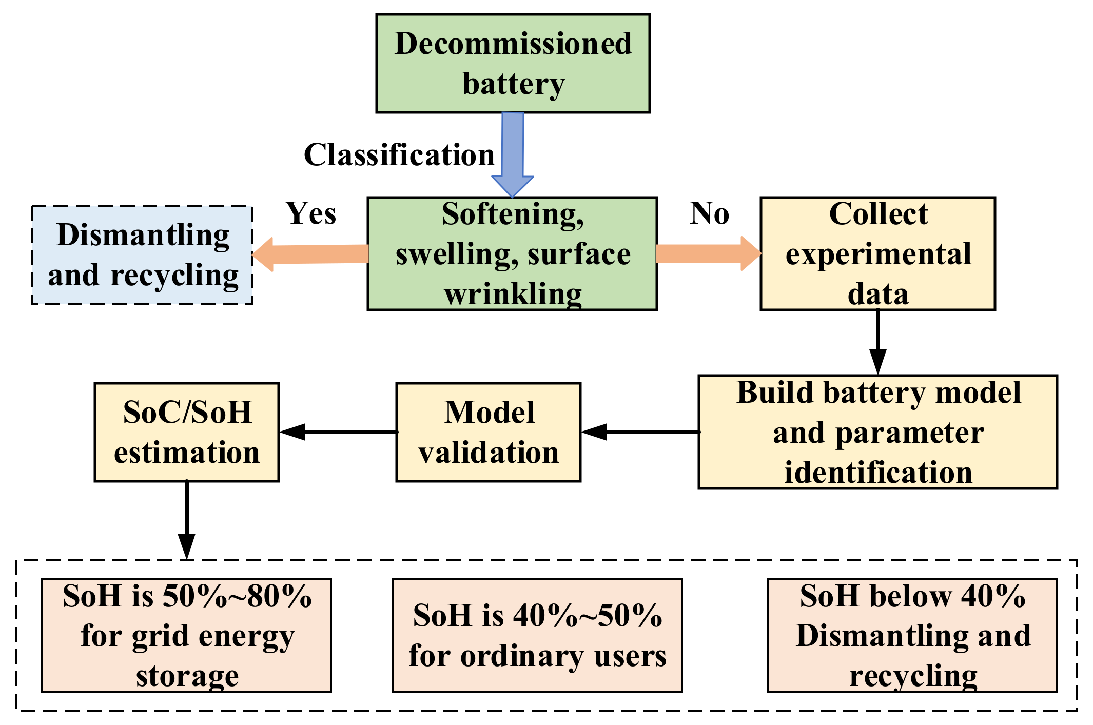
2.1. Second-Use Framework of Vehicle Power Battery

For the retired LIBs in EVs, they may be reused in cascade scenarios when their functional components are practical, which is of great significance for improving their life cycle utilization value, reducing the cost of producing LIBs and alleviating environmental pollution problems. To maximize the value of cascade utilization batteries, it is necessary to research sorting and performance analyses of batteries based on several critical indicators, such as battery SoC, capacity and internal resistance. To correctly estimate the SOC/SOH of a LIB cell, accurate establishment of the battery model is necessary. First, based on the 2RC-ECM, the selected single cells are subjected to constant current discharge experiments in a standard test environment to perform parameter identification and SOC-OCV curve identification, and the model validation is performed. Afterward, a co-estimation of the battery SoC/SoH is proposed and verified. Finally, according to the battery SoC/SoH estimation results, some valuable suggestions are made for the second-use LIBs. It is noted that a battery SoH of 50~80% is used in energy storage devices, such as power grids and new energy power generation. SoH of 40~50% is used in ordinary users. When the SoH is less than 40%, the battery is disassembled and recycled. The specific power battery cascade utilization framework process is shown in Figure 1.

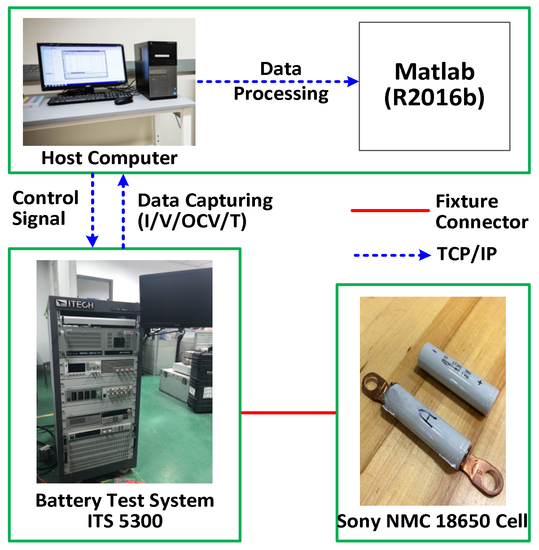
2.2. Battery Experimental System

The battery experimental setup revealed in Figure 2 is used to collect the test profiles, which contain (1) a battery test system (ITS 5300, ITECH Inc., South Burlington, VT, USA); (2) a thermal chamber for controlling the ambient temperature; (3) a host computer; and (4) MATLAB 2016b® for data analysis. Three separate test schedules are undertaken in this empirical setup, which encompasses the constant current condition tests (CCC), static capacity tests, and OCV-SOC tests in the case of driving cycles [30, 100, 200, 300, 600, 800, 1000], separately. The test profiles of CCC, static capacity tests and OCV-SOC tests under different driving cycles are presented in Figure 3a–c, respectively. Moreover, the key specifications of the employed LiCoO2 cell are listed in Table 3.
It is noted that the test profiles at driving cycles [1, 100, 200, 600, 800] are used to identify the parameters of R0, R1, C1, R2 and C2 for a LiCoO2 cell, while the test profiles at driving cycles [30, 300, 1000] are employed to validate the identified parameters of this battery cell; all the test profiles are collected under CCC due to our test setup limitation. The experiments are conducted at 25 °C. The LiCoO2 cell was tested with standard constant current and constant voltage test scheme. First, the cell was charged at a constant current rate of 0.5 C until the voltage reached the upper cut-off voltage of 4.2 V. Then, it was charged at 4.2 V constant voltage until the charging current dropped below 0.05 A. Next, it was left off for 10 min. Finally, it was then discharged at a constant rate of 0.5 C to a cut-off voltage of 2.7 V. In this way, the cell was then recharged and discharged 1000 times, and the constant current discharge curves in different cycle processes were finally obtained.

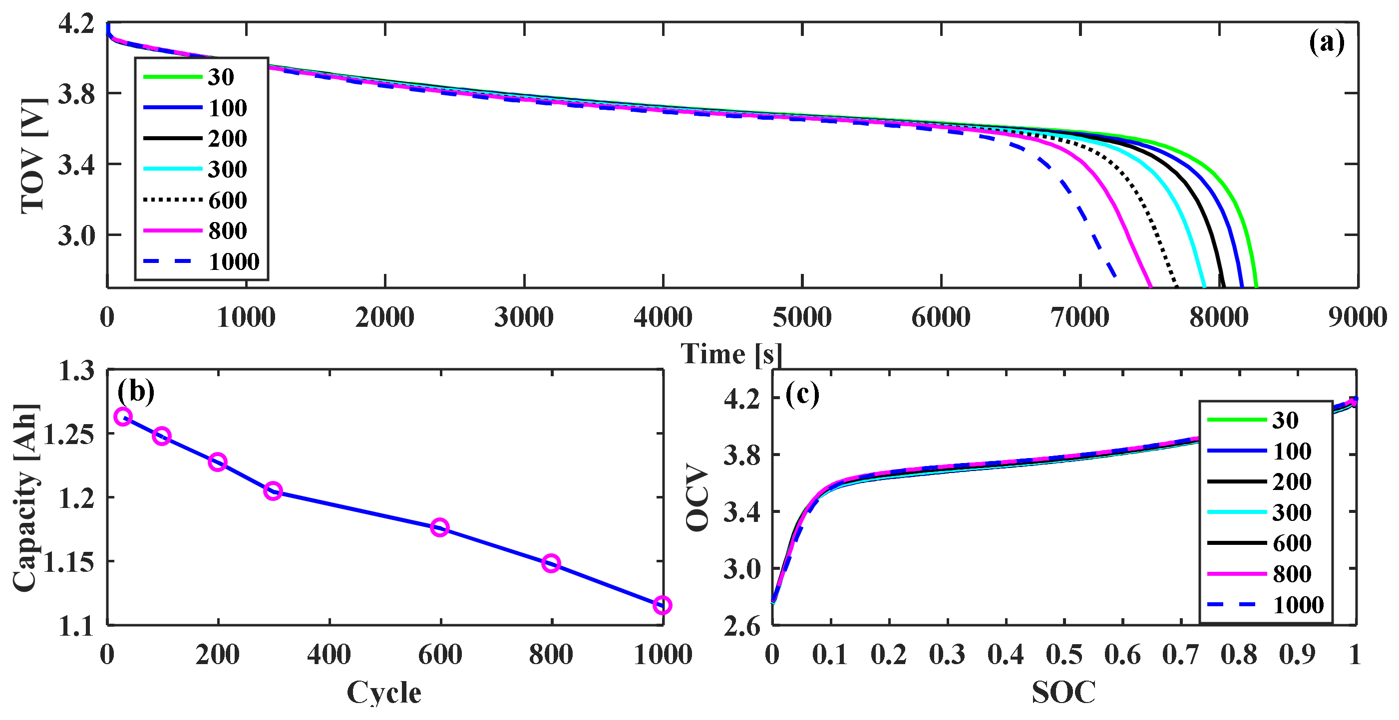
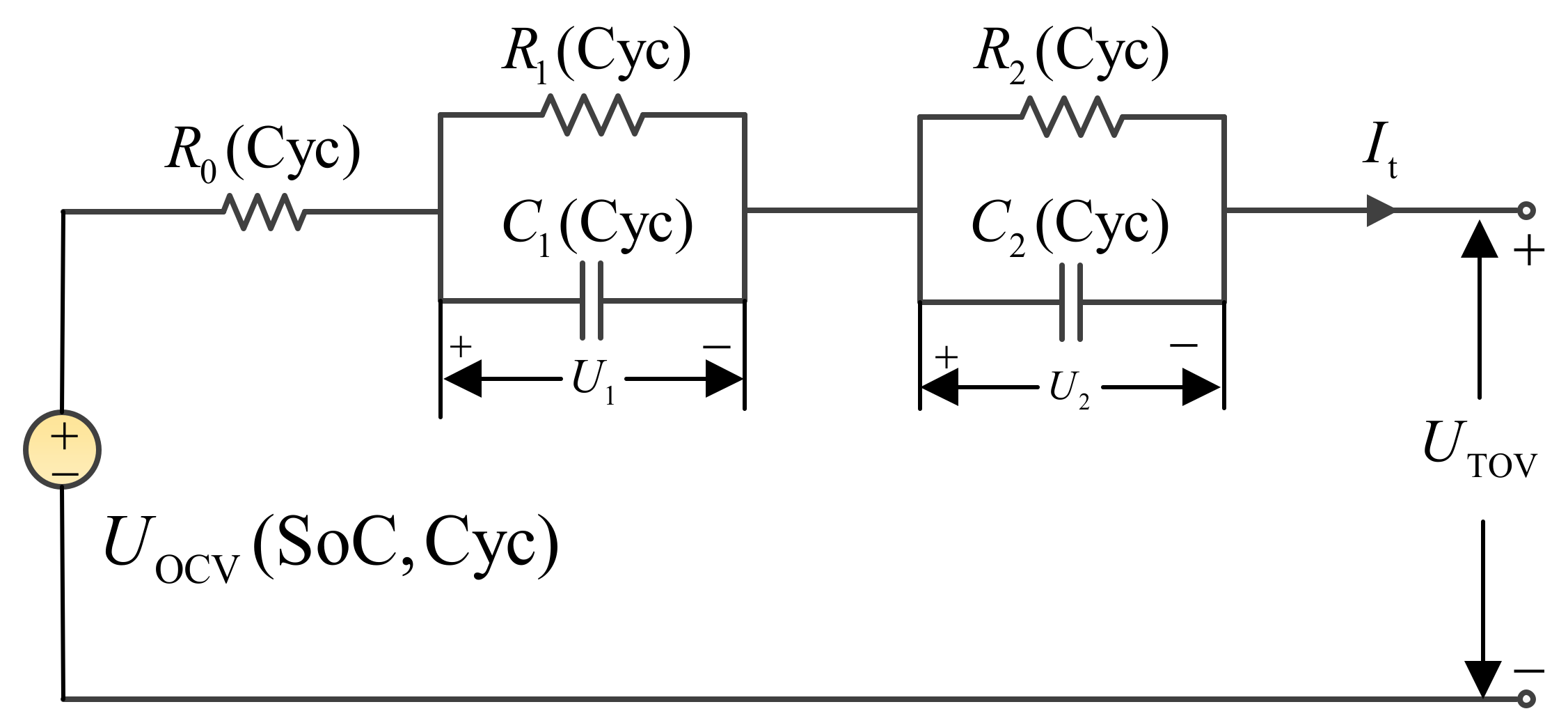
3. Battery Model Development and Parameters Estimation

In this section, we expect to carry out the model development of LIBs considering various driving cycles. It is well known that the Thevenin model and 2RC-ECM model have been extensively investigated and extensively applied in the area of battery modeling and state estimation over the past decades (see sources [8,9,10]). Apart from the ambient, the driving cycles (charging and/or discharging) may also result in some changes in battery internal states [10,35]; i.e., the capacity usually decreases the internal resistance, which affects the accuracy of battery SoC and other related statistics. Consequently, in the first place, the battery cECM shown in Figure 4 is reconstructed for battery parameters and estimation of internal states.
Unlike the previous 2RC-ECM model, battery internal statistics including R0, R1, C1, R2 and C2, along with the battery OCV are only considered to be dependent on the SoC. By contrast, it is expected that the battery OCV is regarded as a function of the battery SoC and Cyc, denoted by U OC ( SoC ,   Cyc ) , and the other five battery states R0(Cyc), R1(Cyc), C1(Cyc), R2(Cyc) and C2(Cyc) are all functions of driving cycles (Cyc); for brevity, the parameters of R0(Cyc), R1(Cyc), C1(Cyc), R2(Cyc) and C2(Cyc) are expressed as R0, R1, C1, R2 and C2 in this paper.
According to the Kirchhoff theorem, the state equation of this battery cECM is constructed as:
U ˙ 1 = I t C 1 ( Cyc ) U 1 R 1 ( Cyc ) C 1 ( Cyc ) U ˙ 2 = I t C 2 ( Cyc ) U 2 R 2 ( Cyc ) C 2 ( Cyc ) U TOV = U OC ( SoC , Cyc ) U 1 U 2 I t R 0 ( Cyc )
wherein R0 is the ohmic internal resistance, R1 and C1 are the electrochemical polarization resistance and corresponding capacitance, respectively, and R2 and C2 are the concentration polarization resistance and corresponding capacitance, respectively; U1 and U2 are the voltage across the two parallel RC (resistance- capacitor) networks, separately; Icur is the applied current (supposed positive for charge and negative for discharge); and UTOV is the terminal output voltage.
Next, by using the test profiles and the fitted OCV-SoC-Cyc function shown in Figure 3, we performed the battery parameters estimation and validation on the basis of the recursive least square algorithm (RLSM) [38,39,40]. The specific parameters’ identifications can be found in [39], published by our research group.
Alternatively, to reveal fluctuations in the related identified parameters concerning Cyc, the polynomial function is employed to fit the mathematical expressions of these five battery states with respect to Cyc, as shown in Figure 5. We observed that the magenta circle (O) denotes the identified parameter values in Table 4 from the proposed battery cECM. In contrast, the blue solid lines indicate the fitted function by curve fitting tool/MATLAB, as shown in Equation (2). It is observed from Figure 5 that each parameter of the battery cECM has a noticeable tendency to increase with the increasing Cyc. In particular, the internal resistances of R0, R1 and R2 grew faster during the low-Cyc and high-Cyc parts, and they increased very slowly during the middle-Cyc regions.
R 0 = 3.272 × 10 8 Cy c 3 4.741 × 10 5 Cy c 2 + 0.02765 × 10 8 Cyc + 83.93 R 1 = 3.215 × 10 9 Cy c 3 8.868 × 10 6 Cy c 2 + 1.107 × 10 2 Cyc + 31.49 C 1 = 3.8 × 10 7 Cy c 3 7 × 10 4 Cy c 2 + 1.0 Cyc + 419.1 R 2 = 4.159 × 10 9 Cy c 3 5.898 × 10 6 Cy c 2 + 4.229 × 10 3 Cyc + 17.34 C 2 = 6.606 × 10 6 Cy c 3 + 9.568 × 10 3 Cy c 2 0.306 Cyc + 4572
Thereby, on one side, the identified parameters of this cECM under different cycles are given in Table 4 as follows:
After obtaining the battery parameters, to confirm the precision of the obtained five parameters, the measured and estimated battery TOV, together with their TOV errors under the test profiles of CCC under different driving cycles of [30, 300, 1000], are provided in Figure 6.
In Figure 6, the black solid line indicates the measured TOV, while the red solid line represents the estimated TOV based on battery cECM. It can be seen that the estimated voltages are always slightly smaller than the measured ones, and the proposed cECM can reasonably predict the TOV, which illustrates that the proposed model has better performance in reflecting lithium-ion battery external characteristics under different driving cycles. It is noted that the estimated voltages are always slightly smaller than the measured ones.

4. The Co-Estimation of Battery SoC and SoH

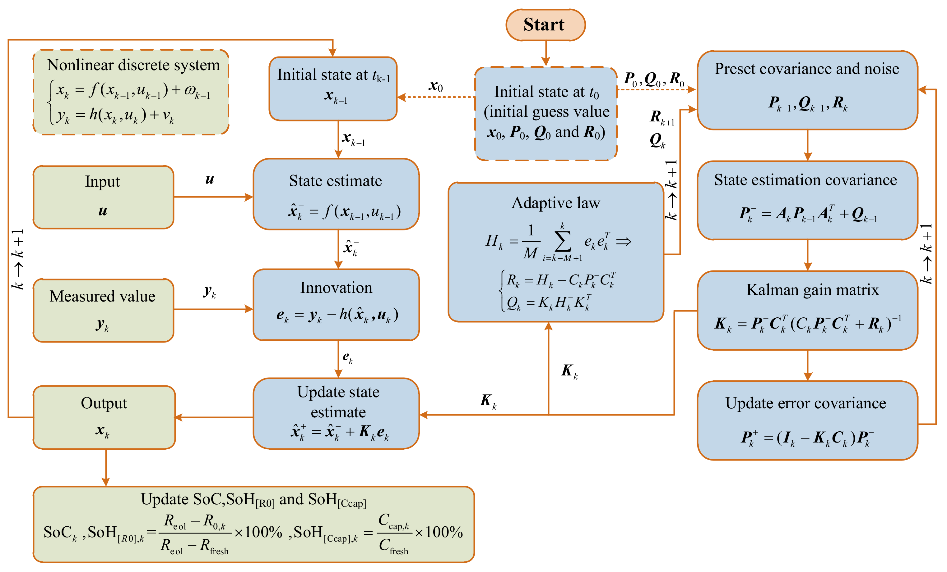
4.1. Adaptive Extended Kalman Filter Algorithm

Although KF and EKF have been generally employed in battery state estimation and parameter identification recently, their performance is heavily dependent on the precision of the predetermined noise matrix [41,42]. However, although an EKF algorithm takes noise into account, it assumes that the noise does not change, which is obviously not practical. Thus, an AEKF algorithm based on covariance matching is applied to the co-estimation of SoC/SoH. To implement the AEKF algorithm to estimate battery SoC and SoH, a general framework for the nonlinear discrete-time state and measurement dynamic equations is as follows:
x k = f ( x k 1 , u k 1 ) + ω k 1 y k = h ( x k , u k ) + v k
where xk and yk denote the system state vector and the system measurement output vector, respectively; f(xk−1, uk−1) and h(xk, uk) represent the system state function and the system measurement function, respectively; ω k 1 is Gaussian process noise sequence; Qk−1 is the covariance; vk is Gaussian measurement noise sequence; Rk is the covariance; and k is the time step.
To apply an AEKF approach to estimation of battery states, we need discrete Equation (1) as follows:
U 1 , k = exp ( T s / τ 1 ) U 1 , k 1 + R 1 ( 1 exp ( T s / τ 1 ) ) I cur , k 1 U 2 , k = exp ( T s / τ 2 ) U 2 , k 1 + R 2 ( 1 exp ( T s / τ 2 ) ) I cur , k 1 U t , k = U OC ( SoC , Cyc ) R 0 I cur , k 1 U 1 , k U 2 , k
where τ1 and τ2 are the time constants, τ1 = R1C1 and τ2 = R2C2. Ts is the sampling time.
Next, we define the system state vector as x k = SoC k U 1 , k U 2 , k R 0 , k 1 C α , k T ; the system output variable as y k = U TOV , k ; and the system input variable as u k = I cur , k . Then, the discrete state-space form of Equation (1) can be rewritten as:
x k = A x k 1 + B u k 1 + ω k 1 y k = C x k + v k
where A, B and C denote the system matrices and are defined as follows:
A = 1 0 0 0 η I T s / 3600 0 exp ( T s / τ 1 ) 0 0 0 0 0 exp ( T s / τ 2 ) 0 0 0 0 0 1 0 0 0 0 0 1 , B = 0 R 1 · ( 1 exp ( T s / τ 1 ) ) R 2 · ( 1 exp ( T s / τ 2 ) ) 0 0 C = α 1 1 I 0 T
Herein, the SoC can be calculated by the following equation:
SoC k = SoC k 1 I k η T s C α , k
where SoCk represents the observation of SoC at time step k; C α , k represents the observation of Ca in time step k at the current aging levels; η represents the Coulomb efficiency; and It,k denotes the applied current.
In addition, according to Equation (5), the battery SoH characterized by the available capacity can be calculated by:
SoH [ Ccap ] , k = C cap , k C fresh × 100 %
Herein, the SoH can be characterized by the battery’s residual maximum available capacity, denoted by SoH [ Ccap ] . Then, C cap , k represents the observation of C cap in time step k at the current aging levels. Cfresh is 1.270 Ah for a new LiCoO2 cell, which represents the maximum available battery capacity at the factory.
Furthermore, the SoH can also be characterized by R0, denoted by SOH R 0 , which is expressed by
SoH [ R 0 ] , k = R eol R 0 , k R eol R fresh × 100 %
Herein, the SoH can be characterized in terms of the battery’s ohmic internal resistance (R0), denoted by SoH [ R 0 ] . Then, R 0 , k denotes the observation of R0 in time step k at the current aging levels; Rfresh is the R0 at the first cycle times; and Reol indicates the R0 at the end of the life.
Figure 7 shows the flowchart of the AEKF-based SoC/SoH co-estimation method. Note that Hk is the innovation covariance matrix; M is the window of size; x ^ k and x ^ k + denote the priori estimate and posteriori estimate of the system, respectively; P k and P k + denote the priori estimate and posteriori estimate of the state estimation covariance, respectively; e k is considered to be innovation, which indicates the difference between the measured values and observed values; I k indicates the unit matrix; and t0 indicates the initial moment of the algorithm’s calculation.
For practical applications, the computational procedure of the proposed AEKF-based co-estimation scheme is summarized in Table 5.

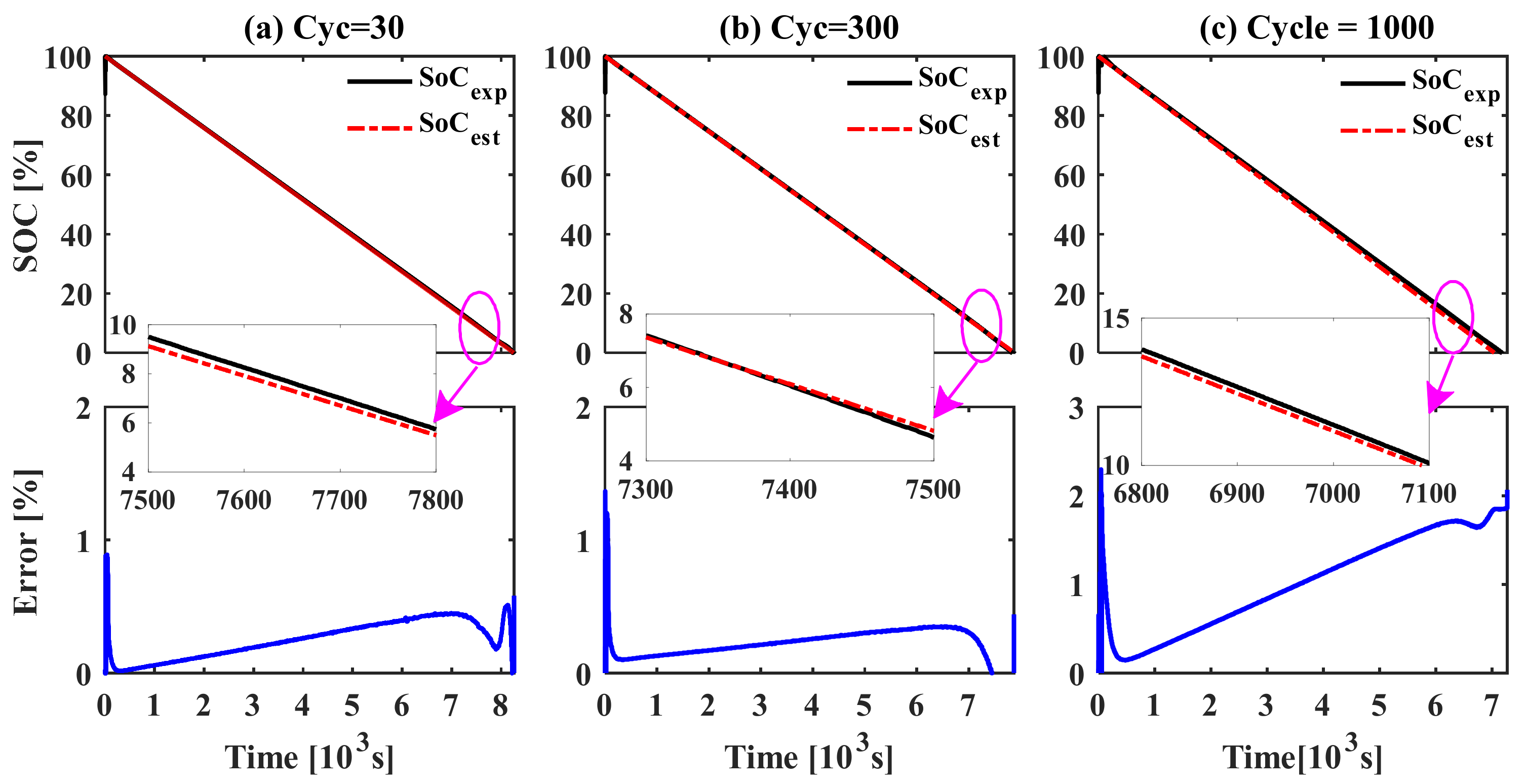
4.2. SoC Estimation Results and Discussions

Through the implementation of the AEKF-based SoC/SoH co-estimation algorithm, we can obtain the curves of the SoC estimation and SoC errors at Cyc [30, 100, 200, 300, 600, 800 and 1000] under CCC test profiles for a LiCoO2 cell. For brevity, only the curves of the SoC estimation and SoC errors at Cyc [30, 300 and 1000] are presented in Figure 8.
It is observed that the estimated SoC (SoCest) under different cycle numbers can track the experimental SoC (SoCexp) profiles well, and the maximum values of the absolute error are 0.51%, 0.38% and 2.37%, respectively, which illustrates that the co-estimation algorithm has higher accuracy in estimating the battery SoC under different aging levels. Moreover, the practical remaining capacity C cap decreases more rapidly with the increasing cycle times, and the SoC estimation errors become more fluctuated with the increasing cycle numbers.

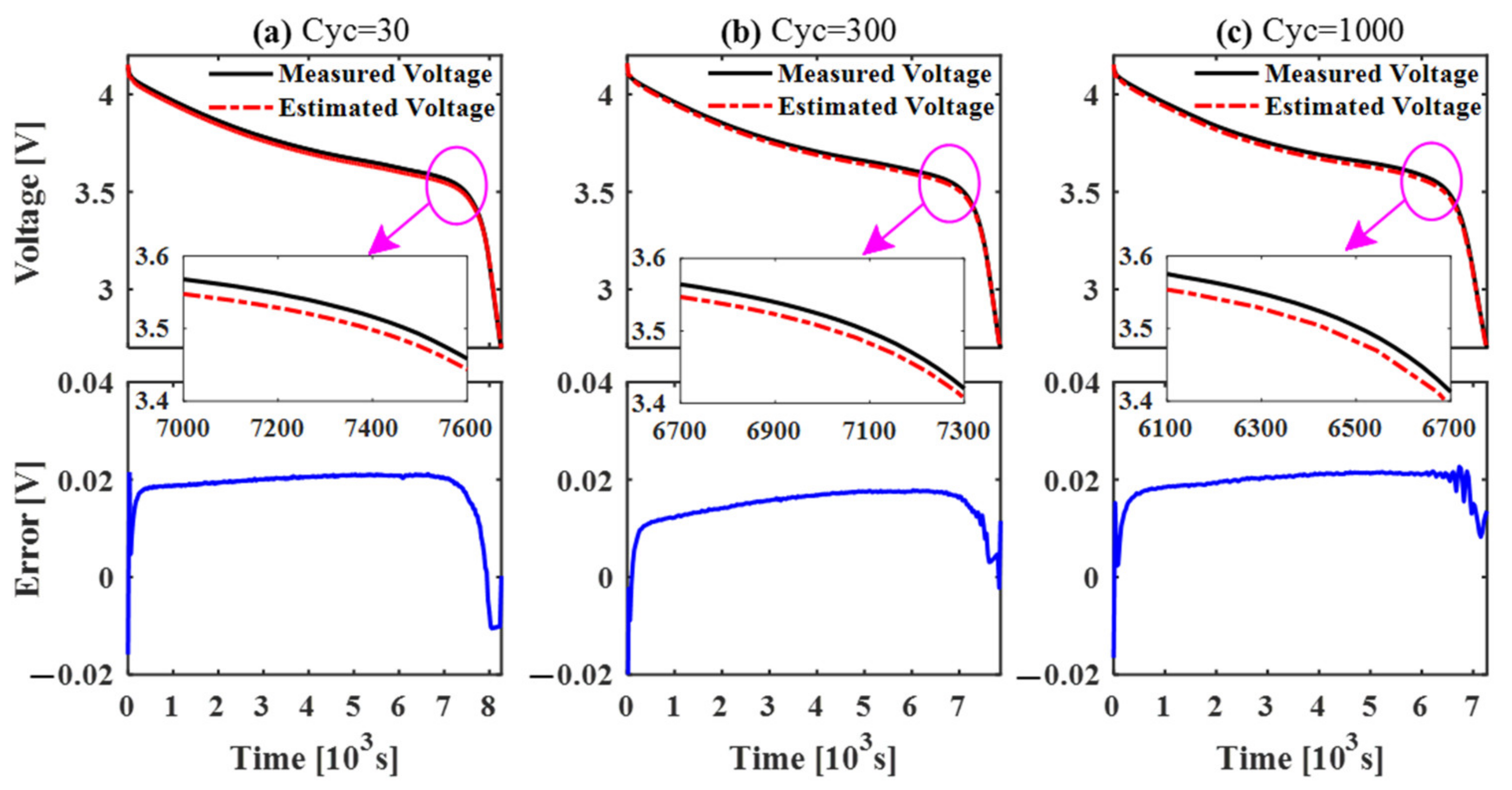
4.3. SoH Estimation Results and Discussions

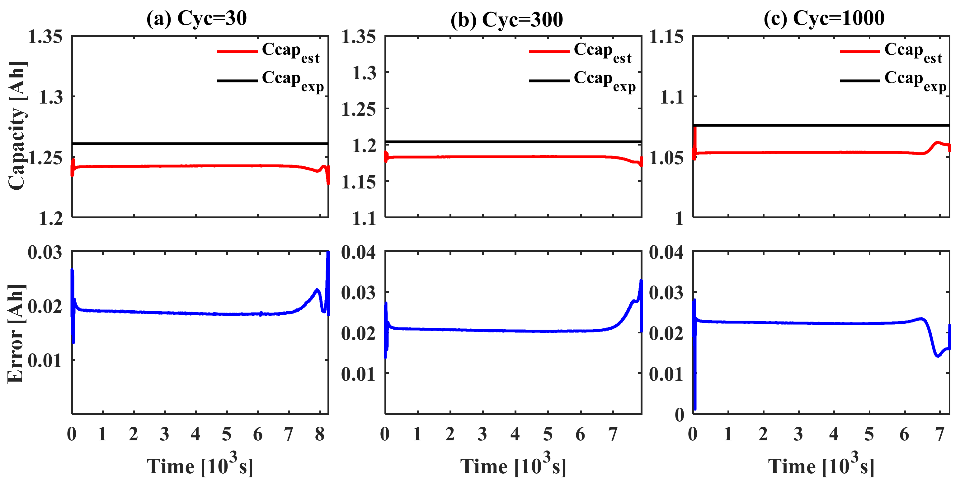
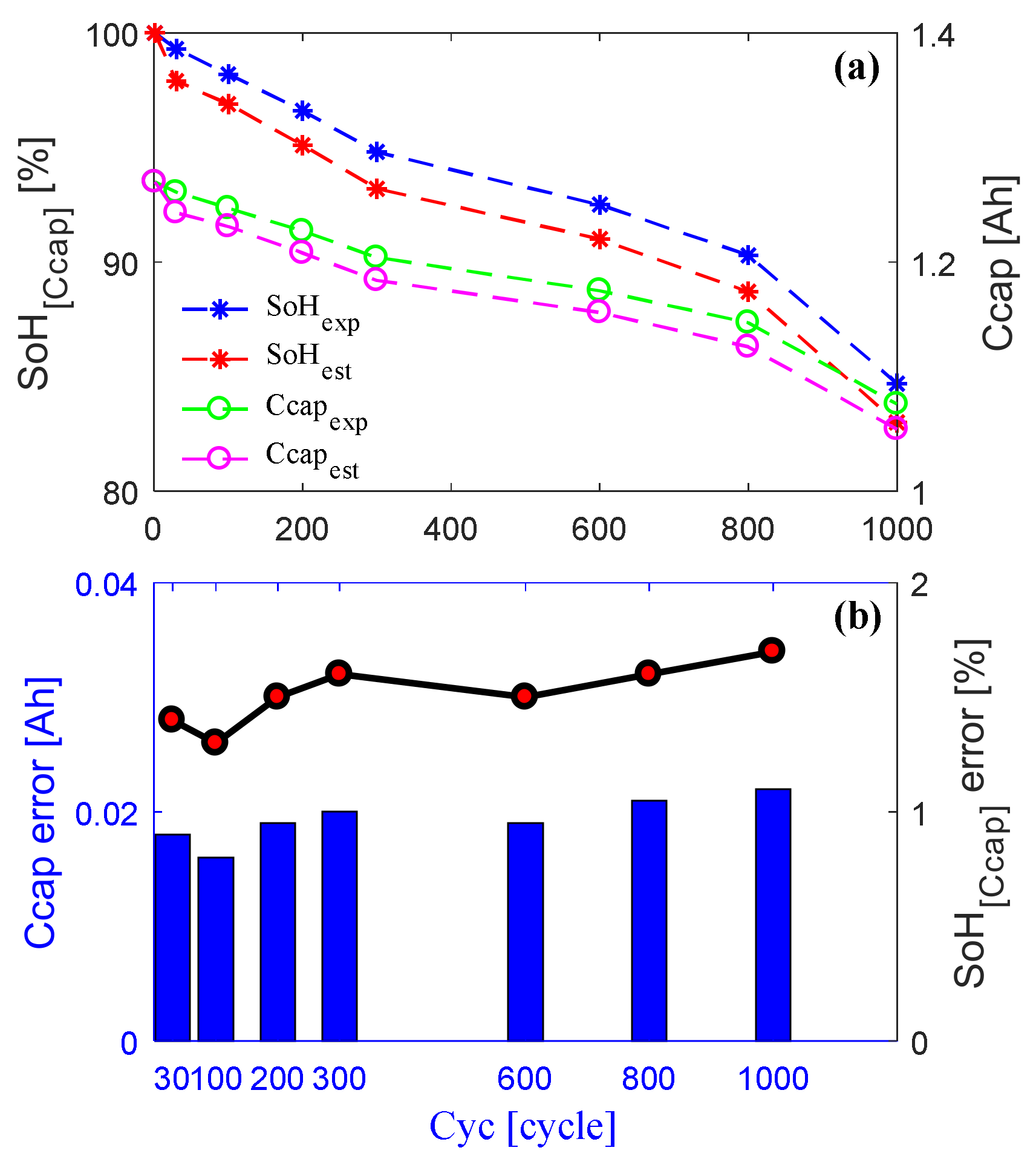
4.3.1. Capacity Estimation Results under Different Cycles

In this section, to reveal the advantages of the proposed co-estimation scheme with respect to the battery residual maximum available capacity (Cmax) estimation, the capacity estimation results and the corresponding capacity errors at Cyc [30, 300 and 1000] under a CCC test profile are provided in Figure 9. Note that the black solid line indicates the battery’s maximum available capacity value under the current cycle times, which is derived from Figure 3b in Section 2 and is used as the reference capacity value (Ccapexp) herein; the red solid line represents the estimated battery capacity (Ccapest) based on the AEKF estimator.
It is observed in Figure 9 that Ccapest, obtained by the AEKF, can well track the profile of Ccapexp, and the averaged values of absolute error are 0.018 Ah, 0.020 Ah and 0.022 Ah, respectively, which illustrates that the co-estimation algorithm has better performance in a battery’s Cmax estimation under different aging cycle levels.
Additionally, the averaged values of the estimated capacity at [30, 100, 200, 300, 600, 800, 1000] cycle numbers are extracted and taken as the values of C cap , k in Equation (7), of which Cfresh is the maximal remaining capacity at the first cycle. Afterwards, we can calculate SoH[Ccap] under different cycle times as shown in Figure 10a. It is important to point out that the green dashed line and circle represent the reference capacity value Ccapexp; the blue dashed line and asterisk indicate SoHexp; the magenta dashed line and circle represent the averaged values of the estimated battery capacity in Figure 9, denoted by Ccapest; and the red dashed line and asterisk indicate SoHest, calculated by Equation (7), where C cap , k is Ccapest. It is observed in Figure 10a that the estimated value of SoHest (i.e., red dashed line) with the AEKF can track the referenced value of SoHexp (i.e., blue dashed line) well.
Conversely, as displayed in Figure 10b, the black line indicates the SoH[Ccap] absolute error, which is 1.3%, 1.6% and 1.7% under [30, 300 and 1000] aging levels, which further illustrates that the co-estimation algorithm has higher accuracy in estimating a battery’s SoH[Ccap] under different aging levels.

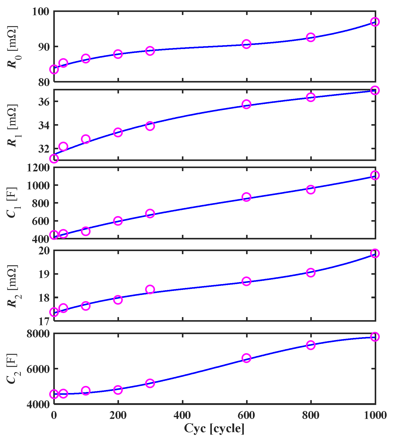
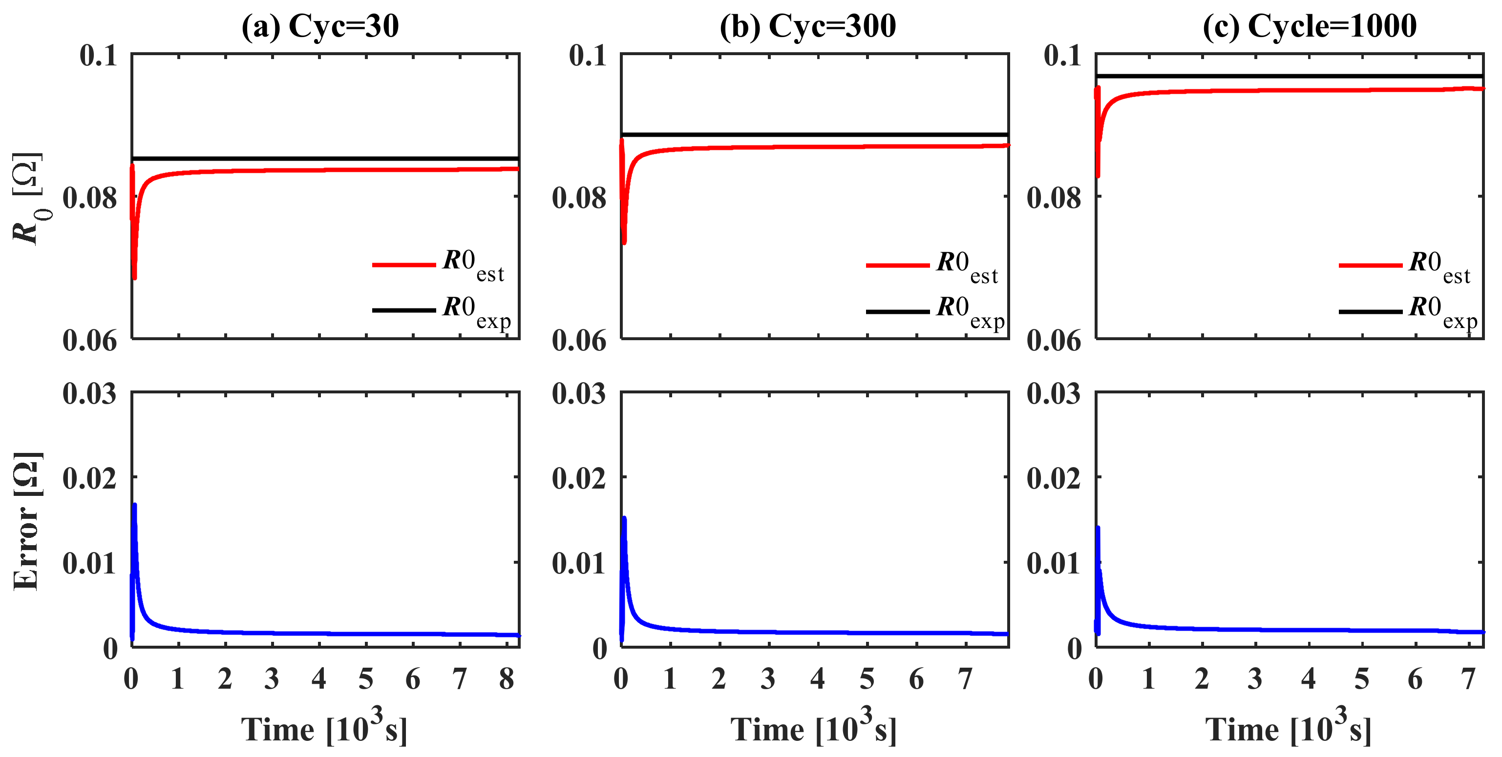
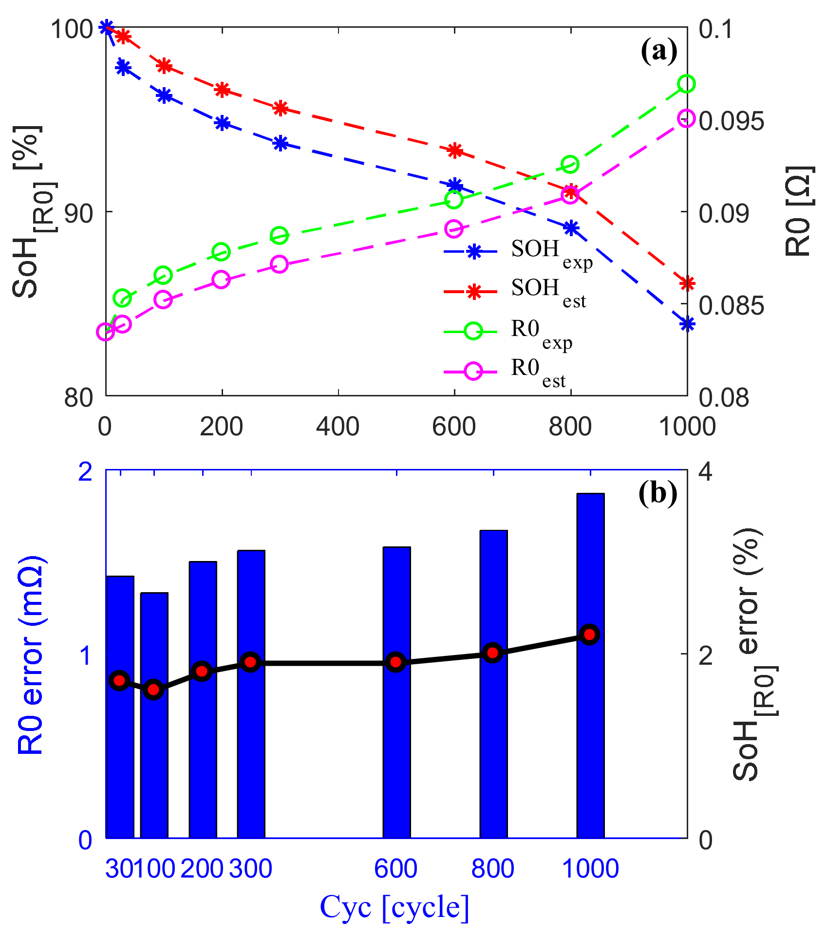
4.3.2. Resistance Estimation Results under Different Cycles

Similarly, the estimation of R0 and its errors at Cyc [30, 300 and 1000] under a CCC test profile are provided in Figure 11. Herein, the black solid line indicates the values of R0 under the current cycle times, which are derived from Table 4 in Section 3 and are employed as the reference value R0exp, while the red solid line represents the estimated battery ohmic internal resistance R0est based on the AEKF estimator. It is observed in Figure 11 that R0est with the AEKF can track R0exp profiles well, and the averaged values of absolute error are 1.42 mΩ, 1.56 mΩ and 1.87 mΩ, respectively, which illustrates that the co-estimation algorithm has better performance in estimating battery R0 under different aging levels.
In terms of the above estimations, we can obtain the battery internal resistances at Cyc [30, 100, 200, 300, 600, 800 and 1000], among which the averaged value of R0 at each cycle is taken as the value of R 0 , k in Equation (8), noting that Rfresh is the actual resistance value after the first cycle and Reol is the resistance value when the battery lifespan ends. As such, according to Equation (8), we can calculate the estimated SoH at different cycle numbers, denoted by SOH[R0]; this is presented in Figure 12a. Similarly, the green dashed line and circle denote the reference ohmic internal resistance value R0exp, which is derived from Table 4 in Section 3. The blue dashed line and asterisk indicate the values of SOHexp calculated by Equation (8), where R 0 , k means R0exp. In addition, the magenta dashed line and circle represent the averaged values of the estimated R0 in Figure 11, denoted by R0est, and the red dashed line and asterisk indicate the SOHest calculated by Equation (8), where R 0 , k is R0est. It is observed from Figure 12a that the estimated value of SoHest (i.e., red dashed line) with an AEKF can track the referenced value SoHexp (i.e., blue dashed line) well.
Particularly, as illustrated in Figure 12b, the black line indicates the SOH[R0] absolute error, which is 1.7%, 1.9% and 2.2% under [30, 300 and 1000] aging levels. This manifests that the proposed co-estimation algorithm has higher precision in battery SOH[R0] estimation under different aging levels.

5. Conclusions

The decommissioned lithium-ion power battery was taken as the investigation object in this paper, and the screening method and process for the second use of the decommissioned battery was formulated. Aiming at the need to establish a model before SOC/SOH estimation for decommissioned LIBs, as well as to identify the model parameters, a battery state estimator based on an AEKF was proposed to study the co-estimation of battery SOC/SOH for EVs’ power battery packs.
The accuracy co-estimation of SoC and SoH play a vital role in developing advanced BMS with efficient charging management, safety management, lifespan management and endurance mileage for EVs. First, by performing a battery accelerated aging test and analyzing the battery external characteristic differences, an enhanced second-order equivalent circuit model considering different cycle times is built up. Then, based on this cECM of LIBs, the RLS approach is employed to estimate the model parameters, and the correctness of the identified parameters is validated in MATLAB/Simulink platform. Next, a class of AEKF-based battery state estimators is developed to realize the co-estimation of battery SoC and SoH in the case of CCC test profiles under different cycle times, and the corresponding simulation investigations of this co-estimator are carried out. The results indicate that the proposed SoC/SoH co-estimation scheme can predict battery SoC and SoH well, wherein the peak value of SoC errors is less than 2.2%. While the maximum errors of the available capacity and its corresponding SoH[Ccap] are less than 0.02 Ah and 1.7%, respectively, the maximal errors of the estimated R0 and SoH[R0] are less than 1.58 mΩ and 2.2%, respectively.
It is worth noting that the SOC/SOH co-estimation scheme proposed in this paper can satisfactorily provide a valuable reference for the screening of decommissioned batteries in practical applications.

Author Contributions

Conceptualization, N.J.; methodology, N.J.; validation, H.P.; formal analysis, N.J. and H.P.; resources, H.P.; writing—review and editing H.P. All authors have read and agreed to the published version of the manuscript.

Funding

This research was funded by the Foundation of Beilin Science and Technology Bureau, Xi’an City (GX2018).

Conflicts of Interest

The authors declare no conflict of interest.

References

  1. Xia, B.; Chen, G.; Zhou, J.; Yang, Y.; Huang, R.; Wang, W.; Wang, H. Online parameter identification and joint estimation of the State of charge and the state of health of lithium-ion batteries considering the degree of polarization. Energies 2019, 12, 2939. [Google Scholar] [CrossRef] [Green Version]
  2. Sun, T.F.; Xia, B.Z.; Liu, Y.F.; Lai, Y.; Zheng, W.; Wang, H.; Wang, M. A novel hybrid prognostic approach for remaining useful life estimation of lithium-ion batteries. Energies 2019, 12, 3678. [Google Scholar] [CrossRef] [Green Version]
  3. Huang, B.; Liu, C.H.; Hu, M.H.; Li, L.; Jin, G.; Yang, H.Q. Joint Estimation of SOC and Available Capacity of Power Lithium-Ion Battery. Electronics 2022, 11, 151. [Google Scholar] [CrossRef]
  4. Xu, Y.; Hu, M.; Fu, C.; Cao, K.; Su, Z.; Yang, Z. State of charge estimation for lithium-ion batteries based on temperature-dependent second-order RC model. Electronics 2019, 8, 1012. [Google Scholar] [CrossRef] [Green Version]
  5. Dotoli, M.; Rocca, R.; Giuliano, M.; Nicol, G.; Parussa, F.; Baricco, M.; Sgroi, M.F. A Review of Mechanical and Chemical Sensors for Automotive Li-Ion Battery Systems. Sensors 2022, 22, 1763. [Google Scholar] [CrossRef]
  6. Yu, H.F.; Lu, R.G.; Zhu, C.B. State of Charge Estimation Calibration for Ni-MH Battery Based on Ampere-Hour Method. Trans. China Electrotech. Soc. 2012, 27, 12–18. [Google Scholar]
  7. Bao, H.; Yu, Y. State of Charge Estimation Calibration Based on Ampere-Hour Method. Comput. Simul. 2013, 30, 148–151, 159. [Google Scholar]
  8. Deng, Y.; Hu, Y.L.; Cao, Y. An improved algorithm of soc testing based on open-circuit voltage-ampere hour method. In Intelligent Computing in Smart Grid and Electrical Vehicles; Springer: Berlin/Heidelberg, Germany, 2014; pp. 258–267. [Google Scholar]
  9. Lee, S.; Kim, J.; Lee, J. State-of-charge and capacity estimation of lithium-ion battery using a new open-circuit voltage versus state-of-charge. J. Power Sources 2008, 185, 1367–1373. [Google Scholar] [CrossRef]
  10. Xing, Y.J.; He, W.; Pecht, M. State of charge estimation of lithium-ion batteries using the open-circuit voltage at various ambient temperatures. Appl. Energy 2014, 113, 106–115. [Google Scholar] [CrossRef]
  11. Enache, B.A.; Diaconescu, E. Estimating a battery State of Charge using neural networks. In Proceedings of the 2014 International Symposium on Fundamentals of Electrical Engineering (ISFEE), Bucharest, Romania, 28–29 November 2014; pp. 1–6. [Google Scholar]
  12. Xia, B.Z.; Cui, D.Y.; Sun, Z. State of charge estimation of lithium-ion batteries using optimized Levenberg-Marquardt wavelet neural network. Energy 2018, 153, 694–705. [Google Scholar] [CrossRef]
  13. Charkhgard, M.; Farrokhi, M. State-of-Charge Estimation for Lithium-Ion Batteries Using Neural Networks and EKF. IEEE Trans. Ind. Electron. 2010, 57, 4178–4187. [Google Scholar] [CrossRef]
  14. Luo, J.Y.; Peng, J.K.; He, H.W. Lithium-ion battery SOC estimation study based on Cubature Kalman filter. Energy Procedia 2019, 158, 3421–3426. [Google Scholar] [CrossRef]
  15. Shrivastava, P.; Soon, T.K.; Idris, M.Y.I.B.; Mekhilef, S. Overview of model-based online state-of-charge estimation using Kalman filter family for lithium-ion batteries. Renew. Sustain. Energy Rev. 2019, 113, 109233. [Google Scholar] [CrossRef]
  16. Sun, H.H.; Bi, J.; Shao, S. The State of Charge Estimation of Lithium Battery in Electric Vehicle Based on Extended Kalman Filter. Adv. Mater. Res. 2014, 953–954, 796–799. [Google Scholar] [CrossRef]
  17. Sgroi, M.F.; Dotoli, M.; Giuliano, M.; Nicol, G.; Parussa, F.; Rocca, R. Smart batteries: Requirements of the automotive world. In Proceedings of the 2021 IEEE International Workshop on Metrology for Automotive (MetroAutomotive), Bologna, Italy, 2–3 July 2021; pp. 42–47. [Google Scholar]
  18. Wu, J.; Wang, Y.J.; Zhang, X. A novel state of health estimation method of Li-ion battery using group method of data handling. J. Power Sources 2016, 327, 457–464. [Google Scholar] [CrossRef]
  19. Li, X.; Wang, Z.; Zhang, L. State-of-health estimation for Li-ion batteries by combing the incremental capacity analysis method with grey relational analysis. J. Power Sources 2019, 410–411, 106–114. [Google Scholar] [CrossRef]
  20. Hu, C.; Youn, B.D.; Chung, J. A multiscale framework with extended Kalman filter for lithium-ion battery SOC and capacity estimation. Appl. Energy 2012, 92, 694–704. [Google Scholar] [CrossRef]
  21. Xing, Y.; Ma, E.W.M.; Tsui, K.L. An ensemble model for predicting the remaining useful performance of lithium-ion batteries. Microelectron. Reliab. 2013, 53, 811–820. [Google Scholar] [CrossRef]
  22. Wu, J.; Zhang, C.; Chen, Z.J. An online method for lithium-ion battery remaining useful life estimation using importance sampling and neural networks. Appl. Energy 2016, 173, 134–140. [Google Scholar] [CrossRef]
  23. Yang, D.; Wang, Y.; Pan, R. A Neural Network Based State-of-Health Estimation of Lithium-ion Battery in Electric Vehicles. Energy Procedia 2017, 105, 2059–2064. [Google Scholar] [CrossRef]
  24. Wang, Y.Z.; Ni, Y.L.; Lu, S. Remaining Useful Life Prediction of Lithium-Ion Batteries Using Support Vector Regression Optimized by Artificial Bee Colony. IEEE Trans. Veh. Technol. 2019, 68, 9543–9553. [Google Scholar] [CrossRef]
  25. Wei, J.W.; Dong, G.Z.; Chen, Z.H. Remaining Useful Life Prediction and State of Health Diagnosis for Lithium-Ion Batteries Using Particle filter and Support Vector Regression. IEEE Trans. Ind. Electron. 2018, 65, 5634–5643. [Google Scholar] [CrossRef]
  26. Zheng, C.; Mi, C.C.; Fu, Y. Online Battery State of Health Estimation Based on Genetic Algorithm for Electric and Hybrid Vehicle Applications. J. Power Sources 2013, 240, 184–192. [Google Scholar]
  27. Zhang, X.; Wang, Y.; Liu, C.H. A novel approach of battery pack state of health estimation using artificial intelligence optimization algorithm. J. Power Sources 2018, 376, 191–199. [Google Scholar] [CrossRef]
  28. He, W.; Williard, N.; Osterman, M. Remaining useful performance analysis of batteries. In Proceedings of the 2011 IEEE Conference on Prognostics and Health Management, Denver, CO, USA, 20–23 June 2011; pp. 1–6. [Google Scholar]
  29. Lyu, Z.Q.; Gao, R.J. A model-based and data-driven joint method for state-of-health estimation of lithium-ion battery in electric vehicles. Int. J. Energy Res. 2019, 43, 7956–7969. [Google Scholar] [CrossRef]
  30. He, W.; Williard, N.; Osterman, M.; Pecht, M. Prognostics of lithium-ion batteries based on Dempster-Shafer theory and the Bayesian Monte Carlo method. J. Power Sources 2011, 196, 10314–10321. [Google Scholar] [CrossRef]
  31. Zhang, C.B.; Yu, X.W.; Dong, G.Z. A method for remaining discharge time prediction of lithium-ion batteries under dynamic uncertainty. Int. J. Energy Res. 2019, 43, 1760–1774. [Google Scholar] [CrossRef]
  32. Liang, K.Z.; Zhang, Z.S.; Liu, P. Data-driven Ohmic Resistance Estimation of Battery Packs for Electric Vehicles. Energies 2019, 12, 4772. [Google Scholar] [CrossRef] [Green Version]
  33. Wu, Y.T.; Xue, Q.; Shen, J.W. State of Health Estimation for Lithium-ion Batteries Based on Healthy Featuresand Long Short-term Memory. IEEE Access 2020, 8, 28533–28547. [Google Scholar] [CrossRef]
  34. Li, X.Y.; Wang, Z.P.; Zhang, L. Co-estimation of capacity and state-of-charge for lithium-ion batteries in electric vehicles. Energy 2019, 174, 33–44. [Google Scholar] [CrossRef]
  35. Zou, Y.; Hu, X.S.; Ma, H.M. Combined State of Charge and State of Health estimation over lithium-ion battery cell cycle lifespan for electric vehicles. J. Power Sources 2015, 273, 793–803. [Google Scholar] [CrossRef]
  36. Shen, P.; Ouyang, M.G.; Lu, L.G. The Co-estimation of State-of-Charge, State-of-Health and State-of-Function for Lithium-ion batteries in Electric Vehicles. IEEE Trans. Veh. Technol. 2018, 67, 92–103. [Google Scholar] [CrossRef]
  37. Du, J.N.; Liu, Z.T.; Wang, Y.Y. An adaptive sliding mode observer for lithium-ion battery state of charge and state of health estimation in electric vehicles. Control. Eng. Pract. 2016, 54, 81–90. [Google Scholar] [CrossRef]
  38. Pang, H.; Mou, L.J.; Guo, L. Parameter identification and state-of-charge estimation approach for enhanced lithium-ion battery equivalent circuit model considering influence of ambient temperatures. Chin. Phys. B 2019, 28, 108201. [Google Scholar] [CrossRef]
  39. Pang, H.; Guo, L.; Wu, L.X. An enhanced temperature-dependent model and state-of-charge estimation for a Li-Ion battery using extended Kalman filter. Int. J. Energy Res. 2020, 44, 7254–7267. [Google Scholar] [CrossRef]
  40. Dai, H.F.; Wei, X.Z.; Sun, Z.C. Recursive Parameter Identification of Lithium-Ion Battery for EVs Based on Equivalent Circuit Model. J. Comput. Theor. Nanosci. 2013, 10, 2813–2818. [Google Scholar] [CrossRef]
  41. Xia, B.Z.; Zheng, W.H.; Zhang, R.F. A Novel Observer for Lithium-lon Battery State of Charge Estimation in Electric Vehicles Based on a Second-order Eguivalent Circuit Model. Energies 2017, 10, 1150. [Google Scholar] [CrossRef]
  42. Yang, S.C.; Deng, C.; Zhang, Y.L.; He, Y. State of Charge Estimation for Lithium-ion Battery with a Temperature-compensated Model. Energies 2017, 10, 1560. [Google Scholar] [CrossRef] [Green Version]
Figure 1. The framework for determining second-use power LIBs.
Electronics 11 01789 g001
Figure 2. Schematic of battery experimental setup.
Electronics 11 01789 g002
Figure 3. (a) Constant current discharge curves; (b) maximum available capacity curves; and (c) the OCV-SOC curves at different cycle times.
Electronics 11 01789 g003
Figure 4. The schematic of battery cECM.
Electronics 11 01789 g004
Figure 5. The variations of parameters vs. Cyc by curve fitting method.
Electronics 11 01789 g005
Figure 6. The validation results at (a) Cyc = 30, (b) Cyc = 300 and (c) Cyc = 1000 in the CCC test profile.
Electronics 11 01789 g006
Figure 7. The implementation flowchart of AEKF-based SoC/SoH co-estimation.
Electronics 11 01789 g007
Figure 8. SoC estimation results and SoC errors at (a) Cyc = 30, (b) Cyc = 300 and (c) Cyc = 1000 under CCC test profile.
Electronics 11 01789 g008
Figure 9. Capacity estimation results and errors at (a) Cyc = 30, (b) Cyc = 300, (c) Cyc = 1000 under CCC test profile.
Electronics 11 01789 g009
Figure 10. (a) Capacity and SoH[Ccap] estimation results; (b) capacity error and SoH[Ccap] error under different cycle times.
Electronics 11 01789 g010
Figure 11. R0 estimation results and errors at (a) Cyc = 30, (b) Cyc = 300 and (c) Cyc = 1000 under CCC test profile.
Electronics 11 01789 g011
Figure 12. (a) R0 and SoH[R0] estimation results; (b) R0 error and SoH[R0] error under different cycle times.
Electronics 11 01789 g012
Table 3. Key specifications of employed test battery cell.
ItemsSpecifications (Value)
Cell chemistryLiCoO2
Size6.6 × 33.8 × 50 mm
Rating capacity (Crat)1.35 Ah
Upper cut-off voltage4.2 V ± 50 mV
Lower cut-off voltage2.7 V
Table 4. The identified parameters of LIB cell.
CycR0/mΩR1/mΩC1/FR2/mΩC2/F
100096.8736.89110519.857783
80092.5036.3194519.037308
60090.5835.7286318.676578
30088.6433.8767818.325153
20087.7533.3359617.884775
10086.4932.7647817.624737
3085.2532.1445017.534568
0183.4131.1043817.364537
Table 5. Summary of the AEKF-based co-estimation scheme.
Step 1: Initialization. Given the initial guess values x 0 , P 0 and Q 0 .
Step 2: Time Update.
(1) State priori estimate x ^ k = f ( x k 1 , u k 1 )
(2) Error covariance P k = A k P k 1 A k T + Q k 1
Step 3: Measurement Update.
(1) Innovation e k = y k h ( x ^ k , u k )
(2) Kalman gain K k = P k C k T ( C k P k C k T + R k ) 1
(3) Adaptive law H k = 1 M i = k M + 1 k e k e k T , R k = H k C k P k C k T , Q k = K k H k K k T
(4) State estimate x ^ k + = x ^ k + K k e k
(5) Error covariance P k + = ( I k K k C k ) P k
Publisher’s Note: MDPI stays neutral with regard to jurisdictional claims in published maps and institutional affiliations.

