1. Introduction
Light-emitting diode (LED) solid-state lighting has received considerable attention recently because of its wide applicability and advantages over conventional lighting sources for monitor backlighting, traffic indicators, and general illumination. Lighting plays a key role in people’s daily lives. LEDs offer advantages such as low energy consumption, long lifetimes, small sizes, and easy production, and they are increasingly being used as replacements for incandescent lamps. LEDs are expected to become a dominant part of the next generation of lighting sources. Recently, visible light communication (VLC) has been widely studied and has become a candidate for incorporation in the IEEE 802.15.7r1 standard to achieve lighting and communications simultaneously [
1]. Through intensity modulation (IM), i.e., by modulating the light-emitting power in accordance with the transmitted data, and through direct detection (DD), i.e., by detecting the subtle light intensity variation of the transmitted optical light, VLC enables the functionality of wireless communication in a manner that is relatively simple and low in cost. Notably, this communication function does not increase power and arrangement costs, and many studies have shown that VLC systems combined with Ethernet or power line communication offer a promising solution for wireless broadband access in indoor environments [
2,
3].
Orthogonal frequency-division multiplexing (OFDM) transmission had been considered for use in VLC systems to achieve a high data transmission rate [
4]. Traditionally, the OFDM modulation and demodulation were realized by the inverse fast Fourier transform (IFFT) and the FFT, respectively. However, the traditional OFDM scheme results in complex-valued time-domain signals and cannot be directly applied to VLC transmission. As such, several studies have investigated optical OFDM schemes aimed at making the traditional OFDM scheme suitable for VLC systems [
5,
6,
7]. Basically, the real-valued bipolar signals can be obtained by using Hermitian symmetry when allocating modulated symbols to frequency domain subcarriers, after which the IFFT can be applied. By adding a direct current bias, direct current biased optical OFDM (DCO-OFDM) converts the real-valued bipolar signals to unipolar ones [
5,
6]. On the other hand, asymmetric clipping optical OFDM (ACO-OFDM) is used to impose the anti-symmetric property and directly clip the negative parts of the real-valued bipolar signals without losing information [
7]. Both DCO-OFDM and ACO-OFDM have attracted considerable attention for use in VLC systems. However, LED nonlinearity severely degrades the performance of OFDM VLC systems due to the high peak-to-average power ratio (PAPR) in OFDM signals [
8]. Normally, nonlinear devices are operated with a certain power backoff, which can be defined as the ratio of maximum saturation output to the average output. Increasing the power backoff reduces the nonlinear distortion, but cause lower power efficiency. Reducing power backoff is thus desirable, while the signal nonlinear distortion would seriously sacrifice bit error rate (BER) performance. Thus, LED nonlinearity not only reduces the power efficiency of such systems, but also degrades their BER performance. Although PAPR reduction schemes can decrease the PAPR in OFDM signals, both DCO-OFDM and ACO-OFDM signals still exhibit a considerable dynamic range and would be distorted by LED nonlinearity [
9,
10].
Given this knowledge of LED behavior, the most straightforward approach to mitigating the impact of nonlinearity would be to pre-process the DCO-OFDM signal to suppress the nonlinearity in the LED emitted signal, and to possibly enable receiver side with low complexity, which is known as transmitter digital predistortion [
11,
12,
13]. Initially, the LED characteristics can be learned by using training sequences. Subsequently, the adaptive predistorter is capable of tracking the LED characteristics due to temperature variation and aging by using the transmitted data sequences. The use of a lookup-table (LUT) that implements the inverse function against the nonlinearity of the LED constitutes the simplest predistorter [
11]. The weight required to compensate for distortion from the nonlinearity of the LED is estimated and stored in the LUT. The transmitted signal is then predistorted by multiplying the weight in the LUT closest to this signal. Based on the LUT predistorter, an adaptive algorithm was used in a previous study to dynamically learn the weights stored in the LUT by training the normalized least mean squares (NLMS) error between the transmitted signal and the distorted signal as criterion and train with a stochastic-gradient-based approach [
12], and thereafter the NLMS-based predistorter was capable of tracking changes in LED characteristics. In another study, by focusing on the fact that the distortion resulting from the LED is nonlinear, a nonlinear transformation of the input was introduced by a Chebyshev polynomial expansion and the weights were also trained by a stochastic-gradient-based approach [
13].
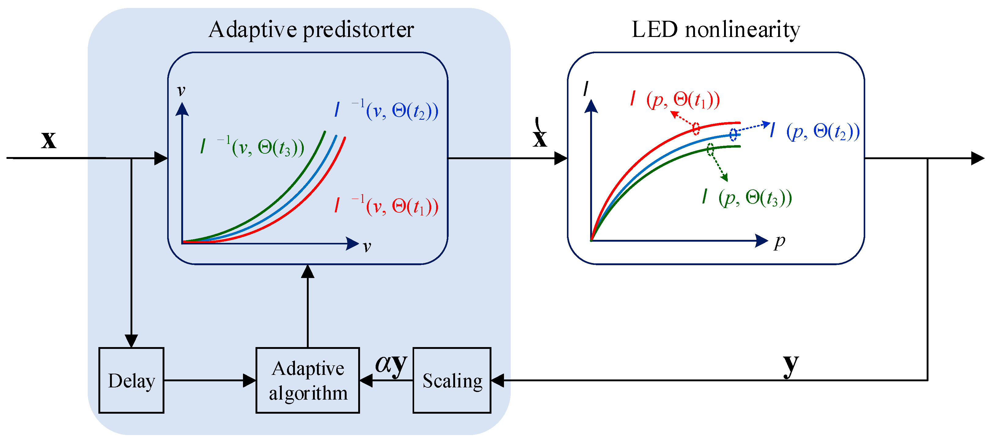
Fundamentally, using a predistorter to compensate for the LED nonlinear input power to the output illumination function
consists of cascading a block that exhibits its inverse function
in front of the LED, as shown in
Figure 1. The major issue that particularly needs to be addressed is how to accurately approximate and train the inverse function
when the LED time-variant nonlinearity function
is changed due to temperature variation, aging, or other physical changes denoted by a time-variant state vector
at time instant
. That is, the LED nonlinearity should be dynamically learned and compensated for by using its approximated inverse function with an adaptive predistorter.
As for function approximation, artificial neural networks (ANNs) are considered to be a powerful tool according to the associated and well-known universal approximation theory [
14]. It was the recognition of this power that motivated the consideration of an ANN-based predistortion algorithm in the present study. In addition, an adaptive training method was designed to make the proposed ANN-based predistorter capable of tracking the LED characteristics due to temperature variation and aging. Meanwhile, although the existing works reported in the literature were mainly based on simulations without experimental verifications [
11,
12,
13], in the present study, laboratory experiments utilizing physical devices were conducted to verify the theoretical analysis of the predistortion algorithm.
The remainder of this paper is organized as follows.
Section 2 presents a system model of adaptive predistorters for OFDM-based VLC. The proposed ANN-based predistortion is then presented in
Section 3.
Section 4 describes the simulation results with experimental verifications. Finally, the conclusions of the study are presented in
Section 5.
3. The Proposed ANN-Based Predistorter
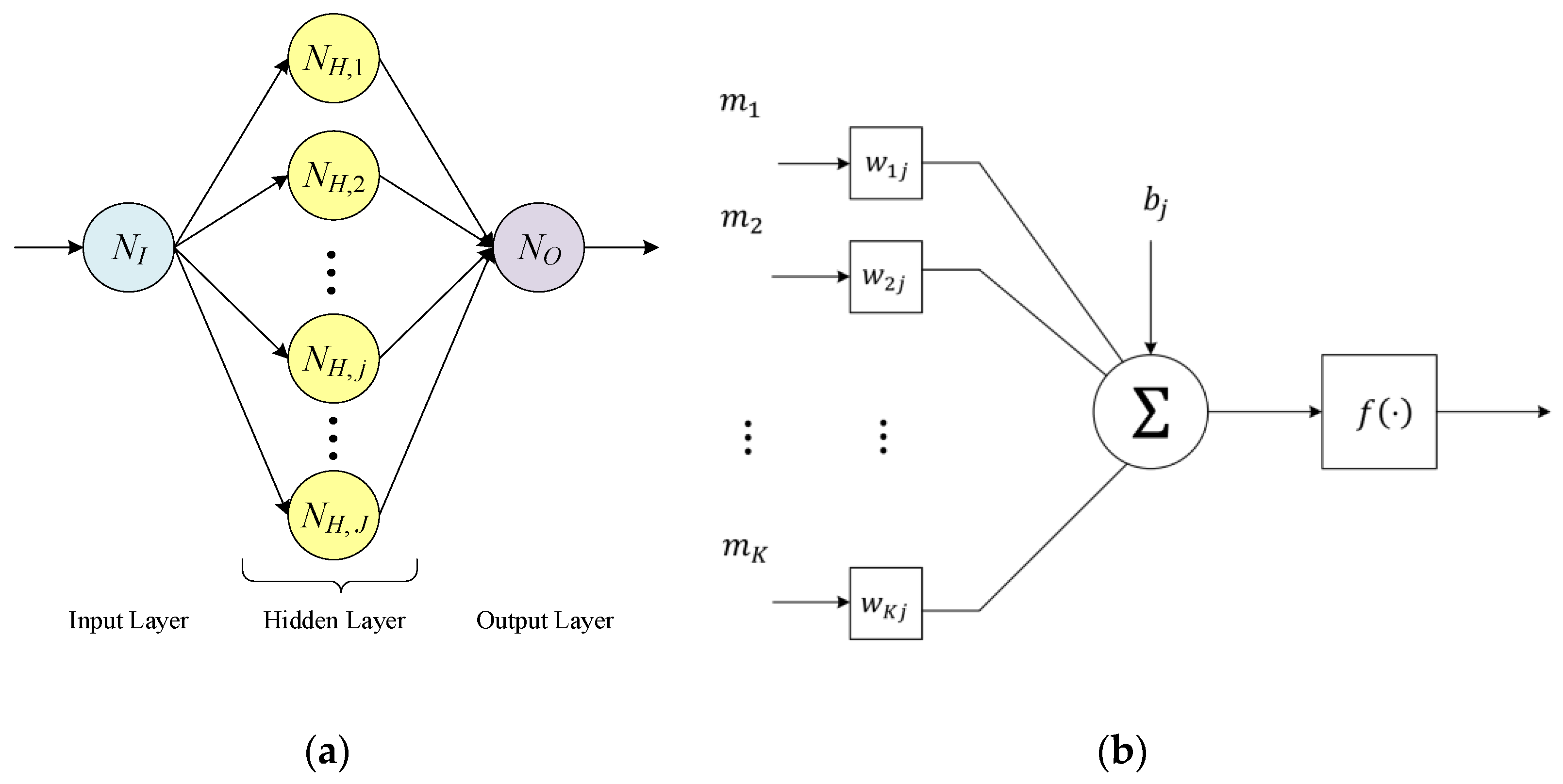
A schematic diagram of the proposed artificial neural network (ANN)-based predistorter, which has the structure of a multilayer perceptron, is shown in
Figure 3, in which
,
, and
denote the neuron in the input layer, the
-th neuron in the hidden layer, and the neuron in the output layer, respectively. ANNs were invented to serve as powerful computing systems and were inspired by the constitution of biological brains. As shown in
Figure 3a, the proposed ANN-based predistorter constitutes the input layer, one hidden layer, and the output layer. Several neurons, the basic units in an ANN, could be included in each layer. As shown in
Figure 3b, a specified neuron
would be connected with
inputs
by links with adjustable weights
, and a bias term
. An activation function
is used to introduce nonlinearity into the output of a neuron when a set of inputs and a bias term are given. Thus, the output of the
-th neuron in the hidden layer,
, is represented as follows:
where
is the input to
, and
,
, and
represent the weight, the bias value, and the activation function of
, respectively. Furthermore, the output of the neuron in the output layer,
, is represented as follows:
where
,
, and
are the weight associated with the
-th input, the bias value, and the activation function of
, respectively.
The output of the proposed ANN predistorter,
, is a cascade of nonlinear transformation of (4) and (5). When a set of training data
is applied to this ANN predistorter, its corresponding output
can be mathematically expressed as:
where
stands for the cascade function of all nonlinear transforms of the neurons in each layer and
denotes the weights and bias values in the neural network. The optimal values in
are usually learned on a training set, with known desired outputs. To start the training process,
was initially chosen at random.
A set of input values and expected values matching them should be provided to execute the training process. As shown in
Figure 1, the aim of the predistorter was to pre-emphasize the input signal
in order to maintain this pre-emphasized signal as a replica of
after the distortion by the LED nonlinearity. This indicates that the predistortion function is an inverse of the LED nonlinearity, which suggests the use of the captured outputs of the LED,
, as the inputs to the predistorter and that its corresponding outputs are
. That is:
Based on (7), the optimal values in
were trained in the present study by using a Levenberg–Marquardt (LM) backpropagation algorithm. The LM algorithm was derived from Newton’s method for the data fitting of a nonlinear function and was developed for the ANN based on the advantage that its training speed is 10 to 100 times faster than that of the usual gradient descent backpropagation method [
17,
18].
The main contributions of the proposed ANN predistorter in comparison with the methods in previous literatures are summarized as follows. First, the nonlinear ANN was studied to establish function approximation to the inverse function of the nonlinear characteristic curve of LED. Based on universal approximation theorem, ANN can approximate any continuous function and thus it can prevent the predistorter from quantization error as in [
11,
12]. Moreover, based on the relationship between the inputs and the corresponding outputs of the LED device, to adopt a real nonlinear characteristic curve of LED truly represents a more realistic LED nonlinear effect to the DCO-OFDM VLC transmission. Second, in the study, laboratory experiments utilizing physical devices were conducted to verify the theoretical analysis of the predistortion algorithm. In view of most literatures related to LED linearization only presenting their results using computer simulations, the experimental results based on the self-built DCO-OFDM VLC testbed presented in this study would make a constructive contribution for the design of the DCO-OFDM VLC transmission.
4. Simulations and Measured Results
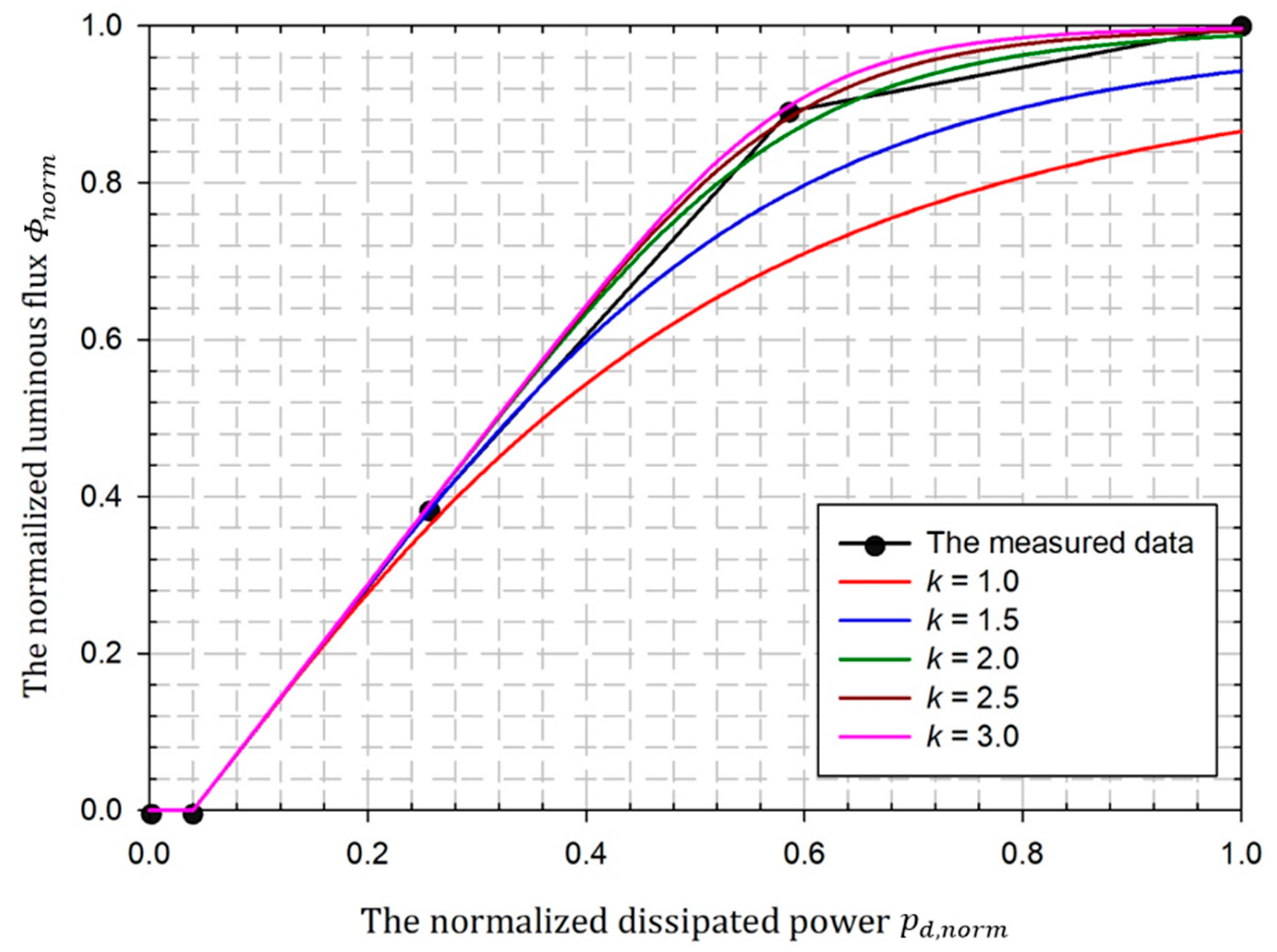
The relationship between the dissipated power and the luminous flux is used in the paper to describe the nonlinear behavior of an LED. A phosphor-based white LED (Crescent D01-A1-A33) was measured by using an integrating sphere (ISUZU SLM-12), and its dissipated power versus the output luminous flux is shown in
Table 1. To implement a unified performance simulator, a normalized LED transfer function, as plotted in
Figure 4, was used in the following performance evaluation of different considered predistortion algorithms. A Rapp-like model was adopted to fitting the normalized LED transfer function as follows [
19]:
where
is the maximum normalized dissipated power through the LED,
is the function describing the measured characteristics between the normalized dissipated power
and the normalized luminous flux
, and
is the knee factor which controls the smoothness of the transition from the linear region to the saturation region. As shown in
Figure 4, the Rapp-like model with knee factor
had a better fitting to the measured data of the considered LED and was adopted in the performance simulations of the LED nonlinearity predistorter detailed below.
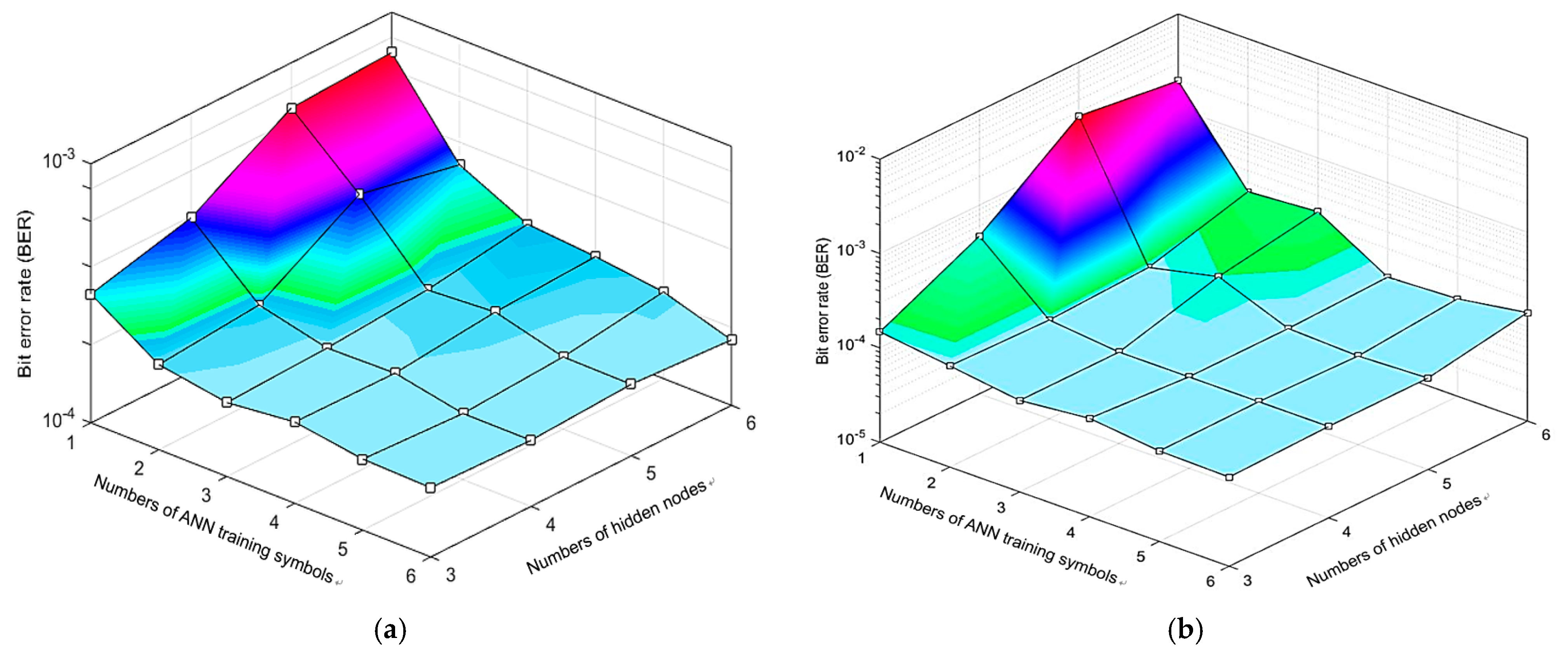
In the conducted computer simulations,
independent DCO-OFDM symbols were randomly generated with the parameters summarized in
Table 2. To find the proper settings of the number of ANN training symbols
and the number of neurons in the hidden layer of the ANN predistorter
, the BER versus the combination of the number of ANN training symbols and the number of hidden nodes are shown in
Figure 5. Generally, as can be seen in
Figure 5, the BER of the DCO-OFDM with the proposed ANN predistorter was decreased as the number of ANN training symbols was increased. The received scaling DCO-OFDM symbol
was used to train the proposed ANN predistorter. When the setting of
, it showed a limitation in effectively training the parameters in
because the distribution of the time-domain samples in one DCO-OFDM symbol might have been quite non-uniform in the domain of the desired predistorter function. When the value of
was increased, more time-domain samples in the
DCO-OFDM symbols were available, and these samples might have had a wider and uniform distribution within the domain of the desired predistorter function. As can be seen in
Figure 5, the adaptation of
seems to have been enough to effectively train the parameters in
of the predistorter function. Moreover, the simulation results presented in
Figure 5 indicated that the proposed ANN predistorter composed of a single hidden layer with 4 neurons was able to achieve a stable BER performance. Meanwhile, increasing the number of neurons in the hidden layer to more than 4 only seemed to increase the complexity of the network; thus, the number of neurons in the hidden layer
was set at 4.
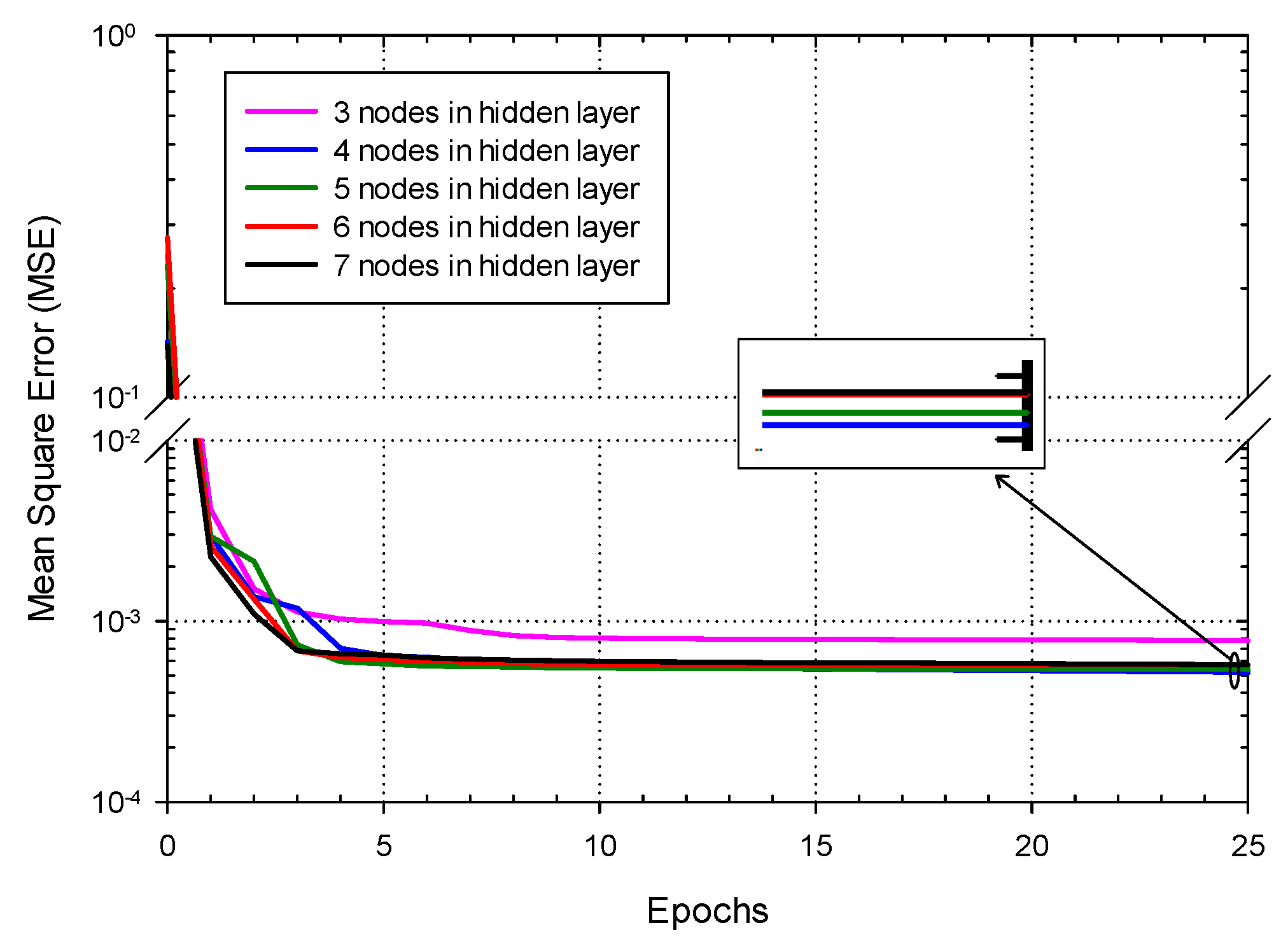
The convergence of the proposed ANN predistorter with different numbers of neurons in the hidden layer is shown in
Figure 6. Consistent with the findings of
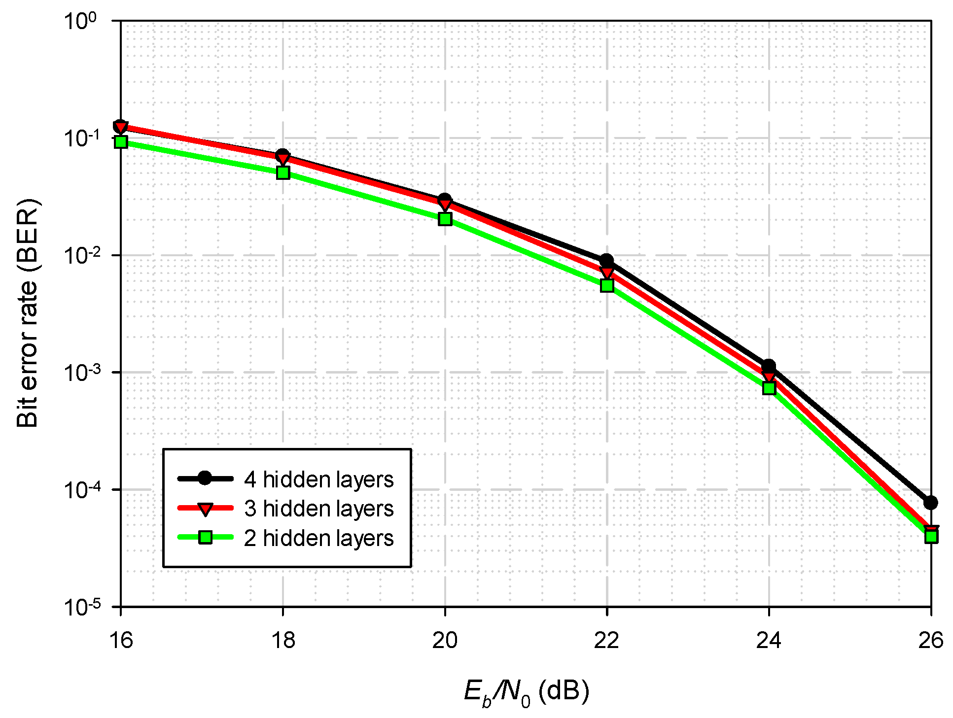
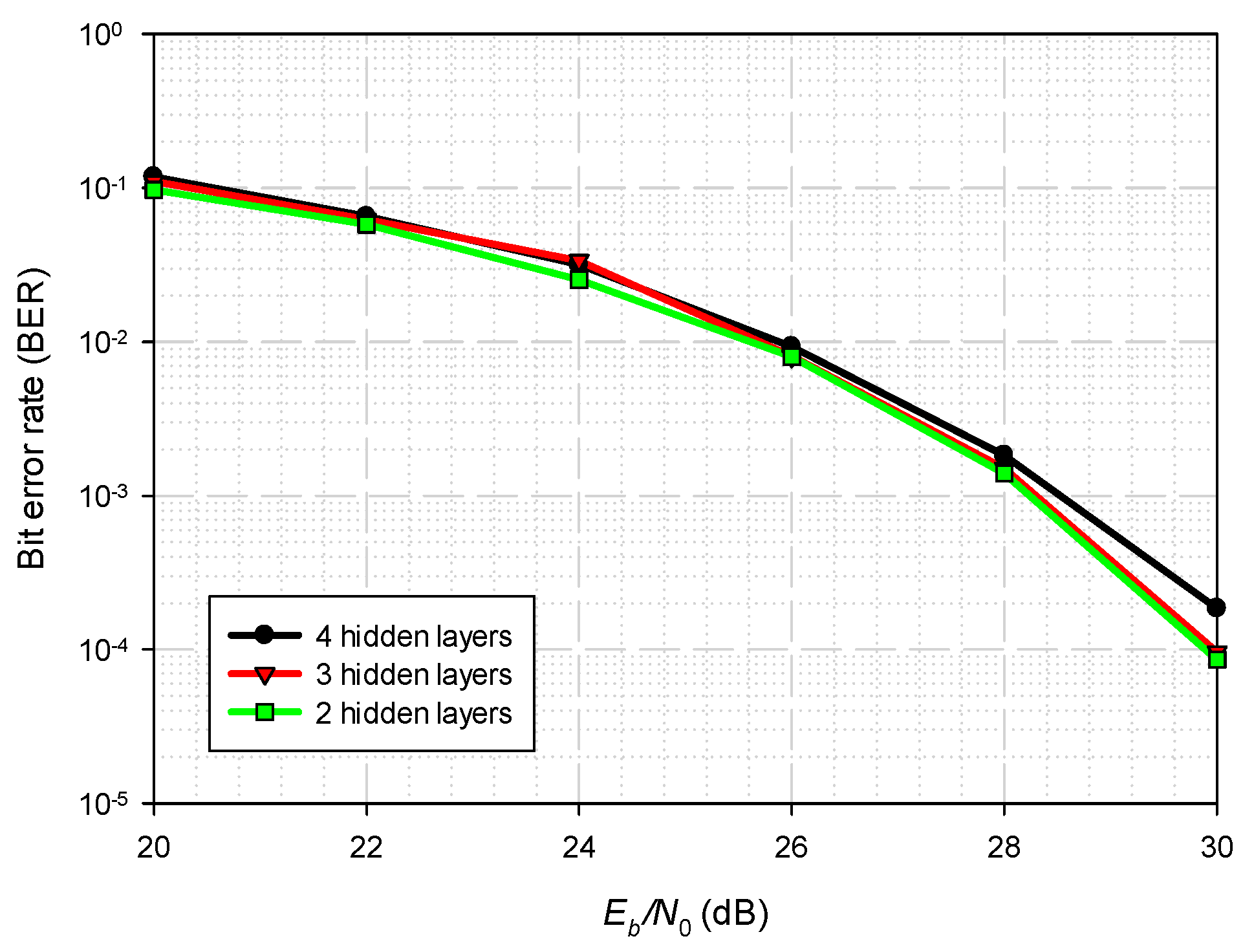
Figure 5, the ANN with a 4-neuron hidden layer achieved the minimum mean-square error. The impacts of increasing the number of hidden layers are shown in
Figure 7 and
Figure 8. Intuitively, the adoption of more layers in an ANN seemed to result in better achievable BER. However, the proposed ANN predistorter did not benefit from an increase in the number of hidden layers. This was mainly because the feedback replica of the original electrical source through PD, used as training set for the ANN, was noisy. The ANN became increasingly complicated with each increase in the number of hidden layers, and thus it could not be well trained using this noisy training set. In addition, the inverse function to the characteristic function of the adopted LED is expected to be simple and monotonic. As such, using more hidden layers might cause the ANN to be particularly sensitive to the noise, rather than the desired signal, resulting in overfitting.
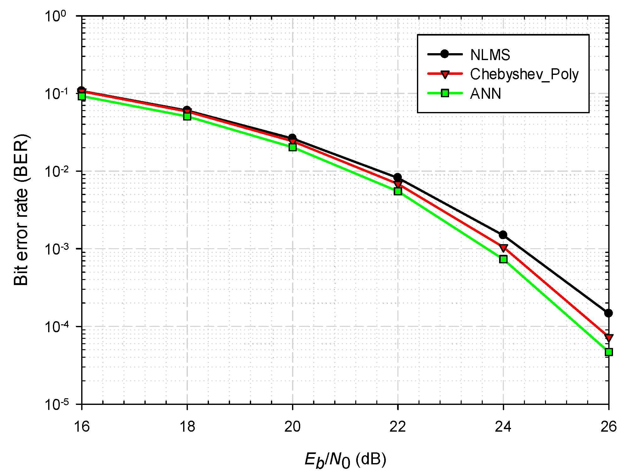
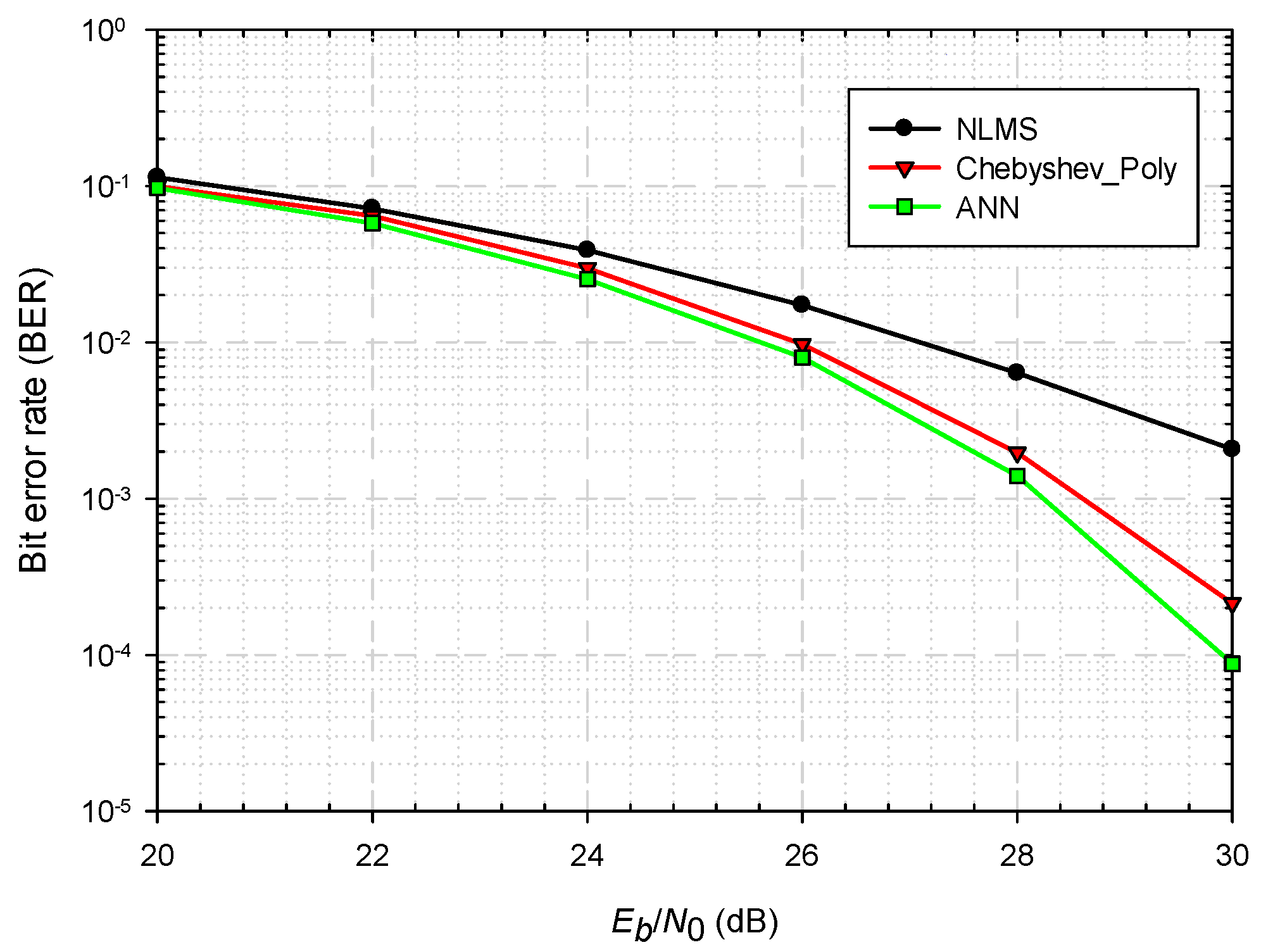
The BERs of several LED predistortion algorithms, including the NLMS [
12], the Chebyshev polynomial [
13], and the proposed ANN predistortion, plotted against the electrical energy per bit to single-sided noise power spectral density
for the cases of 16 QAM (
) and 64 QAM (
) are shown in
Figure 9 and
Figure 10, respectively. In the cases of both 16 QAM and 64 QAM, it was evident that the BERs reached by the proposed ANN predistortion were lower than those reached by using the NLMS and the Chebyshev polynomial. The NLMS had the worst performance since the NLMS only used a one-dimensional LUT to approximate the predistorter function. In contrast, the Chebyshev polynomial method achieved a better performance than the NLMS method because the Chebyshev polynomial method adds polynomial expansion compensation terms onto the predistortion factors stored in the LUT. Meanwhile, the proposed ANN method, using a cascade of nonlinear functions to approximate the nonlinear predistorter function, was capable of revealing the LED nonlinearity and could adaptively learn it through the training set, i.e., through the scaling feedback signal
.
Notably, there were noise components contained in , and this resulted in almost no performance difference among the NLMS, the Chebyshev polynomial, and the proposed ANN predistortion when the system was under a low scenario. In contrast, in the scenario of moderate , the quality of was better, and thus the proposed ANN predistortion was apparently able to manifest its superiority over the NLMS and Chebyshev polynomial methods in that scenario.
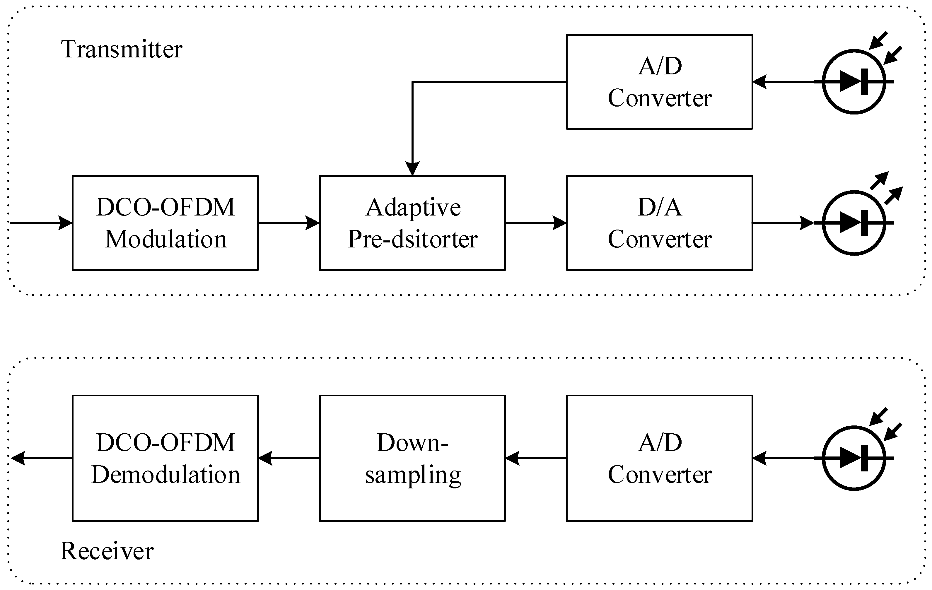
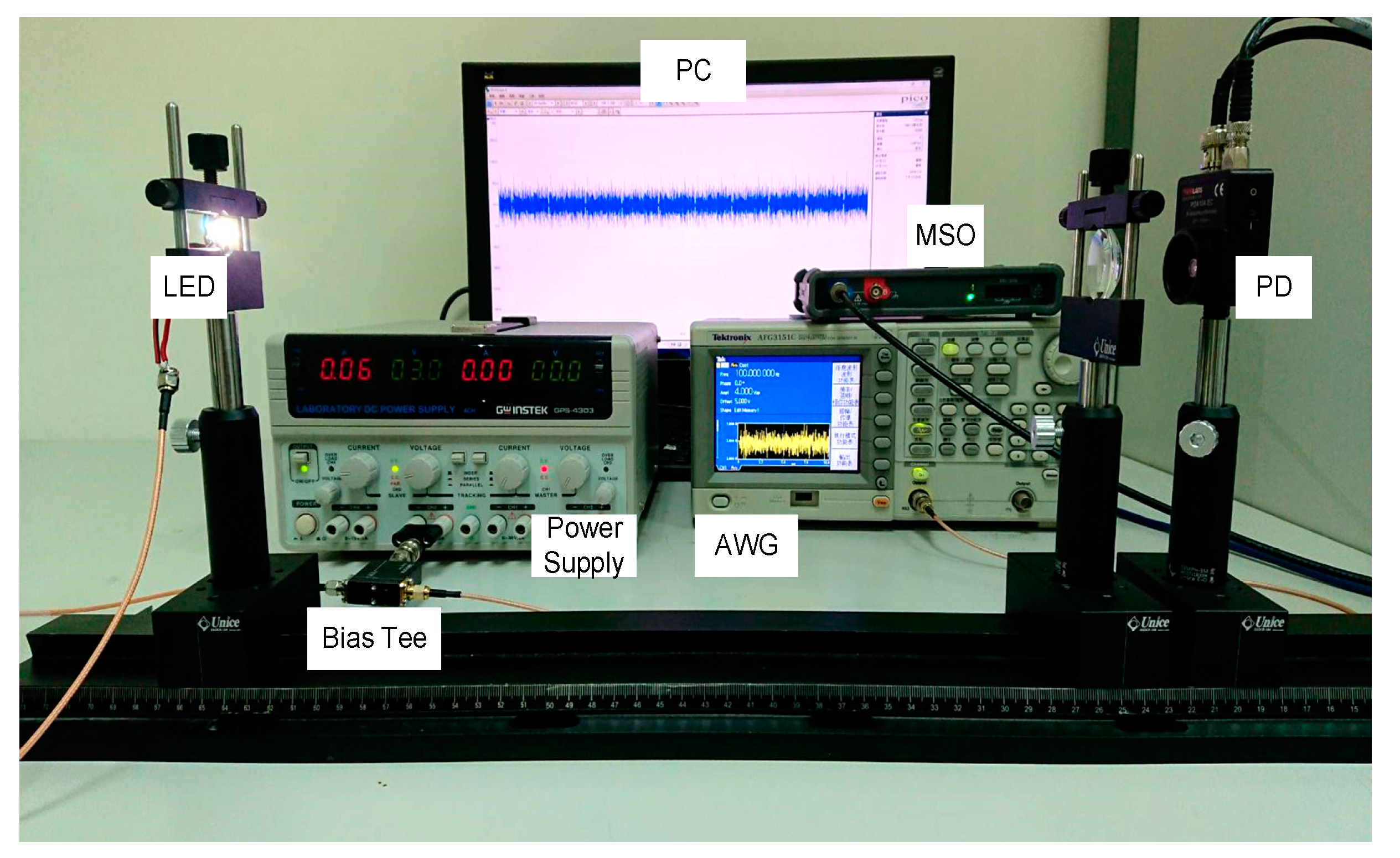
The effectiveness of the ANN predistorter in a DCO-OFDM VLC system was also validated in this study through experimental verification. The system setup of the self-built DCO-OFDM VLC testbed is shown in
Figure 11. A pseudo-random binary sequence was programmed, modulated, and predistorted using the considered predistortion algorithms in the computer. To conduct the D/A conversion, the computer was connected to an arbitrary waveform generator (AWG) (Tektronix AFG3151C) under the constraint of modulation bandwidth of the LED. Through the bias tee (Tektronix PSPL5575A), the generated waveform signal was superimposed onto the bias current to drive the adopted LED (Crescent D01-A1-A33). On the basis of the measured data of the LED in
Table 1, the bias current was set to 60 mA and the mean of the generated waveform signal was set to 5 volts, and these settings caused the operation point of the LED to be 300 mW in order to introduce the nonlinearity effect into the LED emitting optical signal.
A PD (THORLABS PDA10A-EC), with a 150 MHz bandwidth, 1 mm
2 active area, and
V/A transimpedance gain, was utilized to direct detect the light intensity. To conduct the A/D conversion, the PD output was captured by using a mixed signal oscilloscope (MSO) (PicoScope 3205D), and then followed by a process of downsampling. Finally, the sampled signal was further subjected to packet synchronization, demodulation, and BER analysis.
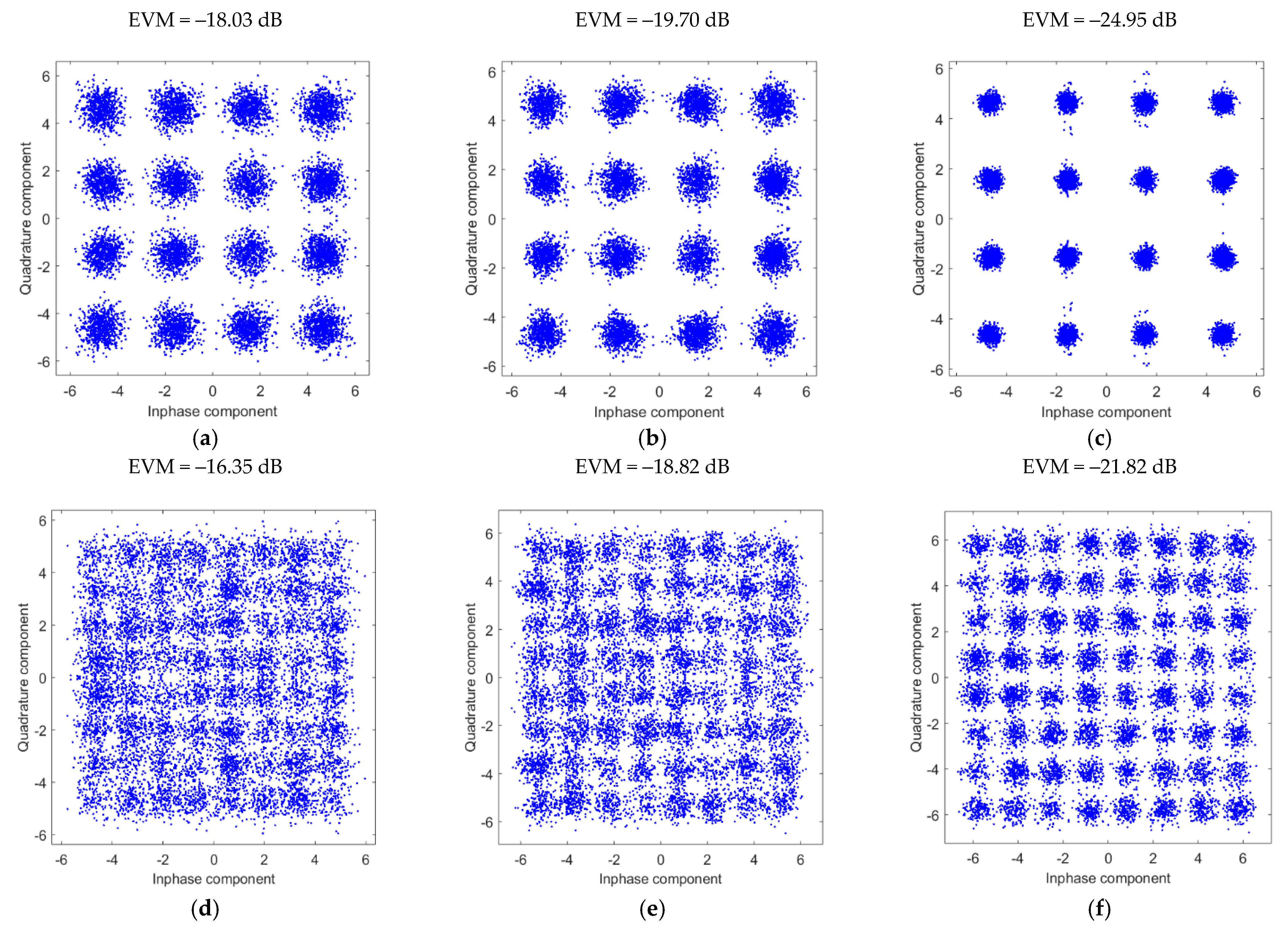
Figure 12 shows constellation diagrams of 16 QAM and 64 QAM modulation under the condition that the distance between the LED and the PD was 40 cm. Obviously, the constellation diagrams with the ANN predistorter are much clearer than those with either the NLMS or Chebyshev polynomial predistorters. This observation was also validated by the error vector magnitude (EVM) results, which are shown in the titles of each subfigure.
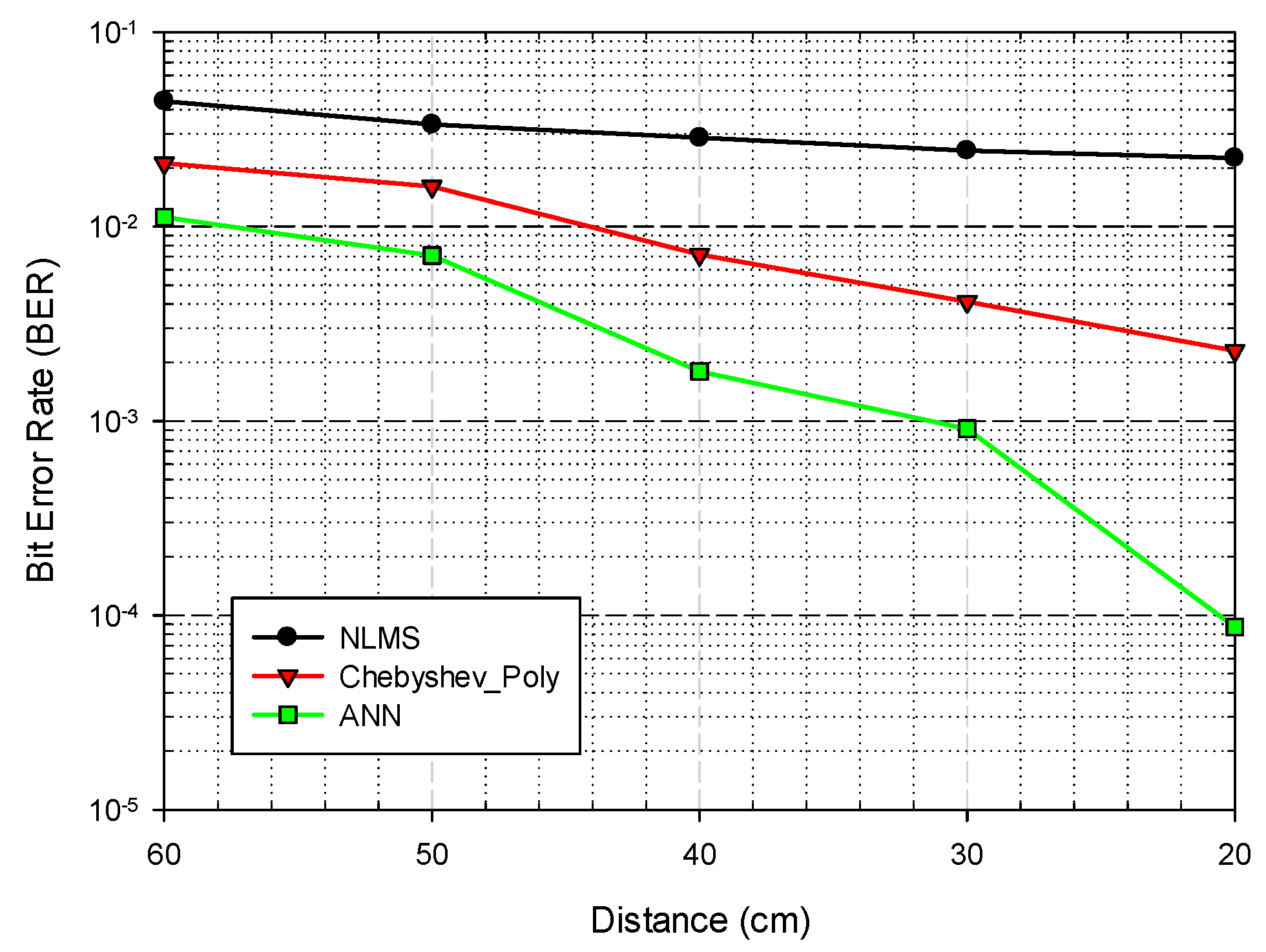
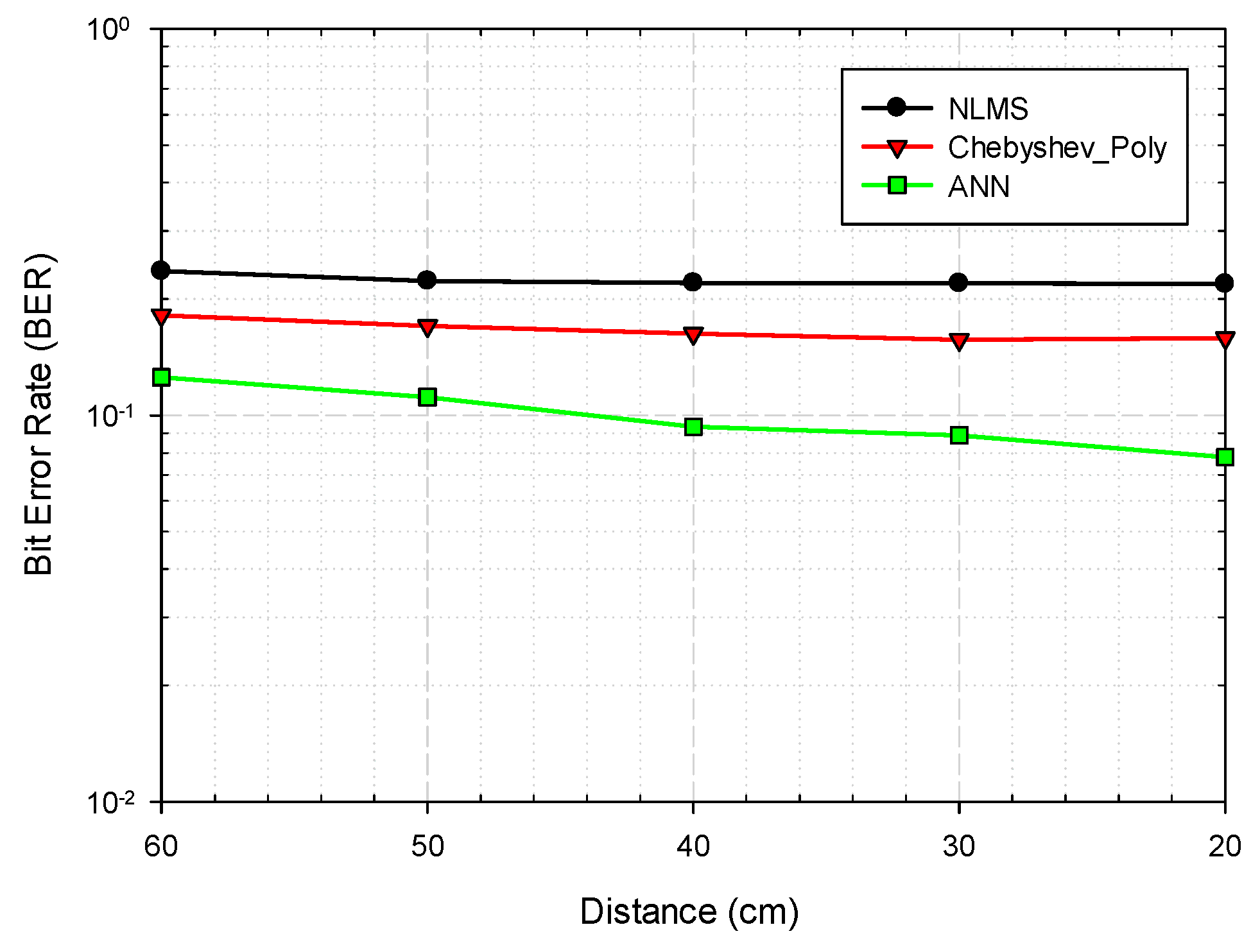
Moreover, the BERs of the considered LED predistortion algorithms plotted against the distances between the LED and the PD for the cases of 16 QAM (
) and 64 QAM (
) are shown in
Figure 13 and
Figure 14, respectively. As can be seen in
Figure 13, the experimental results verified that the BER of the 16 QAM modulated OFDM system with the proposed ANN predistorter was significantly superior to those with the NLMS and the Chebyshev polynomial predistorters. As for the case of the 64 QAM-modulated OFDM signals shown in
Figure 14, the BER of the system with the proposed ANN predistorter still outperformed those with the NLMS and the Chebyshev polynomial predistorters. In summary, the experimental results validated the view that the proposed ANN predistorter was capable of adequately compensating for LED nonlinearity, and hence achieving better system performance compared to the NLMS and the Chebyshev polynomial predistorters.


