1. Introduction
The road map to advanced technologies such as Long Term Evolution (LTE) release 8–14 [
1] and The 5th Generation New Radio (5G-NR) technology [
2] have led to significant breakthroughs. Many studies and researchers have created a scientific basis for engineering challenges and physical problems, such as peak spectral efficiency, fast fading channel response, and destructive effects in a multi-path channel [
3,
4,
5,
6]. Dealing with fading and selective effects, a delay spread, high Doppler effects, fluctuation channels characterized in the time and frequency domains, and random scatters near the User Equipment (UE) or the small-cell are not trivial issues [
4,
5]. In addition, the demands in the real world of next-generation mobile technology for high mobility, low latency, spectrum efficiency, peak data rates, and ultra multi-user experience, with emphasis on multiple users and sharing radio access, are increasing and have expanded the research field. There are a number of threshold conditions that must be met in order to operate multi-user access techniques such as Orthogonal Multiple Access (OMA)/Non-OMA (NOMA) techniques [
7,
8,
9], or Multi-User (MU)- Multiple Input, Multiple Output (MIMO) [
10,
11,
12]. The first condition is the ability to decoding a specific stream transmission, from spatial-multiplexing streams, under a random Signal Interference Noise Ratio (SINR) with random interference signals. The second condition is to combines unlicensed and licensed technology. The meaning of this combination is to manage a significant number of the wireless device under specific macro cell, without sharing any Physical Upload Shared Channel (PUSCH), Without sharing a common scheduler, and also without any Demodulation Reference-Signals (DM-RS), which help to run algorithms for estimating and offsetting interfering, like Minimum Mean Square Error-Interference Rejection Combining (MMSE-IRC) [
13,
14,
15]. For example, the use License Assisted Access (LAA) protocol [
16,
17], or Device-To-Device (DTD) technique [
18], to get a significant channel capacity, in an environment with multi-interferences. Complicated subjects, such as radio management and fairness access, which require peak data in real-time applications, and also emerging applications such as inter-vehicle communication [
19], increase these engineering challenges.
Previous works such as [
20,
21,
22] have expanded this research area. These situations occur, especially in bands below 6 GHz, because spatial selectivity capacity requires instant time or frequency selectivity. The potential risk of exposure of essential international infrastructure in the private market or the military sector to a jammer attack or a multi-interference environment is troublesome.
On the one hand, there is massive investment in information security networks and core layers against cyber attacks. On the other hand, with some simple jammer devices, it is possible to cut off radio links between Internet of Things (IoT) devices inside medical refrigerators in hospitals or to disrupt the communication of GPS location systems [
23]. They can also jam vehicle-to-vehicle communication between autonomous cars [
24] and other critical systems. Military systems are also vulnerable to many jammer techniques, and the cumulative damage can be devastating.
In practice, we must develop and utilize two critical and advanced techniques when designing modern communication systems. First, an MIMO array or a massive MIMO technique is needed [
25,
26]. Second, smart control systems under Channel State Information (CSI) are known to the receiver and transmitter at the same time, streamed through the remote control channel, or the Physical Upload Control Channel (PUCCH). This capability will allow us to configure a system with flexible immunity, which includes a trade-off between handling the jammer and handling the strong interference signals in a multi-interference environment, and in parallel to create a large number of receive paths that are orthogonal to each other. This is needed for independent decoding and to increase the capacity of the channel. The benefits of this agenda are far-reaching. In a situation without any jammer or any interference signals between the transmitter and the receiver, we can achieve improvements over spatial multiplexing (SM) [
27], or eigenvalue beamforming [
27,
28]. The above trade-off is expressed especially under the assumption of dynamic and random channel response or very high mobility of the transmitter relative to the receiver, or vice versa. Assuming a scattering-rich propagation channel or a two-ring model scatter environment [
5] also creates a challenge. Improvements in channel estimation or estimation of the random Direction Of Arrival (DOA) of the receive paths [
29] are also considered to produce improvement in this agenda.
Here, we present the significant effects of a smart jammer and interference on a wireless mobile network’s physical (PHY) layer and in an unlicensed wireless communication environment. An understanding of these effects, without a doubt, will contribute to the modern techniques that we have mentioned. The common base of these phenomena is the destruction of the principle orthogonality region, which we expand in this paper (
Appendix A). Orthogonality between the various receive paths in the surrounding multi-path channels is particularly significant in the MIMO array with multiple receive and transmit antennas [
27]; however, it allows for high vulnerability in MIMO techniques.
By creating orthogonality between the paths, we achieve maximum capacity in the channel [
27]. The ability to receive multiple independent data streams fixes the internecine effects on the channel matrix, achieves a full rank in this matrix, and finds the optimum eigenvalue distribution that leads to a maximum capacity [
27]. The maximum capacity is obtained when the ratio of the maximum eigenvalue to the minimum eigenvalue converges to 1 [
27]. A system with only CSI at the Receiver (CSIR), every channel path has a power gain equal to the eigenvalue of the channel matrix. This is in addition to the fact that the effective transmit power is
times the total transmit power, when
is the number of transmit antennas. The orthogonality between the paths also leads to significant Success Interference Cancellation (SIC) implemented in many decoder techniques, especially in MRRC. In a multi-interfering environment there is damage to the orthogonal spectrum (
Appendix A), and as a result, the performance of the receiver decreases significantly.
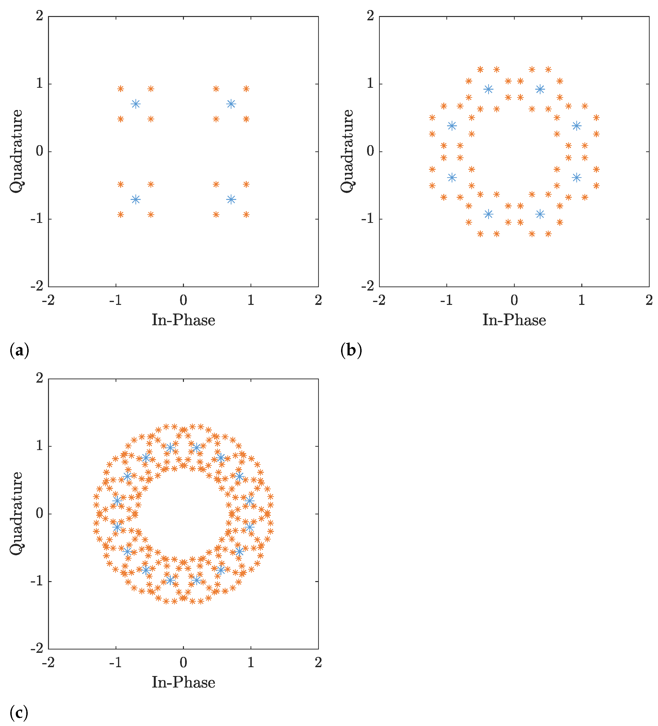
Another significant effect that we present in this paper adds to the orthogonality region’s hit: replicating the interference and information symbols in the MRRC combiner after the interferer is received. This phenomenon is reflected in the constellation receiver, dependent on the Signal Interference Ratio (SIR), and the constellation order. Without a feedback system that fixes those duplicate symbols, this phenomenon will be complicated for advanced decoder capabilities such as Sphere Decoder (SD), Zero Forcings (ZF), and Best Linear Estimation (BLE). These effects intensify under the assumptions we make in this paper.
A clear example of our assumption can be found in the HetNet scenario [
30,
31]. In this case, we assume that we have several small cells and pieces of User Equipment (UE), both equipped with multi-transmission and multi-receiver antennas and communicated with a single macro-cell in the same network environment without sharing the same scheduler. In this case, we assume a full-duplex (FD) mode and Time Division Duplex (TDD) access through a slow-fading channel, and a random DOA receives angle, in addition to Uniform Linear Array (ULA) antennas. This situation [
31] is complicated because the UE, the small cells, and the base-station can play the role of the transmitter, receiver, and interferer at the same time. Another assumption is that the transmitter and the interference’s transmission are transmitted under the Orthogonal Space-Time Block Codes (OSTBC)-Alamouti scheme, also receive Alamouti decoder MRRC combiner with Maximum Likelihood (ML) search. The modulation is a Common Envelope (CE), to save energy and lower the Peak-to-Average Power Ratio (PAPR). Another assumption is that the interference occurs regularly, meaning that the statistical average of the product between the transmitter’s symbols and the symbols of the receiver is different from zero [
32].
In a military communication situation, Partial Band Noise (PBN) jammers [
33], and smart jammers [
21] are present. In these situations, a smart jammer learns and estimates the channel matrix between a legitimate transmission and his receiver. If we have a wide-band noise jammer [
33] or even a PBN jammer [
34], we can use the eigenvalue beamforming technique [
35] and cancel the jammer effects with the null steering that eigenvalue beamforming will create [
27]. In the smart jammer case, we must also control the MIMO array in the transmitter and in the receiver together, meaning also the CSI at the transmitter (CSIT).
In recent years, significantly advanced interference cancellation techniques, such as MMSE–Interference Rejection Combining (MMSE-IRC) and MMSE–Maximal Ratio Combining (MMSE-MRC), have been developed and implemented in advanced LTE [
15,
36,
37]. The next step is the new algorithm interference, and anti-jamming generation is required, especially under the assumption of TDD access and Ultra-Reliable and Low-Latency Communications (URLLC) in 5G requirements. These requirements are a binding reduction in the computing of the co-variance [
36] matrix and the time estimation of the channel, on the transmitter and the receiver sides. In our future works, we will address these requirements in developing fitting algorithms.
The purpose of this paper was to refine the challenge in order to deal with those impacts. We start by understanding the limitations of advanced diversity techniques as the OSTBC-Alamouti scheme, based only on the CSIR, without any closed loop-feedback. This article highlights the lack of re-feeding by focusing on the effects required for correction with the help of a control system. This closed-loop feedback creates and sends feedback that fixes the destructive multi-path and interference effects. In addition, the time response is reduced, and the channel with smart and effective CSIT is learned. These ideas open a window for other researchers. This study presents the impacts of an interferer or a smart jammer synchronizing with UE or with a small cell. Another purpose of this study was to enrich the importance of CSI Interference’s Management (CSI-IM) [
30] at the UE, at the macro base-station, or the small cells, in the same time, similar to the HetNet scenario.
In unlicensed wireless communication, we clarify the importance of CSI-IM in transmissions, in an interferer or smart-jammer environment scenario. We illustrate these effects on the basic principle of MIMO techniques based on an open loop. Another purpose was to show that selective space techniques, such as eigenvalue beamforming and a null spacing matrix that reduces the effects of signal interference, are not enough to deal with highly dynamic interference or smart jammer attacks in the space domain. The main target is to overcome fluctuation channels in the time and frequency domain amid jammer or interferer issues.
Our idea is to create more flexible scheduling in the next 5G-NR transceiver and in new radio access. This paper can be integrated with other papers regarding unique geometric scattering models for MIMO channels [
4,
5]. Some studies work around modern communication with jammers [
15,
21,
31,
36]. This paper and future studies will complement these papers and provide different points of view on this subject. We divide strategies handling multi-interference into two mechanisms. The first is called analog Radio Frequency (RF) interference cancellation, and the second is digital interference cancellation [
30]. We focus here on digital interference received at the combiner process. It is a complicated phenomenon that requires deep research. We must also remain focused on significant targets in 5G-NR, e.g., control model antennas, array beam patterns, and flexible air interfaces, to evaluate the algorithm design’s impact on RF link performance. In addition, we must develop and research mechanisms that create a trade-off between dealing with jammers or strong signal interferences and increasing the channel’s capacity with minimal energy.
The remainder of this paper is organized as follows: in
Section 2, we present the basic principles of diversity transmission using the Alamouti MIMO technique. In
Section 3, we present different interferer techniques: a general interferer, a smart jammer, and a PBN jammer. In
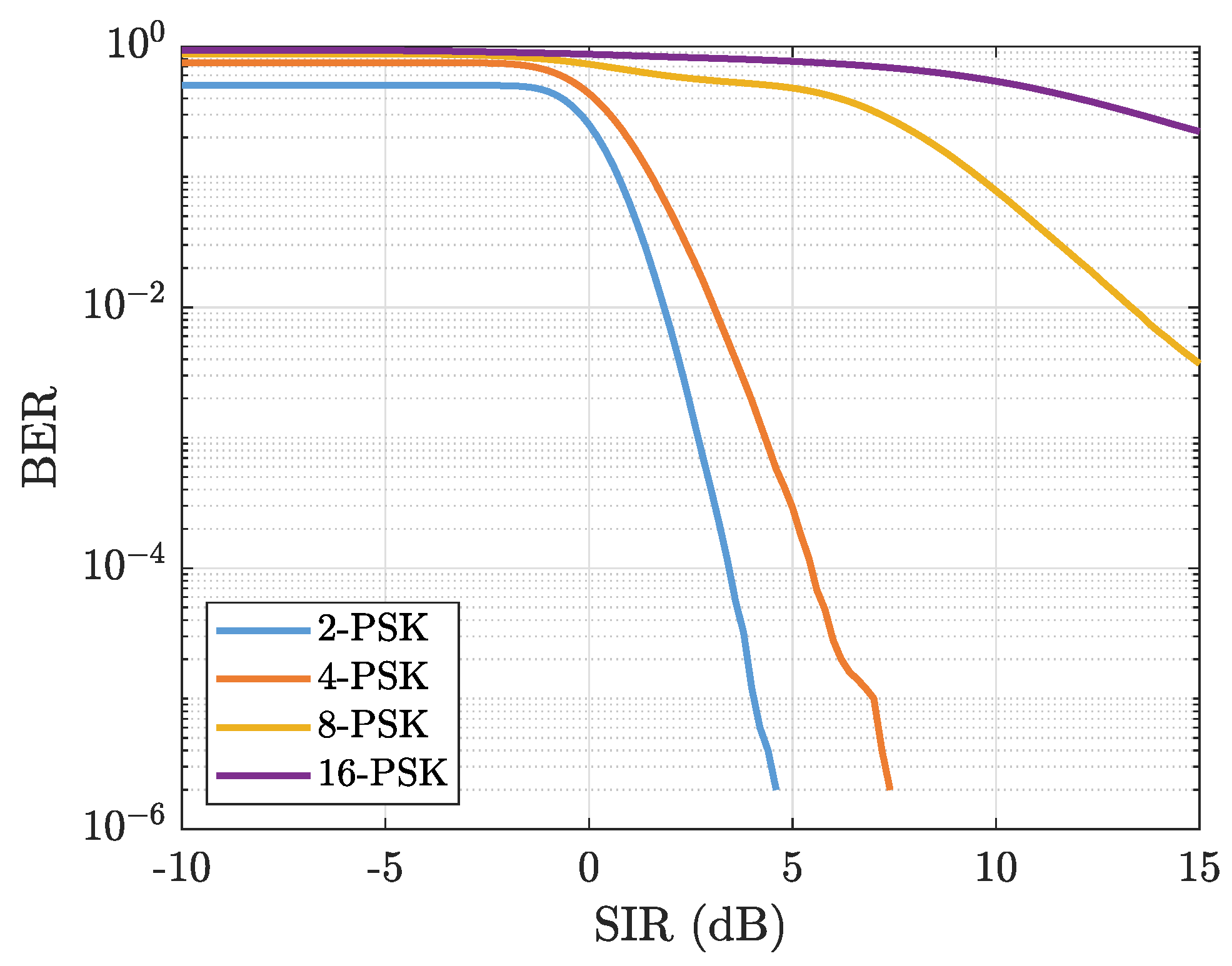
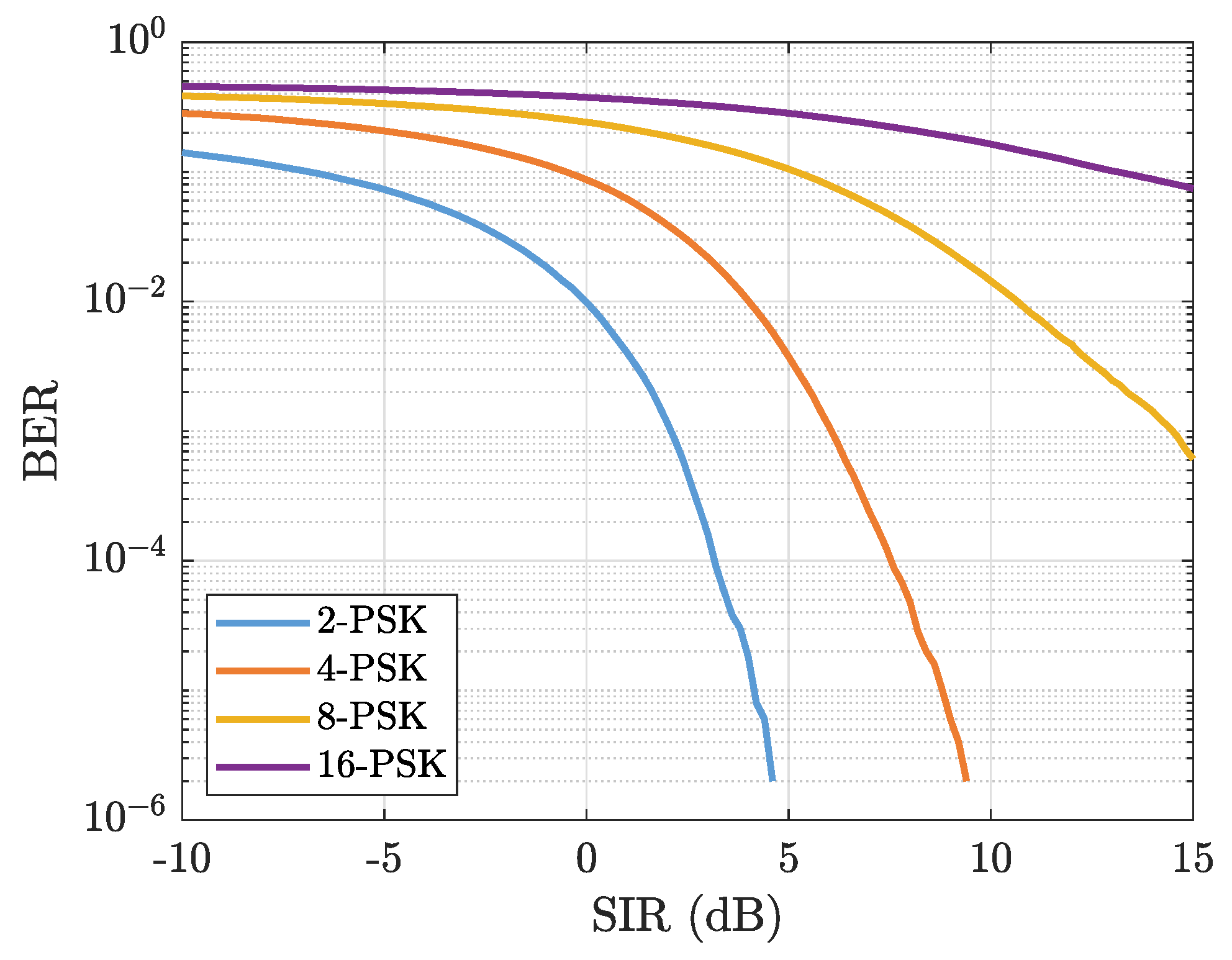
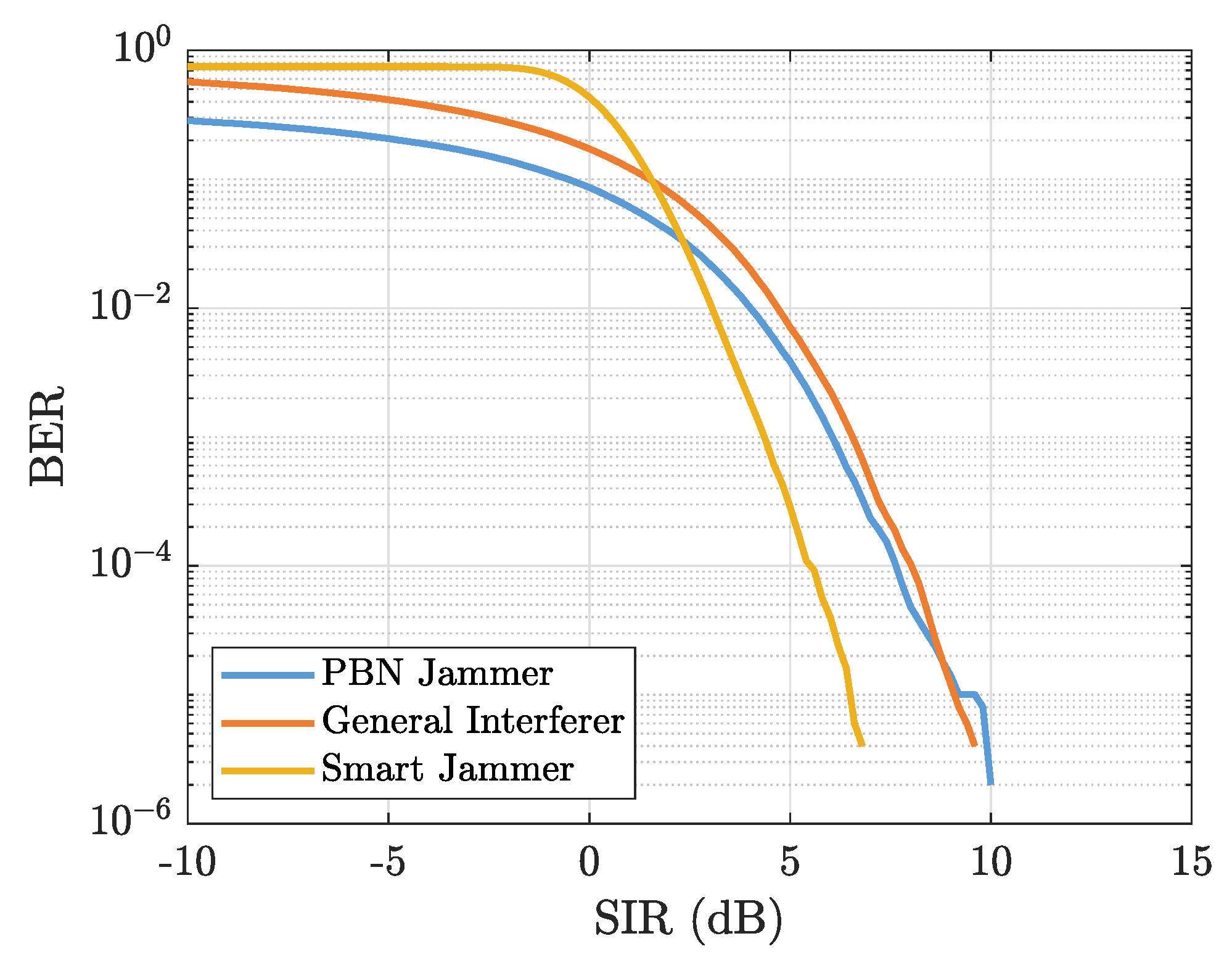
Section 4, we present the simulation results in Bit Error Rate (BER) vs. SIR.
Section 5 summarizes and concludes the paper.
2. Diversity Transmission Using Alamouti MIMO Technique
Transmit diversity can be obtained by Space-Time Coding (STC) that is designed to achieve maximum spatial diversity. One simple space-time code is the Alamouti code, which is used in most MIMO systems today. This method’s significant advantage over other techniques is that it doesn’t require CSIT, which reduces complexity while achieving maximum spatial diversity. We present the effects of interfering with the Alamouti STC. To understand these effects in-depth, we will provide a short brief on the known
Alamouti STC technique [
1].
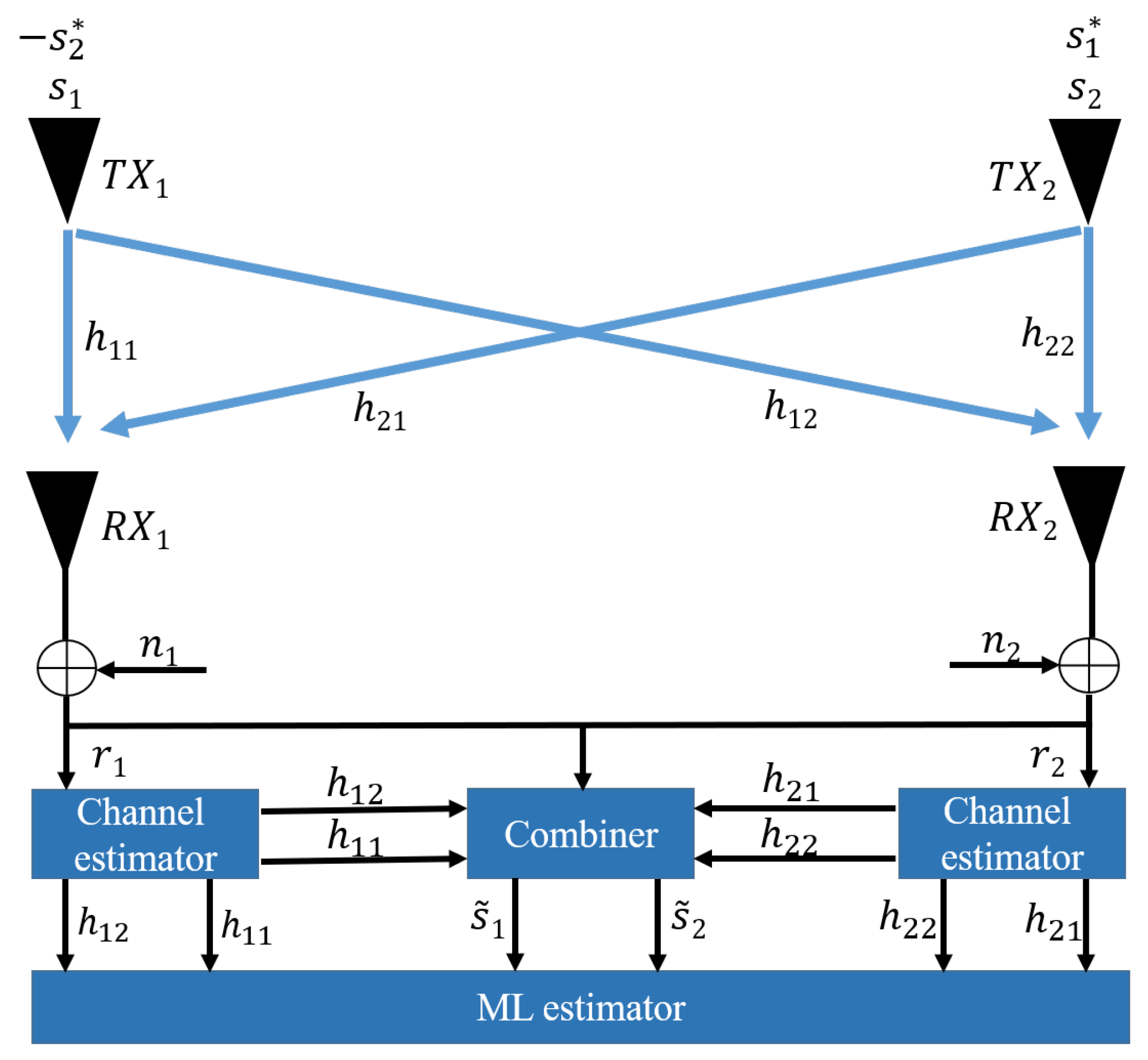
Figure 1 shows a block diagram of the
Alamouti system case. The transmission consists of two transmission antennas,
and
. These antennas transmit in the Alamouti STC technique and represent the UE. Next, the signal transmits through a MIMO channel model with four flat fading paths independent and uncorrelated assume. These four paths are represented by complex channel gains
,
,
,
. The indexes are the indexes of
and
antennas, respectively, as shown in
Table 1 [
1,
27]. The receive block includes two receive antennas,
and
, and an Alamouti space-time decoder combined with MRRC or diversity combining channel state estimation with ML decoding. This receive block is subject to the rules of the base-station (NodeB).
The Alamouti STC operation of the two symbols
and
is defined in
Table 2 and includes two transmit antennas under two-time slots. At some time
t, symbols
and
are transmitted from
and
, respectively. At time
, where
is the symbol duration, the symbols
and
are transmitted from
and
, respectively [
1]. The operator
represents the complex conjugate.
The received signal
r and Additive White Gaussian Noise (AWGN) signal
n are denoted by two indexes,
and
, where
denotes the number of received antennas, and
denotes the received signal at time
t or
, respectively. In
Table 3, for example,
denotes the received signal at time
t at
.
Figure 1 implies that the receiver equations can be described as [
1,
27]
The combining rules for a
Alamouti system case are here defined as [
1,
27]
Substituting (
1) into (
2) yields [
27]
and
The estimation of each symbol
and
is multiplied with the norm of each complex channel gain without the other symbol’s presence. Finally, the last receive step is the ML estimate. The transmitted symbol is estimated as follows [
27]:
Another way to display Equation (
1) is through matrices. After mathematical operations of conjugation, the model will be [
1,
27]
In short,
where
is the receiver signal vector,
is the symbol matrix,
is the AWGN noise vector, and
is the channel matrix between the transmitter and the receiver, shown as
An important feature of this Alamouti coding matrix is the orthogonality between its columns [
27]. If the condition
is met, the vectors are orthogonal. The operator
is the complex transpose. For the
case,
This critical feature allows the symbols to be decoded and Equation (3) to be obtained. It can also be seen by presenting Equation (
2) as the following matrix:
Next, (6) is substituted into the above equation to obtain
which is the same as Equation (3).
denotes an identity matrix of size 2.
In the next section, we will present the impairment of this orthogonality through interference’s.
3. Alamouti MIMO Link in the Presence of Different Interferer Techniques
This section discusses three types of jammer strategies or interference that could be present in a certain space. Those classifications are a general interferer, a smart jammer, and a contiguous PBN jammer. We assume that the general interferer and the smart jammer have a slow-fading channel, are located in the same environment, are using OSTBC transmissions with
MIMO array, and transmits a CE with FD assume and TDD access. In addition, they have a different scheduler, i.e., a HetNet scenario [
2,
30].
We will discuss the interference effects on the receive symbols. Each jammer or interference technique has a different impact on the target communication system, so different Anti-Jamming (AJ) methods to cancel the jammer effects are needed. It is essential to examine the specific target’s effects, especially in the mathematical design, BER, the constellation diagram, and SIR measurements. This is significant because if the same advanced cancellation technique, such as RF analog cancellation or beamforming with null-space-like spatial multiplexing [
27], or interference rejection combining (IRC) algorithm [
13,
36] are not effective, jammer or interference symbols are received.
The issues of interference management in the Radio Access Network (RAN) and Radio Link Control (RLC), to optimize the power and spectral efficiency, are critical, especially in 5G-NR access. We have a new problem in the demodulation and the decoder process called digital interference cancellation. Comparing the different jammers is necessary because we want to model and distinguish between the different effects in BER and SIR execution.
It is essential to emphasize the effects of orthogonality violation in the spectrum, which results from the multiplicity of interferences between the transmitter and the receiver. Space-time coding is used to achieve spatial diversity. It is possible because of the underlying propagation physics in a multi-path communication channel [
27]. That is, every pair path transmits between the transmission to the receiver is sufficiently uncorrelated. In
Appendix A, we analyze mathematically and illustrate the significant impairment in the orthogonal spectrum assumption.
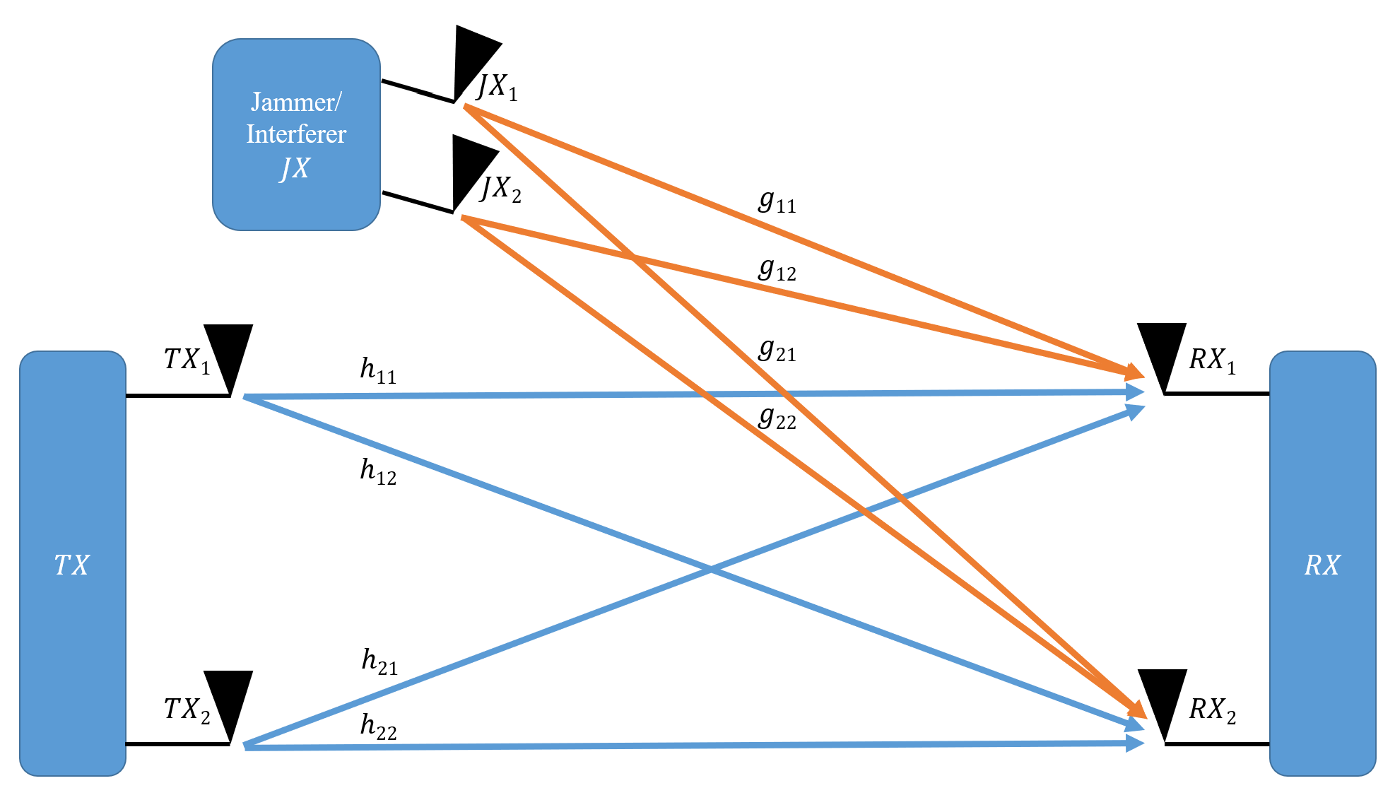
We present a system consisting of a
Alamouti STC transmitter,
, a receiver,
, as described in the previous section, and an interferer transmitter,
, as illustrated in
Figure 2. We assume a far-field between the receiver and the transmitter and interference [
4,
5].
In a general case where several neighboring interferences are present in the space, the received signal vector
is
assuming the signal’s transmission power is equal to
P, where
L is the number of interferences. When considering a single dominant interference, i.e., a very high Dominant Interferer Proportion (DIP) ratio [
38] the received signal vector
becomes
We presented expressions
and
in the previous section. SIR and SNR are the signal to interference and the signal to noise power ratios, respectively, at the receiver site. We will now discuss the expression
. Like the signal, the jammer consists of two transmission antennas,
and
. The jammer transmits through a MIMO channel model with four flat fading paths assumed to be independent and uncorrelated. These four paths are represented by complex channel gains
,
,
, and
. The indexes are the indexes of
and
antennas, respectively, as shown in
Table 4.
The next subsection presents three representative and essential examples of interference and jammer techniques: a general interferer, a smart jammer, and a PBN jammer.
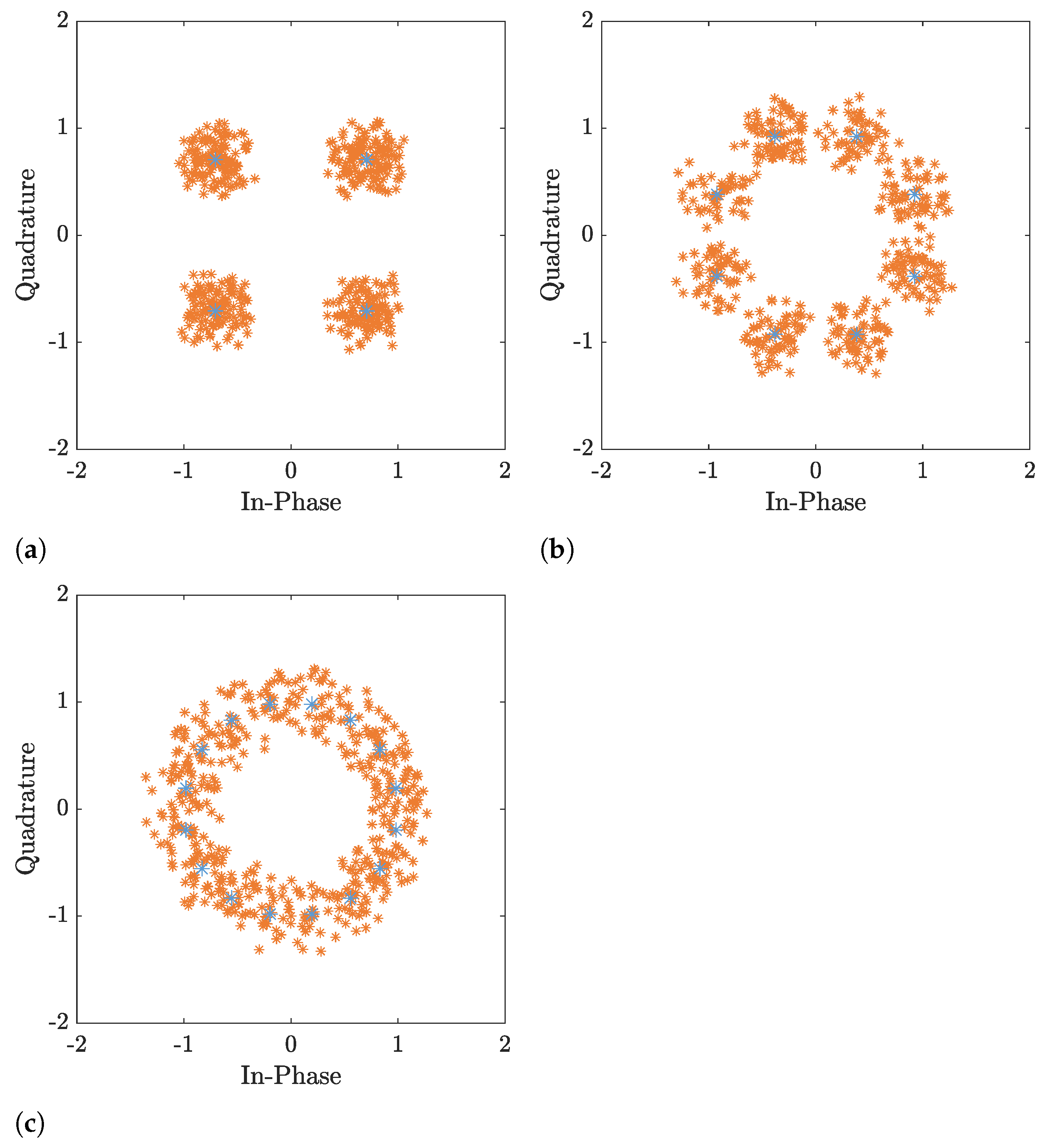
3.1. General Interferer
As mentioned above, the rapid rise in the need to connect thousands of wireless mobile components in a specific area is binding to improve the spectral efficiency per unit area, especially in frequency bands below 6 GHz. To achieve those high requirements, the deployment of many small cells per area is necessary [
30,
31,
39].
The mobile or modern wireless architecture has a wide range of manufacturers under license and unlicensed standards. Multiple manufacturers that communicate with UE pieces in the same local network area without sharing synchronization in the radio management or without common schedulers create serious and complicated problems. Problems include Inter-Cell Interference (ICI) [
40] and Cross-Link Interference (CLI) between neighboring small cells of different directional transmissions [
31]. These situations require a state of continuous decoding ability when a strong interference signal power is present, or under minimum SINR conditions [
37]. A prevention situation that creates severe chain reactions such as rolling modulation and multiple handovers to far cells is also considered. False decoding of the packet detection in the front receiver process also creates a complicated situation. Even systems with a Frequency-Hoping Spread Spectrum (FHSS) scheme and a Direct Sequence Spread Spectrum (DSSS), which are embedded in protocols and standards such as Wireless Local Area Networks (WLANs), Bluetooth, and Wireless Personal Area Network (WPANs), create a situation of mutual interference and receive strong interference signals one from the other [
41].
The most realistic and complicated situations are the HetNet scenario and the multi-Access Point (AP), and the multi-user scenario. These scenarios are common in 5G-NR under the dynamic TDD assumption, which produces dynamic switch point between uplinks/downlinks [
42]. These scenarios create three complicated issues. The first is that every component, user, small cell, and macrocell base-station, can play the rule of interfering, transmit, and receiving simultaneously. The second involves the complexity of un-decode-ability in the presence of strong interference signals [
37], much more so than the SIR threshold to achieve a discovery production threshold. Third, distinguishing between data symbols and interference symbols when combining multi-interference signals with different power levels that are out of synchronization with discovery times [
32], or hidden beyond a powerful interference signal, is also very challenging.
This subsection describes a general interferer’s specific case based on these scenarios, combined with the Alamouti-STC scheme. The mathematics analysis in the frequency domain contributes to a critical study that describes the impact of synchronization errors on Alamouti-STC-based cooperative MIMO schemes [
32]. In this analysis, we describe UE transmitting an Alamouti-STC scheme, with the same assumptions made at the beginning of this section, to other UEs that act as a general interferer or a general jammer device. That jammer or interferer also transmits the Alamouti-STC. The interferer symbols
and
are defined in
Table 5.
We therefore can write Equation (10) as
The receiver equations are
Substituting (12) into the combining Equation (
2) yields
and
It can be seen that, compared to Equation (3), we received, in addition to the symbols, expressions containing combinations of the interferer with the channel components. As a result, errors in detecting the symbols and a decrease in performance will be obtained. In
Section 4, we will present simulation results for representative cases of this phenomenon.
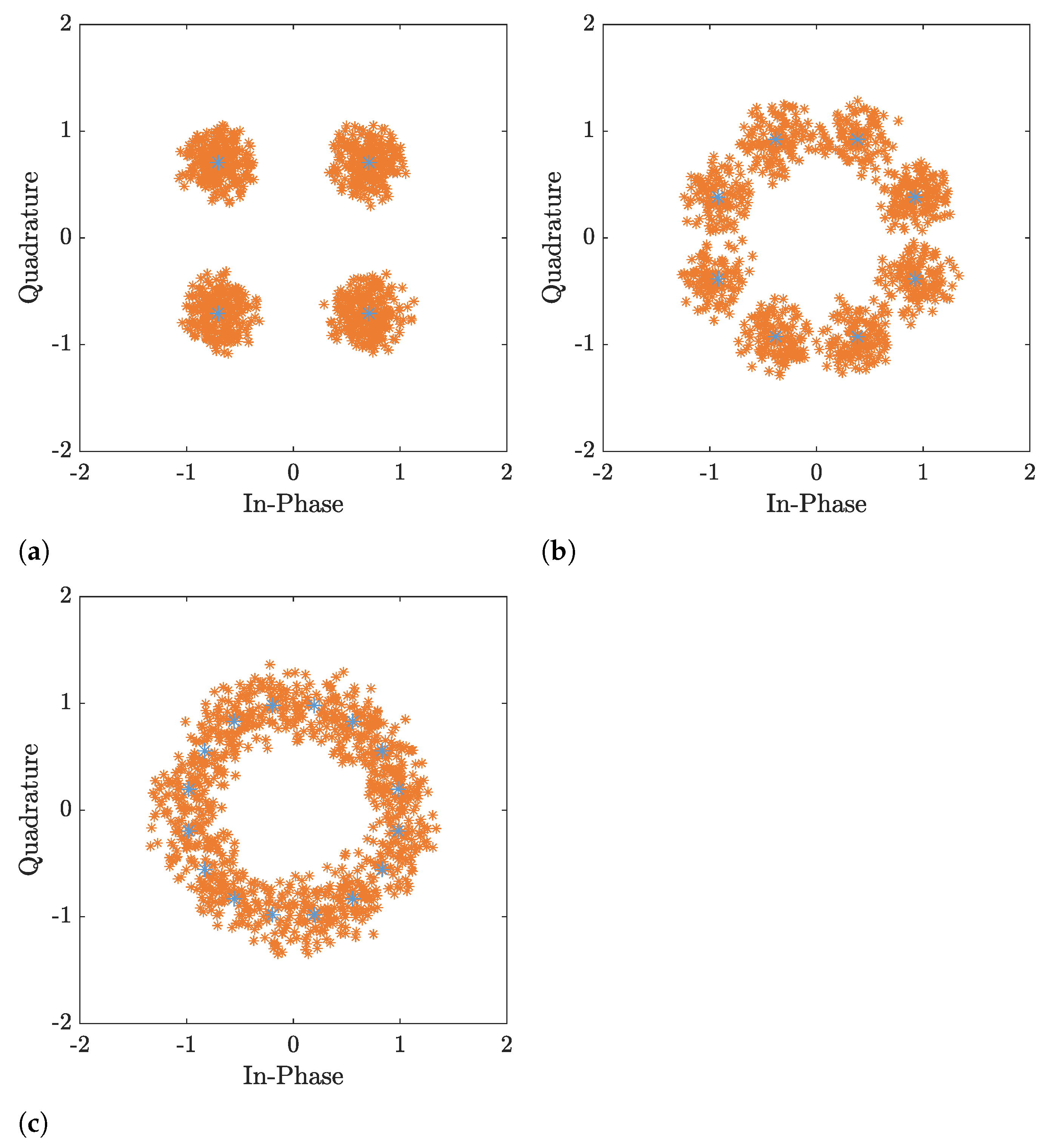
3.2. Smart Jammer
When we describe the smart jammer principle, it is critical to know the RAN behavior and the protocols that manage the PHY layer of the target wireless communication system’s air interface. A smart jammer has two main guiding principles. The first one is the ability to estimate the channel matrix or the CSI between the UE to the base-station (e/gNodeB), and between the jammer to this base-station (NodeB), from the jammer’s perspective [
21]. An example is a smart jammer technique called a pilot-nulling attack. The adaptive process is called Battle Damage Assessment (BDA) [
43]. Another example is a jammer that joins a network to legitimize the UE and manipulate the RF PHY layer. This is very destructive and effective against the communication system. The second principle is communication deterioration by converting the target system’s advantage to the most significant disadvantage [
27]. An excellent example of this scenario is the exploitation of the channel’s multiplicity of paths that characterizes Rayleigh fading. This exploitation is manifested in the fact that, with advanced MIMO techniques, we cause in the receiver processing a situation of linear independence between every path [
27]. If the smart jammer hits this principle, many interference signals will be involved in the de-modulator and the combiner at the receive side. It leads to a destructive chain reaction that begins with a decrease in the modulation order that extends the transmission time and causes a decrease in BER performance.
In this subsection, we describe the communication model of combining a smart jammer using the Alamouti-STC MIMO model, which is a
MIMO array. Based on the assumption that the smart jammer is estimating the channel matrix,
, between the UE to the base-station (NodeB), we can write Equation (11) as
After normalizing the powers, the receive equations are
If we are substituting (15) into the combiner rule at the receiver (
2), it yields
and
The result obtained is impressive because the interference, multiplied by the norms, was obtained in addition to the symbol, i.e., the interfering symbol was added. In
Section 4, we will present simulation results for representative cases of this phenomenon.
3.3. Partial Band Noise Jammer
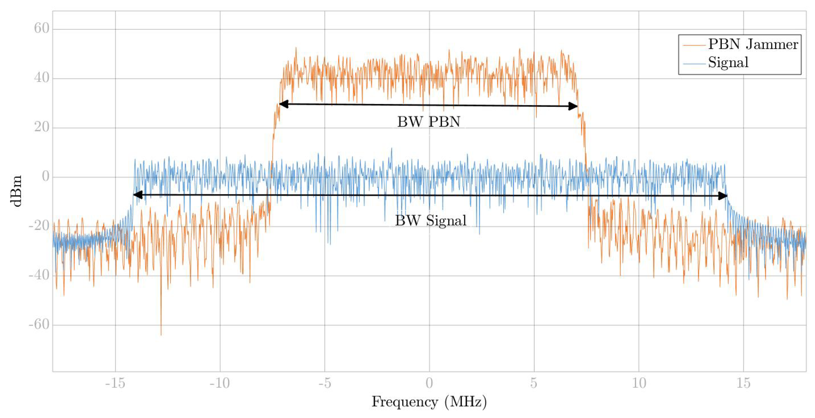
The PBN jammer [
44] places noise jammer energy across a specific portion of the entire system’s target bandwidth. For example,
Figure 3 shows a 50% PBN jammer, i.e., 50% of the target bandwidth noise is added. PBN is a straightforward jammer technique in the modern communication world. PBN does not require any computational estimation or channel estimation between the target from the jammer’s perspective and the receiver or any knowledge about the time synchronization of the target’s preamble packet.
The influence of the PBN jammer on the receiver in the space domain can be negligible if we use MIMO techniques such as Spatial Multiplexing (SM) decoding technique’s, Minimum Variance Distortion-less Response (MVDR), and dynamic beamforming, especially if the channel state information is known to the UE side [
27]. The selectivity of the PBN in the space domain depends on the PBN variance and bandwidth and on the signal noise power. In order to reduce the effect of the PBN jammer, advanced MIMO techniques at the space domain can be used [
27,
28].
5. Conclusions
In this paper, we study and present the significant impact and performances of the Alamouti scheme in the presence of interferences signals. We assume that the channel is under Rayleigh slow fading, with CE modulation transmission. Understanding the effects of interference in the space-frequency domain is critical for developing a solution to cancel the interference by digital, analog, or antenna separation.
We proved mathematically (
Appendix A), and with a simulation platform, the MIMO-system based on the STC scheme performances in an interference environment decreases. When the CSI is only on the receiver side, it has destructive effects on the receiving and the decoding processes. We showed the violation of the principle of orthogonality that OSTBC produces, by creating uncorrelated channel paths and receiving every path with each antenna, independently. This is a significant issue in a multi-path scenario or urban environment because if all paths received are orthogonal to each other, a full rank in the channel matrix is obtained. Full rank leads to a maximum capacity in the channel, achieved by the sum of constant eigenvalues. The examination of the general interference, the smart jammer, and the PBN jammer showed an impact on the orthogonality region and caused the addition and duplication of received symbols. These phenomena are independent of the DOA, i.e., the transmitter, receiver, and interferer orientation, under a ULA assume.
We showed the BER performances in relation to the SIR in the presence of interference. We showed that it is unable to reduce the BER performances for the smart jammer case unless the SIR value is above 0 dB. To overcome this, we must ensure that the CSI will be on the transmission side, and we need to make sure that the CSI will be on both sides at the same time.
We chose to focus on the simple case with a single dominant interferer because already, in this case, we prove mathematically and with simulations performances impairments that justify identification, control and feedback. When dealing with complex problems such as multi-interference, as occurs in reality, it is necessary to simplify the problem, build models, and then deal with the complex problems.
Our subsequent studies will aim to reach a breakthrough that enables the creation of fast, smart, and learning feedback. This feedback will be performed using an algorithm that learns the channels’ characteristics between the transmitter and the interference’s to the receiver, very fast and computes smart feedback between the receiver to the transmitter. This feedback must consider the trade-off between the ability to reduce and the ability to optimize energy-efficient power transmissions in the transmitter, and thus solve the classic full rank optimization problem of the interference cancellation in the receiver.
We must research and develop models and algorithms that can design dynamic-selective channels while executing control processes, decoding SM techniques, cancellation multi-interference’s signals, and can produce corrections in a unique geometric array of antennas. This solution is needed in a system with TDD techniques and an FD system, especially in HetNets sub 6 GHz, such as 5G-NR small cells under a multi-interference environment or military systems that suffer from smart jammers. In the future, we want to fix these problems, in addition to selective-fast-fading channels, and multi-interference with high-order modulation.


