
Project-Based Learning and Evaluation in an Online Digital Design Course


1
Information Systems and Processing Group, Institute of Electronics and Informatics Engineering of Aveiro (IEETA), University of Aveiro, 3810-193 Aveiro, Portugal
2
Department of Electronics, Telecommunications and Informatics, University of Aveiro, 3810-193 Aveiro, Portugal
Electronics 2021, 10(6), 646; https://doi.org/10.3390/electronics10060646
Submission received: 25 January 2021
/
Revised: 24 February 2021
/
Accepted: 8 March 2021
/
Published: 11 March 2021
(This article belongs to the Special Issue Reconfigurable Digital Systems: Development and Applications)
Abstract
:This paper reports an experience of an abrupt shift from traditional teaching to distance learning within a course on digital system design using programmable logic platforms. The course organization and evaluation model had to be modified on the fly due to the COVID-19 pandemic. The adopted teaching and assessment methodology puts a strong focus on the laboratory component, assigning a very significant weight to project-based evaluation. As the access to laboratory equipment was cut, all the previously accumulated experience had to be modified and adapted to new circumstances. The paper discusses teaching methods employed within the course and analyzes in detail a project-based evaluation accentuated on modeling of a simplified processor. The advantages and drawbacks of the reported teaching methods are appointed. Possible design extensions are also suggested, which permit assigning the same core project to different students. We believe that the proposed project is a valuable instructional tool, in particular, for remote learning/assessment.
1. Introduction
Digital design is a fundamental course in typical computing curricula. The experience acquired in the analysis and design of digital systems can be applied in a very large number of potential domains and is essential for more advanced courses such as computer architecture, digital electronics, and embedded systems. The importance of digital design fully justifies the inclusion of at least one knowledge unit with this thematic in the curricular plans of engineering courses, in the areas of both electronics and computers. The IEEE/ACM Joint Task Force on Computer Engineering Curricula, in its most recent guidelines on Computer Engineering (CE) and Computer Science (CS) curricula, makes clear the need to include topics on digital systems in these curricula [1,2]. The respective latest draft report of Computing Curricula 2020 [3] also identifies digital design as one of knowledge areas in hardware category essential for CE and CS curricula.
In our university, training in the area of digital design for CE curriculum is logically divided between three disciplines: Introduction to Digital Systems, Digital Design Laboratory, and Reconfigurable Computing. The first discipline, Introduction to Digital Systems (IDS), is taught in the first semester of the first year. This is a traditional introductory course on digital design, which covers all of the recommended for undergraduate degree programs in Computer Engineering knowledge units [1,3], such as:
- digital design basics: number representation, codes, arithmetic operations, Boolean algebra;
- basic combinatorial and sequential building blocks (decoders, encoders, multiplexers, adders, barrel shifters, combinatorial multipliers, latches, flip-flops, registers, shift registers, counters);
- digital circuit modeling and simulation on the example of Intel’s Quartus Prime design software [4] (only schematic modeling and behavioral simulation);
- analysis and design of finite state machines;
- design of digital systems of small complexity composed of datapaths and control units using basic combinational and sequential building blocks;
- analysis and design of digital systems including design space exploration, and trade-offs based on constraints such as performance and cost.
The second discipline, Digital Design Laboratory (DDL), logically continues the previous course and is taught in the second semester of the first year of CE curriculum. The aim of this course is to further develop knowledge acquired within IDS with focus on design automation and programmable logic devices and to cover the following topics:
- introduction to architecture of modern programmable devices, such as field-programmable gate arrays (FPGA);
- detailed study of a hardware description language on the example of VHDL, with special emphasis on synthesis-oriented coding styles;
- familiarization with the typical FPGA-based design flow, simulation tools, and methods for system verification;
- synthesis, implementation, and prototyping of digital systems in high capacity programmable logic devices;
- debugging and testing based on the development and educational board DE2-115 [5] with several types of peripherals and interfaces.
The competences acquired in this course allow future engineers to design (from specification to prototype and test) any digital system, based on hardware description languages, schematic capture tools, high capacity programmable logic devices (FPGAs), and respective design tools. The concepts discussed and the competences acquired in DDL are fundamental for other courses of the same or related scientific areas, which address topics in the fields of computer architecture, embedded systems, reconfigurable computing, systems-on-chip, hardware-software co-design, and communication systems.
Finally, the third discipline, Reconfigurable Computing (RC), is taught in the second semester of the fourth year of CE curriculum. This is an advanced course covering programmable systems-on-chip (such as Zynq-7000 of Xilinx [6]), software/hardware co-design, software techniques for embedded applications, and advanced interfaces. This course continues to explore VHDL but studies alternative design flows, tools, and prototyping devices.
Our university has a long tradition in teaching reconfigurable digital design based on FPGAs and Programmable Systems-on-Chip (PSoC) [7,8,9,10,11,12]. Modern FPGA and PSoC devices contain traditional reconfigurable logic enhanced with numerous embedded components, such as multi-core processors, graphics processing units, digital signal processing slices, memories, transceivers, etc. Consequently, FPGA and PSoC enable highly parallel fast hardware to be designed much like software because the desired functions and interconnections are implemented through reconfiguration (by uploading a configuration file to the relevant microchip). Thus, students are capable to design, implement, and test complex systems in a classroom that is not equipped with expensive devices [7].
All the discussed obligatory disciplines involve very strong laboratory experience. In this paper, we discuss teaching methods that have been employed within a Digital Design Laboratory course during the pandemic lockdown and analyze in detail a project evaluation experience. The remainder of this paper is organized as follows: overview of the related work in project-based learning and limitations of previous project-based evaluations are reported in Section 2. The detailed description of the new project proposal is done in Section 3. The evaluation process is described, and the results are discussed in Section 4. Conclusions are given in Section 5.
2. Project-Based Learning
The Digital Design Laboratory (DDL) course aims at developing adequate skills in students to design digital systems using modern languages, tools, and technologies. After the course is completed, the students are expected to have the following capabilities:
- Digital systems modeling based on schematic capture, hardware description languages, and an effective use of synthesis-oriented coding styles.
- Development and prototyping of digital systems based on high-capacity programmable logic devices, such as Field-Programmable Gate Arrays (FPGAs).
- Use of computer-aided design tools for the purposes of modeling, simulation, synthesis, implementation, debugging, testing, and optimization.
DDL is a course in which students apply in a laboratory environment and with real problems, the knowledge and competences acquired in IDS and become familiar with the modeling languages, tools, and digital systems design flows currently employed in industry. In theoretical and laboratory classes, the following topics are covered, using introductory examples, case studies, practical guides, and projects:
- Introduction to FPGAs, design tools, and development kits.
- Modeling in VHDL, simulation and implementation of combinatorial components, arithmetic circuits, elementary sequential circuits, registers and combinatorial shift modules, single port and multi-port memories, and finite state machines.
- Construction and use of testbenches.
- Circuit debugging.
- Fundamental design precautions, namely: reset, synchronization, generation and distribution of clock signals and timing constraints.
DDL provides means and recurs to teaching methods that promote active learning, “know-how”, students’ autonomy, and facilitate the application of skills in various areas of engineering. DDL is a course with a strong practical component and includes one hour of theoretical classes and three hours of labs per week (a semester has around 15 weeks). The theoretical classes are used essentially for the presentation of concepts, examples, and tools that will be employed in the laboratory classes. Practical classes take place in a computer lab with design tools and FPGA-based development kits (one kit for a pair of students). Each lab proposes a set of low to medium complexity practical problems whose solution must be validated and refined experimentally. A limited number of development kits are also available for students’ use outside of class hours.
The teaching and assessment methodology puts a strong focus on the laboratory component, by assigning a significant weight (over 50%) in the calculation of the final grade to projects. This means that, for evaluation purposes, besides of a traditional written exam, which assesses theoretical aspects of the covered topics, two projects are proposed to students. The first mini-project is equal for all the students and has to be developed in groups of two students and presented in the middle of semester. The weight of the mini-project on the final students’ evaluation is not significant and the main objective is to awake students to the sense of duty and deadlines, to increase their self-confidence showing that they are able to implement something that is useful and actually works. An example of a mini-project is a countdown timer with the timer’s value visualized on 7-segment displays.
The second project, called the final project, has very high impact on students’ evaluation and is normally developed in groups of two people (each group has a different project). Final projects have always been proposed based on ideas from different application areas such as signal processing, communications systems, computer architecture, among others. These projects integrate all the concepts covered by the course and, besides this, require the students to study individually some advanced topics that are not addressed either in this course or in other courses taught in parallel in the same semester. This resembles a typical working environment of an engineer where additional knowledge has to be discovered and applied to solve a particular problem. Teachers provide some limited assistance with the final projects but do not design the solutions for the students. The projects are manually crosschecked ones against others and compared to some code examples available online. When plagiarism is identified, it is punished very severely (with evaluation reduced to zero). Weak students who are not interested in this course and therefore do not work hard are not able to accomplish the project and to receive a positive grade. In contrast to this, good students are very enthusiastic about their projects and are constantly in search for new knowledge to improve their systems as much as possible. The very best students, who are candidates for higher grades, are asked to prepare a short video about their project.
The final project is developed in groups of two students during the last 5–6 weeks of the semester. The students must implement the requested systems, provide as user-friendly as possible interface to the system, write a short report, and prepare a nice presentation for colleagues and teachers. During the presentation, which occurs during the last semester’s week, students must explain and defend their work and be able to answer questions. This is required to discover whether the students did the project by themselves and to determine what the contribution of each group member is.
The final projects include a problem from areas such as computer architecture, signal processing, and related. Some examples of the projects are the following:
- LED brightness regulator with at least 64 levels, controllable by a remote infrared control;
- basketball or volleyball scoreboard, controllable by a remote infrared control, with visualization on LCD;
- simple audio synthesizer controllable with a PS/2 keyboard;
- passenger information system for public transport;
- 2048 game with visualization on a VGA monitor;
- traffic control unit (with sound effects for blind people);
- multiplication with Booth algorithm.
The developed systems might use peripheral devices available onboard of DE2-115, such as push buttons, dip switches, 7-segment displays, and LEDs. Interaction with these simple devices is studied during the first labs and all the students know how to deal with them. To achieve higher grades, the students must provide interaction with more advanced peripheral devices, such as infrared control, VGA monitor, PS/2 mouse and keyboard, LCD display, RS232 interface, audio codec, and so on. The discipline is given for the first year students, so they do not have any experience with relevant protocols. Some support material is provided, including brief description of the interfaces, core communication modules that could be reused, and example projects. These materials are available online at the discipline’s website. However, no classes or labs are dedicated to this thematic and the students must study and experiment with the provided data individually, in an extracurricular manner.
The idea of project-based learning and evaluation is not new and has been explored extensively and successfully in the past in many universities. Project based learning (PBL) is a known teaching method in which students gain knowledge, experience, and skills by working for an extended period over a relatively complex problem. PBL has a number of reported benefits such as preparing students to deal with real world challenges simulating what professionals do on an everyday basis. Several success stories have been reported in literature showing benefits of PBL in digital system design courses [13,14,15,16,17,18,19,20,21] as well as in other related engineering areas [22,23,24,25,26,27,28,29,30,31]. In particular, these studies demonstrate improvement in lecture attendance and student performance [13,14,15,16,20], reducing management time spent by instructors [13] (after the projects have already been prepared), higher workload, and involvement of students leading to more practical and cross-curricular skills acquired [15,17,18,19,21], developing students’ documentation skills [20]. It should be noted, however, that the initial project elaboration is always technically, economically, and pedagogically challenging for the involved teachers [14].
In Portugal, an academic year x/x + 1 is organized into two semesters: the first (autumn) semester usually spans from September to December of year x and the second (spring) semester—from February to June of year x + 1. In response to the COVID-19 pandemic, higher education institutions in Portugal suspended all classes starting from March 2020 (until the end of the respective semester) and switched to online teaching. This sudden transition severely affected the DDL course because of the strong laboratory component described above. It became not feasible for the students to work with the adopted prototyping boards because the number of available in the university boards is not sufficient for all the students. In total, we used to have 200–250 students enrolled in the course and, during the normal operation mode, the boards are shared: one device for every two students during the labs and one device for every six students for after class work. The course content was urgently adapted to new circumstances, and we changed all the labs so that the students verified their circuits only through simulation. The theoretical classes started to be given immediately over the Zoom platform. Although we had no previous online teaching experience, the transition to remote classes was very fast and smooth: we did not miss even a single day of classes. We decided to pre-record all the theoretical classes and make them available to our students several days before the respective material has to be delivered according to the plan. The respective video recordings are available on Educast video management service (authentication is required) [32]. The labs were given during the scheduled hours on both Zoom and MS Teams’ platforms (according to the respective teacher’s choice).
The evaluation model also required a profound revision. The theoretical tests were run online over a Moodle course management system with additional video surveillance through the Zoom platform. The usual project-based evaluation was carefully reevaluated and the following problems have been identified:
- It became not possible to execute projects that required implementation and physical tests on DE2-115 kits because the kits turned out to be not available for students’ work. This means that the projects had to be redesigned to be testable only with simulation, which led to some projects losing their attractiveness. For example, the audio synthesizer project, with no possibility to listen to sound effects, is not appealing any more.
- The available pool of projects, created over the last five years, became large. Therefore, even the teachers started to have difficulties in managing so many projects from quite different domains. In addition, the project crosscheck became almost unfeasible, as it is virtually not possible to analyze and compare manually more than a hundred of different projects.
- Some of the projects are really difficult for the current students’ level of knowledge leading to extensive search on the internet and copying external VHDL code without even a slight understanding of how the code works.
- With online project defense and assessment, it became more difficult to check the authorship.
- As pointed out in [33], although the projects are designed with care, students often find ways of solving them that do not require them to learn and use the intended content knowledge leading to a situation where some important items of course content are not learned.
Because of these reasons, a decision was made to change completely the project-based evaluation and to propose a single and a completely new project that would:
- be individual (as opposite to the previous projects that were executed by groups of two students);
- be effortlessly verifiable through simulation only (i.e., the simulation process should follow the given specifications and be fully automated with developed by the students testbenches/scripts);
- have a common core with many variations (up to 18—the maximum number of students in every lab);
- be executable by an average student without external help;
- permit to consolidate and test the majority of knowledge acquired during the semester;
- not require too long project analysis/evaluation time (the objective is to evaluate a lab (18 students) in a single day);
- be useful for forthcoming courses in the curricula;
- have plagiarism automatically detectable.
As a result, a project proposal described in the next section was suggested.
3. The Proposed Project
The area of computer architecture was selected as the main project theme. This decision is logical because all the students have an obligatory course on computer architecture during the following semester (first semester of the 2nd year). The main objectives of that course are to understand the organization of digital computers and to become familiar with a processor architecture through programming in assembly language. An MIPS processor is selected and thoughtfully studied with the main recommended bibliography being the classic book of J. Hennesy and D.A. Patterson [34].
Therefore, we decided to make the final project be usable for the forthcoming computer architecture course and proposed to model in VHDL and validate by simulation a simplified version of MIPS processor whose block diagram is shown in Figure 1 (all the used abbreviations in Figure 1 are explained in Section 3.2 below).
The processor is capable of performing a set of arithmetic/logical operations on two operands stored in 8-bit registers (block Registers) and to store the results also in a register. There are only eight registers, so most of the data are kept in the data memory (block DMemory) with a capacity of 256 8-bit words. These data are transferred to registers to be processed and in the reverse direction to be stored (a classic load-store architecture). The 16-bit instructions to be executed are stored in the instruction memory (block IMemory), whose depth varies for different students (the respective address port width is marked with an asterisk in Figure 1).
3.1. Supported Instructions
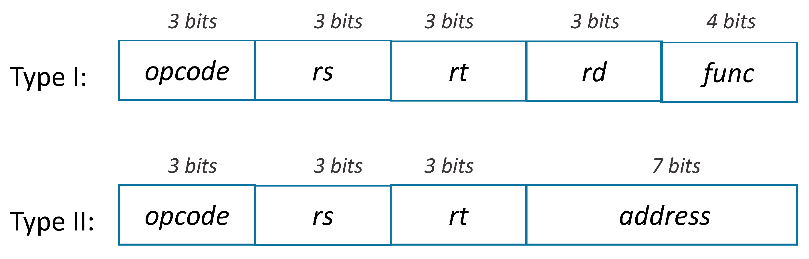
The processor instructions are stored in the instruction memory (block IMemory). There exist just two types of instructions: I and II, as illustrated in Figure 2. All instructions are 16 bits long.
Here is the meaning of each name of the fields in the instructions from Figure 2:
- opcode: basic operation of the instruction, traditionally called the opcode;
- rs: the first register source operand;
- rt: the second register source operand;
- rd: the register destination operand which gets the result of the operation;
- func: function code, selecting the specific variant of the operation in the op field;
- address: constant or address specifies either the offset from the address in the base register rs for data transfer (load/store) instructions or a constant for immediate instructions.
Type I instructions allow for performing an arithmetic or logical operation on two operands read from the rs and rt registers and save the result in the rd register. The func field indicates the type of the operation to be executed. Here are some examples of type I instructions in the suggested assembly language (comments start with “--”):
ADD $rs, $rt, $rd--->>> $rd = $rs + $rt
SUB $rs, $rt, $rd--->>> $rd = $rs − $rt
XOR $rs, $rt, $rd--->>> $rd = $rs $rt
Type II instructions allow for:
- reading the contents of the rt register and saving it in the data memory (DMemory)—SW instruction (save word);
- performing the inverse operation, i.e., reading data from the data memory and storing it in the rt register—LW instruction (load word);
- adding the contents of the rs register with a constant, specified in the address field, and saving the result in the rt register—ADDI instruction (add immediate);
Here are some examples of type II instructions in the suggested assembly language:
SW $rs, $rt, address --->>> DMemory[$rs + address] = $rt
LW $rs, $rt, address --->>> $rt = DMemory[$rs + address]
ADDI $rs, $rt, address --->>> $rt = $rs + address
Different instructions are distinguished by the opcode code according to Table 1. Note that, in addition to instructions of types I and II, there is a special instruction NOP that does nothing.
The func field indicates the type of operation to be performed according to Table 2.
A brief explanation of the available processor instructions is given to the students with simple examples of translating assembly instructions to the corresponding machine code (see examples in Figure 3). It should be noted that this is a first contact of the students with the concepts of assembly, assembler, and binary machine instructions. During the project execution, students receive a short assembly program, which they have to translate to the respective machine code manually. Teachers obviously do not execute this step by hand; instead, a program was developed in Java language automating the translation process [35] and generating directly the specific VHDL code to be used for initialization of the instruction memory.
3.2. Building a Datapath
The major datapath components required to execute the listed in the previous subsection instructions are illustrated in Figure 1. These are as follows:
- PC (Program Counter) is an up counter that holds the address of the next instruction to be executed. The counter is incremented every time a new instruction is fetched from the instruction memory.
- IMemory (Instruction Memory) is a memory unit to store the instructions of a program and supply instructions given an address.
- Registers is a block of eight registers of 8 bits each. Register 0 is a special register—it always keeps the value 0 and cannot be written.
- ALU (Arithmetic and Logic Unit) is a combinational block performing operations listed in Table 2.
- DMemory (Data Memory) is a 256 × 8 memory unit that stores the data of a program.
- SignExtend is a sign extension unit having a 7-bit input that is sign-extended into an 8-bit result appearing on the output.
- Three 2:1 multiplexers that permit sharing a datapath element between different instruction classes.
The operations of arithmetic-logical (or type I) instructions and the type II instructions datapath are quite similar. The key differences are the following [34]:
- The arithmetic-logical instructions use the ALU, with the inputs coming from the two registers. The type II instructions can also use the ALU to do either the address calculation or using a constant in an arithmetical operation, although the second input is the sign extended 7-bit address field from the instruction.
- The value stored into a destination register comes from the ALU (for a type I instructions and ADDI) or the data memory (for the LW instruction).
To create a datapath with only a single register block and a single ALU, two different sources must be supported for the second ALU input, as well as two different sources, are required for the data stored into the register block. In addition, the destination register address may also come either from rd field (for type I instructions) or from rt field (for type II instructions). Thus, one multiplexor is placed at the ALU input, another at the data input to the register block, and the third multiplexer at the write address input of the register block.
The detailed explanation of the intended function of every datapath component is provided to the students (in a dedicated online lecture). Then, the students have to design and test every component and connect them according to Figure 1.
3.3. Building the Control Unit
A control unit, which has the instruction’s opcode and func fields as an input, is used to determine how to set the control lines for the functional units of the datapath. For example, the register block must be written only on a load, ADDI, or an arithmetic-logical instruction so the respective RegWr (register write enable) signal must be activated for these instructions only. Similarly, the ALU must perform one of several operations, and control lines that are set based on various fields in the instructions directing these operations.
The control unit decodes the opcode instruction code and the operation code func and generates control signals (marked in red in Figure 1) according to the state diagram in Figure 4 (for the NOP instructions, all the control signals must be deactivated).
Note that the diagram is intentionally not complete, as it does not specify the active control signals for each of the states. The diagram illustrates that the execution cycle for each instruction includes four steps:
- Fetch—reading an instruction from the instruction memory and updating the program counter;
- Decode—reading contents of the source registers and computing the control lines’ values;
- Execute—performing calculations in the ALU (for example, an arithmetic-logical operation is executed for type I instructions or the calculation of the data memory address is done for SW and LW instructions);
- Update (RegUpdate or WriteMem)—saving the result in a register (for instructions of type I or LW/ADDI) or in memory (for SW).
The detailed explanation of the intended control unit functionality is provided to the students. In particular, step-by-step flows of execution of every instruction are given with all the activated control signals illuminated in the processor’s block diagram. Then, the students have to complete the state diagram and to describe it in VHDL using any of the considered within the LSD course FSM coding styles.
3.4. Implementation Requirements
All the aforementioned explanations are provided in a single two-hour long online lecture. In addition, a video is published on the DDL channel on Educast [32] so that the students may consult the supporting material at their own pace. The students have to design all the datapath and controlpath components in VHDL using the knowledge acquired during the semester and respecting the following requirements:
- The global system reset should only affect (reset) the value of the program counter and the content of all the registers. The memories (for both data and instructions) are not affected by the reset.
- Synchronization must be done with a single clock signal.
- The top-level of the system should be implemented, preferably, using the structural representation in VHDL.
- All the tests must be supported by the respective testbenches developed in VHDL.
The implementation itself is conducted in phases described below:
- Phase 1—implementation and testing of the datapath. The task is to model in VHDL, synthesize, and validate all blocks of the datapath by simulation, trying to create parameterizable components, as this will facilitate future adjustments to the system. An example is the following: “Assume that the instruction memory can store a maximum of eight instructions from the following group: {LW, SW, ADD, SUB, SLS, SLU}. Initialize the data memory with the values: (X “05”, X “04”, others => X “00”). Initialize the instruction memory with the given test program (code the instructions according to Figure 2, Figure 3 and Table 1, Table 2). Connect all the blocks together, as shown in Figure 1, and simulate the behavior of the complete execution unit.”All the underlined statements are different for various students. Successful completion of this phase is evaluated with eight values (out of 20) at the maximum.
- Phase 2—Implementation and testing of the control unit. Students are requested to complete the control unit state diagram from Figure 4, and then to specify in VHDL and to validate the control unit by simulation.Successful completion of this phase is evaluated with four values (out of 20) at the maximum.
- Phase 3—Interconnection and test of the complete processor (datapath + control unit). Interconnection of the control unit and the datapath has to be provided and the entire systems has to be tested in a simulator.Successful completion of the first three phases (which is the expectable minimum result for all the students) is evaluated with 16 values (out of 20) at the maximum.
- Phase 4—Adding a new instruction. At this point, the students are asked to add a new type II instruction, such as BEQ (branch on equal) or BNE (branch on not equal). This point requires some additional study and changes to both the datapath and the control unit and is reserved for the best students who are candidates for grades greater than 16 (out of 20). After adding a new instruction, the student is required to write in assembly a relatively simple program and to prove that their processor correctly executes this. Examples of such a task are (every student gets a different problem):
- ○
- Write a program that finds the largest of three signed numbers stored in the data memory.
- ○
- Write a program that calculates the Hamming distance between two values, stored in the data memory.
- ○
- Write a program that sorts, in ascending order, an array of three signed numbers, stored in the memory.
4. Evaluation Process and Discussion of the Results
Modeling various processor architectures in hardware description languages has been extensively explored in the past for both research and educational purposes [36,37,38,39,40,41,42,43,44,45,46]. The main objective is either developing an open-source application-specific processor (like [42]) or accelerating computer architecture learning process. Definitely, CE students should have a clear understanding of operation of a processor as well as the related tools and software. This understanding can be achieved in a number of ways, but there is a popular belief that a future computer engineer should build at least one processor in their education [39,43]. The project proposed to the students allows for testing all the expected learning outcomes of DDL course, listed in Section 2, and at the same time prepares them for further, more advanced courses, in their curricula. Note that, albeit the suggested processor architecture is very simple, modeling it is not an easy task for students who have no previous training in computer architecture. Moreover, the simple architecture provides sufficient complexity to demonstrate fundamental digital design concepts.
The processor design functions as an obligatory short term project which spans about four weeks at the end of semester (after the students have already obtained laboratory experience with modeling, simulation, and test of typical combinatorial/sequential blocks, memories, and finite-state machines). Totally, eighteen project versions have been created and randomly distributed among the students (with a guarantee that, within every lab, each student gets a different project). At the beginning of the project, students were given the related documentation along with the instruction set architecture. At the same time, a dedicated two-hour long online lecture was organized introducing computer architecture and explaining the proposed processor organization. The lecture recording is also available anytime for students’ consultation. No VHDL code was given to the students as they should have qualifications to model every one of the processor’s units. According to phases detailed in the previous section, for initial tests, a trivial assembly program was given to the students and they were asked to write a small program in assembly to get higher grades. This part permits to test students’ understanding of the difference between hardware and software.
The developed projects have to be submitted to the Moodle platform, accompanied with the respective report, 72 h before the presentation section, which is organized during the last semester’s labs. The project defense is run remotely, over the Zoom platform, and consists of a student’s presentation, demonstration of functionality, and a Q&A section. Two teachers participate in the assessment process and the students are invited one by one to a breakout room so that their colleagues do not become aware of the type of questions that they might receive. The presentations are required to discover whether the students did the project by themselves. Moreover, presentations allow for developing communication skills in the students and to raise their stress strength. Thus, in addition to the digital system design knowledge, projects develop in students a set of soft skills, including writing technical documentation, public presentation, and defense of a technical work.
In 2019/2020, 226 students have been enrolled in DDL course and 155 of them submitted final projects for evaluation. Out of 71 students who did not submit their projects, 14 have already done the lab evaluation in the previous academic year and 57 gave up the course (because of either personal reasons or low marks on theoretical assessment). The submitted 155 projects have been presented and defended in 12 online Zoom sessions spanned over a week period. It turned out to be really simple to assess students as all the involved teachers (six) knew the project very well; therefore, just a brief look through the students’ VHDL code and a couple of questions were sufficient to have an idea about the expected grade. Each student was questioned by two teachers to make the assessment process as objective as possible. In addition, each teacher analyzed in detail the VHDL code, simulation results, and reports of the students in the labs he/she is responsible for. The following evaluation guidelines have been applied (the maximum grade is 20):
- Project presentation and demonstration (50%):
- ○
- 0—missing
- ○
- 4—presentation, defense, and demonstration of very poor quality (badly structured presentation, low quality slides, most questions not answered properly, demonstration completely failed)
- ○
- 8—poor presentation (not clear), questions partially answered, serious flaws in the demonstration
- ○
- 12—reasonable presentation, answer to most questions, demonstration without serious flaws
- ○
- 16—clear and fluid presentation, answer to most questions, demonstration with only a slight flaw
- ○
- 20—presentation of very good quality and well structured, with good slides and figures, answer to all questions and impeccable demonstration (fluid and without fails)
- Project quality (35%)
- ○
- 0—missing
- ○
- 4—very weak work/not functional/with syntax errors
- ○
- 8—partially functional work, but with serious functional errors
- ○
- 12—partially functional work, but with slight functional errors
- ○
- 16—fully functional work, fulfilling the specification and with acceptable structure
- ○
- 20—fully functional work, very well structured and that exceeds the specification
- Report (15%)
- ○
- 0—not delivered
- ○
- 4—very weak report, without several mandatory sections; the system that was developed is not described in an understandable manner
- ○
- 8—weak report, hardly comprehensible and without figures
- ○
- 12—reasonably understandable report, poor quality figures
- ○
- 16—quality report in which the work carried out is clearly explained both in text and with useful supporting figures
- ○
- 20—excellent report with a clear and concise system description, including figures, results, and conclusions
The maximum grade that a student can get is limited by thresholds indicated in Section 3.4 (8 values for phase 1; 12 values for phases 1 and 2; 16 values for phases 1–3; and 20 values for phases 1–4).
Albeit the evaluation process ran very smoothly and every teacher cross-checked the projects in the labs he/she is responsible for, it turned out that a global plagiarism detection mechanism is required. Manual checking of 155 projects by a single teacher is not feasible; therefore, we applied an automatic freely available plagiarism detection software JPlag [47]. JPlag is designed to find similarities among student solutions by comparing multiple sets of source code files taking into account popular programming languages syntax and typical program structure. Although VHDL is not directly supported by JPlag, we found VHDL files to be very suitable for this type of check as the tool was able to detect both directly copied or slightly modified code fragments. As a result, we encountered five cases (two clusters) of (almost 100%) plagiarism among our students. These students were invited for an online clarification section where they were asked for explanation and defense of their position. All of them finally admitted that they developed their projects together and a decision was made to punish all these students with the final grade 0. Unfortunately, we also discovered that many other students shared copies of VHDL specifications of one-two processor’s units, but decided that this is an admissible situation with so many people working on a common project.
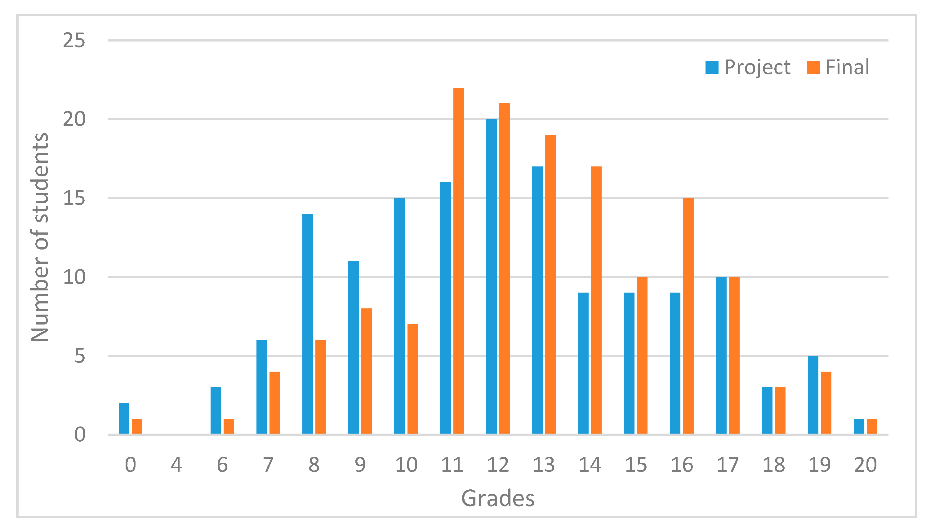
The project grades of the remaining 150 students are distributed as illustrated in the histogram in Figure 5. The final course grades (including project, theoretical, and lab evaluation) are also shown in Figure 5 (for the same group of students). All the students who received less than eight values for the project or less than 10 as the final mark, are considered reproved. The positive student assessment results are indeed better than in the previous years, which is coherent with the results reported in [13,14,15,16,20], but the percentage of reproved students is almost the same as before.
In our university, the assessment of the teaching-learning process is a crucial tool in controlling and guaranteeing the quality of education. Upon the end of each semester, the students have to respond to an obligatory pedagogical survey for every course they have been enrolled to. The survey includes questions about teachers and the course itself and requires the students to rate their experience on a scale from 1 to 9. Examples of questions are:
- Creating a favorable environment for students to learn
- Stimulating student autonomy
- Monitoring student work
- Clarity of exposure
- Compliance with the assessment rules agreed with students
- Availability of information on Moodle
- Adequacy and modernity of lab equipment
In 2019/2020, the DDL course obtained the best classification results over the span of the previous five years by CE students. The overall course classification grew from 6.71 points in 2016/2017 to 6.96 points in 2019/2020. The reported points represent a mean of different course-functioning criteria assessed by the students after completing the course.
In the final student commission evaluation report, it was pointed out that the proposed project was interesting and useful. This is coherent with other related PBL experiences [13,14,15,16,17,18,19,20,21] that demonstrated that the students, albeit having more workload, acquire additional skills. At this point, we do not have any evidence of whether the project experience have had any positive effect on the running in the 1st semester of 2020/2021 course on computer architecture.
5. Conclusions
In this paper, we describe a project-based learning experience applied within a course on digital design using high-capacity programmable devices. We consider that the proposed processor-modelling project is very suitable to test the expected learning outcomes of the DDL course because of the following reasons:
- The processor instruction-set architecture was defined specifically for this course, so it is not so easy to find and copy similar designs.
- To accomplish the project, the students have to apply effectively the learned during the course coding styles for modeling combinational/sequential blocks and finite state machines.
- The students have to become proficient with the use of computer-aided design tools for the purposes of modeling, simulation, synthesis, testing, and optimization.
- The previous points prove that the students are forced to learn and use the intended content knowledge avoiding a situation where some important items of course content are not learned.
- From a future work perspective, a number of extensions may easily be proposed to this project, such as adding new instructions, improving the base architecture, creating supporting software tools (e.g., assembler), etc. These extensions are applied within the following course on computer architecture.
- With no possibility to use the development kits due to the COVID-19 pandemic, this project is well suited for verification and testing through simulation and for remote learning and assessment.
- The teachers can easily assess the projects and plagiarism is almost effortlessly detectable.
- Student feedback is positive such that the project permits experimenting with basic design concepts without unnecessary complexity.
- The results indicate that most of the students completed at least the first three phases of the processor design successfully. Only a few students stated that tasks were relatively difficult and required additional help.
- Overall, students got extra motivation by immediately running the processors they designed and seeing the result as the level of satisfaction when seeing a system doing something useful is naturally much higher compared to the design and testing of individual albeit useful components.
- As a drawback, we should point out that the students get limited practical experience with digital design based on FPGA with no possibility to discover that even a correctly simulated circuit might not function as expected. This is an inevitable consequence of COVID-19 limitations. When restrictions are lifted, the processor project might easily be adapted to be implemented and tested on DE2-115 boards.
- The project-based learning permits to shift from teacher-directed learning adopted in theoretical classes and labs to student-centered experience, where the teacher’s role is not as the leader but rather as the facilitator and the students take a more active role in constructing their own knowledge. This leads to deeper understanding and depth of knowledge where all the information that they are receiving in classes is going to be something that is meaningful to them because they have constructed it.
- The results reported in Section 4 prove the efficiency of the adopted project-based learning strategy.
Funding
This work was supported by the National Funds through the FCT—Foundation for Science and Technology, in the context of the project UIDB/00127/2020.
Conflicts of Interest
The author declares no conflict of interest.
References
- Computer EngineeringCurricula 2016 Curriculum Guidelines for Undergraduate Degree Programs in Computer Engineering. Available online: https://www.acm.org/binaries/content/assets/education/ce2016-final-report.pdf (accessed on 19 January 2021).
- Computer Science Curricula 2013 Curriculum Guidelines for Undergraduate Degree Programs in Computer Science. Available online: https://www.acm.org/binaries/content/assets/education/cs2013_web_final.pdf (accessed on 19 January 2021).
- Computing Curricula 2020 (CC2020) Paradigms for Future Computing Curricula. Available online: https://cc2020.nsparc.msstate.edu/wp-content/uploads/2020/11/Computing-Curricula-Report.pdf (accessed on 19 January 2021).
- Intel, Corp. Quartus Prime Software. Available online: https://www.intel.com/content/www/us/en/programmable/downloads/download-center.html (accessed on 19 January 2021).
- Intel, Corp. Altera DE2-115 Development and Education Board. Available online: https://www.intel.com/content/www/us/en/programmable/solutions/partners/partner-profile/terasic-inc-/board/altera-de2-115-development-and-education-board.html (accessed on 19 January 2021).
- Xilinx, Inc. Zynq-7000 All Programmable SoC. Available online: https://www.xilinx.com/products/silicon-devices/soc/zynq-7000.html (accessed on 19 January 2021).
- Skliarova, I.; Sklyarov, V.; Sudnitson, A.; Kruus, M. Teaching FPGA-based Systems. In Proceedings of the 2014 IEEE Global Engineering Education Conference (EDUCON), Istanbul, Turkey, 3–5 April 2014; pp. 460–469. [Google Scholar] [CrossRef]
- Sklyarov, V.; Skliarova, I. Teaching Reconfigurable Systems: Methods, Tools, Tutorials and Projects. IEEE Trans. Educ. 2005, 48, 290–300. [Google Scholar] [CrossRef]
- Sklyarov, V.; Skliarova, I.; Sudnitson, A.; Kruus, M. Reconfigurable Systems in Engineering Education: Best Practices and Future Trends. In Proceedings of the 2017 IEEE Global Engineering Education Conference (EDUCON), Athens, Greece, 25–28 April 2017; pp. 1079–1083. [Google Scholar] [CrossRef]
- Sklyarov, V.; Skliarova, I.; Sudnitson, A. Methodology and International Collaboration in Teaching Reconfigurable Systems. In Proceedings of the 2012 IEEE Global Engineering Education Conference (EDUCON), Marrakesh, Morocco, 17–20 April 2012; pp. 1143–1152. [Google Scholar] [CrossRef]
- Skliarova, I.; Sklyarov, V.; Sudnitson, A.; Kruus, M. Integration of High-Level Synthesis to the Courses on Reconfigurable Digital Systems. In Proceedings of the 2015 38th International Convention on Information and Communication Technology, Electronics and Microelectronics (MIPRO), Opatija, Croatia, 25–29 May 2015; pp. 172–177. [Google Scholar] [CrossRef]
- Skliarova, I. Teaching Digital Design—A Case Study of Exploring Booth Algorithm. In Proceedings of the International Scientific and Practical Conference “Computer Science and Applied Mathematics”, Almaty, Kazakhstan, 27–30 September 2017; pp. 74–86. [Google Scholar]
- Debiec, P. Effective Learner-Centered Approach for Teaching an Introductory Digital Systems Course. IEEE Trans. Educ. 2018, 61, 38–45. [Google Scholar] [CrossRef]
- Todorovich, E.; Marone, J.A.; Vázquez, M. Introducing Programmable Logic to Undergraduate Engineering Students in a Digital Electronics Course. IEEE Trans. Educ. 2012, 55, 90–97. [Google Scholar] [CrossRef]
- Jordana, J.; Robert, F.J. A Course on Digital Electronics Based on Solving Design-Oriented Exercises by Means of a PBL Strategy. Int. J. Eng. Educ. 2015, 31, 238–247. [Google Scholar]
- Arias, M.; Rodríguez, A.; Lamar, D.G.; Linera, F.; Hernando, M. Influence of PBL practical classes on microcontroller-based digital systems learning. In Proceedings of the IEEE EDUCON 2010 Conference, Madrid, Spain, 14–16 April 2010; pp. 1777–1782. [Google Scholar] [CrossRef]
- Suryawan, F. A Project-Based Approach to FPGA-Aided Teaching of Digital Systems. In Proceedings of the 2017 4th International Conference on Electrical Engineering, Computer Science and Informatics (EECSI), Yogyakarta, Indonesia, 19–21 September 2017; pp. 561–566. [Google Scholar] [CrossRef]
- Cetin, E.; Wijenayake, C.; Sethu, V.; Ambikairajah, E. A Flipped Mode Approach to Teaching an Electronic System Design Course. In Proceedings of the 2017 IEEE 6th International Conference on Teaching, Assessment, and Learning for Engineering (TALE), Hong Kong, China, 12–14 December 2017; pp. 223–228. [Google Scholar] [CrossRef]
- Chua, D.; Gao, J.; Alioto, M.; Xu, Y.P.; Sasidhar, S. Project-Based Learning in Digital Fundamentals Course Using FPGAs. In Proceedings of the 2018 IEEE Frontiers in Education Conference (FIE), San Jose, CA, USA, 3–6 October 2018; pp. 223–228. [Google Scholar] [CrossRef]
- Matutino, P.M.; Dias, T.; Sampaio., P. Teaching Hardware/Software Co-Design Using a Project-Based Learning Strategy. In Proceedings of the 2020 XIV Technologies Applied to Electronics Teaching Conference (TAEE), Porto, Portugal, 8–10 July 2020; pp. 223–228. [Google Scholar] [CrossRef]
- Seo, D.; Mangra, D. Project-Based Learning of Digital Logic Circuit Design. In Proceedings of the Fall 2017 Mid-Atlantic ASEE Conference, Reading, PA, USA, 6–7 October 2017; pp. 223–228. Available online: https://peer.asee.org/project-based-learning-of-digital-logic-circuit-design.pdf (accessed on 18 February 2021).
- Valiente, D.; Payá, L.; Ávila, S.F.; Ferrer, J.C.; Reinoso, O. Analysing Students’ Achievement in the Learning of Electronics Supported by ICT Resources. Electronics 2019, 8, 264. [Google Scholar] [CrossRef] [Green Version]
- Zhang, Y.; Dang, Y.; Amer, B. A Large-Scale Blended and Flipped Class: Class Design and Investigation of Factors Influencing Students’ Intention to Learn. IEEE Trans. Educ. 2016, 59, 263–273. [Google Scholar] [CrossRef]
- Zhang, Z.; Hansen, C.T.; Andersen, M.A. Teaching Power Electronics with a Design-Oriented, Project-Based Learning Method at the Technical University of Denmark. IEEE Trans. Educ. 2016, 59, 32–38. [Google Scholar] [CrossRef] [Green Version]
- Amiel, F.; Abboud, D.; Trocan, M. A project oriented learning experience for teaching electronics fundamentals. IEEE Commun. Mag. 2014, 52, 98–100. [Google Scholar] [CrossRef]
- Zhong, X.; Liang, Y. Raspberry Pi: An Effective Vehicle in Teaching the Internet of Things in Computer Science and Engineering. Electronics 2016, 5, 56. [Google Scholar] [CrossRef]
- Almulla, M.A. The Effectiveness of the Project-Based Learning (PBL) Approach as a Way to Engage Students in Learning. SAGE Open 2020, 10. [Google Scholar] [CrossRef]
- Ngo, H.Q.T.; Phan, M.-H. Design of an Open Platform for Multi-Disciplinary Approach in Project-Based Learning of an EPICS Class. Electronics 2019, 8, 200. [Google Scholar] [CrossRef] [Green Version]
- Phan, M.-H.; Ngo, H.Q.T. A Multidisciplinary Mechatronics Program: From Project-Based Learning to a Community-Based Approach on an Open Platform. Electronics 2020, 9, 954. [Google Scholar] [CrossRef]
- Lamo, P.; de Castro, Á.; Brañas, C.; Azcondo, F.J. Emulator of a Boost Converter for Educational Purposes. Electronics 2020, 9, 1883. [Google Scholar] [CrossRef]
- Block, B.M.; Haus, B. New ways in engineering education for a sustainable and smart future. In Proceedings of the 2020 IEEE Frontiers in Education Conference (FIE), Uppsala, Sweden, 21–24 October 2020; pp. 1–9. [Google Scholar] [CrossRef]
- Digital Design Laboratory channel on Educast. 2020. Available online: https://educast.fccn.pt/channels/6273/clips?locale=en (accessed on 20 January 2021).
- O’Connell, R.M. Adapting Team-Based Learning for Application in the Basic Electric Circuit Theory Sequence. IEEE Trans. Educ. 2015, 58, 90–97. [Google Scholar] [CrossRef]
- Hennessy, J.; Patterson, D.A. Computer Organization and Design—The Hardware/Software Interface, 5th ed.; Morgan Kaufmann: Oxford, UK, 2014. [Google Scholar]
- Skliarova, I. Java Program Converting Assembly to Machine Code for a MIPS Processor. Available online: https://github.com/iouliia/MIPSAssembly2MachineCode/tree/main (accessed on 21 January 2021).
- Rodríguez, W.S.; Sánchez, F.R.; Santa, F.M. 8-bit softcore microprocessor with dual accumulator designed to be used in FPGA. Tecnura 2018, 22, 40–55. [Google Scholar] [CrossRef]
- Hayne, R.J. Translating the Instructional Processor from VHDL to Verilog. ASEE Comput. Educ. J. (CoED) 2018, 9, 1–6. [Google Scholar]
- Kostadinov, N.; Bencheva, N. An Approach for Teaching Processor Design and How to Extend its Features. In Proceedings of the 2019 29th Annual Conference of the European Association for Education in Electrical and Information Engineering (EAEEIE), Ruse, Bulgaria, 4–6 September 2019; pp. 1–4. [Google Scholar] [CrossRef]
- Yıldız, A.; Ugurdag., H.F.; Aktemur, B.; İskender, D.; Gören, S. CPU design simplified. In Proceedings of the 2018 3rd International Conference on Computer Science and Engineering (UBMK), Sarajevo, Bosnia and Hercegovina, 20–23 September 2018; pp. 630–632. [Google Scholar] [CrossRef]
- Mazurek, P. BOSON—Application-Specific Instruction Set Processor (ASIP) for Educational Purposes. In Proceedings of the 2020 16th International Conference on Control Automation, Robotics and Vision (ICARCV), Shenzhen, China, 13–15 December 2020; pp. 1323–1328. [Google Scholar] [CrossRef]
- Graff, N. TurtleMCU: A Platform for Teaching a Holistic View into Embedded Computer Architecture and Security. In Proceedings of the 2018 IEEE Frontiers in Education Conference (FIE), San Jose, CA, USA, 3–6 October 2018; pp. 1–5. [Google Scholar] [CrossRef]
- Isola, L. Design and VHDL Implementation of an Application-Specific Instruction Set Processor. Master’s Thesis, School of Electrical Engineering, Aalto University, Helsinki, Finland, 2020. [Google Scholar]
- McGrew, T.; Schonauer, E.; Jamieson, P. Framework and Tools for Undergraduates Designing RISC-V Processors on an FPGA in Computer Architecture Education. In Proceedings of the 2019 International Conference on Computational Science and Computational Intelligence (CSCI), Las Vegas, NV, USA, 5–7 December 2019; pp. 778–781. [Google Scholar] [CrossRef]
- Kadam, S.U.; Mali, S.D. Design of RISC Processor Using VHDL. Int. J. Res. Granthaalayah 2016, 4, 131–138. [Google Scholar] [CrossRef]
- Kaur, N.; Kumar, A.; Gupta, L. VHDL Design and Synthesis of 64 bit RISC Processor System on Chip (SoC). IOSR J. VLSI Signal Process. 2013, 3, 31–42. [Google Scholar] [CrossRef]
- Thakor, K.P.; Pal, A. Design of a 16-bit RISC Processor Using VHDL. Int. J. Eng. Res. Technol. (IJERT) 2017, 6. [Google Scholar] [CrossRef]
- JPlag—Detecting Software Plagiarism. Available online: https://github.com/jplag/jplag (accessed on 23 January 2021).
Figure 1.
Block diagram of the processor to model.

Figure 2.
The supported instruction types.

Figure 4.
Incomplete state diagram of the control unit.

Figure 5.
Histogram of the project/final grades.

Figure 3.
Examples of instruction encoding: (a) type I; (b) type II; (c) a short assembly program given to students for translation to the machine code; (d) the result of conversion to machine code in the format of VHDL code to be used for initialization of the instruction memory.
Figure 3.
Examples of instruction encoding: (a) type I; (b) type II; (c) a short assembly program given to students for translation to the machine code; (d) the result of conversion to machine code in the format of VHDL code to be used for initialization of the instruction memory.


Table 1.
Opcode field value for different instructions.
| Opcode | Instruction |
|---|---|
| 000 | NOP—do nothing |
| 001 | All arithmetic or logical instructions (the operation to be performed is defined by the func field)—type I instruction |
| 100 | ADDI—add immediate, adds the contents of a register to a constant—type II instruction |
| 110 | SW—transfer data from a register to the data memory—type II instruction |
| 111 | LW—transfer data from the data memory to a register—type II instruction |
Table 2.
Operations supported by the ALU.
| func | Operation |
| 0000 | ADD—sum |
| 0001 | SUB—subtraction |
| 0010 | AND |
| 0010 | OR |
| 0100 | XOR |
| 0101 | NOR |
| 0110 | MUU—unsigned multiplication (only the least significant half of the result is used) |
| 0111 | MUS—signed multiplication (only the least significant half of the result is used) |
| 1000 | SLL—shift left logical of $rs by $rt bits |
| 1001 | SRL—shift right logical of $rs by $rt bits |
| 1010 | SRA—shift right arithmetical of $rs by $rt bits |
| 1011 | EQ—equal—the result is 1 if $rs = $rt, otherwise 0 |
| 1100 | SLS—set on less than signed—the result is 1 if signed ($rs) < signed($rt), otherwise 0 |
| 1101 | SLU—set on less than unsigned—the result is 1 if unsigned ($rs) < unsigned($rt), otherwise 0 |
| 1110 | SGS—set on greater than signed—the result is 1 if signed ($rs) > signed($rt), otherwise 0 |
| 1111 | SGU—set on greater than unsigned—the result is 1 if unsigned ($rs) > unsigned($rt), otherwise 0 |
Publisher’s Note: MDPI stays neutral with regard to jurisdictional claims in published maps and institutional affiliations. |
© 2021 by the author. Licensee MDPI, Basel, Switzerland. This article is an open access article distributed under the terms and conditions of the Creative Commons Attribution (CC BY) license (http://creativecommons.org/licenses/by/4.0/).
Share and Cite
MDPI and ACS Style
Skliarova, I. Project-Based Learning and Evaluation in an Online Digital Design Course. Electronics 2021, 10, 646. https://doi.org/10.3390/electronics10060646
AMA Style
Skliarova I. Project-Based Learning and Evaluation in an Online Digital Design Course. Electronics. 2021; 10(6):646. https://doi.org/10.3390/electronics10060646
Chicago/Turabian StyleSkliarova, Iouliia. 2021. "Project-Based Learning and Evaluation in an Online Digital Design Course" Electronics 10, no. 6: 646. https://doi.org/10.3390/electronics10060646
Note that from the first issue of 2016, this journal uses article numbers instead of page numbers. See further details here.