Article

A Quad-Port Dual-Band MIMO Antenna Array for 5G Smartphone Applications

College of Electrical and Electronics Engineering, Wenzhou University, Wenzhou 325035, China
*
Author to whom correspondence should be addressed.
Electronics 2021, 10(5), 542; https://doi.org/10.3390/electronics10050542
Submission received: 7 February 2021 / Revised: 18 February 2021 / Accepted: 23 February 2021 / Published: 25 February 2021
(This article belongs to the Special Issue Antenna Designs for 5G/IoT and Space Applications)

Abstract

:
A quad-port antenna array operating in 3.5 GHz band (3.4–3.6 GHz) and 5 GHz band (4.8–5 GHz) for fifth-generation (5G) smartphone applications is presented in this paper. The single antenna element consists of an L-shaped strip, a parasitic rectangle strip, and a modified Z-shaped strip. To reserve space for 2G/3G/4G antennas, the quad-port antenna array is printed along the two long frames of the smartphone. The evolution design and the analysis of the optimal parameters of a single antenna element are derived to investigate the principle of the antenna. The prototype of the presented antenna is tested and the measured results agree well with the simulation. The measured total efficiency is better than 70% and the isolation is larger than 16.5 dB.

1. Introduction

With the increasing demand for the quality of wireless communication, the fifth-generation (5G) mobile communication technology provides a promising solution to higher transmission rates, shorter latency, more connection density, and larger communication capacity. Recently, many 5G sub-6 GHz Multiple-Input Multiple-Output (MIMO) antennas have been developed for mobile terminals and base stations [1,2,3,4,5]. However, with the limited internal space of mobile phones, it is a challenging task to integrate many antennas with high isolation and low envelope correlation coefficient. Dual-band four-port MIMO antenna can expand system capacity and realize multi-mode communication. To minimize the unwanted mutual coupling, various isolation techniques have been reported in recent years [3,4,5,6,7,8,9,10,11,12,13,14]. The rectangle slots of the defected ground plane and two rectangular microstrip lines are employed to decrease the mutual coupling in [3]. In [4], the vertical patch is used to offset the coupling between the antenna and nearby components. A ground-connected T-shaped decoupling stub and an additional modified T-shaped decoupling stub is inserted between the two mirrored dual-antenna arrays to reduce the coupling in [5]. By introducing two short T-shaped strips and a π-shaped strip, the isolation between two antenna elements is enhanced [6]. An inverted-F antenna is used to reduce the mutual coupling of antenna elements [7]. Other decoupling techniques have also been presented, such as using a short neutral line [8,9], high-pass filter [10], pattern diversity [11], self-decoupling [12], defected ground structure [13], and metamaterial structure [14].
In the World Radiocommunication Conference 2015, the 3.5 GHz (3.4–3.6 GHz) frequency band became one of the 5G mobile phone spectrums. The Ministry of Industry and Information Technology of China approved 3.3–3.6 GHz and 4.8–5 GHz as the sub-6 GHz 5G frequency bands. Moreover, except for the sub-6-GHz spectrum, 5G smartphones are also expected to be phased array millimeter-wave antenna at 28 GHz frequency band [15].
In this paper, a novel dual-band antenna operating at 3.5 GHz band (3.4–3.6 GHz) and 5 GHz band (4.8–5 GHz) is proposed for the applications of a 5G MIMO antenna in smartphones. The proposed antenna shows high isolation, high gain and low ECC, which can be used to achieve high transmission rates and large channel capacity. The proposed antenna array consists of an L-shaped feeding strip, a parasitic rectangle strip, and a modified Z-shaped radiating strip. Different evaluative structures and optimal parameter analysis are carried out for the proposed compact quad-port dual-band MIMO antenna.

2. Antenna Geometry

The geometry of the proposed quad-port dual-band MIMO antenna array is shown in Figure 1. There are two types of printed circuit boards (PCBs) including a main board and two side boards, as depicted in Figure 1a. The size of the main board is 150 mm × 75 mm × 0.8 mm, and the size of the side board is 150 mm × 6.2 mm × 0.8 mm. Four antenna elements are printed on two side boards which are positioned vertically to the main board. Both the side boards and the main board are printed on an FR4 substrate with εr = 4.4 and tan δ = 0.02. The side boards are bonded with the main boards by metal adhesive. Other spaces of both frames (side boards) are reserved for 2G/3G/4G or other wireless communication antennas in the mobile handsets. Figure 1b shows the detailed dimensions of single antenna element. The single antenna element includes a L-shaped feed strip, a parasitic rectangular strip and a modified Z-shaped radiation strip which is connected to the ground plane. The total size of a single antenna element is 14.9 mm × 7 mm × 0.8 mm.

3. Antenna Analysis

In order to understand the mechanism of the proposed MIMO antenna, the design evolution of the antenna element and the optimal parameter analysis are both carried out. Since the structure of the four antenna elements is identical, the parameters of a single element are used for analysis. The 3D full-wave electromagnetic simulator HFSS is used for design and optimization.

3.1. Analysis of the Design Evolution of the Proposed Antenna Element

The proposed antenna is generated by the evolution demonstrated in Figure 2. Ant. 1 is a structure composed of an L-shaped feeding strip and a Z-shaped radiation strip. By adding a parasitic rectangle strip to Ant. 1, Ant. 2 is obtained. Compared with Ant. 2, Ant. 3 has an additional L-shaped strip. The gaps between the L-shaped and Z-shaped strip are 0.5 mm and 0.2 mm, respectively. Compared with Ant. 3, Ant. 4 cuts a rectangular slit on the additional L-shape strip.
Figure 3 depicts the simulated S11 parameters of the evolution antennas. It can be seen that parasitic rectangular strip can increase the bandwidth, and L-shaped strip can create a 3.4 GHz resonant point. Furthermore, the modified Z-shaped strip can shift the frequency band to the higher frequencies which can cover 4.9 GHz (4.8–5 GHz) frequency band.

3.2. Analysis of the Variables of the Proposed Antenna Element

Figure 4 and Figure 5 show simulated S11 of a single antenna element as a function of L and H, respectively. The value of L can be effectively used to change the resonant frequency of the lower frequency band. The higher resonance of a single element can be optimized by tuning the value of H. Eventually, the antenna can operate at frequencies ranging from 3.4 GHz to 3.6 GHz and 4.8 GHz to 5 GHz.

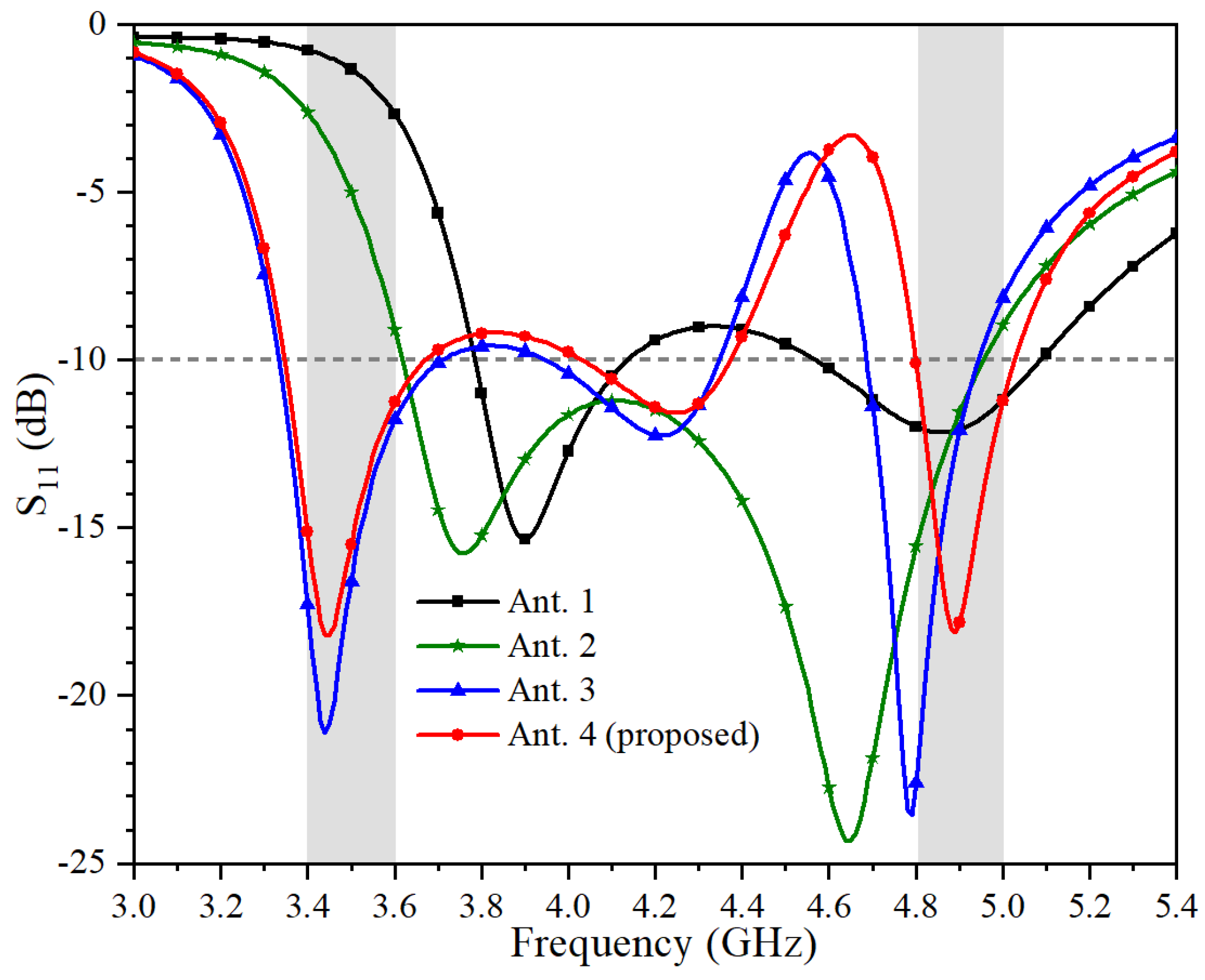
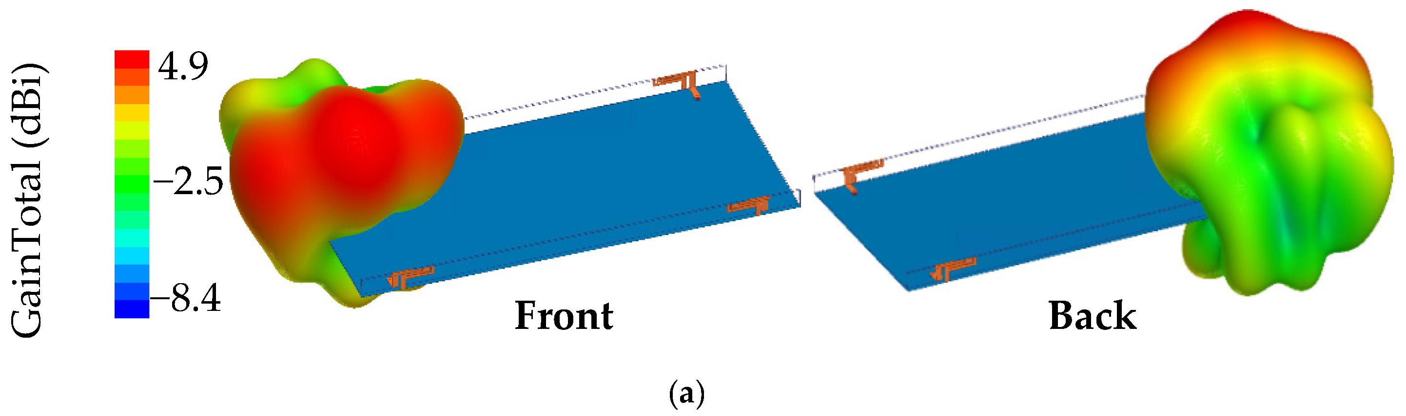
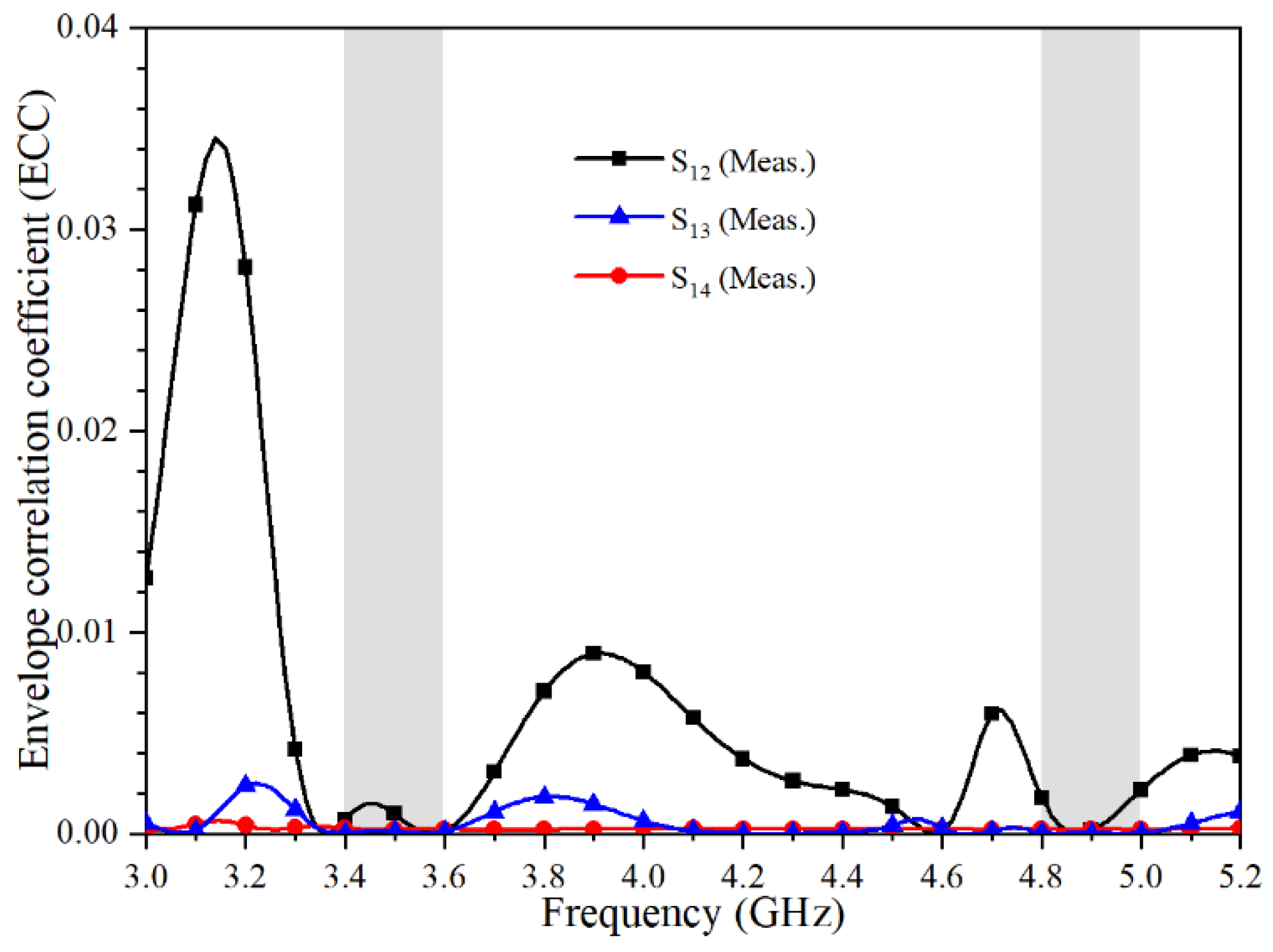
4. Experimental Results and Discussion

To verify the proposed design, an antenna prototype was fabricated using the optimized dimensions listed in Figure 1. Figure 6 is the photograph of the prototype antenna.
Figure 7 shows the S-parameters which are measured by Keysight Vector Network Analyzer N5224A. It can be seen that the measured S11 can cover both 3.5 GHz (3.4–3.6 GHz) and 4.9 GHz (4.8–5 GHz) frequency bands, and the isolation is higher than 16.5 dB. The measured isolation between various ports agrees well with the simulated results. The slight frequency offset is mainly due to SMA connective errors.
In Figure 8, the simulated surface current at 3.5 GHz is mainly distributed at the gap between the rectangular strip and the Z-shaped strip. At 4.9 GHz, strong current intensity is observed at the gap between the L-shaped strip and the modified Z-shaped strip. The distribution of the electric field is mostly the same as the distribution of electric current.
The radiation patterns of the proposed antenna element at 3.5 GHz and 4.9 GHz are shown in Figure 9, respectively. The measured co-pol and cross-pol are represented by different symbol lines. E-plane represents the direction in which the feed current flows, and H-plane is perpendicular to that direction. As shown in the E-plane radiation patterns of Figure 9b, the radiation between the feeding strip and the ground is taken into account, resulting in a similar gain between the co-pol and cross-pol.
In Figure 10, the 3D radiation patterns of a single antenna element as seen from the front side and back side of the substrate are presented, respectively. The maximum gain at 3.5 GHz and 4.9 GHz are 4.9 dBi and 5.1 dBi, respectively. The gains are high enough to meet the requirements of most mobile phone antennas.
The measured total efficiency and peak gain, as shown in Figure 11, are better than 70% and 4 dBi, respectively. The 3.5 GHz and 4.9 GHz frequency points obtain the maximum total efficiency about 85% and 82%, respectively, while the 3.6 GHz and 5 GHz frequency points have the maximum peak gain about 4.7 dBi and 5 dBi, respectively. The measured efficiency is generally lower than that of simulation, which is mainly due to the current skin effect caused by excess solder and the loss of the chamber. The measured total efficiency and peak gain are in good agreement with the simulation results.
The envelope correlation coefficient (ECC) between radiating elements is a critical parameter of the MIMO antenna. The ECC can be calculated by the measured S-parameters according to the below equation.
E C C = | S * m m S m n + S * m m S m n | 2 ( 1 | S m m | 2 | S n m | 2 ) ( 1 | S n n | 2 | S m n | 2 )              
The calculated ECC of the proposed MIMO antenna is shown in Figure 12. The values of ECC in the working frequency bands are all smaller than 0.01, which means that the proposed quad-port MIMO antenna achieves good MIMO diversity performance.
Table 1 shows the performance comparison between the proposed antenna and the previously reported smartphone MIMO antennas. It could be concluded from Table 1 that the proposed MIMO antenna had high isolation, high efficiency and low ECC performance.

5. Conclusions

In this paper, a quad-port MIMO antenna covering 3.5 GHz (3.4–3.6 GHz) and 4.9 GHz (4.8–5 GHz) frequency bands is proposed. The proposed antenna is printed on two long frames of the smartphone, which reserves some space for other wireless communication antennas. The antenna is verified by both simulation and measurement. The size of a single antenna element is only 14.9 mm × 7 mm × 0.8 mm. The measured maximum peak gain at 3.6 GHz and 5 GHz are 4.7 dBi and 5 dBi, respectively. The measured total efficiency is greater than 70% and the isolation is better than 16.5 dB. The proposed MIMO antenna is a good candidate for 5G mobile handsets.

Author Contributions

Conceptualization, J.H.; methodology, G.L.; investigation, G.D., J.C.; writing—original draft preparation, J.H.; writing—review and editing, H.L., G.L.; supervision and funding acquisition, G.L. All authors have read and agreed to the published version of the manuscript.

Funding

This work was supported in part by National Natural Science Foundation of China under Grant No. 61671330and No. 61340049, the Science and Technology Department of Zhejiang Province under Grant No. LGG19F010009, and Wenzhou Municipal Science and Technology Program under Grant No. C20170005 and No.2018ZG019.

Data Availability Statement

The data presented in this study are available on request from the corresponding author.

Conflicts of Interest

The authors declare no conflict of interest.

References

  1. Li, R.; Mo, Z.; Sun, H.; Sun, X.; Du, G. A low-profile and high-isolated MIMO antenna for 5G mobile terminal. Micromachines 2020, 11, 360. [Google Scholar] [CrossRef] [PubMed] [Green Version]
  2. Abdullah, M.; Kiani, S.H.; Abdulrazak, L.F.; Iqbal, A.; Bashir, M.A.; Khan, S.; Kim, S. High-performance multiple-input multiple-output antenna system for 5G mobile terminals. Electronics 2019, 8, 1090. [Google Scholar] [CrossRef] [Green Version]
  3. Barani, I.R.R.; Wong, K. Integrated inverted-F and open-slot antennas in the metal-framed smartphone for 2 × 2 LTE LB and 4 × 4 LTE M/HB MIMO operations. IEEE Trans. Antennas Propag. 2018, 66, 5004–5012. [Google Scholar] [CrossRef]
  4. Liu, D.Q.; Zhang, M.; Luo, H.J.; Wen, H.L.; Wang, J. Dual-band platform-free PIFA for 5G MIMO application of mobile devices. IEEE Trans. Antennas Propag. 2018, 66, 6328–6333. [Google Scholar] [CrossRef]
  5. Cui, L.; Guo, J.; Liu, Y.; Sim, C.Y.D. An 8-element dual-band MIMO antenna with decoupling stub for 5G smartphone applications. IEEE Antennas Wirel. Propag Lett. 2019, 18, 2095–2099. [Google Scholar] [CrossRef]
  6. Bai, J.; Zhi, R.; Wu, W.; Shangguan, M.; Wei, B.; Liu, G. A Novel Multiband MIMO Antenna for TD-LTE and WLAN Applications. Prog. Electromagn. Res. 2018, 74, 131–136. [Google Scholar] [CrossRef] [Green Version]
  7. Wu, W.; Zhi, R.; Chen, Y.; Li, H.; Liu, G. A Compact Multiband MIMO Antenna for IEEE 802.11 a/b/g/n Applications. Prog. Electromagn. Res. 2019, 84, 59–65. [Google Scholar] [CrossRef] [Green Version]
  8. Serghiou, D.; Khalily, M.; Singh, V.; Araghi, A.; Tafazolli, R. Sub-6 GHz dual-band 8 × 8 MIMO antenna for 5G smartphones. IEEE Antennas Wirel. Propag. Lett. 2020, 19, 1546–1550. [Google Scholar] [CrossRef]
  9. Guo, J.; Cui, L.; Li, C.; Sun, B. Side-edge frame printed eight-port dual-band antenna array for 5G smartphone applications. IEEE Trans. Antennas Propag. 2018, 66, 7412–7417. [Google Scholar] [CrossRef]
  10. Xiao, F.; Lin, X.; Su, Y. Dual-band structure-shared antenna with large frequency ratio for 5G communication applications. IEEE Antennas Wirel. Propag Lett. 2020, 19, 2339–2343. [Google Scholar] [CrossRef]
  11. Xu, Z.; Deng, C. High-isolated MIMO antenna design based on pattern diversity for 5G Mobile terminals. IEEE Antennas Wirel. Propag. Lett. 2020, 19, 467–471. [Google Scholar] [CrossRef]
  12. Sun, L.; Li, Y.; Zhang, Z.; Wang, H. Self-decoupled MIMO antenna pair with shared radiator for 5G smartphones. IEEE Trans. Antennas Propag. 2020, 68, 3423–3432. [Google Scholar] [CrossRef]
  13. Xing, H.; Wang, X.; Gao, Z.; An, X.; Zheng, H.; Wang, M.; Li, E. Efficient isolation of an MIMO antenna using defected ground structure. Electronics 2020, 9, 1265. [Google Scholar] [CrossRef]
  14. Iqbal, A.; Saraereh, O.A.; Bouazizi, A.; Basir, A. Metamaterial-based highly isolated MIMO antenna for portable wireless applications. Electronics 2018, 7, 267. [Google Scholar] [CrossRef] [Green Version]
  15. Parchin, N.O.; Basherlou, H.J.; Abd-Alhameed, R.A. Design of multi-mode antenna array for use in next-generation mobile handsets. Sensors 2020, 20, 2447. [Google Scholar] [CrossRef] [PubMed]
Figure 1. Geometry of the proposed quad-port MIMO antenna (in millimeters). (a) Prospective view; (b) Single antenna element.
Electronics 10 00542 g001
Figure 2. Design evolution of a single MIMO antenna element.
Electronics 10 00542 g002
Figure 3. Simulated S11 of various antennas.
Electronics 10 00542 g003
Figure 4. Simulated S11 of the proposed antenna with different values of L.
Electronics 10 00542 g004
Figure 5. Simulated S11 of the proposed antenna with different values of H.
Electronics 10 00542 g005
Figure 6. Photograph of the fabricated antenna prototype.
Electronics 10 00542 g006
Figure 7. Simulated and measured S-parameters of the proposed antenna.
Electronics 10 00542 g007
Figure 8. The surface current and electric field distributions of the proposed antenna element at (a) 3.5 GHz. (b) 4.9 GHz.
Electronics 10 00542 g008
Figure 9. Radiation patterns of the proposed antenna. (a) 3.5 GHz. (b) 4.9 GHz.
Electronics 10 00542 g009
Figure 10. 3D radiation patterns of a single element. (a) 3.5 GHz (b) 4.9 GHz.
Electronics 10 00542 g010aElectronics 10 00542 g010b
Figure 11. Simulated and measured peak gain and total efficiencies of the proposed antenna.
Electronics 10 00542 g011
Figure 12. Calculated ECC of the proposed antenna.
Electronics 10 00542 g012
Table 1. Performance comparison with smartphone MIMO antennas.
ReferenceBandwidth
(GHz)
Isolation
(dB)
Efficiency
(%)
ECCSize
(mm3)
[1]3.3–3.6 (−6 dB)2033–470.4150 × 75 × 5.3
[2]3.4–3.6 (−6 dB)1350–600.15136 × 68 × 1
[5]3.3–4.2 (−6 dB)
4.8–5.0 (−6 dB)
11.5
15
53.8–76.5
62.6–79.1
0.1
0.12
150 × 75 × 5.5
[8]3.1–3.85 (−10 dB)
4.8–6 (−10 dB)
17
18
65–75
60–71
0.06
0.06
150 × 70 × 6
[9]3.4–3.6 (−6 dB)
4.8–5.1 (−6 dB)
11.541–72
40–85
0.08
0.05
150 × 75 × 7
[12]3.3–4.2 (−6 dB)11.563.1–85.10.2150 × 75 × 7.5
[15]2.45–2.65 (−10 dB)
3.4–3.75 (−10 dB)
5.6–6.0 (−10 dB)
1140–65
50–70
60–80
0.01150 × 75 × 1.6
This work3.4–3.6 (−10 dB)
4.8–5.0 (−10 dB)
16.585
82
0.01150 × 75 × 6.2
Publisher’s Note: MDPI stays neutral with regard to jurisdictional claims in published maps and institutional affiliations.

