
Low-Cost, Low-Profile Wide-Band Radar Cross Section Reduction Using Dual-Concentric Phase Gradient Modulated Surface


Abstract
:1. Introduction
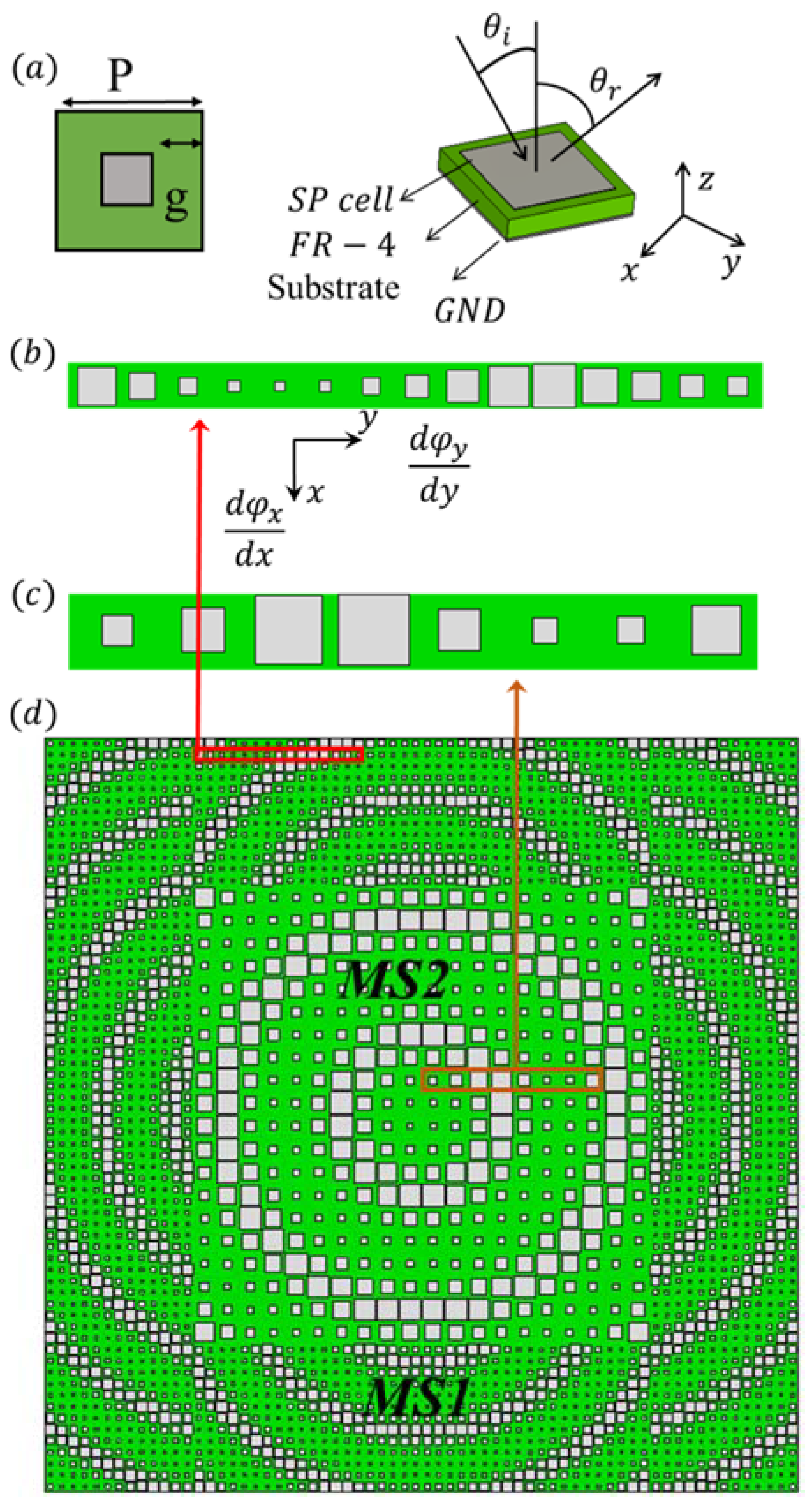
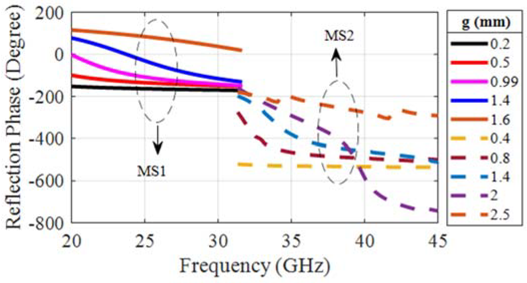
2. PGM Design
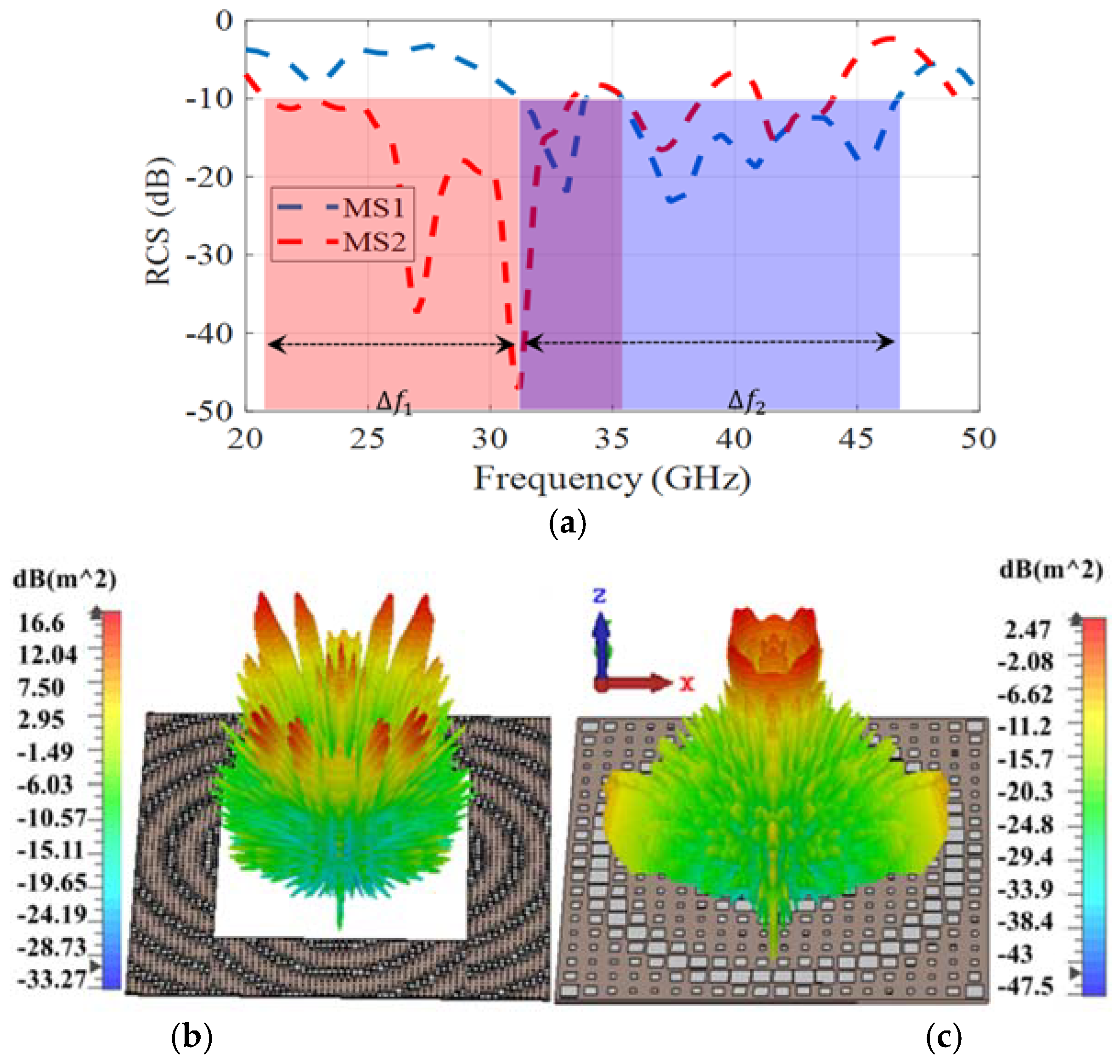
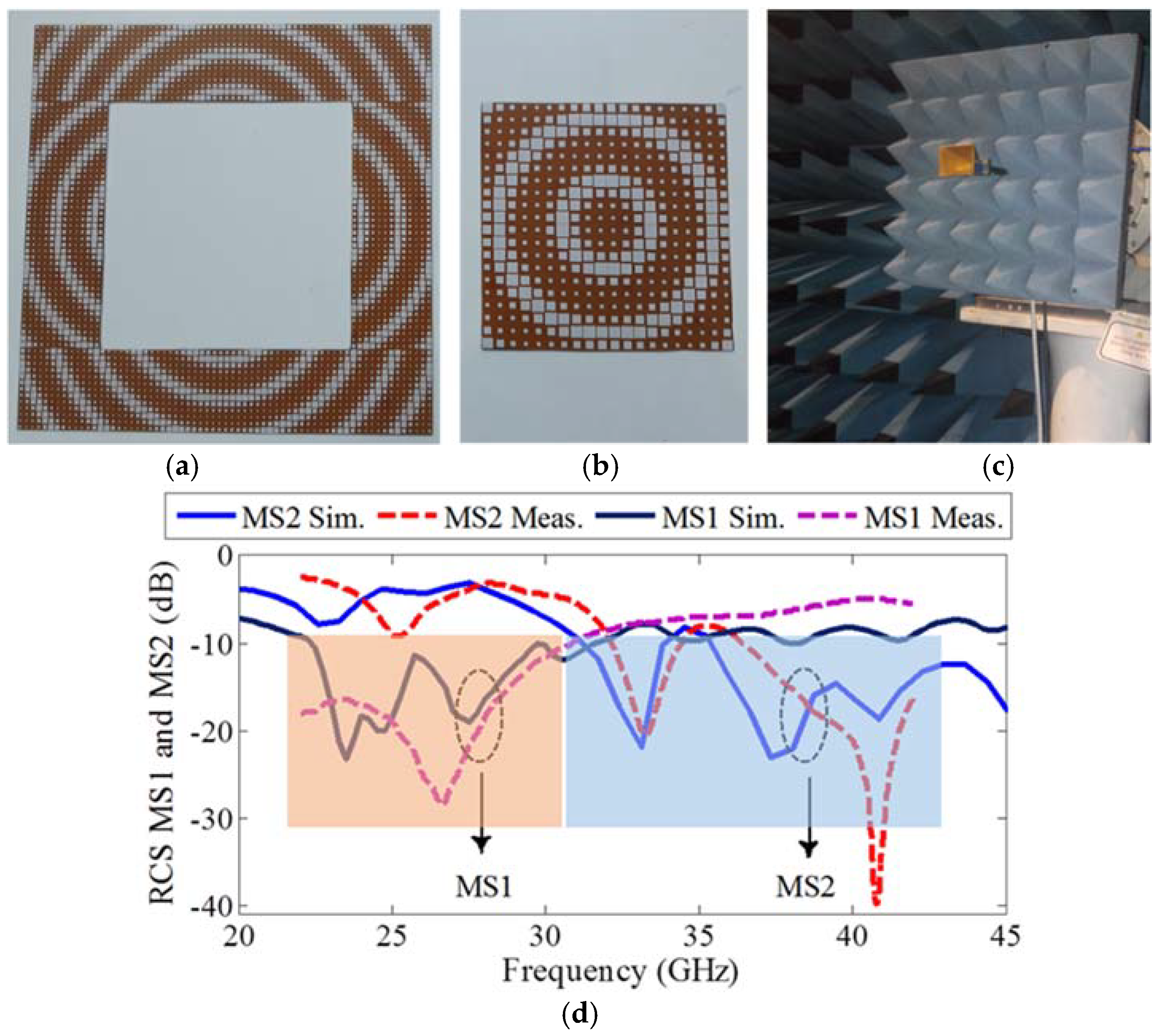
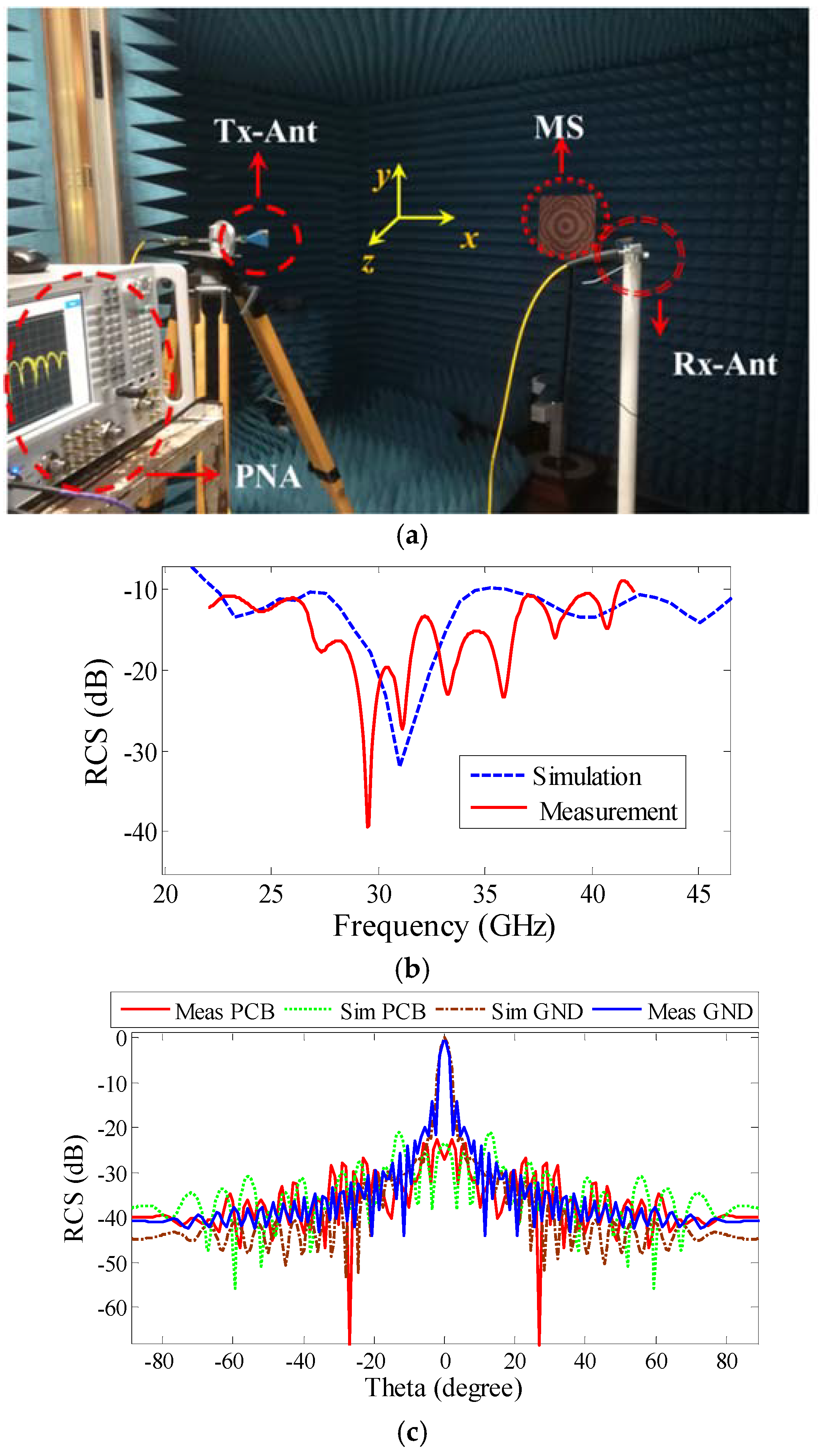
3. Measurement and Results
4. Conclusions
Author Contributions
Funding
Acknowledgments
Conflicts of Interest
References
- Esmaeli, S.; Sedighy, S. Wideband Radar Cross-Section Reduction by AMC. Electron. Lett. 2016, 52, 70–71. [Google Scholar] [CrossRef]
- Xue, J.; Jiang, W.; Gong, S. Wideband RCS Reduction of Slot-Coupled Patch Antenna by AMC Structure. Electron. Lett. 2017, 53, 1454–1456. [Google Scholar] [CrossRef]
- Chen, W.; Balanis, C.A.; Birtcher, C.R. Checkerboard EBG Surfaces for Wideband Radar Cross Section Reduction. IEEE Trans. Antennas Propag. 2015, 63, 2636–2645. [Google Scholar] [CrossRef]
- Shi, H.; Li, J.; Zhang, A.; Jiang, Y.; Wang, J.; Xu, Z.; Xia, S. Gradient Metasurface with Both Polarization-Controlled Directional Surface Wave Coupling and Anomalous Reflection. IEEE Antennas Wirel. Propag. Lett. 2015, 14, 104–107. [Google Scholar] [CrossRef]
- Li, Y.; Zhang, J.; Qu, S.; Wang, J.; Chen, H.; Xu, Z.; Zhang, A. Wideband Radar Cross Section Reduction Using Two-Dimensional Phase Gradient Metasurfaces. Appl. Phys. Lett. 2014, 104, 221110. [Google Scholar] [CrossRef]
- Zhang, W.; Liu, Y.; Gong, S.; Wang, J.; Jiang, Y. Wideband RCS Reduction of a Slot Array Antenna Using Phase Gradient Metasurface. IEEE Antennas Wirel. Propag. Lett. 2018, 17, 2193–2197. [Google Scholar] [CrossRef]
- Cheng, Y. An Ultra-Thin Dual-Band Phase-Gradient Metasurface Using Hybrid Resonant Structures for Backward RCS Reduction. Appl. Phys. A 2017, 123, 143. [Google Scholar] [CrossRef]
- Azizi, Y.; Soleimani, M.; Sedighy, S.H. Low Cost, Simple and Broad Band Radar Cross Section Reduction by Modulated and Holography Metasurfaces. J. Phys. D Appl. Phys. 2019, 52, 435003. [Google Scholar] [CrossRef]
- Liu, Y.; Hao, Y.; Li, K.; Gong, S. Wideband and Polarization-Independent Radar Cross Section Reduction Using Holographic Metasurface. IEEE Antennas Wirel. Propag. Lett. 2015, 15, 1028–1031. [Google Scholar] [CrossRef]
- Zheng, Q.; Li, Y.; Zhang, J.; Ma, H.; Wang, J.; Pang, Y.; Han, Y.; Sui, S.; Shen, Y.; Chen, H.; et al. Wideband, Wide-Angle Coding Phase Gradient Metasurfaces Based on Pancharatnam-Berry Phase. Sci. Rep. 2017, 7, srep43543. [Google Scholar] [CrossRef] [Green Version]
- Feng, M.; Li, Y.; Zheng, Q.; Zhang, J.; Han, Y.; Wang, J.; Chen, H.; Sai, S.; Ma, H.; Qu, S.; et al. Two-Dimensional Coding Phase Gradient Metasurface for RCS Reduction. J. Phys. D Appl. Phys. 2018, 51, 375103. [Google Scholar] [CrossRef]
- Saifullah, Y.; Waqas, A.B.; Yang, G.M.; Zhang, F.; Xu, F. 4-Bit Optimized Coding Metasurface for Wideband RCS Reduction. IEEE Access 2019, 7, 122378–122386. [Google Scholar] [CrossRef]
- Azizi, Y.; Soleimani, M.; Sedighy, S.H. Ultra-wideband radar cross section reduction using amplitude and phase gradient modulated surface. J. Appl. Phys. 2020, 128, 205301. [Google Scholar] [CrossRef]
- Yu, N.; Capasso, F. Flat optics with designer metasurfaces. Nat. Mater. 2014, 13, 139–150. [Google Scholar] [CrossRef] [PubMed]
- Monebhurrun, V. IEEE Standard 1502-2020: IEEE Recommended Practice for Radar Cross-Section Test Procedures [Stand on Standards]. IEEE Antennas Propag. Mag. 2021, 63, 106. [Google Scholar] [CrossRef]


| Structures | Thickness (mm) | BW (%)/ Freq. Rang (GHz) | No of Layers | Substrates |
|---|---|---|---|---|
| [1] | 2.28 | 85/9.4–23.38 | 2 | RO4003 |
| [2] | 5 | 109/6.4–21.7 | 3 | F4B/Air/F4B |
| [3] | 6.35 | 60/4.2–7.8 | 1 | RT5880 |
| [5] | 2.5 | 74/7.8–17 | 1 | FR4 |
| [6] | 3 | 82.4/7–16.8 | 1 | RO5880 |
| [7] | 0.5 | <2/8.9–11.4 | 1 | RO4350 |
| [10] | 3 | 64/9.83–19.12 | 1 | F4B |
| [11] | 3 | 46/12.1–18.8 | 1 | F4B |
| This work | 0.8 | 75/20.9–45.7 | 1 | FR4 |
Publisher’s Note: MDPI stays neutral with regard to jurisdictional claims in published maps and institutional affiliations. |
© 2021 by the authors. Licensee MDPI, Basel, Switzerland. This article is an open access article distributed under the terms and conditions of the Creative Commons Attribution (CC BY) license (https://creativecommons.org/licenses/by/4.0/).
Share and Cite
Azizi, Y.; Soleimani, M.; Sedighy, S.H.; Matekovits, L. Low-Cost, Low-Profile Wide-Band Radar Cross Section Reduction Using Dual-Concentric Phase Gradient Modulated Surface. Electronics 2021, 10, 1552. https://doi.org/10.3390/electronics10131552
Azizi Y, Soleimani M, Sedighy SH, Matekovits L. Low-Cost, Low-Profile Wide-Band Radar Cross Section Reduction Using Dual-Concentric Phase Gradient Modulated Surface. Electronics. 2021; 10(13):1552. https://doi.org/10.3390/electronics10131552
Chicago/Turabian StyleAzizi, Yousef, Mohammad Soleimani, Seyed Hasan Sedighy, and Ladislau Matekovits. 2021. "Low-Cost, Low-Profile Wide-Band Radar Cross Section Reduction Using Dual-Concentric Phase Gradient Modulated Surface" Electronics 10, no. 13: 1552. https://doi.org/10.3390/electronics10131552