Article

High-Level Renewable Energy Integrated System Frequency Control with SMES-Based Optimized Fractional Order Controller

by
Md. Shafiul Alam
1,*,
Majed A. Alotaibi
2,3,
Md Ahsanul Alam
4,
Md. Alamgir Hossain
5,
Md Shafiullah
6,
Fahad Saleh Al-Ismail
1,7,8,
Md. Mamun Ur Rashid
9 and
Mohammad A. Abido
1,8
1
K.A. CARE Energy Research and Innovation Center (ERIC), King Fahd University of Petroleum & Minerals (KFUPM), Dhahran 31261, Saudi Arabia
2
Department of Electrical Engineering, College of Engineering, King Saud University, Riyadh 11421, Saudi Arabia
3
Saudi Electricity Company Chair in Power System Reliability and Security, King Saud University, Riyadh 11421, Saudi Arabia
4
EE Department, University of Hafr Al Batin, Hafr Al Batin 39911, Saudi Arabia
5
Capability Systems Centre, School of Engineering & Information Technology, University of New South Wales-Canberra, Campbell, ACT 2612, Australia
6
Center of Research Excellence in Renewable Energy, King Fahd University of Petroleum & Minerals, Dhahran 31261, Saudi Arabia
7
Center for Environmental & Water, Research Institute, King Fahd University of Petroleum & Minerals (KFUPM), Dhahran 31261, Saudi Arabia
8
Electrical Engineering Department, King Fahd University of Petroleum & Minerals, Dhahran 31261, Saudi Arabia
9
Department of Electrical and Electronic Engineering, Bangladesh University of Engineering & Technology (BUET), Dhaka 1205, Bangladesh
*
Author to whom correspondence should be addressed.
Electronics 2021, 10(4), 511; https://doi.org/10.3390/electronics10040511
Submission received: 30 December 2020 / Revised: 6 February 2021 / Accepted: 10 February 2021 / Published: 22 February 2021

Abstract

:
The high-level penetration of renewable energy sources (RESs) is the main reason for shifting the conventional centralized power system control paradigm into distributed power system control. This massive integration of RESs faces two main problems: complex controller structure and reduced inertia. Since the system frequency stability is directly linked to the system’s total inertia, the renewable integrated system frequency control is badly affected. Thus, a fractional order controller (FOC)-based superconducting magnetic energy storage (SMES) is proposed in this work. The detailed modeling of SMES, FOC, wind, and solar systems, along with the power network, is introduced to facilitate analysis. The FOC-based SMES virtually augments the inertia to stabilize the system frequency in generation and load mismatches. Since the tuning of FOC and SMES controller parameters is challenging due to nonlinearities, the whale optimization algorithm (WOA) is used to optimize the parameters. The optimized FOC-based SMES is tested under fluctuating wind and solar powers. The extensive simulations are carried out using MATLAB Simulink environment considering different scenarios, such as light and high load profile variations, multiple load profile variations, and reduced system inertia. It is observed that the proposed FOC-based SMES improves several performance indices, such as settling time, overshoot, undershoot compared to the conventional technique.

1. Introduction

Environmental concern and increasing energy demand lead to an extensive penetration of renewable energy sources (RESs) into distribution networks that force to reshape power systems where conventional fossil-fuel-based power plants are being replaced by RES rapidly. These RESs, being pollution-free, cheap, and conforming to the concept of sustainable development, gained considerable attention worldwide in the last two decades. Many countries have effectively integrated a large share of RES into the primary grid, and a high penetration level is targeted for the next three decades. For example, China targets 69%, whereas that for EU 74%, India 75%, and USA 63% from RES by the year 2050 [1].

1.1. Issues with Frequency Deviation

The most promising RESs are the solar and wind power generations are due to the available resources, lower cost of power generation, and maximum power point tracking capability over a wide range of wind and sunlight variation [2,3]. The inherent volatility and uncertainty characteristics with these resources, these sources are generally connected via power electronics-based inverter/converters to the power network. Their interaction with the grid is substantially different from that of the conventional synchronous generator (SG)-based plants that use steam and hydro turbines. While intrinsic kinetic energy in the SG rotor inherently provides inertia to the system, this is not the case for the RES connected via power electronics converters. Consequently, during disturbances and supply/demand imbalances, the inertia, which slows down the natural reaction of the system and provides time for the responsible controllers to take actions, is significantly reduced because the rate of change of frequency (RoCoF) is much higher in systems with low inertia [4]. This high level of RoCoF and large frequency deviation (Δf) can provoke the tripping of sensible loads, generating units and relays, thus affecting system frequency stability even at small load-generation mismatch [5,6]. Although the variable wind turbines have inertia, they are effectively decoupled from the system due to the power electronics-based converter interface; thus, it cannot improve frequency response.
Similarly, solar PV plants also do not have any rotating parts, thus cannot provide any inertia to the power system. As a result, the high-level integration of RESs reduces the system’s total inertia due to the replacement of conventional synchronous generators. Moreover, the reduction in reserve power due to the replacement of reserve generating units causes frequency deviation [7]. With the RES level increase, the power oscillations and frequency stability issues increase under disturbances [8], which may set the critical limit for RES share [9]. To promote ambitious RES penetration levels in the grid, some form of mitigation scheme is required, and this has received significant attention from the researchers.

1.2. Mitigation Schemes

To address the frequency excursion issues with the low inertia system, several techniques are presented in the literature, such as auxiliary load frequency control (LFC) technique, inertia emulation technique, deloading technique, droop technique, and energy storage-based techniques [10,11,12]. Among these, LFC is most extensively used for several decades to meet two main objectives: maintaining the system frequency and tie-line power deviation within specified values [13]. Because of fluctuating active power generation, integration of wind/PV system makes load frequency control more challenging. The incorporation of the energy storage system (ESS) in the LFC loop demonstrated a useful technique for enhancing frequency stability [13,14,15]. With proper control, additional inertia can be imitated for frequency stability and resiliency [16,17]. Among the various ESS studied, such as superconducting magnetic energy storage (SMES), supercapacitors, electric batteries, fuel cell, flywheel energy storage, SMES technology is recognized as the best candidate for inertia emulation [18,19,20].
Performance of emulated inertia and LFC system vastly depends on the control technique employed. Recently, various control techniques have been suggested for the LFC of the RES integrated power system. In [21], frequency control of the interconnected power system, including wind farms, is presented where the symbiotic organism search algorithm optimized PID parameters. However, in this study, no energy storage system is considered. In [22], a model predictive control (MPC)-based synthetic inertial control is proposed for a wind farm consisting of wind turbines (WTs) and a battery storage energy system (BESS). In [23], battery energy storage is used for frequency support of a doubly fed induction generator (DFIG)-based wind system. The battery is connected to the DC link of DFIG and controlled with the droop technique to reduce frequency deviation by scheduling active power exchange during system disturbances. In [24], supercapacitor energy storage system is proposed to emulate the dynamic inertia response of PV-based ac microgrid cluster. The detailed design of feedback and proportion gains; however, are not discussed in this work.
In [25], an auxiliary LFC technique is presented to control the frequency of the Egyptian grid considering high-level PV and wind integration employing a proportional-integral-derivative (PID) controller. However, the LFC technique does not consider the detailed Egyptian grid model; also, it excludes tie-line power that needs further investigation. In [26], a virtual inertia support technique is presented for low inertia microgrid with particle swarm optimization (PSO)-based PI controller. In [14], SMES-based virtual inertia control is proposed for a microgrid system. The conventional derivative approach virtual inertia control loop is implemented. The detailed design of feedback and proportion gains; however, are not discussed in this work. In [27], a self-adaptive virtual inertia fuzzy controller is adopted for the high-level renewable integrated system. The proportional virtual gain is adapted by the fuzzy system, which uses the deviation of real power and frequency as inputs. In this scheme; however, the generalized energy storage is considered by a simple 1st order system. The sharing of active power from different energy storages are scheduled based on their capabilities in [28] for frequency control of renewable sources. In this capability coordinated frequency control (CCFC) approach, the total error signal is forwarded to the primary control loop of each unit based on their capabilities. The LFC for mass-less inertia PV systems is presented in [29] with PI controllers. The parameters are optimized with the PSO-WOA hybrid optimization technique in case of different step load changes. To stabilize a low inertia PV system, another virtual inertia synthetization of synchroconverter is reported in [30] with a machine learning technique. The optimized virtual inertia frequency control and protection schemes are developed in [31,32] for low frequency interconnected power systems. A combined SMES and thyristor controlled phase shifters (TCPS) [33] are applied in low inertia utility grid with an adaptive neuro-fuzzy inference system (ANFIS) controller. The detailed design of SMES negative feedback and proportional gains, however, is not considered.

1.3. Research Gaps and Contributions

In recent years, fractional calculus gained popularity and is recognized as a powerful tool in the control engineering field. It is proved that the fractional order approach can provide better overall closed-loop system performance than the integer order control [34]. This is attributed to the possibility of a more robust tuning of fractional order controller (FOC) in the presence of additional real parameters [35,36]. Analytic, numerical, rule-based, and self-tuning and auto-tuning methods are commonly used for tuning fractional order PI/PID controllers [37]. For superior performance, different optimization methods have been proposed in the past like—genetic algorithm (GA) [38], adaptive genetic algorithm (AGA) [39], particle swarm optimization (PSO) [39], modified PSO (MPSO) [40], differential evolution (DE) [41], electromagnetic-like (EM) algorithm [41], non-dominated sorting genetic algorithm (NSGA) [42], artificial bee colony (ABC) algorithm [43], seeker optimization algorithm (SOA) [44], harmony search (HS) algorithm [45], Tabu Search (TS) algorithm [46]. Each method employs the objective function of varying degrees of complexity and has a different convergence speed.
Based on the above critical review of several recent works, especially the works focusing on SMES or other energy storage applications in low inertia system, it is identified that the detailed design of SMES is missing with FOC to support virtual inertia for RESs. The integer order controller is not adequate to control the dynamic behavior of the power system integrating large-scale RESs. Thus, in this work, we propose an optimal design approach for the fractional order PI controller and SMES. The dynamic model of the system with SMES and fractional order PI controller is introduced, and parameters are tuned with the WOA algorithm based on frequency deviation cost function. The WOA has several advantages that make it attractive for its applicability to a wide range of optimization problems [47]. Among these are (1) WOA is a gradient-free method, like many other population-based algorithms. This eliminates the calculation of the gradient and step-size at each iteration of the optimization process; (2) the WOA has inherent adaptive exploration and exploitation mechanism which reduces the probability of getting trapped in local solution; (3) it is insensitive to the initial solution(s), which may significantly affect the convergence and performance of the traditional methods; (4) it is easy to implement and flexible. To the best of the authors’ knowledge, the main contribution of the proposed optimized FOC-based SMES controller in RESs integrated system can be summarized as below.
  • The inertia of the system is supported virtually, which makes the system stable over a wide range of load-generation mismatch.
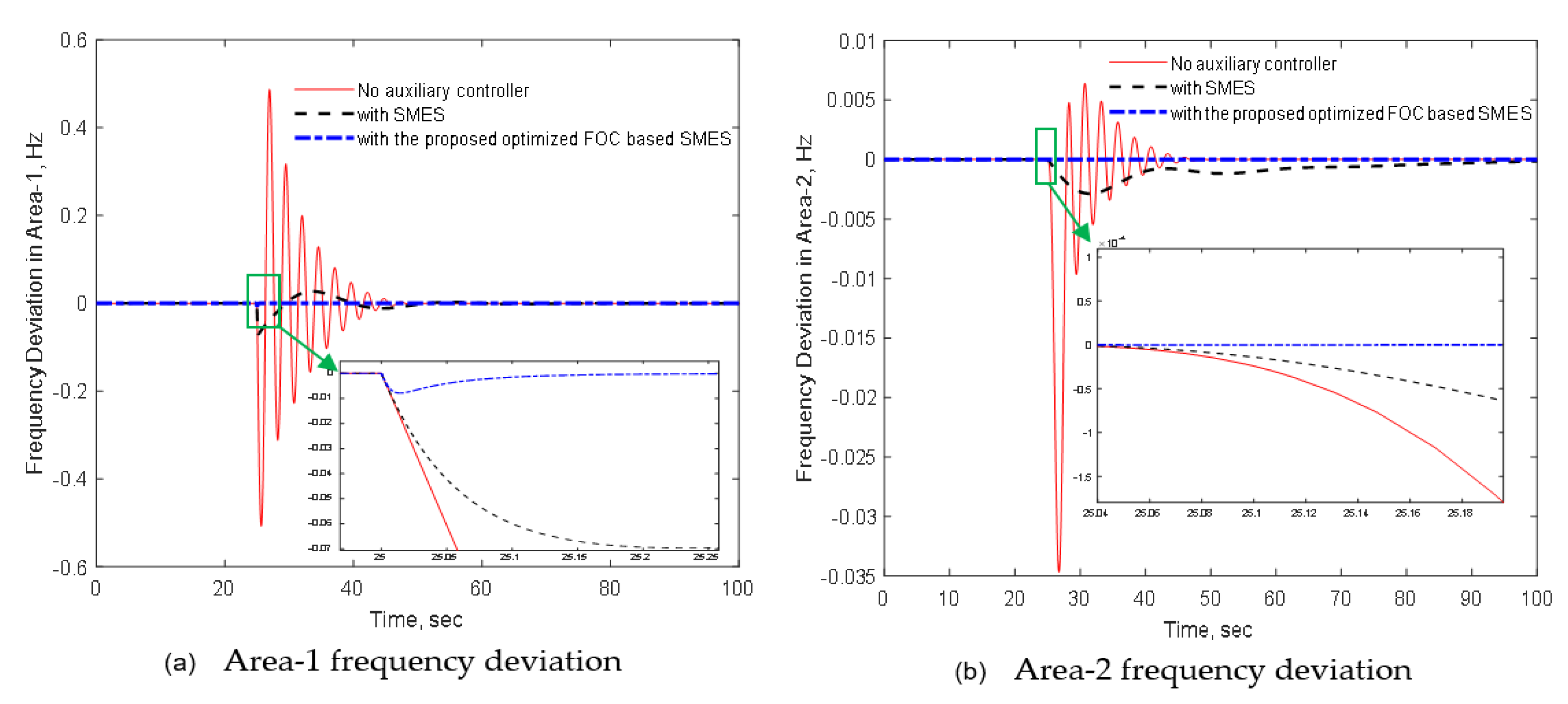
  • The system frequency deviation is greatly improved with the proposed approach.
  • The proposed optimized FOC-based SMES approach is robust against system parameter variations.
  • The overshoot, undershoot, and settling time of the response are improved compared to the conventional approach.
  • The proposed approach endorses the green effort to augment sustainability.
The rest of the paper is organized as follows. Section 2 describes the dynamic model of the PV/wind integrated system to facilitate analysis. The detailed modeling of SMES and the proposed controller design technique are presented in Section 3. The simulated results and discussions are presented in Section 4 with several scenarios. Finally, the outcomes and contributions of this work are summarized in Section 5.

2. Renewable Energy Integrated System Modeling

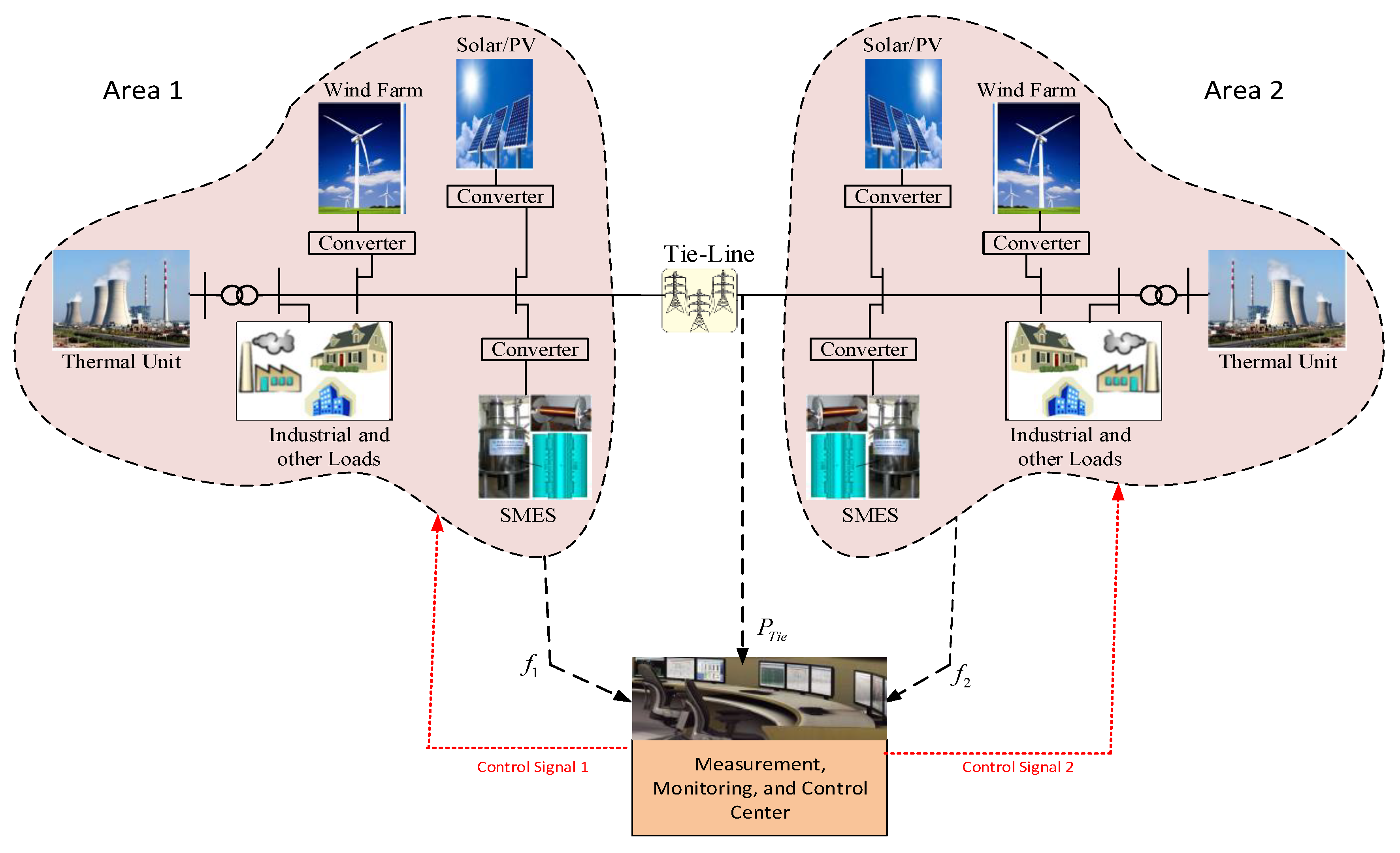
2.1. System Configuration

A two area of wind/PV integrated hybrid power system, as shown in Figure 1, is considered for the frequency control study. Each area comprises the conventional thermal generating unit, solar PV, industrial load, and superconducting magnetic energy storage (SMES). The fractional order PI controller is designed for the SMES to virtually support inertia, thereby mitigating the high-frequency excursion problem caused by generation load mismatch. As mentioned earlier, this low system inertia is a consequence of high-level renewable energy penetration. A tie-line interconnects these two areas. Measured frequency deviation and tie-line power signals are accumulated in the control and monitoring center, and then it sends appropriate control signals to the controllable SMES of both areas.

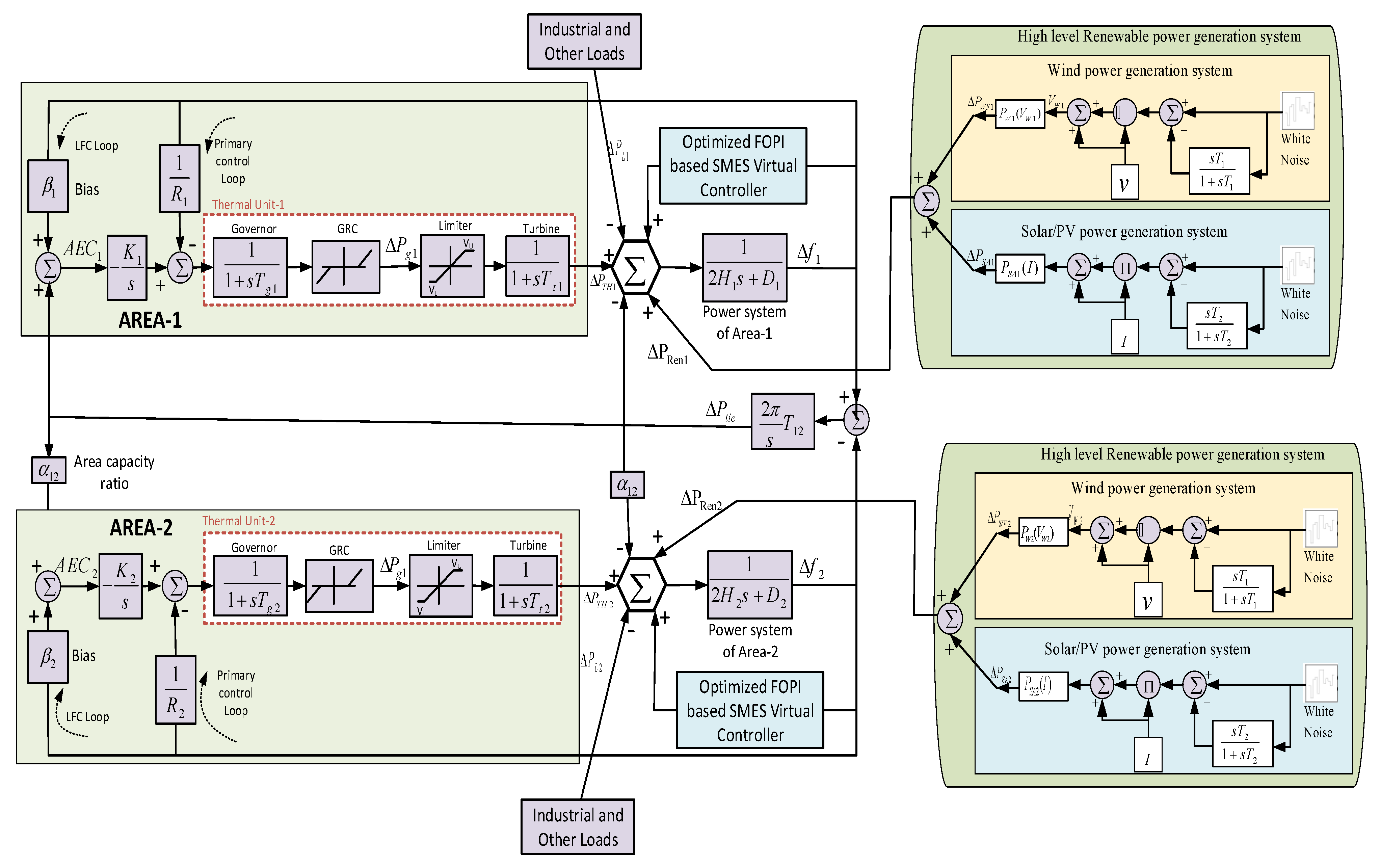
2.2. System Dynamic Modeling

To analyze frequency control in the presence of RESs, adequate dynamic model of the studied system is constructed. For precise demonstration of the dynamic behavior of interconnected system, generally higher order nonlinear models for thermal generating units, wind system, solar PV, converters are considered. For large power system with power electronic converters, however, the simplified dynamic models are employed to study the frequency stability. The interested readers can find more details on such dynamic modeling in [14,48]. For frequency stability analysis, the simplified dynamic model of the two area system can be developed as shown in Figure 2.
As the RESs generate energy from intermittent natural resources, the output power generated by them is variable. To reflect the realistic power output of fluctuating profile, white noise is added to the wind and PV system model, as shown in Figure 2.
For a wind turbine (WT) with a given physical dimension, the power output (PWT) mainly depends on wind velocity (Vw), which is variable. In this model, the wind-speed is multiplied by the random speed fluctuation (white noise) to estimate the WT output power fluctuations (ΔPWT).
Similarly, a PV system harvests energy from solar irradiation. For a given solar panel, the output power (Ppv) mainly depends on the solar irradiation (I) and atmospheric temperature (T). Like WT, solar irradiation (I) is multiplied by the white noise to estimate PV output power fluctuations (ΔPpv).
Usually, renewable power plants deliver a considerable amount of power to the system without taking part in frequency control. Thus, solar PV, wind, and different loads (e.g., residential and industrial) are modeled as disturbances in the dynamic model. For further details on dynamic models of wind/PV systems, interested readers are directed to the literature [48].
In an interconnected power system, several physical constraints, such as generation rate constraints (GRC) and generator dead band (GDB), introduce nonlinearity and influence dynamic responses [49]. It is shown that the dynamic responses of the system experience larger overshoot and longer settling times of frequency and tie-line power oscillation when these constraints are considered. Thus, controllers designed without considering these constraints may not perform well in practical application and even may lead to instability. Therefore, both constraints, GRC and GDB, are taken into consideration in these studies to reflect the practical implementation case.
As shown in Figure 2, the frequency deviation dynamics of the k-th area can be written as follows.
Δ f k = 1 2 H k S + D k ( Δ P T H , k + Δ P S A , k + Δ P W F , k Δ P L , k + Δ P t i e , k ± Δ P S M E S , k )
where
Δ P T H , k = 1 1 + s T t , k ( Δ P g , k )
Δ P g , k = 1 1 + s T g , k ( Δ P A E C , k 1 R k Δ f k )
Δ P W F , k = 1 1 + s T w i n d , k ( Δ P w i n d , k )
Δ P S A , k = 1 1 + s T p v , k ( Δ P p v , k )
where H k , and D k are the inertia constant, and damping constant respectively in area-k. Δ P T H , k , Δ P S A , k , and Δ P W F , k are the incremental power of thermal unit, solar farm, and wind farm, respectively, in area-k. T t , k , T g , k , T w i n d , k , and T p v , k are the time constant of turbine, governor, wind turbine, and solar PV, respectively, in area-k. Δ P S M E S , k is the variation in power output of the SMES. While conventional power generation block adjusts its power output depending on the change in frequency, the SMES block exchange (injects/absorbs) power with the grid that depends on system frequency deviation.

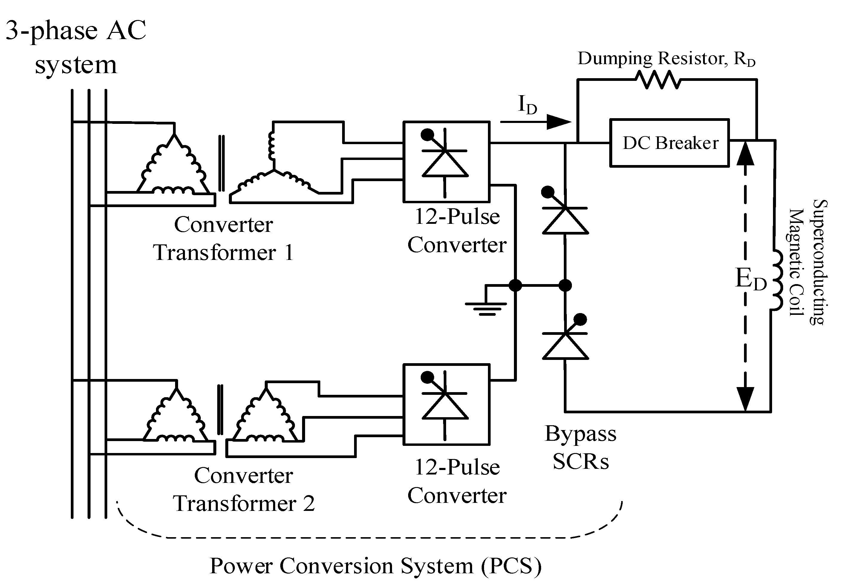
3. SMES Model with FOC

The superconducting magnetic energy storage (SMES) devices are capable of exchanging huge amount of power within very short duration. Its unique features, such as fast response, high efficiency, and long lifetime, have drawn the attention to the researchers in power system application and regarded as a very promising device for power system dynamic stability enhancement.
The SMES consists of two main parts: (i) the superconducting coil which is kept under extremely low temperature, and (ii) the power conversion system (PCS)—consisting of inverter/rectifier circuits [33]. The energy exchange between the superconducting coil and the AC grid is facilitated by the three-phase transformers as shown in Figure 3. Two cascaded 12-pulse bridges filter the harmonic contents of the signals.
During normal steady-state operating condition of the power system, the SMES coil is charged from the grid to its present value within very short period of time. In its charged state, the SMES coil starts conducting DC current with nearly zero losses as the coil temperature is maintained at extremely low value. The resulting DC voltage across the inductor is given by [14]
E D = 2 V d o cos α 2 I D R D
where V d 0 is the maximum voltage of the bridge circuit, α is the thyristor firing angle, I D is the superconducting coil current, and R D is the commutating resistance or damping resistor. Thus, DC voltage appearing across the superconducting coil can be controlled with the variation of firing angle, α . When the α is greater than 90°, the energy stored in the superconducting coil is released to the grid. Whereas, superconducting coil charges if the α is below 90°. In this way, inversion and rectification mode of converter discharges and charges, respectively, the superconducting coil almost instantly. It is also worth mentioning that the current through the coil has always positive direction, only altering voltage, either negative or positive, across the coil initiates the inversion or rectification mode.
Now, during contingencies, as the power demand is initiated by the power system, the SMES discharges the stored energy through the PCS to the grid almost instantly, even before the governor and other supplementary control units start acting. After the contingencies, while the governors start working to support the power demand, the SMES again starts charging its preset value.
The detailed dynamic model of SMES for frequency stability studies along with the fractional order PI controller is shown in Figure 4. During excessive system loading, load surpasses the generation, the E D becomes negative while the current I D maintains the same direction. The incremental change in E D can be written as
Δ E D = K S M E S Δ E K I D Δ I D 1 + s T D C
where K S M E S is the SMES gain, Δ E is the output of fractional order PI controller, K I D is the negative feedback gain, Δ I D is the incremental change in superconducting coil current, T D C is the converter delay time. The incremental change in inductor current I D is written as
Δ I D = Δ E D s L
The active power deviation of SMES is given by
Δ P S M E S = Δ E D ( I D 0 + Δ I D )

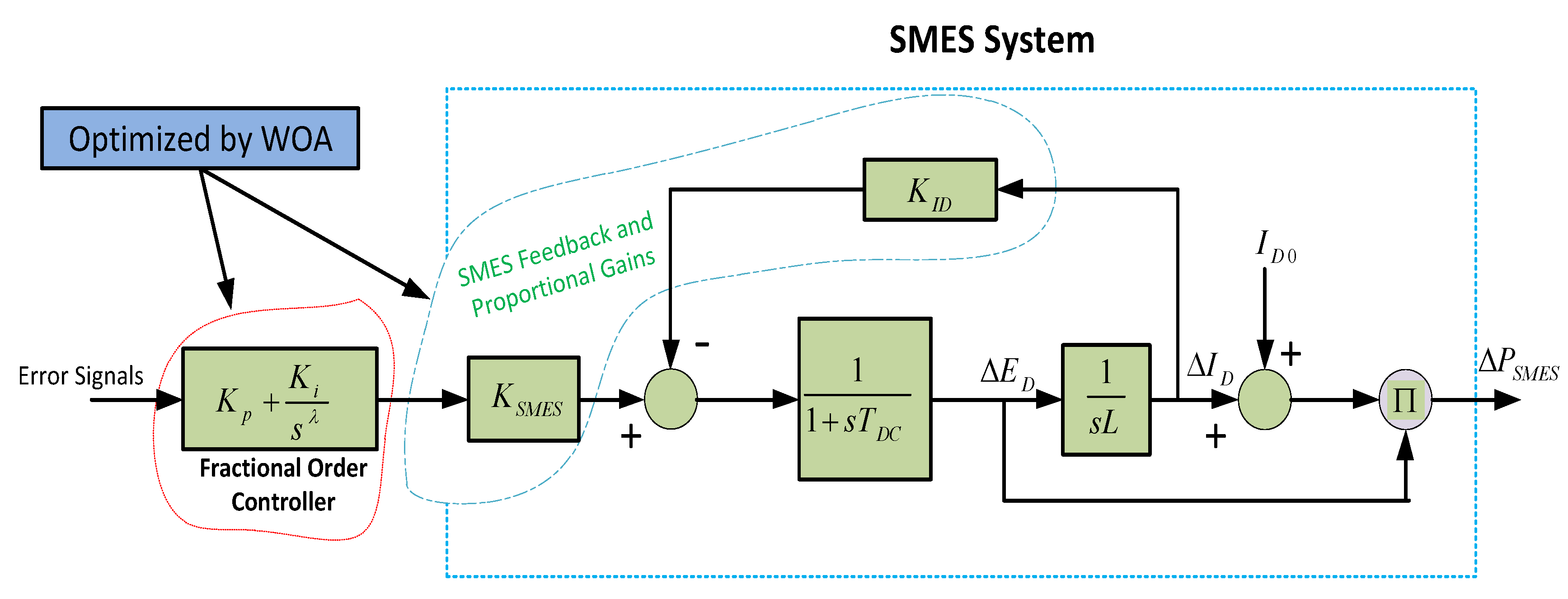
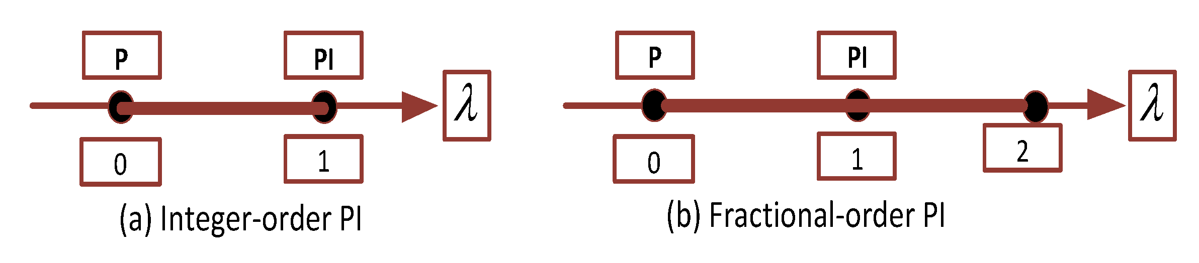
3.1. Fractional Order PI-Based SMES Controller Design

Fractional order PI-based SMES controller is proposed to improve frequency stability of low inertia power system considered in this study. The fractional order calculus involves generalized integration and differentiation of non-integer order, and these mathematical phenomena allow describing a real system more precisely than the classical integer order methods, especially when the dynamic system is of distributed parameter nature [50,51]. As the fractional order controllers tuning is reaching to a matured state of practical use, their domination in the industry is increasing rapidly due to superior performance over conventional integer order controller.
The time domain fractional order PI controller can be represented as
u ( t ) = K p e ( t ) + t λ K i e ( t ) d t
where e ( t ) is the error signal, K p is the proportional gain, K i is the integral gain, λ is the fractional order and a real number which lies between 0 to 2. The Laplace transformation gives the following transfer function for the fractional order PI controller.
C ( s ) = K p + K i S λ , λ ( 0 , 2 )
The conventional integer order PI and fractional order PI can be understood by Figure 5 in λ axis. The integer order controller is represented by two fixed points on the λ axis. Whereas, the fractional order PI controller can be represented by infinite number of points between 0 and 2. Thus, it gives more degree of freedom and flexibility over the conventional integer order controller.
As presented in Figure 4, the SMES virtual inertia based on fractional order PI is developed in this study to support the frequency of the low inertia interconnected system. WOA optimizes the feedback and proportional gains of SMES and the fractional order PI’s proportional gain, integral gain, and fractional parameter. The following subsections describe the formulation of objective function and solution method employing WOA.

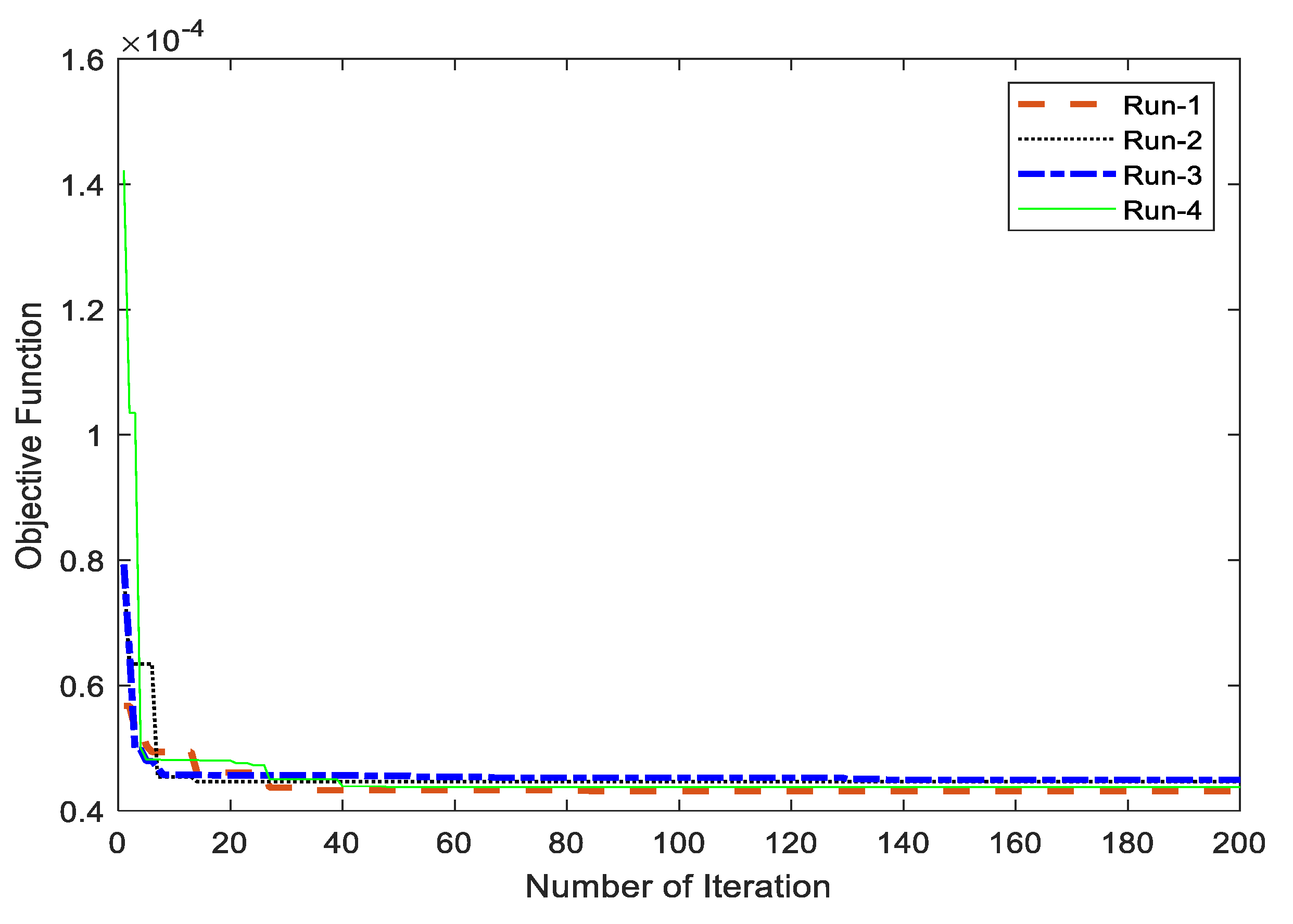
3.2. Description of the Cost Function

The appropriate cost function is vital in the application of nature inspired and heuristic optimization techniques in power system. In general, the cost function is defined to minimize the several performance indices like overshoot, undershoot, and settling time for various signals. In this work, several fractional order PI gains, fractional orders, SMES feedback gains, and proportional gains are designed based on the area frequency deviation and tie-line power fluctuation cost function. For the better comprehension of the optimization process, the following cost function, decision variables, and constraints are considered.
Minimize:
I S E = 0 T ( | Δ f 1 | 2 + | Δ f 2 | 2 + | Δ P t i e | 2 ) d t
Decision Variables:
K p 1 ,   K i 1 ,   λ 1 ,   K p 2 ,   K i 2 ,   λ 2 ,   K 1 ,   K 2 ,   K I D 1 ,   K S M E S 1 ,   K I D 2 ,   K S M E S 2
Constraints:
K p 1 m i n < K p 1 < K p 1 m a x ,   K i 1 m i n < K i 1 < K i 1 m a x ,   λ 1 m i n < λ 1 < λ 1 m a x , K p 2 m i n < K p 2 < K p 2 m a x ,   K i 2 m i n < K i 2 < K i 2 m a x , λ 2 m i n < λ 2 < λ 2 m a x ,   K 1 m i n < K 1 < K 1 m a x ,   K 2 m i n < K 2 < K 2 m a x ,   K I D 1 m i n < K I D 1 < K I D 1 m a x ,   K S M E S 1 m i n < K S M E S 1 < K S M E S 1 m a x ,   K I D 2 m i n < K I D 2 < K I D 2 m a x ,   K S M E S 2 m i n < K S M E S 2 < K S M E S 2 m a x
where subscripts 1 and 2 are to denote area-1 and area-2 for the interconnected power system. T is the simulation time, Δ f is the frequency deviation, Δ P t i e is the tie-line power deviation. K p is the fractional order PI proportional gain, K i is the FOC integral gain, K 1 & K 2 are the Area Error Controller (ACE) integral gains, K I D is the SMES negative feedback gain, and K S M E S is the SMES proportional gain. Mainly, the upper and lower limits of the equation 14 are selected based on knowledge/experience of FOC and SMES applications in power system. The optimization algorithm is coded in MATLAB script (.m file) environment and linked with the MATLAB Simulink (.slx files) environment.

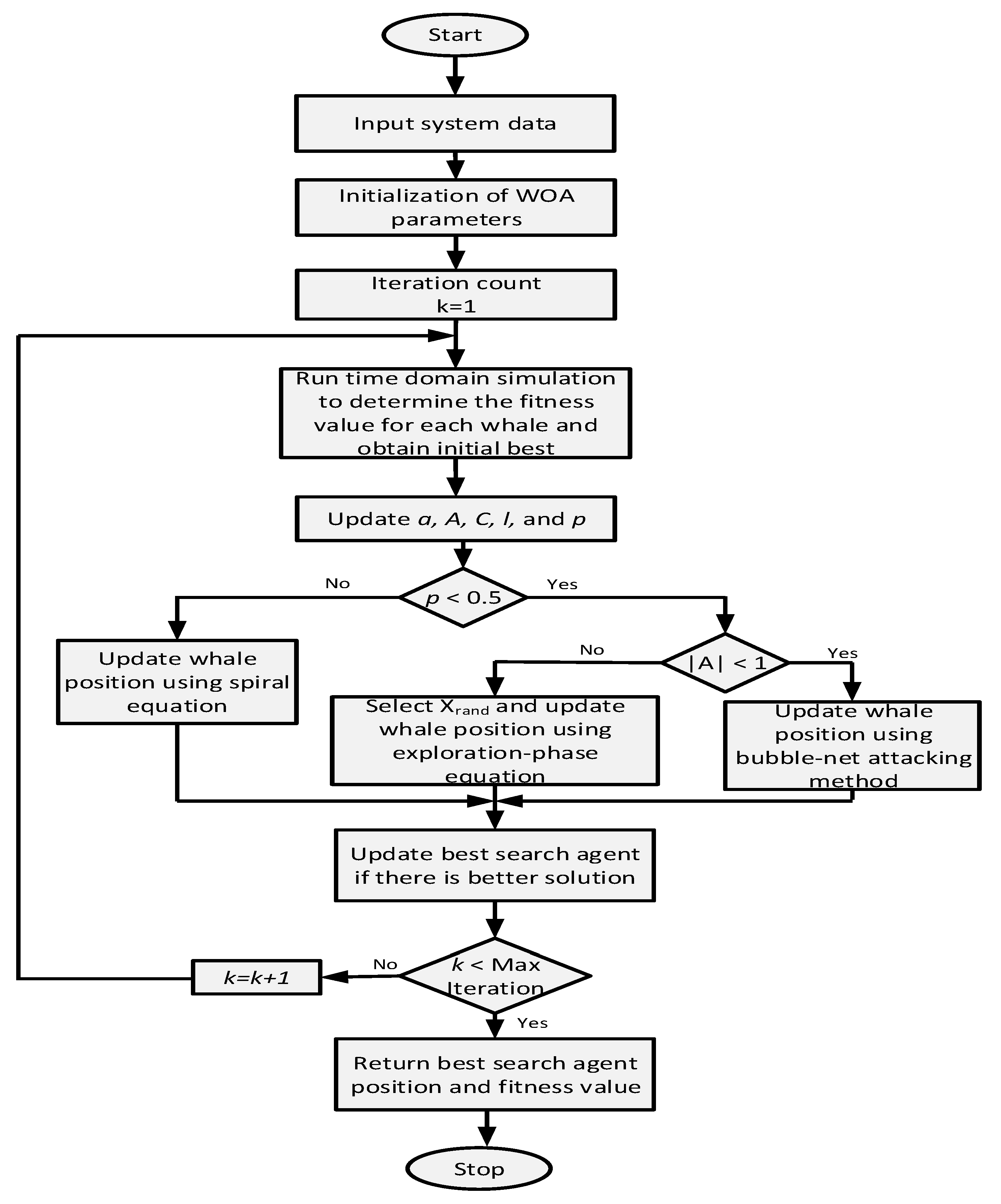
3.3. Controller Design with WOA

The minimization problem described by equation 12 is solved by whale optimization algorithm (WOA). Because of its inherent adaptive exploration and exploitation capability, WOA outperforms state-of-the-art metaheuristic algorithms, e.g., PSO, GA, GSA, ACO. Recently, WOA is being applied in many large-scale and real-world engineering optimization problems [47,52].
WOA is a metaheuristic algorithm that mimics the unique hunting strategy of humpback whales. The whale searches for the prey (e.g., krill, small fishes), and then attacks them by a technique called bubble-net hunting. Entire hunting mechanism consists of three processes, (i) encircling prey (ii) bubble-net feeding method, and (iii) search for prey. These processes are mathematically modeled in WOA as described below [53].
a. 
Encircling prey
Upon locating the prey, the humpback whale encircles them and advances their position toward the best search agent. During the course of iteration this behavior is expressed mathematically as
D = [ C · X * ( k ) X ( k ) ]
X ( k + 1 ) = X * ( k ) A · D
where k is the current iteration, X is the current position vector, X * is the best position of the solution obtained so far. A and C are coefficient vectors which are updated as follows
A = 2 a · r a
C = 2 · r
where r is a random vector in [0, 1], and a is linearly decreased from 2 to 0 over the course of iterations. a is updated as a ( k ) = 2 ( 1 k / I max ) , where Imax is the maximum number of iterations.
b. 
Bubble-net attacking mechanism
In this phase, the humpback whale starts to push bubbles and move toward the prey by shrinking circle and spiral-shaped path. The position of the humpback whale and the prey to mimic the helix-shaped motion is given by
X ( k + 1 ) = D · e b l · cos ( 2 Π l ) + X * ( k )
with
D = | X * ( k ) X ( k ) |
where l is a random number in [−1,1], and b is a constant defining spiral-shaped motion.
A probability p of 0.5 is assumed to distinguish between bubbles attacking with shrinking behavior and spiral motions as given by
X ( k + 1 ) = { X * ( k ) A · D if   p < 0.5 D · e b l · cos ( 2 Π l ) + X * ( k ) if   p 0.5
where p is a random number in [0, 1].
c. 
Search for prey
To increase the diversity of solutions and achieve a global solution, the search space is extended by using | A | > 1 . Thus, in prey search phase, the humpback whales are forced to move away from a random whale position. The representative equation for the prey search is given by
D = [ C · X r a n d X ( k ) ]
X ( k + 1 ) = X r a n d A · D
where X r a n d is the position of a whale selected randomly from the current population.
The overall flow chart for the WOA to design fractional order PI and SMES parameters is shown in Figure 6.

4. Simulation Results and Discussion

4.1. Simulation Results

The effectiveness and robustness of the proposed optimized FOC-based SMES to improve the frequency stability are presented in this section. The system modeled in Section 2 is considered for analytical analysis. The system parameters and optimized controller parameters listed in Table 1 and Table 2, respectively, are used to conduct time domain simulations and facilitate analysis. The MATLAB Simulink is used to conduct analyses considering different scenarios such as light loading, heavy loading, solar and wind power variations, and reduced inertia. The frequency deviations in both areas are plotted to show the effectiveness of the proposed FOC. The system dynamic model and optimization code are interlinked to find the optimized parameters. The convergence of the optimization algorithm depicted in Figure 7 shows that most of the runs in simulation converge before 30 iterations.

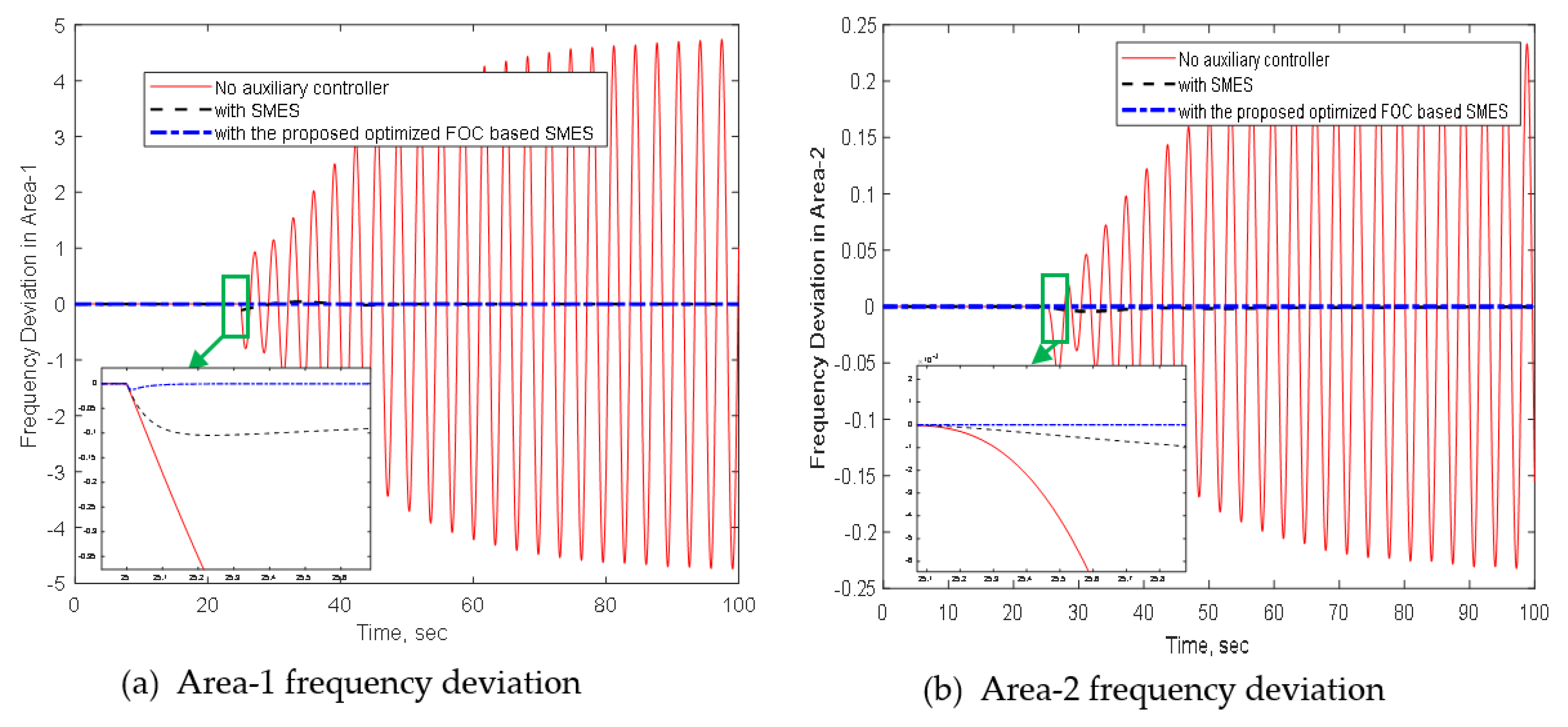
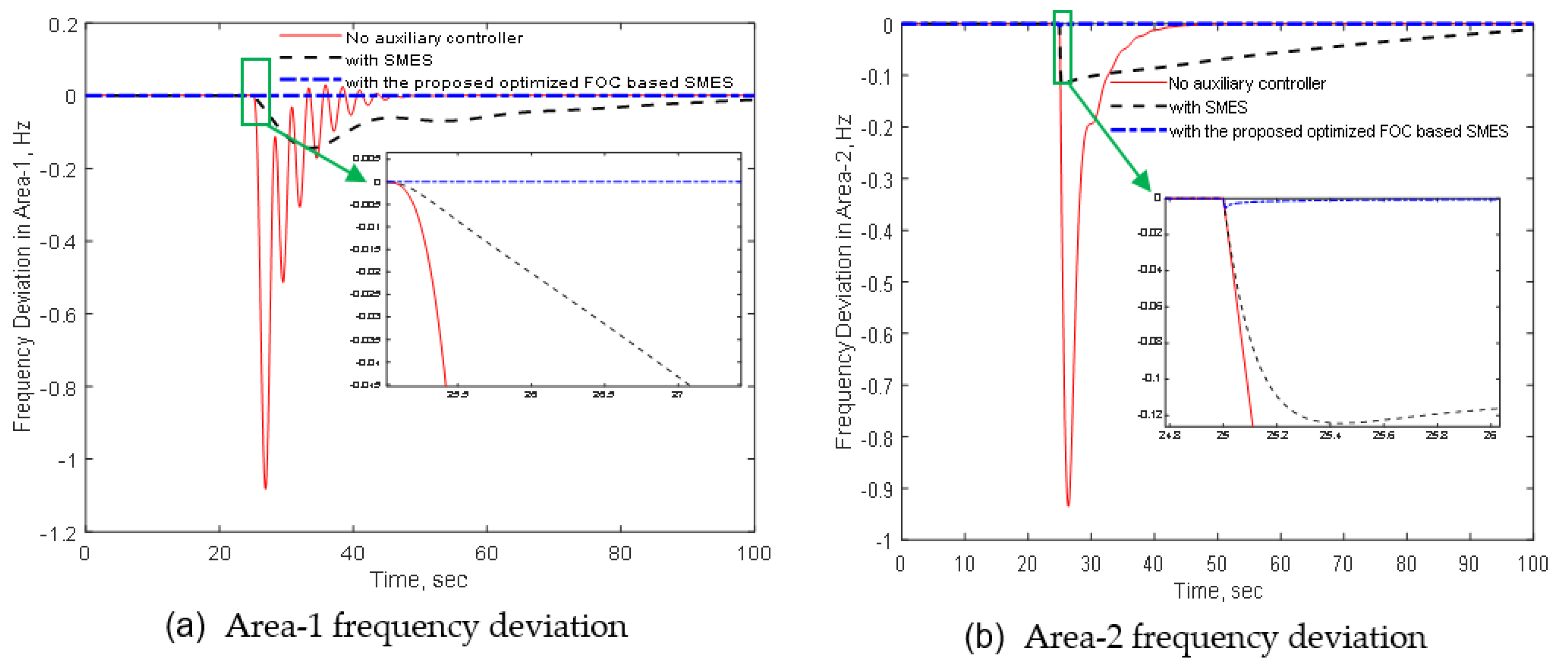
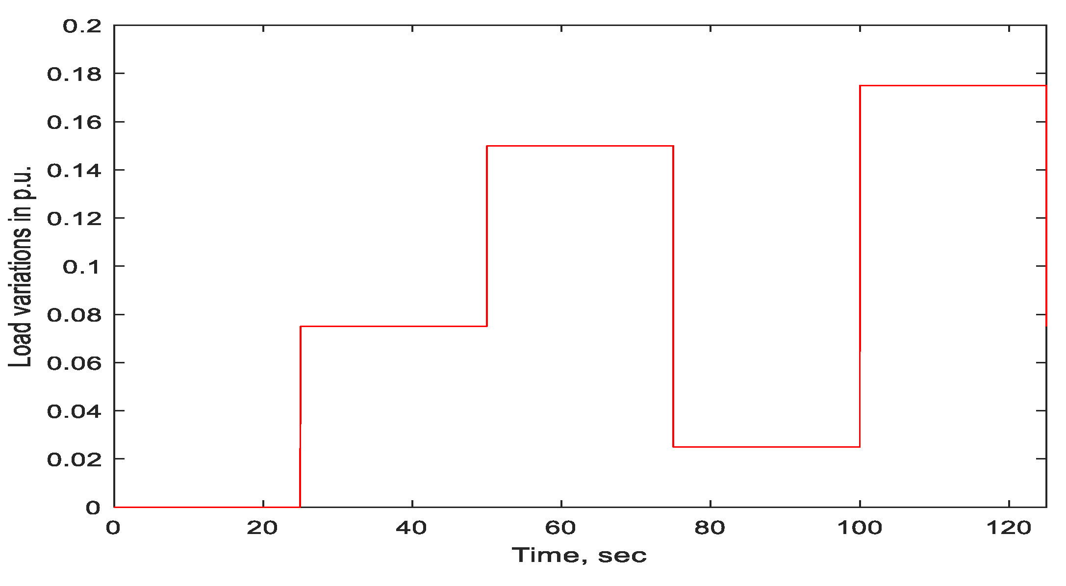
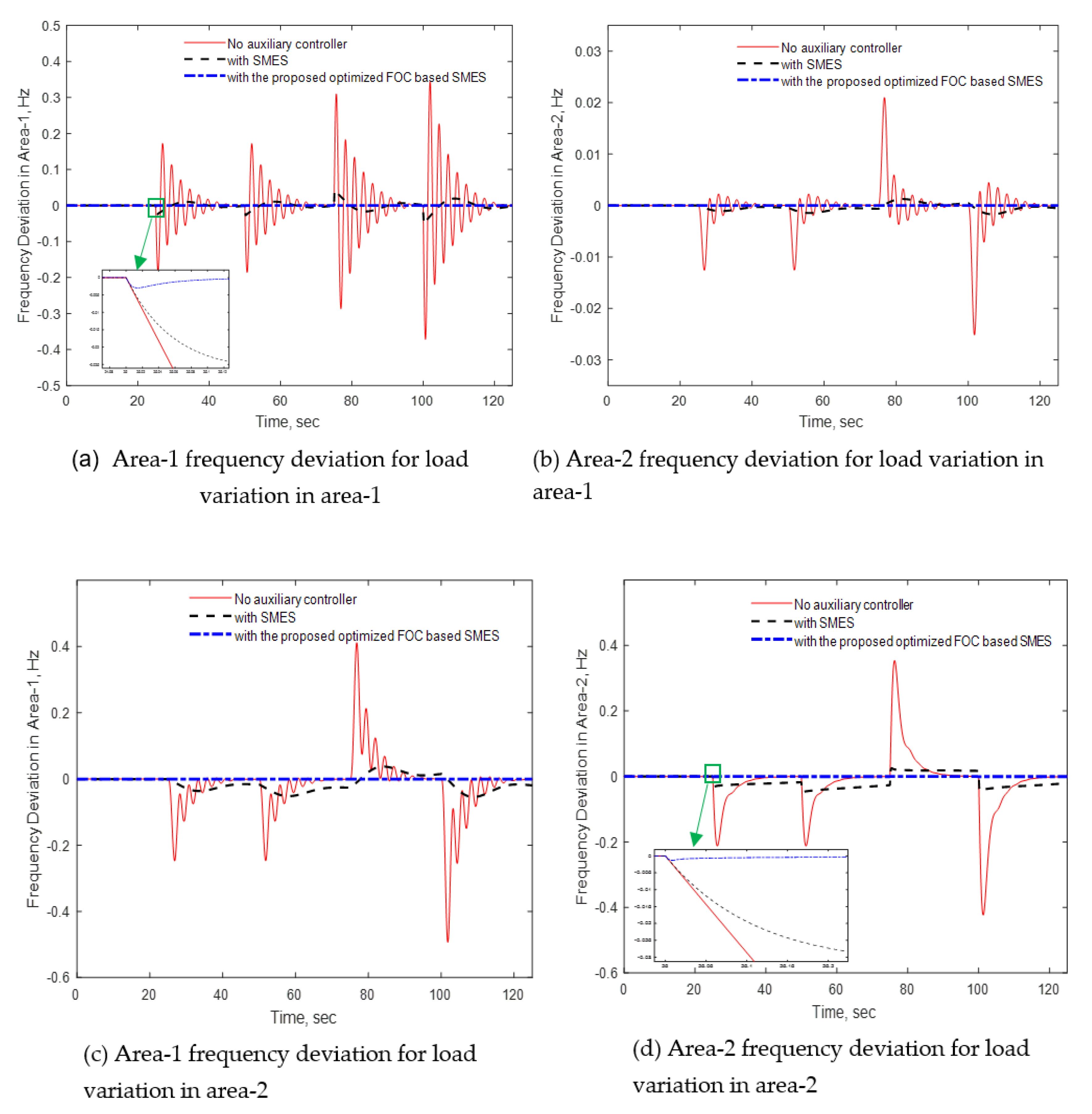
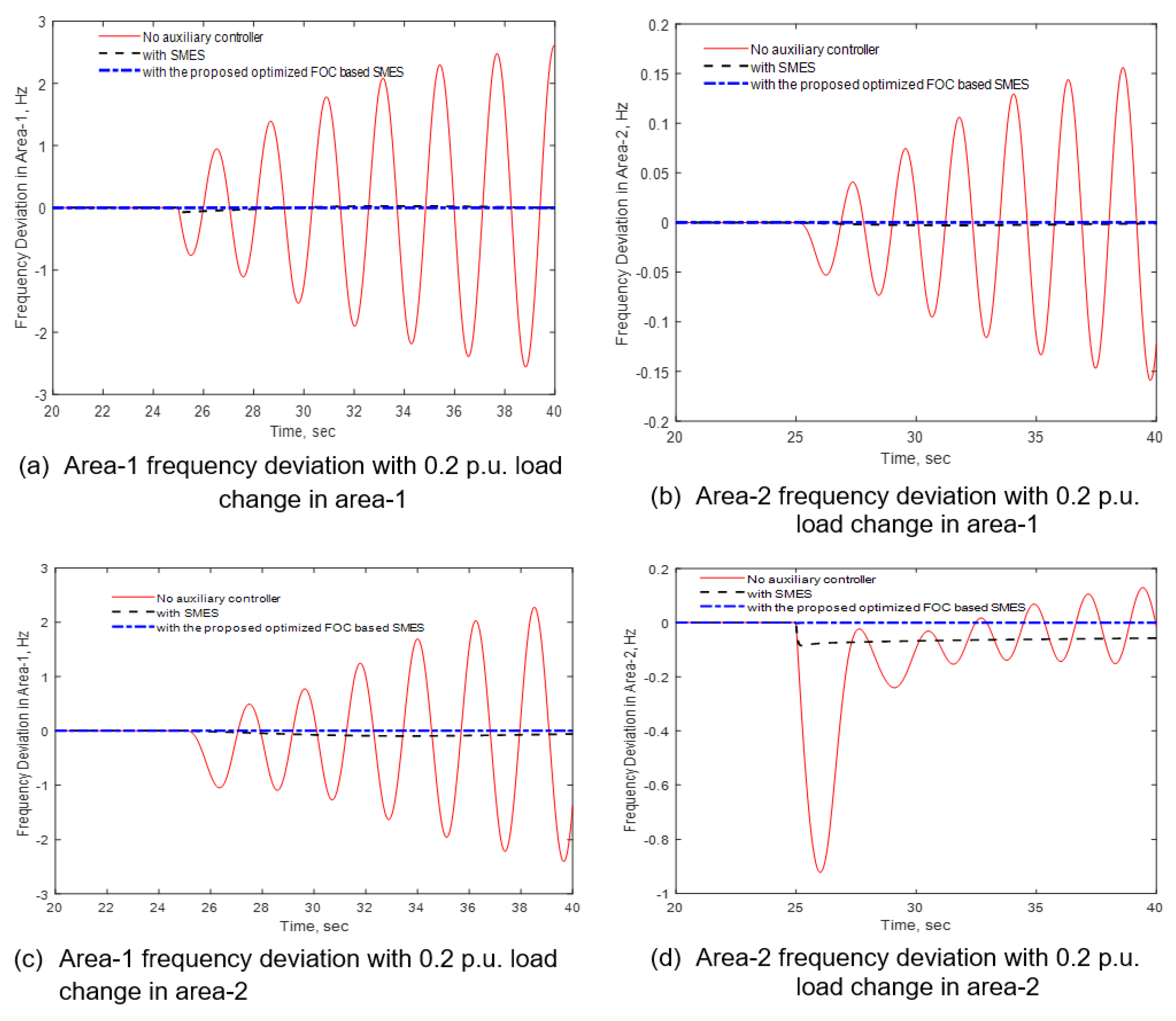
4.1.1. Load Profile Variation in Area-1

In this scenario, the studied dynamic model of the system is tested under the load profile variations in area-1. The load profiles are step changed in area-1 to observe the frequency response improvement with the proposed FOC-based SMES. The frequency deviations for area-1 and area-2 are plotted in Figure 7a,b for a step load change of 0.1 p.u. at 25 s during time domain simulation. The positive effect of the proposed controller is clearly visualized through the reduction of frequency deviations. As visualized in Figure 8a, a step load change in area-1 causes a significant frequency deviation in area- 1 without virtual inertia controller. The frequency deviation is around 1 Hz without any auxiliary controller. The conventional controller-based SMES improves the deviation to about 0.07 Hz. However, the proposed FOC-based SMES greatly improves the frequency deviation in area-1 which is around 0.01 Hz. The maximum overshoot without any auxiliary controller is 0.5 Hz whereas it is only 0.07 Hz with conventional SMES. The proposed optimized FOC-based SMES has almost zero overshoot. It is noticed that the proposed FOC-based SMES is capable of improving all the performance indices such as maximum overshoot, maximum undershoot and settling time. Likewise, the frequency deviation in area-2 is very high, around 0.04 Hz, without any inertial controller as depicted in Figure 8b. The conventional SMES controller improves frequency deviation to some extent. However, the proposed optimized FOC-based SMES reduces the frequency deviation to almost zero.
A large step load change (0.3 p.u.) is also applied in area-1 as shown in Figure 9. It is observed in Figure 9a,b that the system cannot remain in synchronism without any auxiliary controller. The frequency deviation in both areas continues to increase and the system becomes unstable. A conventional SMES system improves the frequency response keeping the frequency deviation within acceptable limit. However, a great improvement in system frequency response is observed with optimized FOC-based SMES controller which is clearly visualized in Figure 9a,b. Since the system does not return to original stable point without any auxiliary controller, the settling time is infinite. However, the settling time is improved with the conventional SMES. The proposed optimized FOC-based controller is capable to greatly improve the settling time of the frequency responses in both areas.

4.1.2. Load Profile Variation in Area-2

The load disturbances, ranging from low to high, are also applied in area-2 with the system default inertia. As depicted in Figure 10a, the frequency deviation in area-1 is 0.65 Hz without any virtual inertia controller for a step load change of 0.2 p.u. in area-1. The conventional SMES controller reduces the frequency deviation to 0.1 Hz, whereas the proposed optimized FOC controller-based SMES is capable of maintaining almost zero frequency deviation. Similarly, the frequency deviation in area-2 is 0.55 Hz without any auxiliary controller. The conventional SMES controller is capable of reducing frequency deviation by 81.8%. However, the proposed optimized FOC-based SMES controller reduces the frequency deviation by 99.21%. It is noteworthy that the settling time is slightly increased for conventional SMES controller while the frequency deviation is improved. The proposed optimized FOC-based SMES significantly reduces the settling time. The system frequency oscillates over a wide range (greater than 0.5 Hz) without any inertia controller in both areas. Since these oscillations are beyond the acceptable limits, it mandates the system frequency protection relay to operate. The proposed optimized FOC-based control scheme is capable of avoiding under frequency relay operation, thus, it improves the system reliability.
For the high step load changes in area-2 (0.3 p.u.), the frequency deviations of both areas are greater than 1 Hz which activates the under frequency relay operating set point of 59.5 Hz without any virtual inertia controller. However, the frequency deviation is well below the under frequency relay operating point with the conventional SMES controller as depicted in Figure 11a,b. In these figures, it is clearly visualized that the proposed controller is capable of keeping the frequency deviations in both areas to almost zero. Thus, the system stability and reliability are guaranteed with the proposed fractional order controller-based SMES.

4.1.3. Multiple Profile Variations in Area-1 and Area-2

In this scenario, multiple load variations as shown in Figure 12 are applied in both areas of the studied system to investigate the system’s ability to bring back the frequency deviation to zero before the next changes.
A better performance of the proposed optimized FOC-based SMES is clearly visible from the system frequency response. As seen in Figure 13a,b, following the first step load change of 0.075 p.u. at 25 s in area-1, the proposed controller is faster to eliminate the frequency deviation before beginning the second step load change of 0.15 p.u. at 50 s compared to the conventional techniques. The frequency deviations in area-1 are very high at all points of step changes without virtual inertia controller. Although the conventional SMES controller improves the frequency response slightly, a notable improvement is achieved with the proposed technique. In this case, the proposed method also provides much better performance in terms of overshoot, undershoot, and settling time. The frequency responses as visualized in Figure 13c,d show the better performance with the proposed control technique for the multiple load changes in area-2.

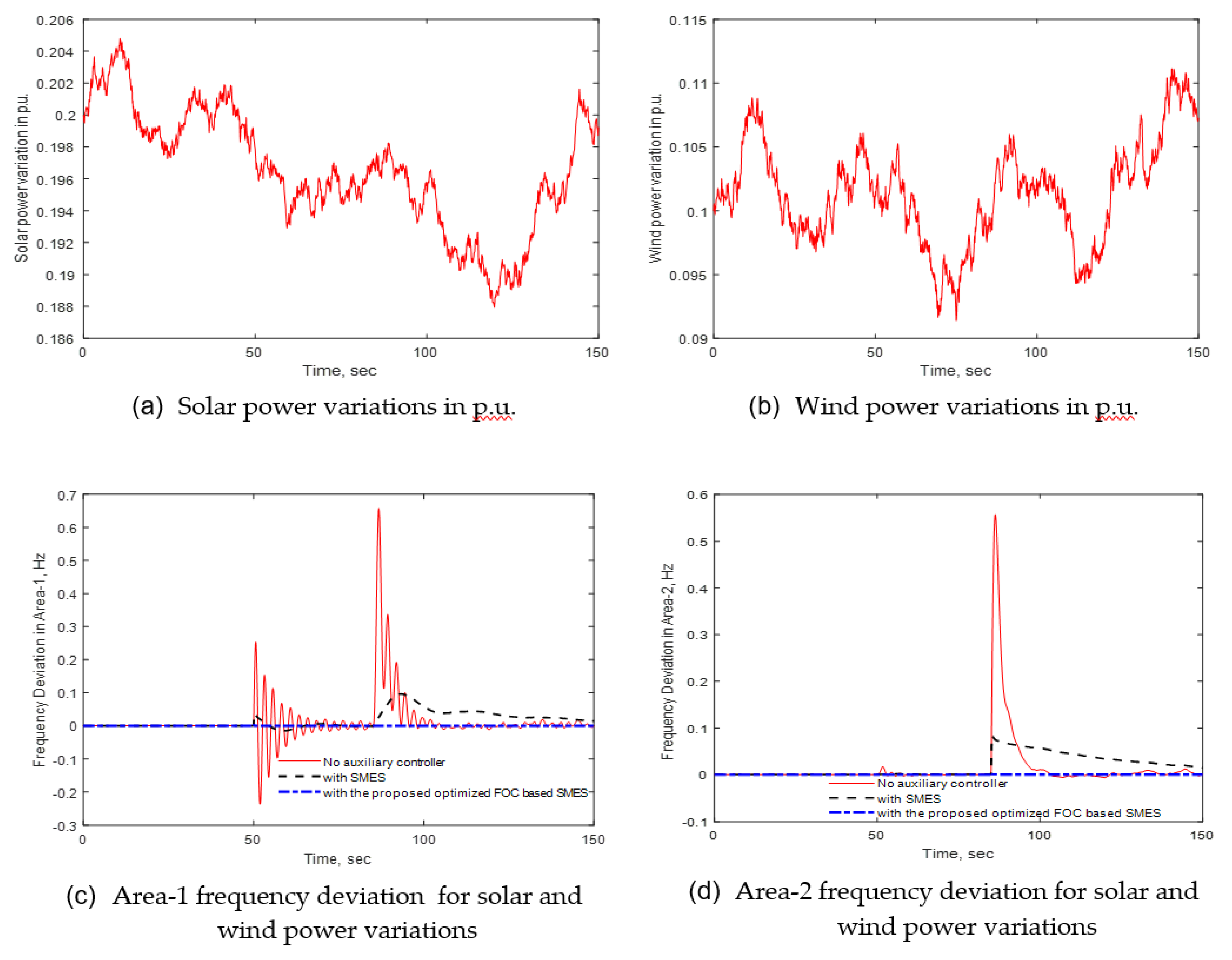
4.1.4. Frequency Response Analysis for Solar and Wind Power Variations

The effectiveness of the proposed controller is also tested with fluctuating solar and wind powers in both areas. The intermittent solar and wind powers considered in this study are depicted in Figure 14a,b, respectively. The solar and wind powers have the mean value of 0.195 p.u. and 0.10 p.u., respectively. The solar power is integrated in area-1 at 50 s during 150 s simulation time which continues to inject fluctuating power during the entire simulation period. On the other hand, the intermittent wind generating unit is connected at 75 s which is kept connected throughout the entire simulation period. As shown in Figure 14c,d, the connection of varying solar and wind powers has detrimental effect on system frequency response without any auxiliary controller. The frequency of the system continues to vary during entire simulation period and does not settle to steady state value. The conventional SMES controller slightly improves the system frequency response. On the other hand, the proposed controller performance is superior, in terms of settling time, overshoot, and undershoot, over the conventional SMES controller. The improvement of several performance indices are listed in Table 3 to demonstrate the superiority of the proposed controller.

4.1.5. Frequency Response Analysis for Reduced System Inertia

In this case, the robustness of the proposed controller is verified with the system inertia variations. The inertia in both areas is reduced by 50% and a step load change of 0.2 p.u. is applied in area-1and area-2 at 50 s. The frequency response for step load change in area-1 is depicted in Figure 15a,b. As depicted in Figure 8a,b, the system is capable of maintaining stable operation with a step load change of 0.2 p.u. in case of default inertia (100%). However, Figure 15a,b show that the frequency deviations in both areas gradually increase leading to instability. The conventional SMES controller reduces the frequency deviations and stabilizes the system. However, the proposed control method augments the system stability greatly by reducing frequency deviations to almost zero even with the 50% system inertia. Thus, the proposed controller is more robust compared to the conventional technique. The robustness of the proposed optimized FOC-based SMES is also depicted in Figure 15c,d for a 0.2 p.u. step load change in area-2. The frequency deviations in both areas are unbounded without any auxiliary controller. Although the conventional SMES makes the system stable, the proposed FOC-based SMES is superior to stabilize the system after step load disturbance.

4.2. Discussion

In this subsection, the overall performance of the proposed controller is discussed and compared to the existing methods. Moreover, the several limitations of the proposed techniques are mentioned along with the possible solution techniques. The addition of this virtual inertia with the FOC-based SMES makes the system stable over a wide range of load-generation mismatch. Since the FOC is superior over the conventional controller, the proposed technique performs better in reducing system frequency deviation. Simulation results show that the proposed controller is capable of improving the settling time, maximum overshoot, and maximum undershoot of frequency deviations.
It is noteworthy that oscillations are beyond the acceptable limits in some cases without auxiliary devices and with conventional SMES. Thus, it mandates the system frequency protection relay to operate. However, the proposed technique is capable of avoiding under frequency relay operation, which improves the system reliability. The system shows robust performance with reduced inertia as discussed in Section 4.1.5. The main disadvantage of the proposed technique is that it does not consider the optimization of the number of SMES required to stabilize the system. Thus, further study is needed to analyze the cost-benefit of the proposed FOC-based SMES technique as well as reduce the number of SMES for large power system using any suitable modern optimization technique.

5. Conclusions

This work proposes a load frequency control technique with FOC-based SMES for highly renewable energy integrated low inertia power system. A combined dynamic model of FOC, SMES, and two area power system is developed to design optimized parameters with WOA and facilitate several case studies. The system and the designed controllers are simulated in MATLAB Simulink environment considering light and heavy load disturbances, fluctuating solar and wind powers, and reduced system inertia to test the effectiveness and robustness. The simulated results confirm the promising performance in reducing system frequency deviations and improving frequency stability of the system. The proposed FOC-based controller is superior over conventional SMES controller employing feedback and proportional gains in reducing settling time, overshoot and undershoot as evident from the analysis. Moreover, the simulation outcomes demonstrate the potential benefits of FOC-based energy storage in high-level renewable energy integration and endorse the green effort to improve the sustainability. Finally, the large-scale DFIG offshore wind farm detail model with FOC-based SMES virtual inertia controller can be studied as future work.

Author Contributions

M.S.A. initiated the idea and designed the controller. M.S.A. and M.A.A. (Md Ahsanul Alam) did the simulations and drafted the article. M.S.A., M.A.A. (Majed A. Alotaibi), M.A.H., M.S., F.S.A.-I., M.M.U.R., M.A.A. (Muhammed A. Abido) initiated the conceptualization. M.S.A. did the formal analysis. All authors contributed towards extensive revisions of the article. All authors have read and agreed to the published version of the manuscript.

Funding

Md. Shafiul Alam, Mohammad A. Abido, and Fahad Saleh Al-Ismail would like to acknowledge the support provided by K.A. CARE energy research and innovation center (ERIC), and Deanship of Research (DSR) funded project No. DF181035, King Fahd University of Petroleum & Minerals (KFUM), Saudi Arabia. Majed A. Alotaibi would like to acknowledge the support provided by the researcher supporting project under project number RSP-2020/278, King Saud University, Saudi Arabia.

Conflicts of Interest

The authors declare no conflict of interest.

Abbreviations and Symbols

RESsRenewable energy sourcesTATabu search
FOCFractional order controllerGDBGenerator dead band
SMESSuperconducting magnetic energy storageGRCGeneration rate constraint
WOAWhale optimization algorithmHInertia constant
RoCoFRate of change of frequencyDDamping constant
SGSynchronous generatorPCSPower conversion system
PV Photovoltaic α Thyristor firing angle
LFCLoad frequency controlKSMESSMES proportional gain
PIDProportional integral derivativeKIDSMES feedback gain
MPCModel predictive controllerKpProportional gain
BESSBattery energy storage systemKiIntegral gain
DFIGDoubly fed induction generatorλFractional order
CCFCCapability coordinated frequency control fFrequency deviation
PSOParticle swarm optimization T D C Converter delay time
MPSOModified PSO Δ I D Incremental current change
NSGANon-dominated sorting genetic algorithm Genetic algorithm Δ E D Incremental voltage change
GAGenetic algorithmRDDamping resistor
ABCAnt bee colony

References

  1. Ekkert, M. Global Energy Transformation: A Roadmap to 2050; The International Renewable Energy Agency (IRENA): Abu Dhabi, United Arab Emirates, 2018. [Google Scholar]
  2. Alam, M.S.; Al-Ismail, F.S.; Salem, A.; Abido, M.A. High-Level Penetration of Renewable Energy Sources into Grid Utility: Challenges and Solutions. IEEE Access 2020, 8, 190277–190299. [Google Scholar] [CrossRef]
  3. Alam, S.; Ali, M.; Abido, Y.; Hussein, A.E. Fault Ride through Capability Augmentation of a DFIG-Based Wind Integrated VSC-HVDC System with Non-Superconducting Fault Current Limiter. Sustainability 2019, 11, 1232. [Google Scholar] [CrossRef] [Green Version]
  4. Milano, F.; Dörfler, F.; Hug, G.; Hill, D.J.; Verbič, G. Foundations and Challenges of Low-Inertia Systems (Invited Paper). In Proceedings of the 2018 Power Systems Computation Conference (PSCC), Dublin, Ireland, 11–15 June 2018; pp. 1–25. [Google Scholar]
  5. Sarojini, K.; Palanisamy, K.; Yang, G. Future low-inertia power systems: Requirements, issues, and solutions—A review. Renew. Sustain. Energy Rev. 2020, 124, 109773. [Google Scholar]
  6. Hajiakbari Fini, M.; Hamedani Golshan, M.E. Frequency control using loads and generators capacity in power systems with a high penetration of renewables. Electr. Power Syst. Res. 2019, 166, 43–51. [Google Scholar] [CrossRef]
  7. Ulbig, A.; Borsche, T.S.; Andersson, G. Impact of Low Rotational Inertia on Power System Stability and Operation; IFAC: Cape Town, South Africa, 2014; Volume 19, ISBN 9783902823625. [Google Scholar]
  8. Alam, M.S.; Abido, M.A.Y.; El-Amin, I. Fault Current Limiters in Power Systems: A Comprehensive Review. Energies 2018, 11, 1025. [Google Scholar] [CrossRef] [Green Version]
  9. Yu, M.; Roscoe, A.J.; Dyśko, A.; Booth, C.D.; Ierna, R.; Zhu, J.; Urdal, H. Instantaneous penetration level limits of nonsynchronous devices in the British power system. IET Renew. Power Gener. 2017, 11, 1211–1217. [Google Scholar] [CrossRef] [Green Version]
  10. Saxena, P.; Singh, N.; Pandey, A.K. Enhancing the dynamic performance of microgrid using derivative controlled solar and energy storage based virtual inertia system. J. Energy Storage 2020, 31, 101613. [Google Scholar] [CrossRef]
  11. Pradhan, C.; Bhende, C. Enhancement in Primary Frequency Contribution using Dynamic Deloading of Wind Turbines. IFAC-PapersOnLine 2015, 48, 13–18. [Google Scholar] [CrossRef]
  12. Ma, H.T.; Chowdhury, B.H. Working towards frequency regulation with wind plants Combined control approaches. IET Renew. Power Gener. 2010, 4, 308–316. [Google Scholar] [CrossRef]
  13. Haes Alhelou, H.; Hamedani-Golshan, M.E.; Zamani, R.; Heydarian-Forushani, E.; Siano, P. Challenges and Opportunities of Load Frequency Control in Conventional, Modern and Future Smart Power Systems: A Comprehensive Review. Energies 2018, 11, 2497. [Google Scholar] [CrossRef] [Green Version]
  14. Kerdphol, T.; Watanabe, M.; Mitani, Y.; Phunpeng, V. Applying virtual inertia control topology to SMES system for frequency stability improvement of low-inertia microgrids driven by high renewables. Energies 2019, 12, 3902. [Google Scholar] [CrossRef] [Green Version]
  15. Cheema, K.M. A comprehensive review of virtual synchronous generator. Int. J. Electr. Power Energy Syst. 2020, 120, 106006. [Google Scholar] [CrossRef]
  16. Bevrani, H.; Ise, T.; Miura, Y. Virtual synchronous generators: A survey and new perspectives. Int. J. Electr. Power Energy Syst. 2014, 54, 244–254. [Google Scholar] [CrossRef]
  17. Tamrakar, U.; Shrestha, D.; Maharjan, M.; Bhattarai, B.P.; Hansen, T.M.; Tonkoski, R. Virtual inertia: Current trends and future directions. Appl. Sci. 2017, 7, 654. [Google Scholar] [CrossRef]
  18. Ali, M.H.; Wu, B.; Dougal, R.A. An Overview of SMES Applications in Power and Energy Systems. IEEE Trans. Sustain. Energy 2010, 1, 38–47. [Google Scholar] [CrossRef]
  19. Muttaqi, K.M.; Islam, M.R.; Sutanto, D. Future Power Distribution Grids: Integration of Renewable Energy, Energy Storage, Electric Vehicles, Superconductor, and Magnetic Bus. IEEE Trans. Appl. Supercond. 2019, 29, 1–5. [Google Scholar] [CrossRef] [Green Version]
  20. Thiesen, H.; Jauch, C.; Gloe, A. Design of a system substituting today’s inherent inertia in the European continental synchronous area. Energies 2016, 9, 582. [Google Scholar] [CrossRef] [Green Version]
  21. Hasanien, H.M.; El-Fergany, A.A. Symbiotic organisms search algorithm for automatic generation control of interconnected power systems including wind farms. IET Gener. Transm. Distrib. 2017, 11, 1692–1700. [Google Scholar] [CrossRef]
  22. WU, Q.; Bao, W.; Ding, L.; Huang, S.; Teng, F. Synthetic Inertial Control of Wind Farm with BESS Based on Model Predictive Control. IET Renew. Power Gener. 2020, 14, 2447–2455. [Google Scholar] [CrossRef]
  23. Gomez, L.A.G.; Grilo, A.P.; Salles, M.B.C.; Filho, A.J.S. Combined control of DFIG-based wind turbine and battery energy storage system for frequency response in microgrids. Energies 2020, 13, 894. [Google Scholar] [CrossRef] [Green Version]
  24. Yang, L.; Hu, Z.; Xie, S.; Kong, S.; Lin, W. Adjustable virtual inertia control of supercapacitors in PV-based AC microgrid cluster. Electr. Power Syst. Res. 2019, 173, 71–85. [Google Scholar] [CrossRef]
  25. Magdy, G.; Mohamed, E.A.; Shabib, G.; Elbaset, A.A.; Mitani, Y. SMES based a new PID controller for frequency stability of a real hybrid power system considering high wind power penetration. IET Renew. Power Gener. 2018, 12, 1304–1313. [Google Scholar] [CrossRef]
  26. Magdy, G.; Shabib, G.; Elbaset, A.A.; Mitani, Y. A novel coordination scheme of virtual inertia control and digital protection for microgrid dynamic security considering high renewable energy penetration. IET Renew. Power Gener. 2019, 13, 462–474. [Google Scholar] [CrossRef]
  27. Kerdphol, T.; Watanabe, M.; Hongesombut, K.; Mitani, Y. Self-Adaptive Virtual Inertia Control-Based Fuzzy Logic to Improve Frequency Stability of Microgrid with High Renewable Penetration. IEEE Access 2019, 7, 76071–76083. [Google Scholar] [CrossRef]
  28. Kim, J.; Muljadi, E.; Gevorgian, V.; Mohanpurkar, M.; Luo, Y.; Hovsapian, R.; Koritarov, V. Capability-coordinated frequency control scheme of a virtual power plant with renewable energy sources. IET Gener. Transm. Distrib. 2019, 13, 3642–3648. [Google Scholar] [CrossRef]
  29. Abo-Elyousr, F.K.; Abdelaziz, A.Y. A Novel Modified Robust Load Frequency Control for Mass-Less Inertia Photovoltaics Penetrations via Hybrid PSO-WOA Approach. Electr. Power Compon. Syst. 2019, 47, 1744–1758. [Google Scholar] [CrossRef]
  30. Yap, K.Y.; Sarimuthu, C.R.; Lim, J.M.Y. Grid Integration of Solar Photovoltaic System Using Machine Learning-Based Virtual Inertia Synthetization in Synchronverter. IEEE Access 2020, 8, 49961–49976. [Google Scholar] [CrossRef]
  31. Zhang, X.; Zhu, Z.; Fu, Y.; Li, L. Optimized virtual inertia of wind turbine for rotor angle stability in interconnected power systems. Electr. Power Syst. Res. 2020, 180, 106157. [Google Scholar] [CrossRef]
  32. Alam, M.S.; Razzak, M.A.; Shafiullah, M.; Chowdhury, A.H. Application of TCSC and SVC in damping oscillations in Bangladesh Power System. In Proceedings of the 7th International Conference on Electrical and Computer Engineering, Dhaka, Bangladesh, 20–22 December 2012; IEEE: New York, NY, USA, 2012; pp. 571–574. [Google Scholar] [CrossRef]
  33. Pappachen, A.; Fathima, A.P. Load frequency control in deregulated power system integrated with SMES–TCPS combination using ANFIS controller. Int. J. Electr. Power Energy Syst. 2016, 82, 519–534. [Google Scholar] [CrossRef]
  34. Birs, I.; Muresan, C.; Nascu, I.; Ionescu, C. A Survey of Recent Advances in Fractional Order Control for Time Delay Systems. IEEE Access 2019, 7, 30951–30965. [Google Scholar] [CrossRef]
  35. Padula, F.; Visioli, A. Tuning rules for optimal PID and fractional-order PID controllers. J. Process Control 2011, 21, 69–81. [Google Scholar] [CrossRef]
  36. Muresan, C.I.; Dutta, A.; Dulf, E.H.; Pinar, Z.; Maxim, A.; Ionescu, C.M. Tuning algorithms for fractional order internal model controllers for time delay processes. Int. J. Control 2016, 89, 579–593. [Google Scholar] [CrossRef]
  37. Shah, P.; Agashe, S. Review of fractional PID controller. Mechatronics 2016, 38, 29–41. [Google Scholar] [CrossRef]
  38. Cao, J.Y.; Liang, J.; Cao, B.G. Optimization of Fractional Order PID controllers based on genetic algorithms. In Proceedings of the International Conference Machine and Learning Cybernetics ICMLC, Guangzhou, China, 18–21 August 2005; Springer: Berlin/Heidelberg, Germany, 2005; pp. 5686–5689. [Google Scholar] [CrossRef]
  39. Chang, L.Y.; Chen, H.C. Tuning of fractional PID controllers using adaptive genetic algorithm for active magnetic bearing system. WSEAS Trans. Syst. 2009, 8, 158–167. [Google Scholar]
  40. Aghababa, M.P. Optimal design of fractional-order PID controller for five bar linkage robot using a new particle swarm optimization algorithm. Soft Comput. 2016, 20, 4055–4067. [Google Scholar] [CrossRef]
  41. Biswas, A.; Das, S.; Abraham, A.; Dasgupta, S. Design of fractional-order PIλDμ controllers with an improved differential evolution. Eng. Appl. Artif. Intell. 2009, 22, 343–350. [Google Scholar] [CrossRef]
  42. Pan, I.; Das, S. Fractional-order load-frequency control of interconnected power systems using chaotic multi-objective optimization. Appl. Soft Comput. J. 2015, 29, 328–344. [Google Scholar] [CrossRef] [Green Version]
  43. Kesarkar, A.A.; Selvaganesan, N. Tuning of optimal fractional-order PID controller using an artificial bee colony algorithm. Syst. Sci. Control Eng. 2015, 3, 99–105. [Google Scholar] [CrossRef] [Green Version]
  44. Kumar, M.R.; Deepak, V.; Ghosh, S. Fractional-order controller design in frequency domain using an improved nonlinear adaptive seeker optimization algorithm. Turkish J. Electr. Eng. Comput. Sci. 2017, 25, 4299–4310. [Google Scholar] [CrossRef]
  45. Mosaad, M.I. Direct power control of SRG-based WECSs using optimised fractional-order PI controller. IET Electr. Power Appl. 2020, 14, 409–417. [Google Scholar] [CrossRef]
  46. Ateş, A.; Yeroglu, C. Optimal fractional order PID design via Tabu Search based algorithm. ISA Trans. 2016, 60, 109–118. [Google Scholar] [CrossRef]
  47. Pham, Q.; Mirjalili, S.; Member, S.; Kumar, N.; Member, S. Whale Optimization Algorithm With Applications to Resource Allocation in Wireless Networks. IEEE Trans. Veh. Technol. 2020, 69, 4285–4297. [Google Scholar] [CrossRef]
  48. Lee, D.J.; Wang, L. Small-signal stability analysis of an autonomous hybrid renewable energy power generation/energy storage system part I: Time-domain simulations. IEEE Trans. Energy Convers. 2008, 23, 311–320. [Google Scholar] [CrossRef]
  49. Morsali, J.; Zare, K.; Tarafdar Hagh, M. Appropriate generation rate constraint (GRC) modeling method for reheat thermal units to obtain optimal load frequency controller (LFC). In Proceedings of the 5th Conference on Thermal Power Plants (CTPP), Tehran, Iran, 10–11 June 2014; IEEE: New York, NY, USA, 2015; pp. 29–34. [Google Scholar] [CrossRef]
  50. Alam, M.S.; Abido, M.A.Y. Fault ride-through capability enhancement of voltage source converter-high voltage direct current systems with bridge type fault current limiters. Energies 2017, 10, 1898. [Google Scholar] [CrossRef] [Green Version]
  51. Li, H.; Luo, Y.; Chen, Y. A fractional order proportional and derivative (FOPD) motion controller: Tuning rule and experiments. IEEE Trans. Control Syst. Technol. 2010, 18, 516–520. [Google Scholar] [CrossRef]
  52. Luo, Q.; Ling, Y.; Zhou, Y. Modified Whale Optimization Algorithm for Infinitive Impulse Response System Identification. Arab. J. Sci. Eng. 2020, 45, 2163–2176. [Google Scholar] [CrossRef]
  53. Mirjalili, S.; Lewis, A. The Whale Optimization Algorithm. Adv. Eng. Softw. 2016, 95, 51–67. [Google Scholar] [CrossRef]
Figure 1. Renewable energy integrated two area power system.
Electronics 10 00511 g001
Figure 2. The dynamic model of two area system with proposed controller.
Electronics 10 00511 g002
Figure 3. SMES basic configuration.
Electronics 10 00511 g003
Figure 4. Dynamic model of SMES along with FOC.
Electronics 10 00511 g004
Figure 5. The integer order and fractional order PI.
Electronics 10 00511 g005
Figure 6. The WOA flow chart for optimizing control parameter.
Electronics 10 00511 g006
Figure 7. Convergence of WOA algorithm for FOC-based SMES design.
Electronics 10 00511 g007
Figure 8. Frequency response for 0.2 p.u. load change in area-1.
Electronics 10 00511 g008
Figure 9. Frequency response for 0.3 p.u. load change in area-1.
Electronics 10 00511 g009
Figure 10. Frequency response for 0.2 p.u. load change in area-2.
Electronics 10 00511 g010
Figure 11. Frequency response for 0.3 p.u. load change in area-2.
Electronics 10 00511 g011
Figure 12. Multiple load profile variations.
Electronics 10 00511 g012
Figure 13. Frequency response for both areas under multiple load profile variations.
Electronics 10 00511 g013
Figure 14. Frequency response for both areas under multiple load profile variations.
Electronics 10 00511 g014
Figure 15. Frequency response for both areas for step load change with 50% reduced inertia.
Electronics 10 00511 g015
Table 1. System Parameters.
ParametersValue
Area-1Area-2
Inertia0.0820.13
Damping constant0.01650.0195
Solar system time constant1.21.2
Wind system time constant1.41.4
Frequency bias factor0.36740.4103
Maximum limit of valve gate0.50.5
Minimum limit of valve gate−0.5−0.5
Synchronizing coefficient0.090.09
Area capacity ratio−0.0550.055
GRC0.30.3
Table 2. Optimized Controller Parameters.
Optimized Parameters
Parameters NameValueParameters NameValue
K p 1 13.0182 K 1 0.1595
K i 1 110.428 K 2 0.2360
λ 1 0.88310 K I D 1 0.0053
K p 2 35.1420 K S M E S 1 3.0000
K i 2 130.815 K I D 2 0.0053
λ 2 0.51580 K S M E S 2 2.8051
Table 3. Performance indices improvement with FOC-based SMES.
IndicesNo Auxiliary ControllerWith SMESOptimized FOC-Based SMES
Maximum overshoot, Hz0.6500.1000.004
Maximum undershoot, Hz0.2500.0250.000
Settling time, secinf00750.900
Publisher’s Note: MDPI stays neutral with regard to jurisdictional claims in published maps and institutional affiliations.

