The multicast source can send multicast packets without knowing the group members. After receiving the multicast packet identified by the MGEID for the first time, the SER needs to initialize the NFT entry of the MGEID and register the mapping between the MGEID and its NA with NRS. The establishment and destruction of multicast communication are completed through control signalings. The receiver can send the corresponding control signaling to join or leave the specified multicast group. In this section, we introduce the multicast mechanism of AHHM in detail from four aspects: joining a group, MJN selection, leaving a group, and data forwarding.
4.1. Joining a Group
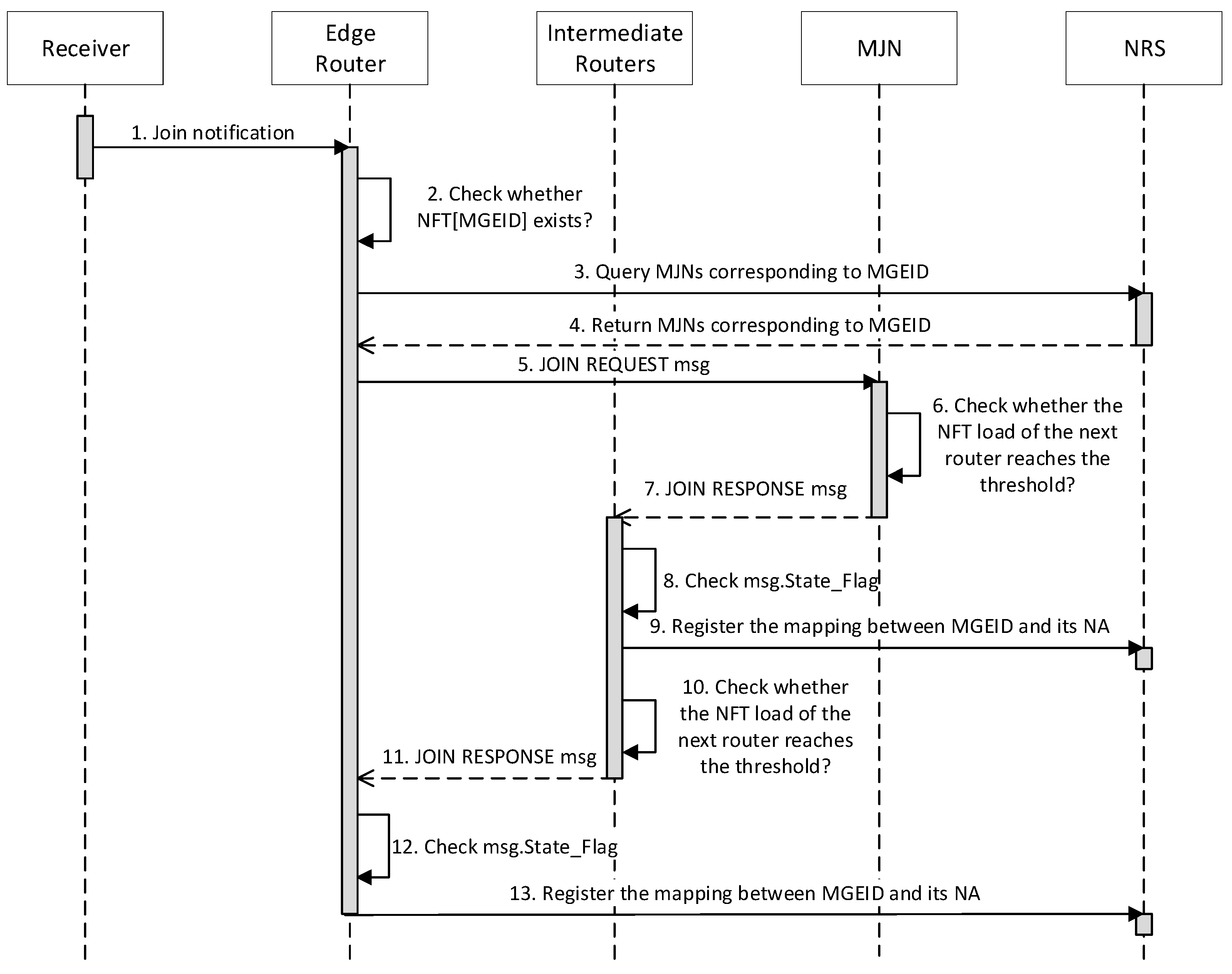
The process of the receiver joining the multicast group is shown in
Figure 2. If a receiver is interested in the multicast group identified by the MGEID, it informs the RER it connected to join the group (arrow 1). Then, the RER checks whether it contains the NFT entry of the MGEID (arrow 2). If so, the RER just inserts the interface connected to the receiver into the out-interface list of the NFT entry. Otherwise, the RER needs to initialize the NFT entry in which the Parent NA is empty, query the NRS for corresponding MJNs (arrows 3-4), select an appropriate MJN according to the given selection strategy, and then send a JOIN REQUEST message to the selected MJN (arrow 5).
After receiving the JOIN REQUEST message, the selected MJN checks whether the NFT load of the next router from it to the RER reaches the threshold (arrow 6). If the NFT load of the next router reaches the threshold, the MJN first inserts the mapping between the MGEID and the RID of the RER into its GMT and then replies to RER with a JOIN RESPONSE message in which the State Flag is set to stateless and the Parent NA is set to its NA (arrow 7). If the NFT load of the next router is less than the threshold, the MJN first inserts the forwarding interface from it to the RER into the out-interface list of the NFT entry corresponding to the MGEID and then replies to the RER with a JOIN RESPONSE message in which the State Flag is set to stateful and Parent NA is set to its NA (arrow 7).
When the intermediate router receives the JOIN RESPONSE message, it checks the State Flag of the message (arrow 8). For the JOIN RESPONSE message in which the State Flag is stateless, the intermediate router sends the message directly to the RER (arrow 11). For the JOIN RESPONSE message in which the State Flag is stateful, the intermediate router first registers the mapping between MGEID and its NA with NRS (arrow 9). Then, the router determines whether the NFT load of the next router from it to the RER reaches the threshold (arrow 10). If so, it performs the following steps: (1) initializes the NFT entry in which the Parent NA is set to the Parent NA carried in the message and the out-interface list is empty; (2) inserts the mapping between the MGEID and the RID of the RER into its GMT; (3) modifies the State Flag of the message to stateless and the Parent NA of the message to its NA; (4) forwards the message to the RER (arrow 11). If the NFT load of the next router is less than the threshold, the router also needs to perform some steps: (1) initialize the NFT entry in which the Parent NA is set to the Parent NA carried in the message and the out-interface list contains the forwarding interface from it to the RER; (2) modify the Parent NA of the message to its NA; (3) forward the message to the RER (arrow 11).
When the RER receives the JOIN RESPONSE message sent to it, it sets the Parent NA in the NFT entry of the MGEID to the Parent NA carried in the message. Then, it checks the State Flag of the received JOIN RESPONSE message (arrow 12). If the State Flag is set to stateful, the RER needs to register the mapping between MGEID and its NA with NRS (arrow 13).
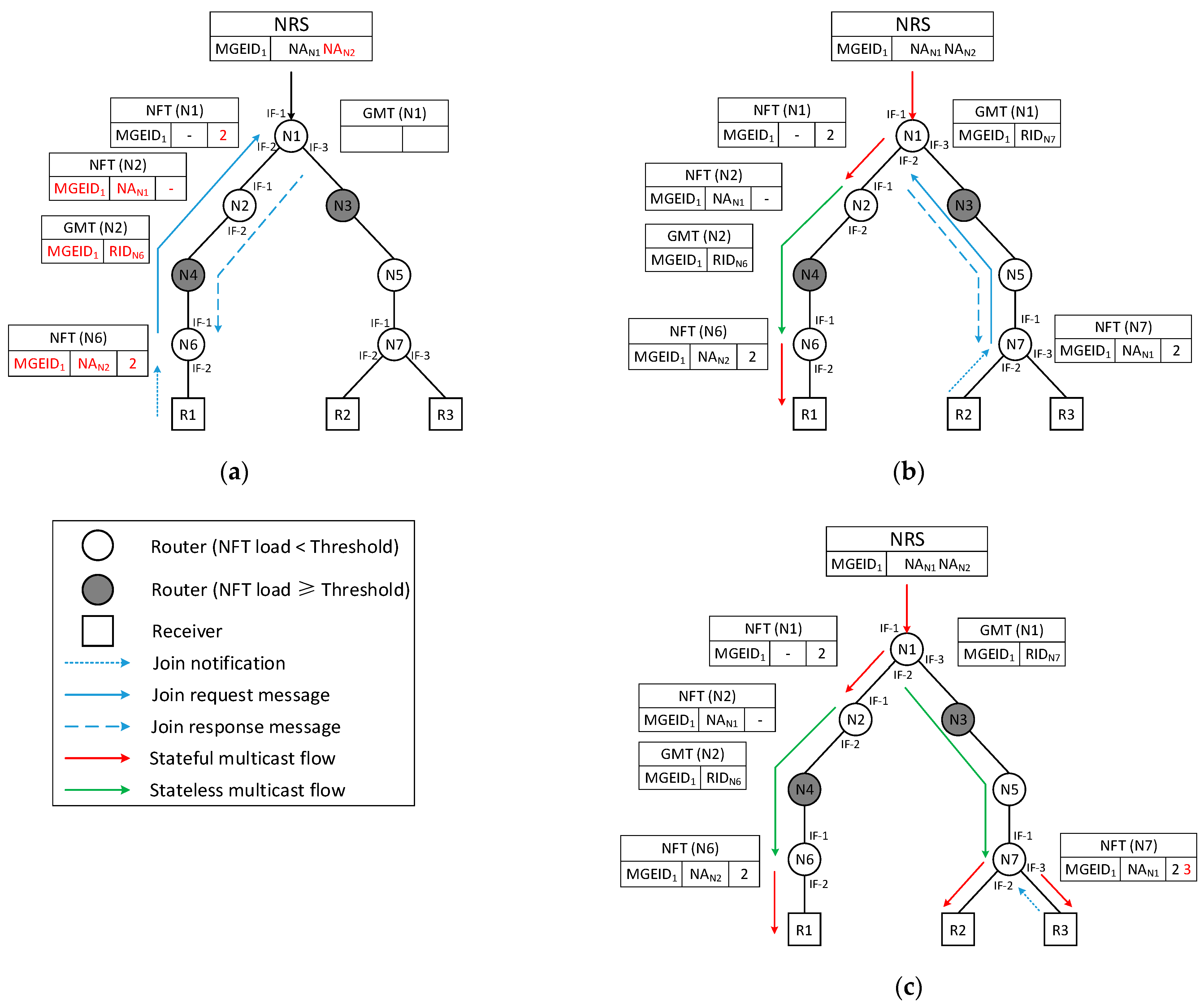
Taking the nearest MJN selection strategy as an example, we illustrate the joining process of the proposed AHHM approach in detail in
Figure 3. In the multicast group identified by MGEID
1, N1 is the MJN, and receivers R1, R2, and R3 want to join the multicast group. N1 has already initialized the NFT entry of MGEID
1 and registered the mapping between MGEID
1 and NA
N1 with NRS.
As shown in
Figure 3a, R1 informs N6 that it wants to join the multicast group identified by MGEID
1. N6 initializes the NFT entry <-, MGEID
1, 2> and obtains that the MJN of the group is NA
N1 by querying NRS. Then, N6 sends a JOIN REQUEST message to N1. After receiving the JOIN REQUEST message sent from N6, N1 finds that the NFT load of the next router (N2) from it to N6 is less than the threshold. Thus, N1 inserts the forwarding interface (2) into the out-interface list of the NFT entry and then replies to N6 with a JOIN RESPONSE message, in which the State Flag is set to stateful and Parent NA is set to NA
N1. After receiving the JOIN RESPONSE message, N2 first registers the mapping between MGEID
1 and NA
N2 with NRS. Then, N2 finds that the NFT load of the next router (N4) from it to N6 reaches the threshold, so it adds the NFT entry <NA
N1, MGEID
1, -> and adds the GMT entry <MGEID
1, RID
N6>. Finally, N2 sets the State Flag in the message to stateless, modifies the Parent NA of the message to NA
N2, and forwards the message to N6. N4 just forwards the JOIN RESPONSE message with the stateless flag to N6. When N6 receives the JOIN RESPONSE message, it sets the Parent NA of the NFT entry to NA
N2.
As shown in
Figure 3b, when N7 is notified that R2 wants to join the multicast group identified by MGEID
1, it first initializes the NFT entry <-, MGEID
1, 2>. Then, N7 obtains that MJNs of the group are NA
N1 and NA
N2 by querying NRS. N7 selects the nearest NA (NA
N1) as target MJN and sends a JOIN REQUEST message to the N1. After receiving the JOIN REQUEST message, N1 finds that the NFT load of the next router (N3) from it to N7 reaches the threshold. Thus, N1 adds the GMT entry <MGEID
1, RID
N7> and replies to N7 with a JOIN RESPONSE message in which the State Flag is set to stateless and Parent NA is set to NA
N1. N3 and N5 directly forward the JOIN RESPONSE message with the stateless flag to N7. After receiving the JOIN RESPONSE message, N7 sets the Parent NA of the NFT entry to NA
N1. As shown in
Figure 3c, when R3 informs N7 that it wants to join the multicast group identified by MGEID
1, N7 directly inserts the interface (3) connected to R3 into the out-interface list of the NFT entry corresponding to MGEID
1.
4.2. MJN Selection
In AHHM, NRS maintains the mapping between each MGEID and NAs of the corresponding MJNs. When the RER is notified that the receiver connected to it wants to join a multicast group, it can obtain MJNs through NRS and then select a suitable MJN to join according to different strategies. For example, the RER can simply select the nearest MJN from the resolved MJNs to join.
To balance distance, forwarding state, and link load, we also designed a minimum cost MJN selection strategy. The comprehensive cost is expressed as Equation (1).
D is the distance from the user to the MJN.
is the network diameter that is defined as the distance between the two farthest nodes in the network.
is the maximum number of entries that the NFT of the router can support.
is the bandwidth of the link. We traverse the routers on the path from the MJN to the RER until the NFT load of a router reaches the threshold. The maximum NFT entry number of the traversed routers is defined as the value of the path states (PS). We use the maximum link load on the path from the MJN to the RER as the value of the path traffic (PT).
The RER can select the MJN with the minimum comprehensive cost according to Algorithm 1. For each MJN, the RER first calculates the path from MJN to it (line 4). Second, the RER checks whether intermediate nodes of the path contain the MJN corresponding to the multicast group. If so, the RER discards the MJN (lines 5–10). Third, the RER calculates the PS (lines 12–18) and PT (lines 19–23) corresponding to the MJN. Fourth, the RER calculates the cost corresponding to the MJN according to the given parameters (line 24). Finally, the RER chooses the MJN with the minimum cost as the target MJN to join.
| Algorithm 1. Minimum Cost MJN Selection Algorithm |
| | Input: |
| | Output: |
| 1: | Initialization: |
| 2: | for each in do |
| 3: | Initialize |
| 4: | Obtain the path from the to the user |
| 5: | for each router on the path do |
| 6: | if the router in the then |
| 7: |
|
| 8: | break |
| 9: |
end if |
| 10: |
end for |
| 11: | if then |
| 12: | for each router on the path do |
| 13: | if the NFT entry number of the router reaches the threshold then |
| 14: | Break |
| 15: | else if the NFT entry number of the router is larger than then |
| 16: | Set the to the NFT entry number of the router |
| 17: |
end if |
| 18: |
end for |
| 19: | for each link on the path do |
| 20: | if the load of the link is larger than then |
| 21: | Set the to the load of the link |
| 22: |
end if |
| 23: |
end for |
| 24: |
|
| 25: | if then |
| 26: |
|
| 27: |
end if |
| 28: |
end if |
| 29: | end for |
| 30: | return |
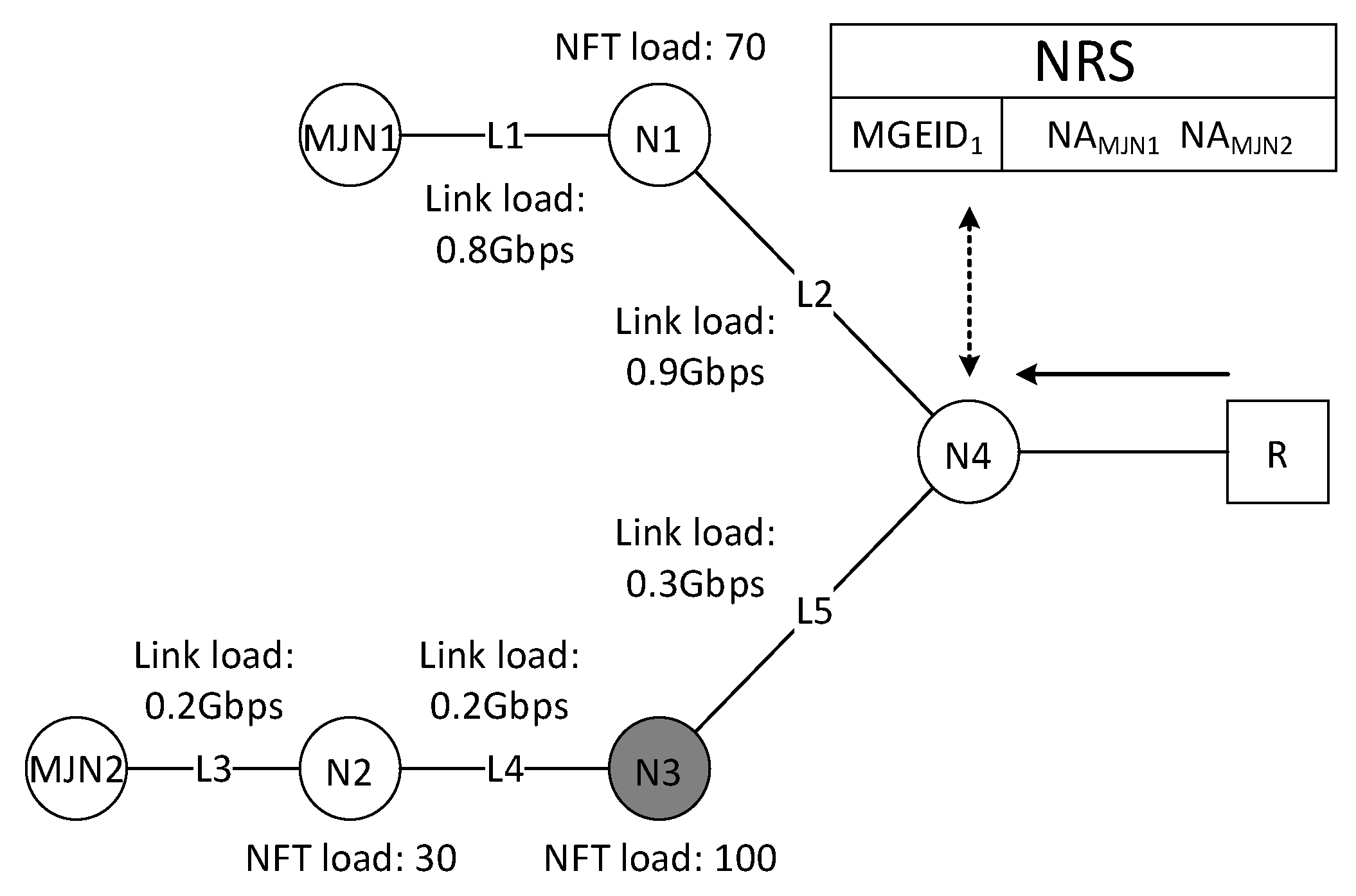
However, RER needs to detect the status of routers and links when using the maximum cost MJN selection strategy, which will increase signaling overhead. Therefore, this strategy is more suitable for use in the Software-Defined Network (SDN) environment, where the controller has global network status information. We took the scenario shown in
Figure 4 as an example to describe the minimum cost MJN selection strategy in detail. The receiver R informs N4 that it wants to join the multicast group identified by MGEID
1. Since N4 does not maintain the NFT entry corresponding to MGEID
1, N4 queries the NRS for the MJN list of the group. NRS returns NA
MJN1 and NA
MJN2 to N4. Then, N4 selects a suitable MJN to join according to the given MJN selection strategy. When using the nearest MJN selection strategy, N4 selects MJN1 as the target MJN to join because the distance between MJN1 and N4 is less than the distance between MJN2 and N4.
When using the minimum cost MJN selection strategy, N4 calculates the comprehensive cost of MJN1 and MJN2, respectively. We assume that the network diameter is 4, the link bandwidth is 1Gbps, the NFT load threshold is 100, and the α, β, and γ used in the comprehensive cost function are all 1/3. On the path from MJN1 to N4 (MJN1→N1→N4), we used the NFT load of N1 as PS and the link load of L2 as PT. Then, we calculated that the comprehensive cost of MJN1 is 0.7. The path from MJN2 to N4 is MJN2→N2→N3→N4. Since the NFT load of N3 reaches the threshold, we used the NFT load of N2 as the PS and the link load of L5 as the PT. Then we calculated that the comprehensive cost of MJN1 is 0.45. Since , N4 chooses MJN2 as the target MJN to join.
4.3. Leaving a Group
The process of the receiver joining the multicast group is shown in
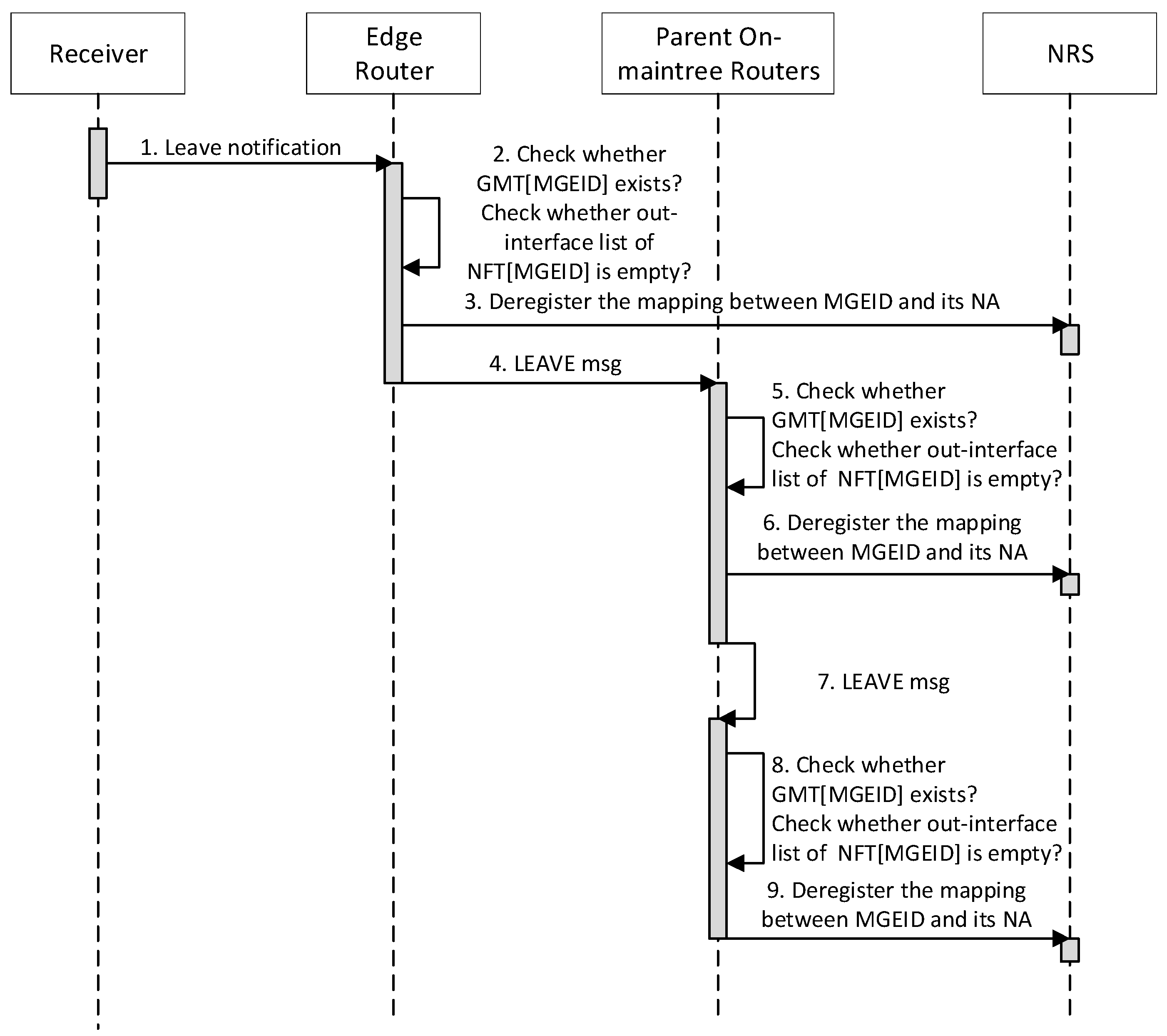
Figure 5. When a receiver is no longer interested in the multicast group identified by MGEID, it informs the RER it connected to leave the group (arrow 1). The RER removes the interface connected to the receiver from the out-interface list of the NFT entry corresponding to the MGEID. If the RER finds that its GMT does not contain the MGEID and the out-interface list of the NFT entry is empty (arrow 2), it deregisters the mapping between the MGEID and its NA with NRS (arrow 3), sends a LEAVE message containing its RID to the Parent NA of the NFT entry (arrow 4), and removes the NFT entry.
When a router receives the LEAVE message sent to it, it first checks whether its GMT contains the mapping between the MGEID and the RID carried in the message. If so, it removes the mapping between the MGEID and the RID from its GMT. Otherwise, it removes the incoming interface of the message from the out-interface list of the NFT entry corresponding to the MGEID. Then, if its GMT does not contain the MGEID and the out-interface list of the NFT entry becomes empty (arrow 5), the router deregisters the mapping between the MGEID and its NA with NRS (arrow 6), sends a LEAVE message containing its RID to the Parent NA of the NFT entry (arrow 7), and removes the NFT entry.
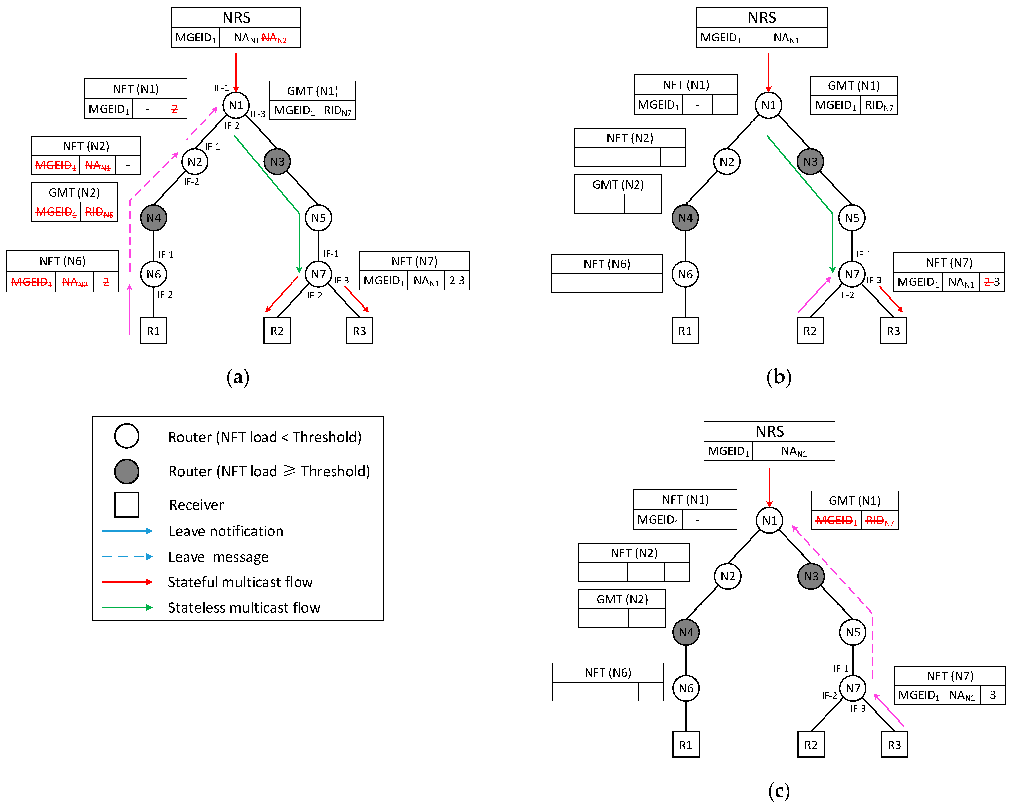
Figure 6 details the leaving process of the proposed AHMM approach. As shown in
Figure 6a, when R1 is no longer interested in the multicast group specified by MGEID
1, it just informs N6 that it wants to leave the group. Then, N6 sends a LEAVE message to N2 and removes the NFT entry of MGEID
1. After receiving the LEAVE message, N2 removes the mapping between MGEID
1 and RID
N6 from its GMT, sends a LEAVE message to N1, deregisters the mapping between MGEID
1 and NA
N2 with NRS, and removes the NFT entry. When N1 receives the LEAVE message sent from N2, it removes the incoming interface (2) of the message from the out-interface list of the NFT entry.
Then, R2 informs N7 that it wants to leave the multicast group, as shown in
Figure 6b. N7 removes the incoming interface (2) of the message from the out-interface list of the NFT entry corresponding to MGEID
1. Then, R3 also informs N7 that it wants to leave the multicast group specified by MGEID
1, as shown in
Figure 6c. N7 sends a LEAVE message to N1 and removes the NFT entry of MGEID
1. After receiving the LEAVE message sent from N7, N1 removes the mapping between MGEID
1 and RID
N7 from its GMT.
4.4. Data Forwarding
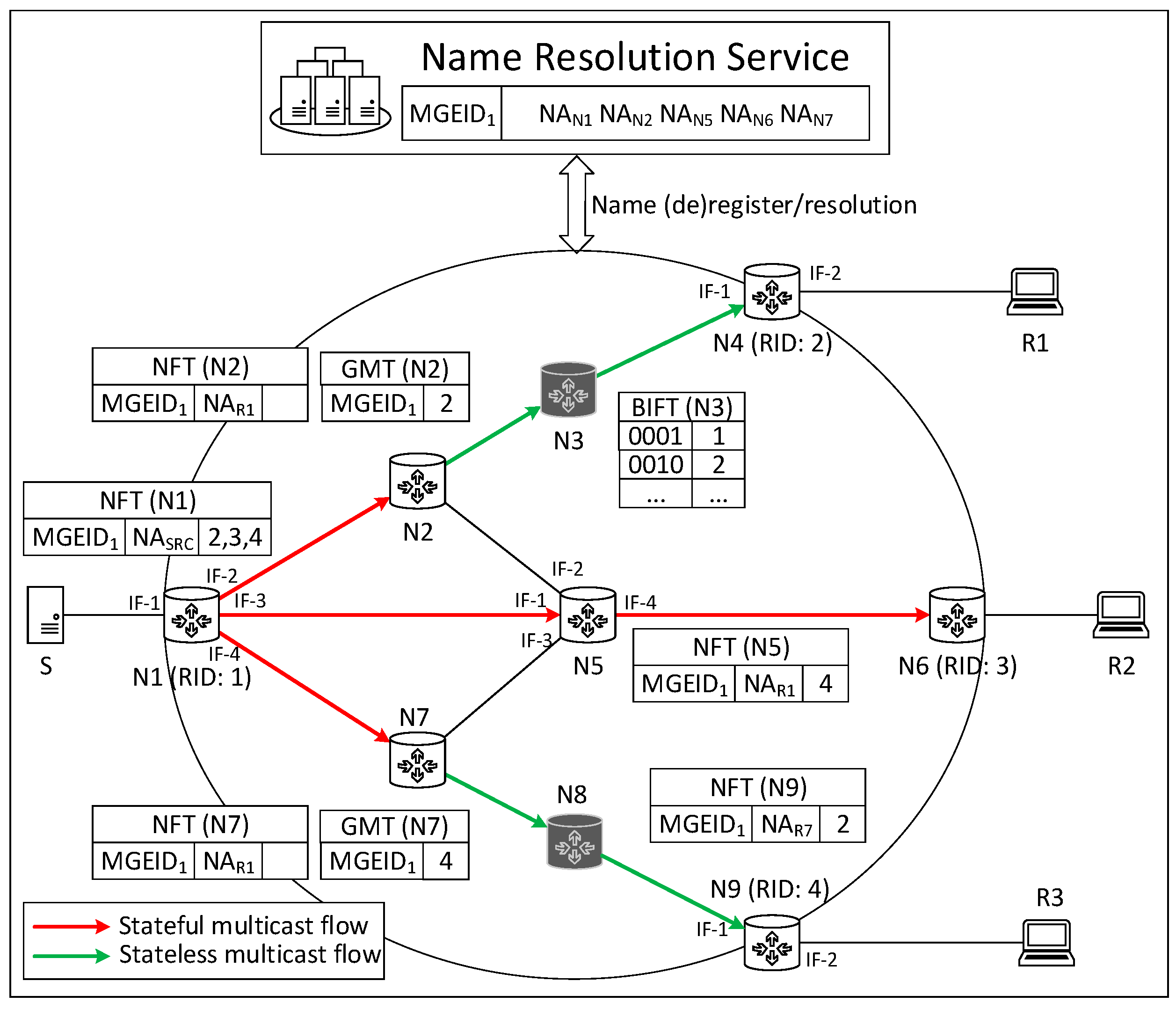
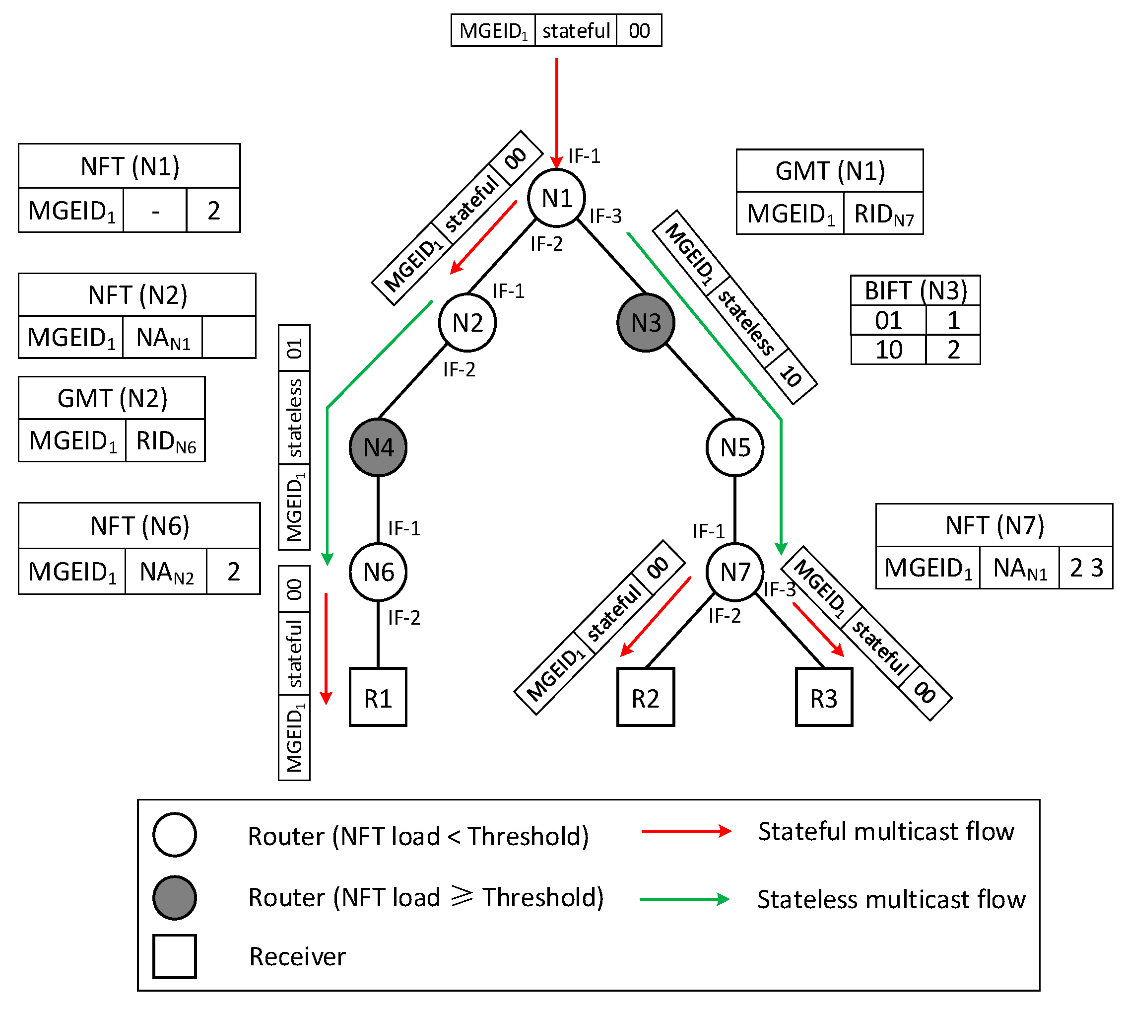
In AHHM, routers can not only forward multicast packets based on the MGEID but also forward multicast packets based on the bit string. If the State Flag of the received multicast packet is set to stateful, the router checks whether its GMT contains the MGEID. If so, it copies a packet, adds the bit string to the header of the copy, and modifies the State Flag to stateless. Then, it forwards the copy through BIFT and forwards the raw packet through NFT. Otherwise, it only needs to forward the packet through NFT. If the State Flag of the received multicast packet is set to stateless, the router checks whether the bit representing itself in the bit string is set. If so, the router clears the bit string in the message, modifies the Stateless Flag to stateful, and forwards the packet through NFT. Otherwise, the router directly forwards the raw packet through BIFT.
We took the scenario shown in
Figure 7 as the example to describe the process of data forwarding in AHHM. After receiving the multicast packet in which the State Flag is set to stateful, N1 copies the packet firstly. For the copy, N1 modifies the State Flag to stateless, sets the bit string to 10, and forwards the copy through BIFT. For the raw packet, N1 forwards it through NFT. Since the GMT contains MGEID
1, N2 copies the multicast packet with the stateful flag. For the copy, N2 modifies the State Flag to stateless, sets the bit string to 01, and then forwards the packet through BIFT. Then, N2 discards the raw packet because the out-interface list of the NFT entry is empty. N4 directly forwards the multicast packet with the stateless flag through BIFT. After receiving the stateless multicast packet in which the bit representing it in the bit string is set, N6 clears the bit string, modifies the State Flag to stateful, and then forwards the packet to R1 through NFT. N3 and N5 directly forward the multicast packet with the stateless flag through BIFT. After receiving the stateless multicast packet in which the bit representing it in the bit string is set, N7 clears the bit string, sets the State Flag to stateful, and then forwards the packet to R2 and R3 through NFT.


