
A Hybrid Antenna with Equal Beamwidth in Two Frequency Bands for Radar Applications


Abstract
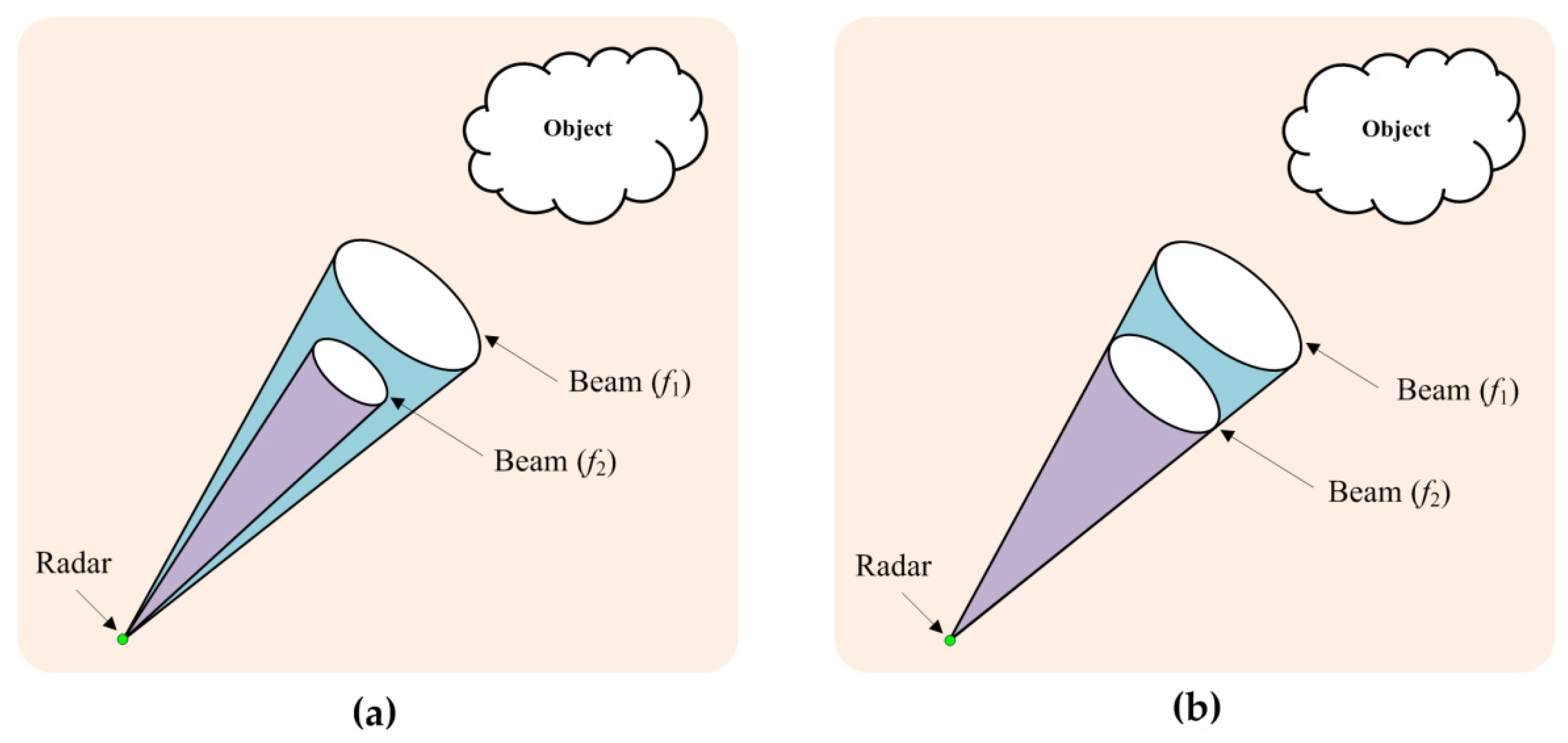
:1. Introduction
2. Antenna Design Methodology
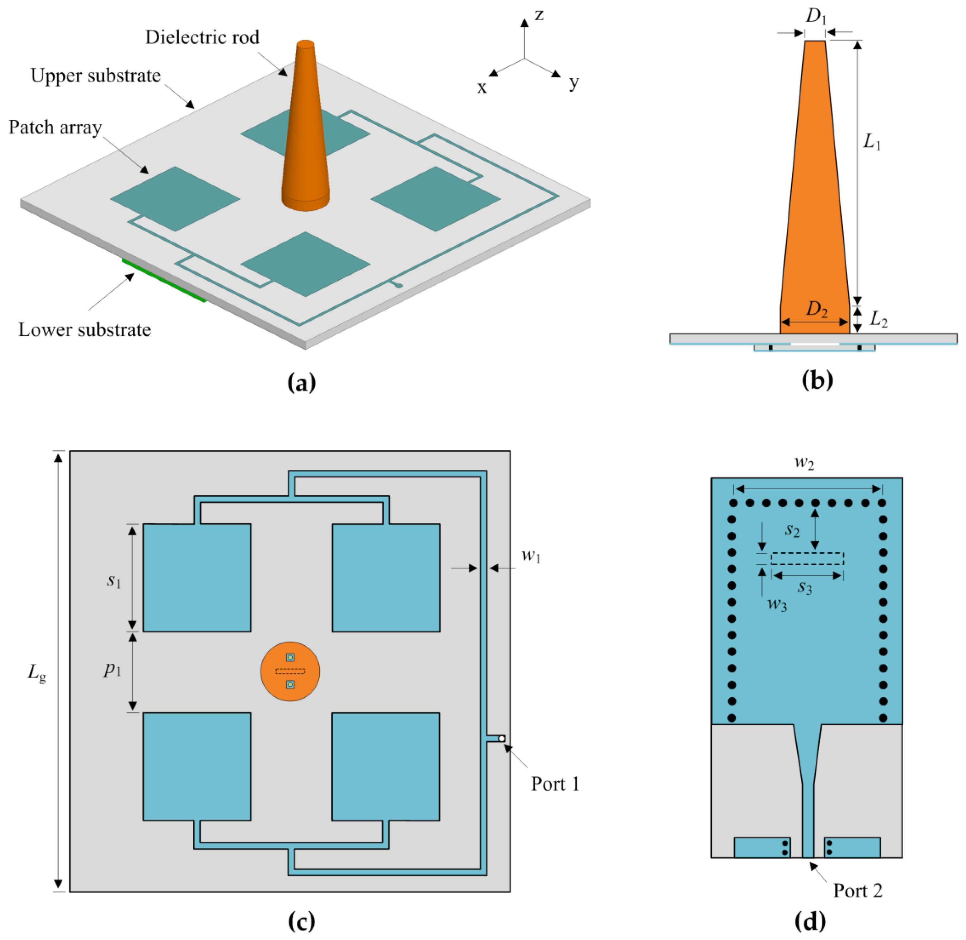
2.1. Antenna Geometery
2.2. Operating Principle of the Dielectric Rod Antenna
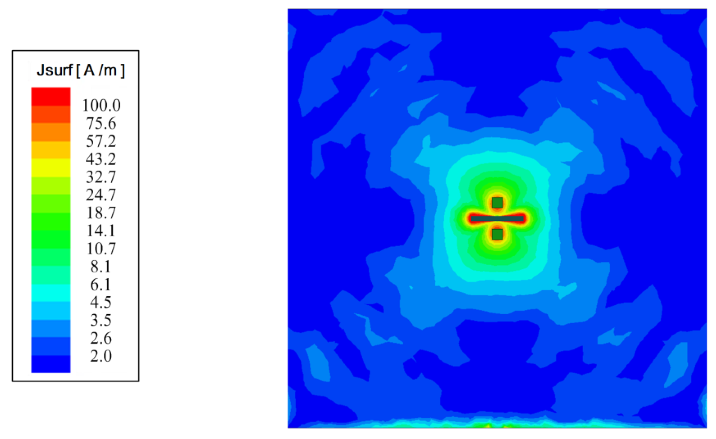
2.3. Operating Principle of the 2 × 2 Patch Array
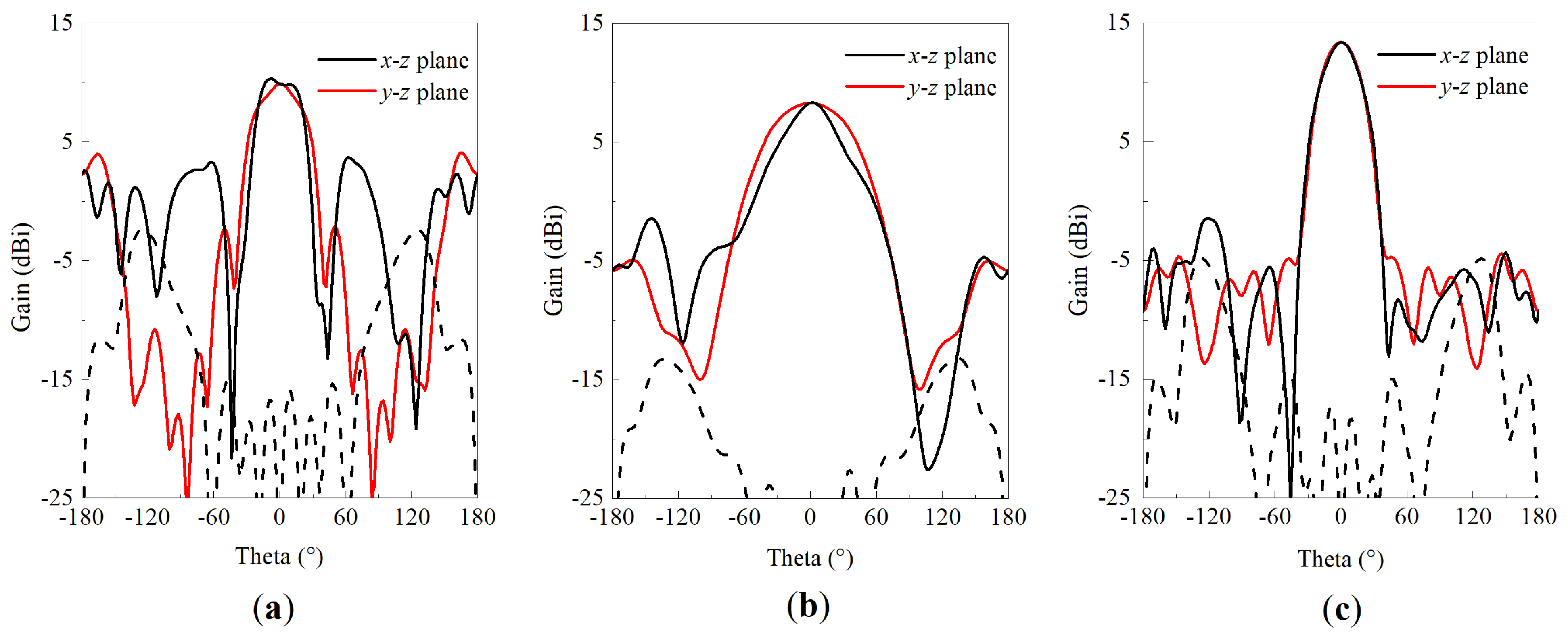
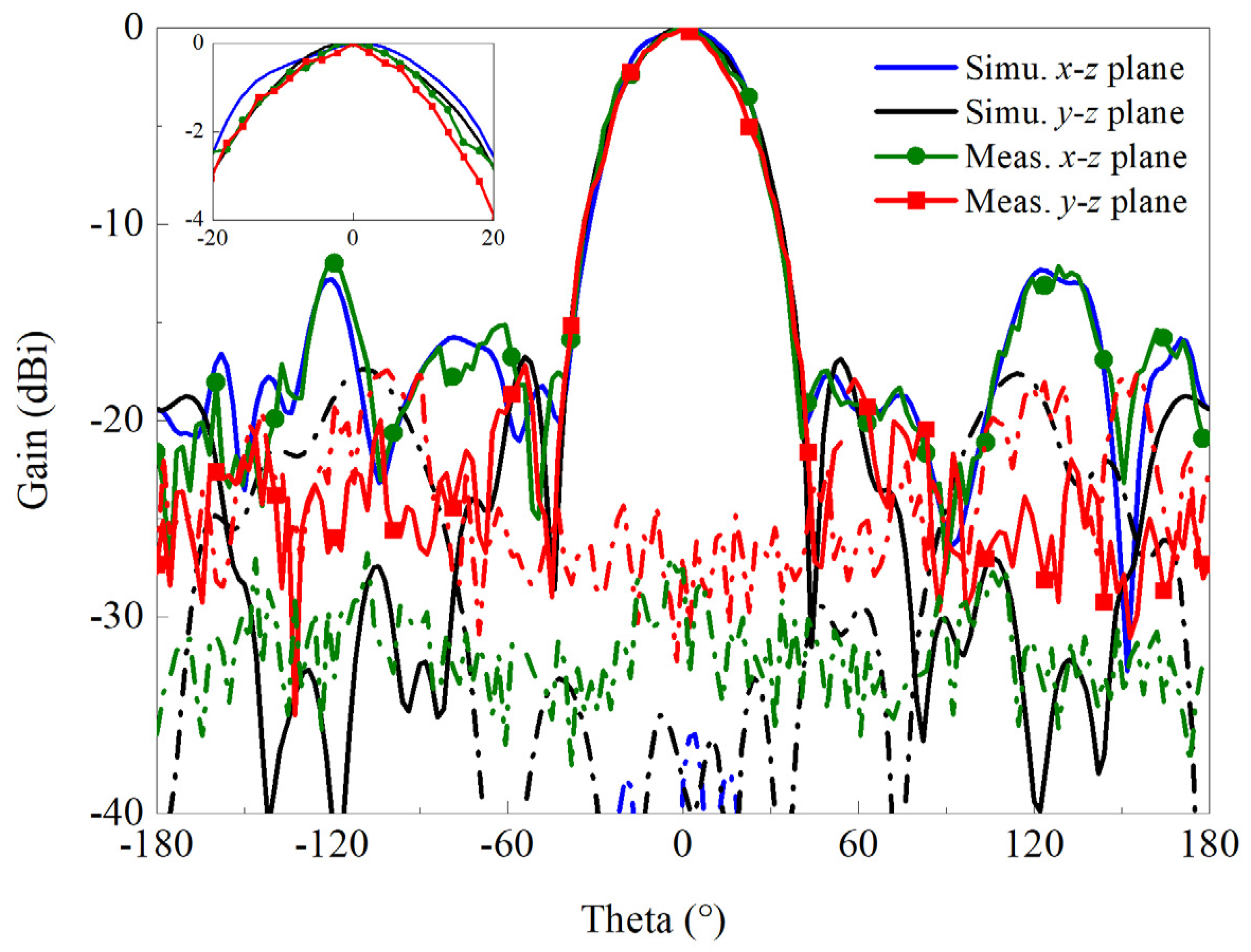
3. Experimental Results
4. Discussion
5. Conclusions
Author Contributions
Funding
Data Availability Statement
Conflicts of Interest
References
- Scotti, F.; Laghezza, F.; Onori, D.; Bogoni, A. Field trial of a photonics-based dual-band fully coherent radar system in a maritime scenario. IET Radar Sonar Navig. 2016, 11, 420–425. [Google Scholar] [CrossRef]
- Nouguier, F.; Mouche, A.; Rascle, N.; Chapron, B.; Vandemark, D. Analysis of dual-frequency ocean backscatter measurements at Ku- and Ka-bands using near-nadir incidence GPM radar data. IEEE Geosci. Remote Sens. Lett. 2016, 13, 1310–1314. [Google Scholar] [CrossRef] [Green Version]
- Jain, V.; Sundararaman, S.; Heydari, P. A single-chip dual-band 22–29-GHz/77–81-GHz BiCMOS transceiver for automotive radars. IEEE J. Solid-State Circuits 2009, 44, 3469–3485. [Google Scholar] [CrossRef]
- Schmalz, K.; Rothbart, N.; Gluck, A.; Eissa, M.H.; Mausolf, T.; Turkmen, E.; Yilmaz, S.B.; Hübers, H.-W. Dual-band transmitter and receiver with bowtie-antenna in 0.13 µm SiGeBiCMOS for gas spectroscopy at 222–270 GHz. IEEE Access 2021, 9, 12485–124816. [Google Scholar] [CrossRef]
- Maleki, A.; Oskouei, H.D.; MohammadiShirkolaei, M. Miniaturized microstrip patch antenna with high inter-port isolation for full duplex communication system. Int. J. RF MicrowComput. Aided Eng. 2021, 31, e22760. [Google Scholar] [CrossRef]
- Althuwayb, A.A. Enhanced radiation gain and efficiency of a metamaterial inspired wideband microstrip antenna using substrate integrated waveguide technology for sub-6 GHz wireless communication systems. Microw. Opt. Technol. Lett. 2021, 63, 1892–1898. [Google Scholar] [CrossRef]
- Mohammad, A.K.; Mohammad, N.M.; Ramazan, A.S. Composite right–left-handed-based antenna with wide applications in very-high frequency–ultra-high frequency bands for radio transceivers. IET Microw. Antennas Propag. 2015, 9, 1713–1726. [Google Scholar]
- Wang, J.; Ge, J.; Zhou, Y.; Xia, H.; Yang, X. Design of a high- isolation 35/94-GHz dual-frequency orthogonal-polarization Cassegrain antenna. IEEE Antennas Wirel. Propag. 2017, 16, 1297–1300. [Google Scholar] [CrossRef]
- Malfajani, R.S.; Arand, B.A. Dual-band orthogonally polarized single-layer reflectarray antenna. IEEE Trans. Antennas Propag. 2017, 65, 6145–6150. [Google Scholar] [CrossRef]
- Martinez-de-Rioja, E.; Martinez-de-Rioja, D.; López-Sáez, R.; Linares, I. High-efficiency polarizer reflectarray antennas for data transmission links from a cubeSat. Electronics 2021, 10, 1802. [Google Scholar] [CrossRef]
- Ma, X.; Huang, C.; Pan, W.; Zhao, B.; Cui, J.; Luo, X. A dual circularly polarized horn antenna in Ku-band based on chiral metamaterial. IEEE Trans. Antennas Propag. 2014, 62, 2307–2311. [Google Scholar] [CrossRef]
- Ando, T.; Ohba, I.; Numata, S.; Yamauchi, J.; Nakano, H. Linearly and curvilinearly tapered cylindrical-dielectric-rod antennas. IEEE Trans. Antennas Propag. 2005, 53, 2827–2833. [Google Scholar] [CrossRef] [Green Version]
- Nasir, M.; Xia, Y.; Jiang, M.; Zhu, Q. A novel integrated Yagi–Uda and dielectric rod antenna with low sidelobe level. IEEE Trans. Antennas. Propag. 2019, 67, 2751–2756. [Google Scholar] [CrossRef]
- Zhang, J.D.; Wu, W.; Fang, D.G. Dual-band and dual-circularly polarized shared-aperture array antennas with single-layer substrate. IEEE Trans. Antennas Propag. 2016, 64, 109–116. [Google Scholar] [CrossRef]
- Chen, C.; Liu, Z.; Wang, H.; Guo, Y. Metamaterial-inspired self polarizing dual band dual-orthogonal circularly polarized Fabry-Perot resonator antennas. IEEE Trans. Antennas Propag. 2019, 67, 1329–1334. [Google Scholar] [CrossRef]
- Catalani, A.; Toso, G.; Angeletti, P.; Albertini, M. Development of enabling technologies for Ku-band airborne SATCOM phased-arrays. Electronics 2020, 9, 488. [Google Scholar] [CrossRef] [Green Version]
- Wang, Z.; Huang, Z. A microwave/millimeter wave dual-band shared aperture patch antenna array. IEEE Access 2020, 8, 218585–218591. [Google Scholar] [CrossRef]
- Pelliccia, E.; VincentiGatti, R.V.; Angeletti, P.; Toso, G. A dual-band circularly polarized patch array antenna for phase-only beam shaping with element rotation. Electronics 2021, 10, 643. [Google Scholar] [CrossRef]
- Kothapudi, V.K.; Kumar, V. A multi-layer S/X-band shared aperture antenna array for airborne synthetic aperture radar applications. Int. J. RF Microw. Comput. Aided Eng. 2021, 31, e22720. [Google Scholar] [CrossRef]
- Li, Y.; Zhang, Z.; Zheng, J.; Feng, Z.; Iskander, M.F. A compact hepta-band loop-inverted F reconfigurable antenna for mobile phone. IEEE Trans. Antennas Propag. 2012, 60, 389–392. [Google Scholar] [CrossRef]
- Deng, C.; Li, Y.; Zhang, Z.; Pan, G.; Feng, Z. Dual-band circularly polarized rotated patch antenna with a parasitic circular patch loading. IEEE Antennas Wirel. Propag. Lett. 2013, 12, 492–495. [Google Scholar] [CrossRef]
- Xiang, B.J.; Zheng, S.Y.; Wong, H.; Pan, Y.M.; Wang, K.X.; Xia, M.H. A flexible dual-band antenna with large frequency ratio and different radiation properties over the two bands. IEEE Trans. Antennas Propag. 2018, 66, 657–667. [Google Scholar] [CrossRef]
- Tang, M.; Wu, Z.; Shi, T.; Ziolkowski, R.W. Dual-band, linearly polarized, electrically small huygens dipole antennas. IEEE Trans. Antennas Propag. 2019, 67, 37–47. [Google Scholar] [CrossRef]
- Chung, M.-A.; Yang, C.-W. Miniaturized broadband-multiband planar monopole antenna in autonomous vehicles communication system device. Electronics 2021, 10, 2715. [Google Scholar] [CrossRef]
- Li, X.-P.; Xu, G.; Ma, M.-R.; Duan, C.-J. UWB dual-band-notched lanky-leaf-shaped antenna with loaded half-square-like slots for communication system. Electronics 2021, 10, 1991. [Google Scholar] [CrossRef]
- Raheel, K.; Altaf, A.; Waheed, A.; Kiani, S.H. E-shaped H-slotted dual band mmWave antenna for 5G technology. Electronics 2021, 10, 1019. [Google Scholar] [CrossRef]
- Huang, J.; Dong, G.; Cai, J.; Li, H. A quad-port dual-band MIMO antenna array for 5G smartphone applications. Electronics 2021, 10, 542. [Google Scholar] [CrossRef]
- Ji, Z.; Wang, K.X.; Wong, H. Circularly polarized dielectric rod waveguide antenna for millimeter-wave applications. IEEE Trans. Antennas Propag. 2018, 66, 5080–5087. [Google Scholar] [CrossRef]
- Zhang, Y.; Lin, S.; Zhu, B.; Cui, J.; Denisov, A. Broadband and high gain dielectric-rod endfire antenna fed by a tapered ridge waveguide for K/Ka bands applications. IET Microw. Antennas Propag. 2020, 14, 743–751. [Google Scholar] [CrossRef]
- Sporer, M.; Weigel, R.; Koelpin, A. A 24 GHz dual-polarized and robust dielectric rod Antenna. IEEE Trans. AntennasPropag. 2017, 65, 6952–6959. [Google Scholar] [CrossRef]
- Kazemi, R.; Fathy, A.E.; Sadeghzadeh, R.A. Dielectric rod antenna array with substrate integrated waveguide planar feed network for wideband applications. IEEE Trans. Antennas Propag. 2012, 60, 1312–1319. [Google Scholar] [CrossRef]
- Ghassemi, N.; Wu, K. Planar dielectric rod antenna for gigabyte chip-to-chip communication. IEEE Trans. Antennas Propag. 2012, 60, 4924–4928. [Google Scholar] [CrossRef]
- Leib, M.; Vollmer, A.; Menzel, W. An ultra-wideband dielectric rod antenna fed by a planar circular slot. IEEE Trans. Microw. Theory Techn. 2011, 59, 1082–1089. [Google Scholar] [CrossRef]
- Patrovsky, A.; Wu, K. 94-GHz planar dielectric rod antenna with substrate integrated image guide (SIIG) feeding. IEEE Antennas Wirel. Propag. Lett. 2006, 5, 435–437. [Google Scholar] [CrossRef]
- Althuwayb, A.A. Low-interacted multiple antenna systems based on metasurface-inspired isolation approach for MIMO applications. Arab. J. Sci. Eng. 2021, e05720. [Google Scholar] [CrossRef]
- Mohammad, A.; Virdee, B.S.; Azpilicueta, L.; Naser-Moghadasi, M.; Akinsolu, M.O.; See, C.H.; Liu, B.; Abd-Alhameed, R.A.; Falcone, F.; Huynen, I.; et al. A comprehensive survey of "metamaterial transmission-line based antennas: Design, challenges, and applications. IEEE Access. 2020, 8, 144778–144808. [Google Scholar]
- Mohammadi, S.M. Wideband linear microstrip array antenna with high efficiency and low side lobe level. Int. J. RF Microw. Comput. Aided. Eng. 2020, 30, e22412. [Google Scholar]
- Wu, Q.; Luk, K.M. A broadband dual-polarized magneto-electric dipole antenna with simple feeds. IEEE Antennas Wirel. Propag. Lett. 2009, 8, 60–63. [Google Scholar]


| Parameter | Value | Parameter | Value | Parameter | Value |
|---|---|---|---|---|---|
| D1 | 3 | L2 | 2 | w2 | 11 |
| D2 | 8 | p1 | 16 | s2 | 3 |
| L1 | 29 | w1 | 0.6 | w3 | 0.5 |
| Design | f1(GHz) | f2 (GHz) | Beamwidth at f1 (°) | Beamwidth at f2 (°) | Gains at f1 and f2 (dBi) |
|---|---|---|---|---|---|
| [11] | 12.45 | 14.35 | ~13/not given | ~11/not given | ~22/23 |
| [14] | 12.1 | 17.4 | 19.1/not given | 13.1/not given | 18/18.2 |
| [15] | 7.28 | 8 | ~22/not given | ~16/not given | 12.98/13.25 |
| [18] | 1.275 | 1.575 | ~82/88 | ~74/76 | 8.2/8.7 |
| [22] | 5.8 | 30 | 22/34 | 56/68 | 10.2/8.1 |
| Proposed | 5.8 | 24 | 42/43 | 39/42 | 12.5/12.7 |
Publisher’s Note: MDPI stays neutral with regard to jurisdictional claims in published maps and institutional affiliations. |
© 2021 by the authors. Licensee MDPI, Basel, Switzerland. This article is an open access article distributed under the terms and conditions of the Creative Commons Attribution (CC BY) license (https://creativecommons.org/licenses/by/4.0/).
Share and Cite
Zhang, N.; Deng, C.; Sun, H. A Hybrid Antenna with Equal Beamwidth in Two Frequency Bands for Radar Applications. Electronics 2021, 10, 3000. https://doi.org/10.3390/electronics10233000
Zhang N, Deng C, Sun H. A Hybrid Antenna with Equal Beamwidth in Two Frequency Bands for Radar Applications. Electronics. 2021; 10(23):3000. https://doi.org/10.3390/electronics10233000
Chicago/Turabian StyleZhang, Ning, Changjiang Deng, and Houjun Sun. 2021. "A Hybrid Antenna with Equal Beamwidth in Two Frequency Bands for Radar Applications" Electronics 10, no. 23: 3000. https://doi.org/10.3390/electronics10233000