1. Introduction
With the development of power semiconductors and digital signal processors, their cost has been reduced and their performance has improved. Accordingly, motor drive systems using two inverters have been proposed to increase the power density and efficiency [
1,
2,
3,
4,
5,
6,
7,
8,
9,
10,
11,
12,
13,
14,
15,
16,
17,
18,
19,
20,
21,
22,
23]. First, an open-ended winding structure is applied to a squirrel cage induction motor (IM) or a permanent magnet motor to connect two inverters at both ends [
1,
2,
3,
4,
5]. Since the stator phase voltage is determined by the difference between the output voltages of both inverters, the applicable phase voltage increases, and the high-speed operation range is expanded. Assuming that the same DC link voltage is applied to each inverter, the maximum input voltage considering zero common mode current operation increases by
times [
2]. Another motor drive topology with two inverters is a dual stator three-phase winding motor [
6,
7,
8,
9]. In the dual three-phase winding motor, the rated current is parallelly provided by each inverter, so that twice the inverter output current can be totally applied to the motor. In addition, when a phase difference of 30 degrees is applied between dual windings, the sixth-order harmonic torque ripple component can be eliminated [
6].
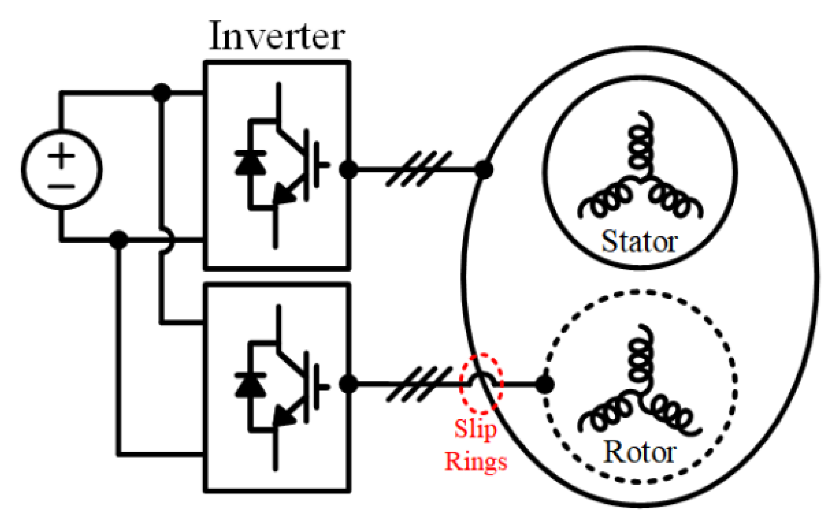
Unlike a structure in which two inverters are applied to the stator side, in a double inverter-fed wound motor (DIFWM), an additional inverter is connected to the rotor windings through slip rings and brushes. Both side inverters provide power for driving the motor [
10,
11,
12,
13,
14,
15,
16,
17,
18,
19,
20,
21,
22,
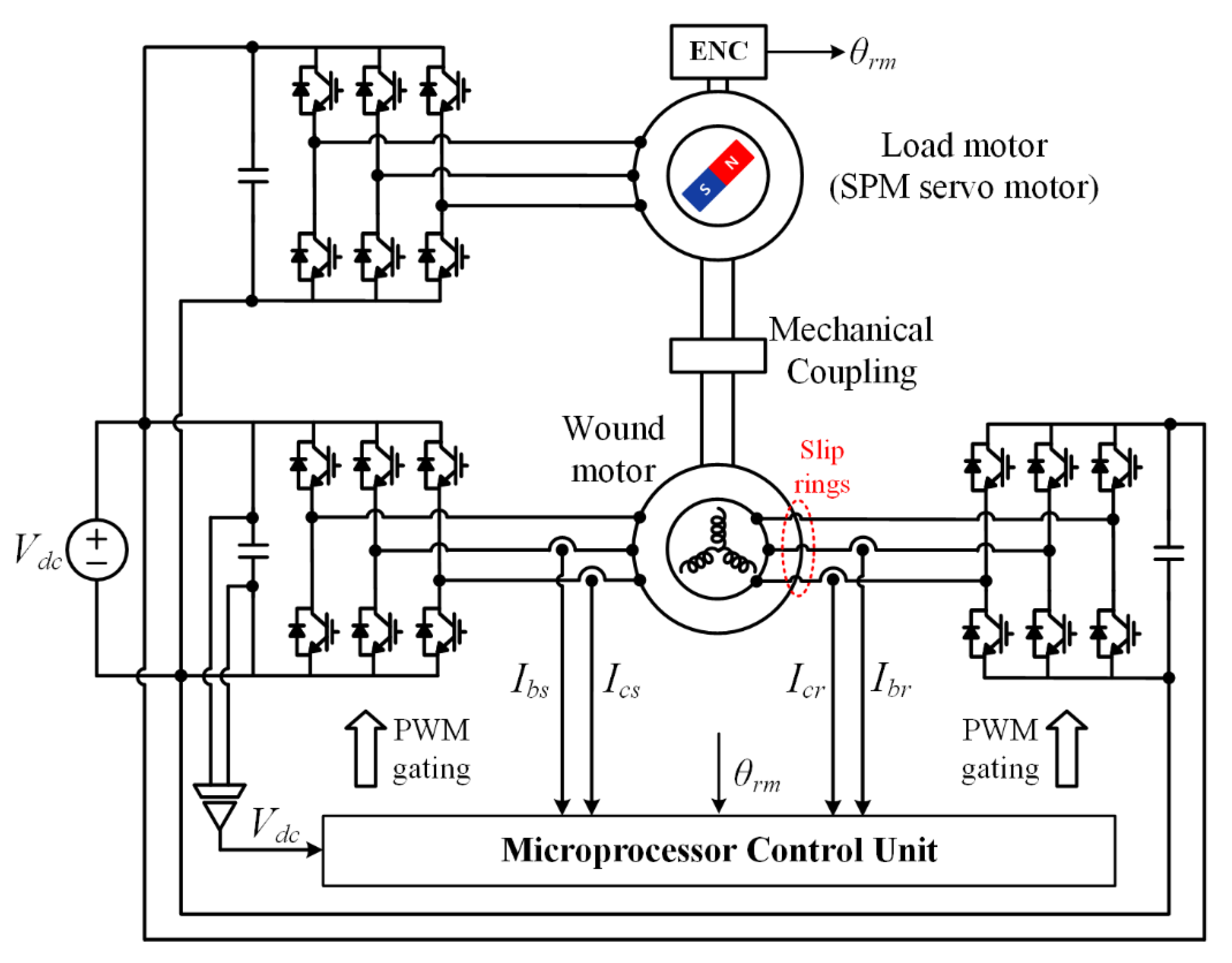
23]. The structure of the DIFWM is shown in
Figure 1. When the same DC link voltage is applied to both inverters, it is possible to drive up to 2 p.u. [
19,
20,
21,
22,
23]. Power distribution between two inverters is possible without additional elements, which is an advantage in high-power systems. In addition, since the stator side current as well as the rotor side current are controlled, there is an additional degree of freedom in control compared to the conventional singly-fed motor drive system, such as IM. Using this additional degree of freedom in control, sensorless operation is possible in all operating areas including stationary conditions without high-frequency voltage injection [
19,
20], and fault-tolerant operation against failure of one inverter is also possible [
21].
This article deals with current control-based fast flux and torque control in a DIFWM. The proposed method enables torque control with high dynamic characteristics in a situation where the flux is changed for high-efficiency operation [
24,
25,
26]. In the conventional IM, the steady-state flux is regulated only by the stator current, but if there is a change in the flux, the rotor current that suppresses the change of the flux delays the flux control in proportion to the rotor time constant. This delay affects the dynamic performance of torque control. Therefore, although there is efficient operation to adjust the magnitude of the flux according to the torque, the flux is fixed to the rated value for the high dynamic performance of torque control. To improve the performance of the variable flux-based control, additional flux controllers have been proposed [
27,
28,
29], but there is a limitation due to the bandwidth of the flux estimator. Moreover, fast flux variation can cause an excessive flux component stator current.
On the contrary, in a DIFWM, since the inverter is applied to not only the stator side but also the rotor side, the magnetic flux can be simply calculated from the measured currents on the stator and rotor sides. In addition, since inverters applied to both sides control each current, magnetic flux can be quickly controlled. However, since coupling interference exists between the stator and rotor sides, a control method that includes decoupling operation is required.
After this introduction section, this article is organized as follows for each section.
Section 2 simply reviews the conventional rotor flux-oriented vector control of a DIFWM for an easy explanation of the proposed method.
Section 3 covers the proposed current controller of a DIFWM, while
Section 4 and
Section 5 verify the feasibility of the proposed method through the simulation and experimental results with respect to a 1.7 kW DIFWM drive system.
3. Proposed Current Controller Design of a DIFWM
In a three-phase AC motor vector control system that applies a synchronous coordinate system, coupling interference exists between the
d- and
q-axes. In order to eliminate coupling interference, the feed-forwarding method or complex control can be applied as a decoupling control [
30,
31]. However, a DIFWM additionally includes coupling interference between the stator and rotor currents as shown in the last terms of (1) and (3). To eliminate this coupling interference between the stator and rotor sides, the open-loop control method can be applied to the rotor-side controller [
19,
20] or the rotor-side current controller can be applied only to the proportional (P) controller, and the PI gains of the stator-side current controller can be determined considering the P gain of the rotor-side controller [
32]. However, these methods allow a steady-state error of the rotor current, and because the characteristics of the current controls on both sides are different, the performance of the rotor flux control cannot be guaranteed.
3.1. PI Gain Set-Up of Current Controllers
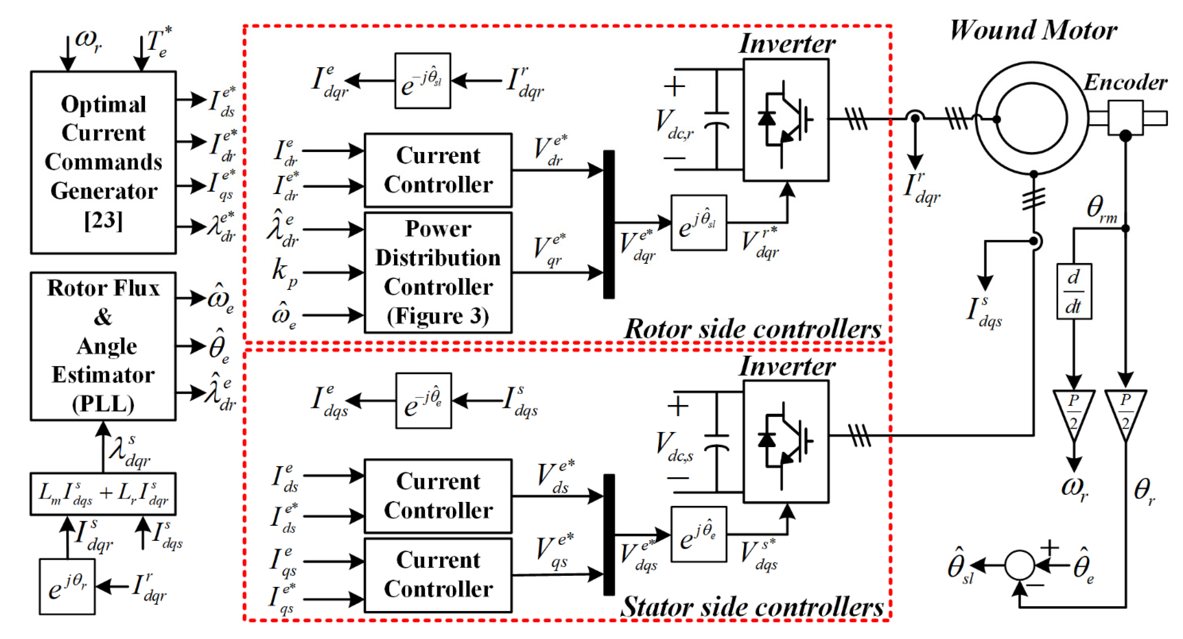
The proposed method applies the three PI controllers for the current controls as in
Figure 4, as well as the feed-forwarding method to suppress coupling interference, not only between the stator
d- and
q-axes but also between the stator and rotor d-axes. These integral controllers basically ensure zero steady-state errors. The PI gains of the three controllers are determined for the same dynamic characteristics. Therefore, the proposed current control method of a DIFWM guarantees the same dynamic performance of rotor flux and torque control as the designed current controller.
The three current controllers, including the feed-forwarding compensation components of the three current controllers, can be represented as follows
where
Kps and
Kis denote the proportional and integral gains of the stator
d-axis and
q-axis current controllers, respectively;
Kpr and
Kir are the proportional and integral gains of the rotor
d-axis current controller, respectively;
Vds_ffe,
Vqs_ffe, and
Vdr_ffe correspond to the feed-forwarding compensation components of the stator d-axis, the stator q-axis, and rotor
d-axis current controllers, respectively. The coupling interference components can be obtained from the phase voltage equations of (1)–(3), and each feed-forwarding compensation value to remove the coupling interferences between the three current controllers is set as follows
Assuming that the feed-forwarding components of (14)–(16) are ideal and the coupling interferences are eliminated by
Vds_ffe,
Vqs_ffe, and
Vdr_ffe, the transfer functions of the current controllers are designed to be a first-order low-pass filter (LPF) with the same bandwidth. Analysis of the feed-forwarding components is covered in the following section. For the closed-loop transfer function of the first-order LPF, the current controller gains of the stator side can be designed as follows
where
denotes the cutoff frequency of the stator-side current controllers.
The gain set-up of (17) and (18) equals the case of the conventional IM vector control system [
29]. When the gain values of the stator-side current controllers are set as in (17) and (18), the closed-loop transfer function is as follows
In the rotor voltage Equation (3), if the forward compensation value in (16) is excluded, only the voltage drop term due to resistance remains. Therefore, the closed-loop transfer function of the rotor
d-axis current controller according to
Kpr and
Kir is as follows
As in (20), the closed-loop transfer function of the rotor-side current controller is determined by the sum of the first-order LPF and the high-pass filter (HPF). The cutoff frequencies of the LPF and HPF are set to the same value as follows
where
ωcc_r refers to the cutoff frequency of the rotor
d-axis current controller. If this cutoff frequency is set equal to
ωcc_s and the gain value of the HPF is set to enough of a small value to be neglected, the transfer function of (20) is approximated to (19). At this time, if the gain value of the HPF is set to 1/
nr, the proportional and integral gain values of the rotor current controller can, respectively, be set as follows
When nr is set to a value of 100 or more, as confirmed through simulation and experiment, almost the same characteristics and the stable operation are shown. The current controllers of the stator and rotor sides can be designed with a transfer function of the first-order LPF having the same cutoff frequency, ωcc. Since the rotor flux is determined by the stator and rotor d-axis currents as in (5), the rotor flux controller also has the same closed-loop transfer function of the first-order LPF with the same cutoff frequency, ωcc. However, this current controller design is accomplished under the assumption that the coupling interferences are eliminated by the feed-forwarding components of (14)–(16).
3.2. Feed-Forwarding Compensation Components
The feed-forwarding components of (14)–(16) can be classified into two types. The first is the voltage drop component proportional to the synchronization frequency, which causes the coupling interferences between the stator
d-axis and
q-axis current controllers. Under the assumption that the change of the mechanical rotation speed is sufficiently slower than the bandwidth of the current controller, these components can be obtained from the measured currents and speed, which is usually applied in the case of IM [
29].
The second is a derivative term of the rotor flux, which is included in (1) and (3). This value increases when the rotor flux is adjusted according to the torque for efficient operation in the operation below the base speed. Compensation of this derivative term requires knowing the value of the rotor flux in the next sampling. The predictive control concept to estimate the next sampling value or the deadbeat control to apply the reference value as the next sampling value can be introduced [
28]. However, these controls are sensitive to errors of the motor parameters and any noises.
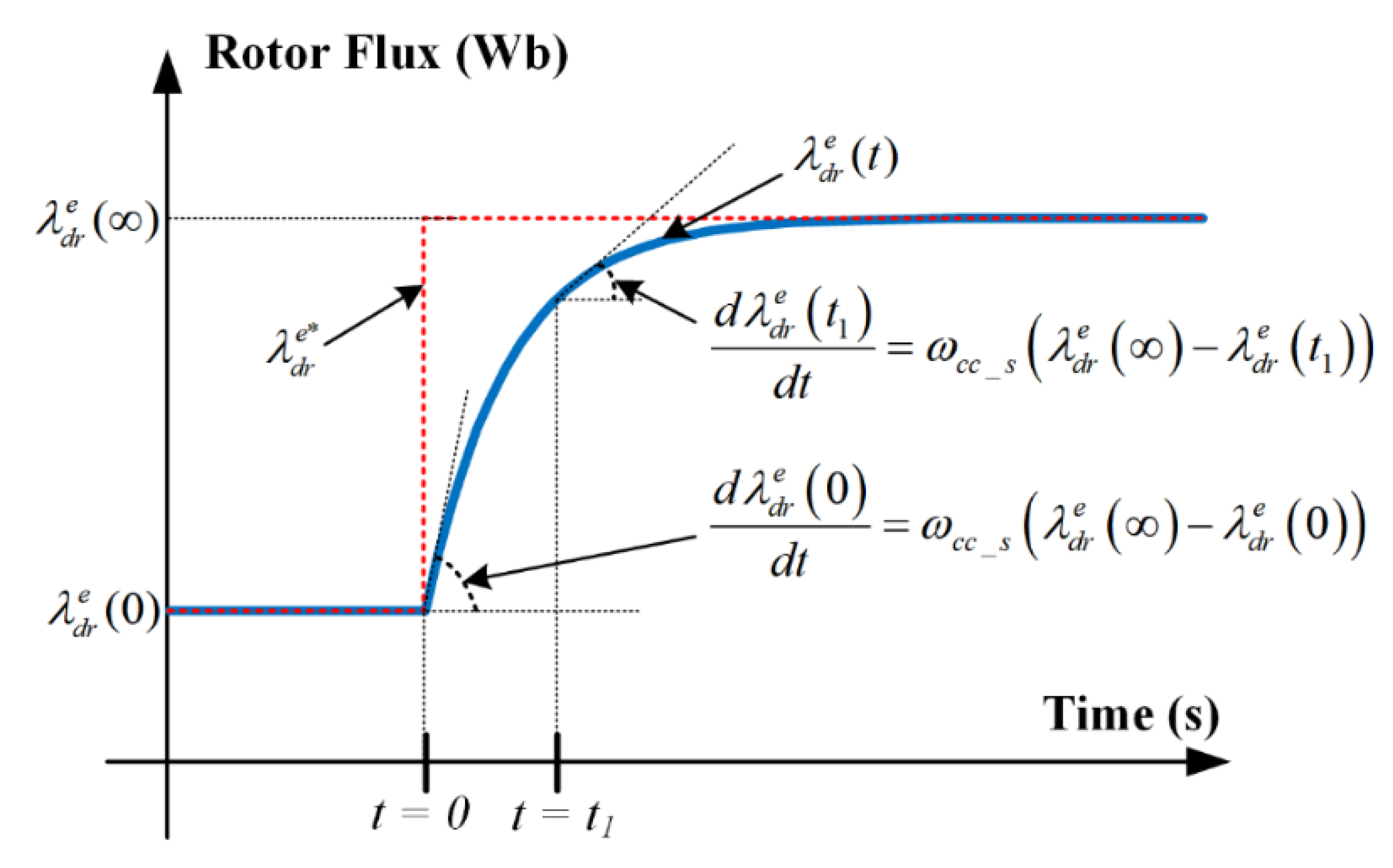
In the proposed current controller, since the transfer function of the rotor flux control is determined as the first-order low-pass filter according to the design of the current controller, the rotor flux changes are determined according to the transfer function of the current controller. Therefore, for a given stepwise rotor flux reference change, the change of the rotor flux appears as in
Figure 5, and the derivative value of the rotor flux is determined by the bandwidth of the current controller as follows
The result of (25) is used to calculate the derivative term of rotor flux in the proposed method, which eliminates the coupling interferences between the stator and rotor d-axis current controllers. When the rotor flux is changed according to the torque command for high-efficiency operation, the rotor flux and torque controls have the same dynamic performance as the current controller.
The derivative term calculation method presented in (25) can be interpreted as a decoupling controller between the stator and rotor d-axes. Since the rotor flux is determined as (5), (25) can be expressed as follows
That is, the derivative term of the rotor flux at (25) can be interpreted as an additional P controller for decoupling between the stator and rotor d-axis current controllers. However, in this article, (25) is regarded as a feed-forwarding compensation term and applied for more straightforward analysis.
4. Simulation Results
To verify the feasibility of the proposed decoupling current control method for the DIFWM, simulation tests using PLECS environment were carried out. The DIFWM was basically operated in the torque control mode as shown in
Figure 4, where the rotating speed is fixed by the desired value. As shown in
Figure 4, by estimating the amplitude, angle, and synchronous frequency of the rotor flux from the measured stator and rotor currents, the same control conditions as in the experiment were applied. The motor and inverter parameters of the DIFWM applied to the simulation tests are specified in
Table 1. The actual turns ratio was
Ns/Nr = 1.375:1, but, for the convenience of analysis, all values referring to the stator side were applied, and the simulation results were also expressed as values referring to the stator side. In addition, for the MCL operation of
Figure 4, the rotor flux was set according to the torque command as follows [
23]:
Using (27), the references of the stator and rotor
d-axis currents and the stator
q-axis current are determined as in the following equations
Here, the rotor flux is limited by the rated rotor flux condition. Hence, the optimized rotor flux is proportional to the square root of the torque around a low torque region, but the rotor flux is fixed into the rated rotor flux at a high torque region.
For the comparative study with the conventional control methods, the simulation tests were performed in three control modes. In the first control mode, no feed-forwarding compensation term was applied [
23]. As shown in
Figure 4, only three PI controllers were used and the PI gains were set as (17), (18), (23), and (24).
In the second control mode, the voltage drop components proportional to the synchronous frequency were compensated [
30,
31].
The last one compensates all coupling interferences of the DIFWM, which corresponds to the proposed method as in (14)–(16).
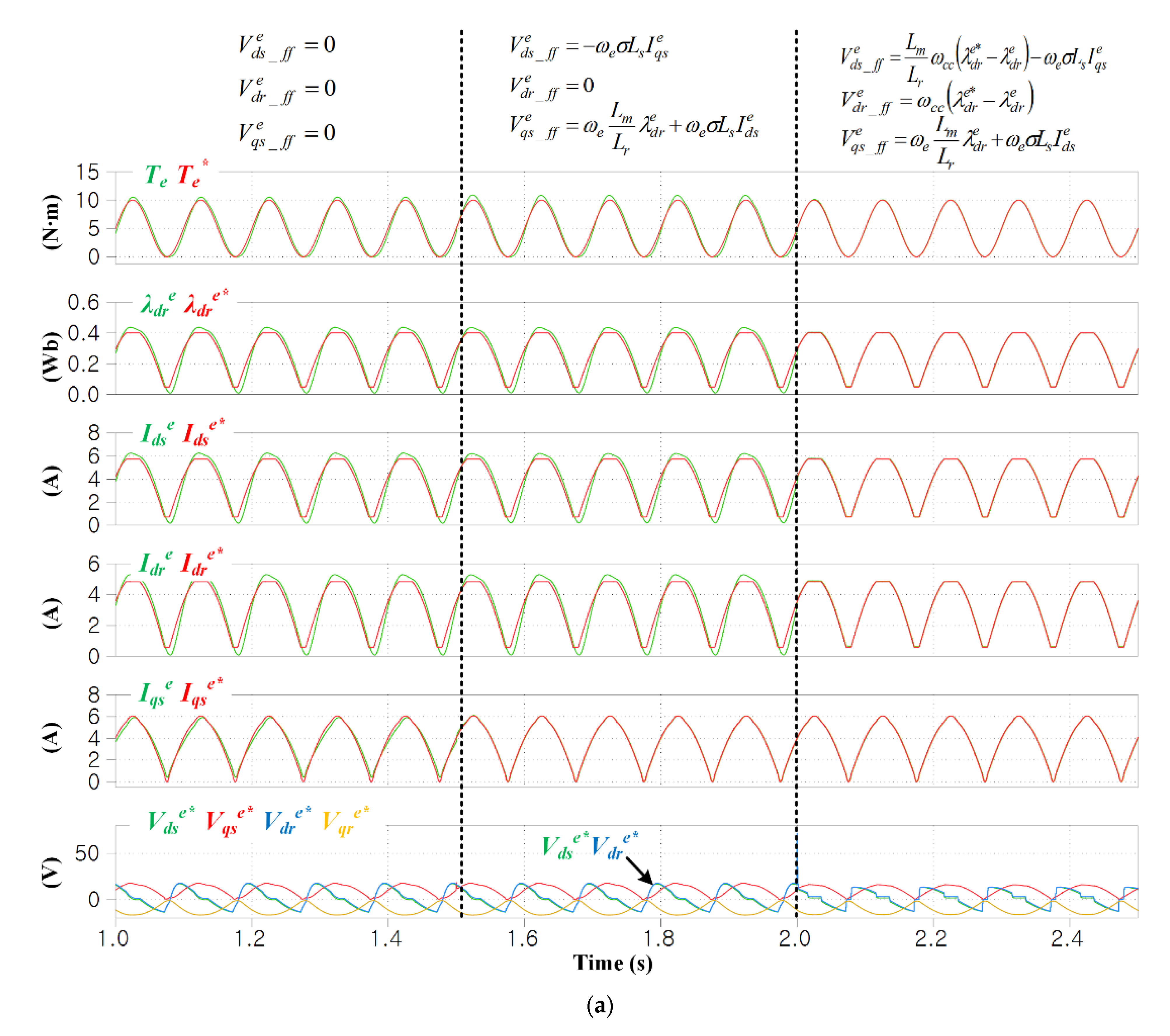
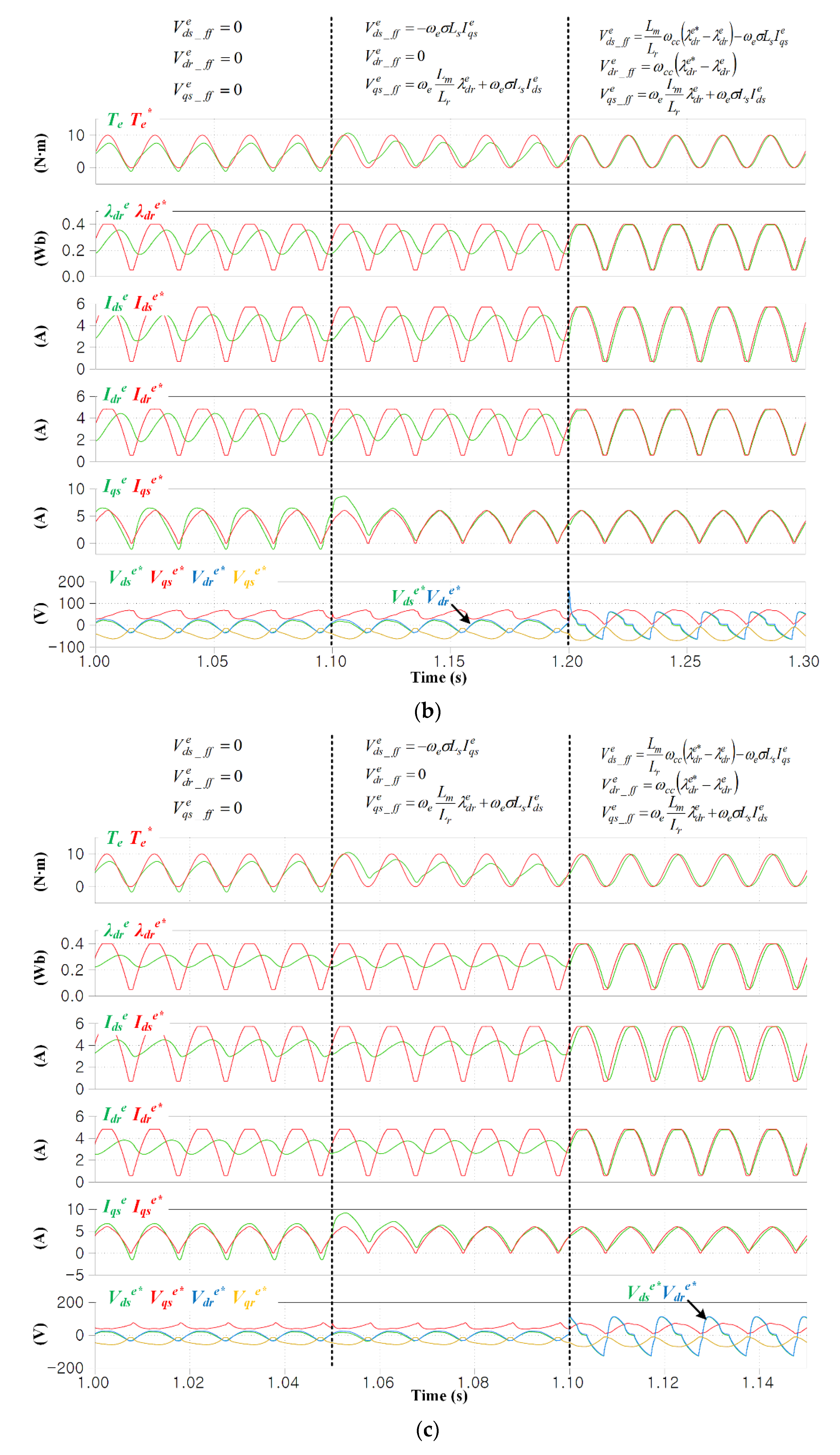
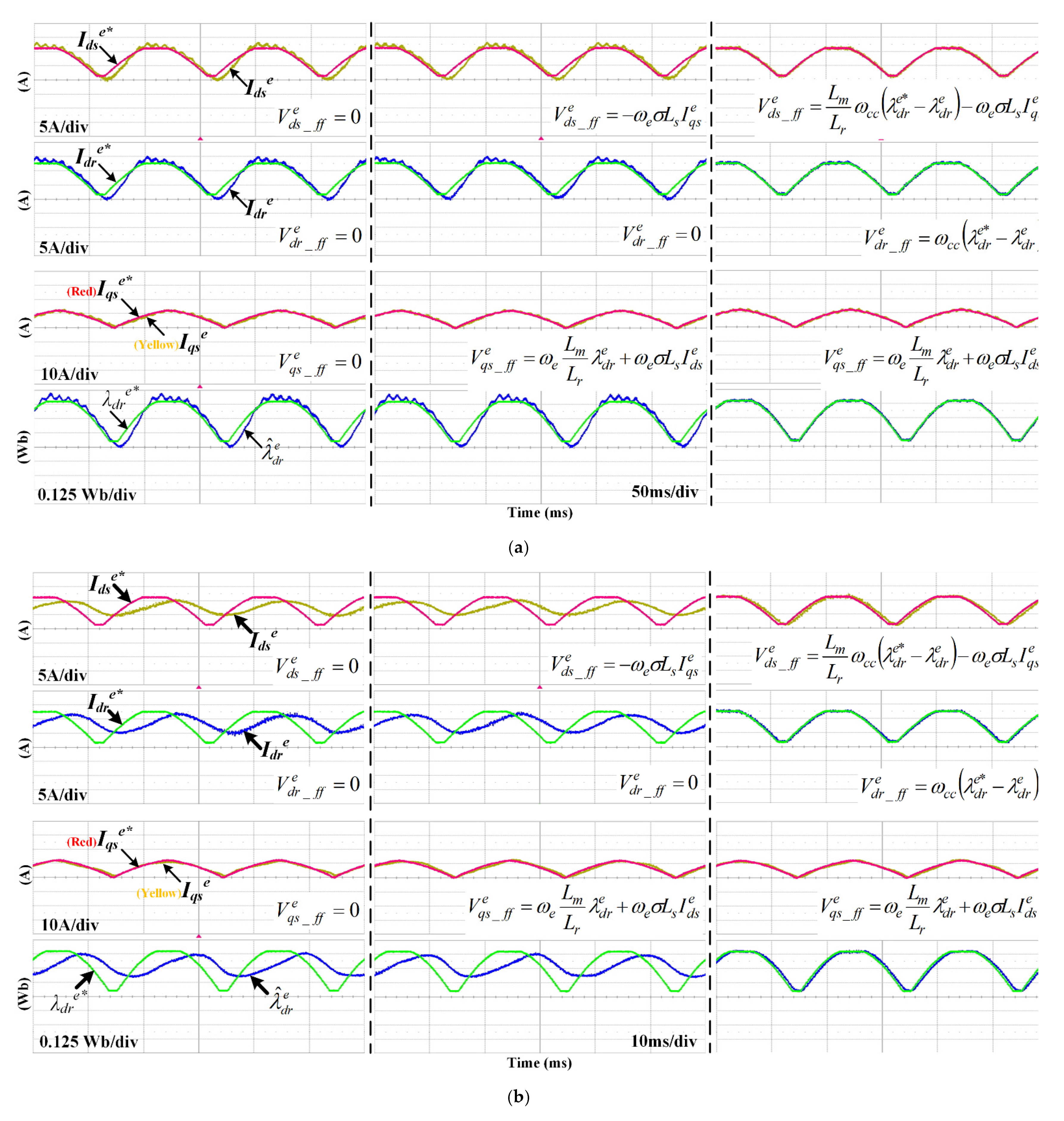
Figure 6a–c shows the performance of the torque, rotor flux, and current control with the voltage references on both sides. Here, the operating speed was fixed to 200 r/min, which corresponds to a low speed below the rated speed, and the cutoff frequency
and
nr were set to 300 Hz and 100, respectively. In
Figure 6a, the torque command was set to swing from 0 to 10 N∙m in a sinusoidal manner of 10 Hz. Here, considering the rated rotor flux condition of (31), the
d-axis stator and rotor currents were limited in the torque region of approximately 9 N∙m or more. The simulation consisted of the three control modes mentioned above. First, the stator
q-axis current was well controlled in all control modes according to the designed current control bandwidth. However, the stator and rotor
d-axis currents had errors and delays, except for the third case of the proposed method. Although the components proportional to the synchronous frequency were compensated in the second control mode, the results of the
d-axis currents were significantly different from the proposed method. This means that when the rotor flux is adjusted according to the torque command for the MCL operation, the derivative term of the rotor flux component acts as a major coupling component. Therefore, if this derivative component is not compensated, the performance of not only the rotor flux control but also the torque control is greatly degraded, as shown in
Figure 6a. On the contrary, when the proposed method was applied, the current, rotor flux, and torque were controlled with the designed bandwidth. The bottom waveforms show that the synchronous voltage commands had different patterns with the two conventional control modes. Especially, the pattern changes of the
d-axis stator and rotor voltages to compensate for the derivative term of the rotor flux are evident.
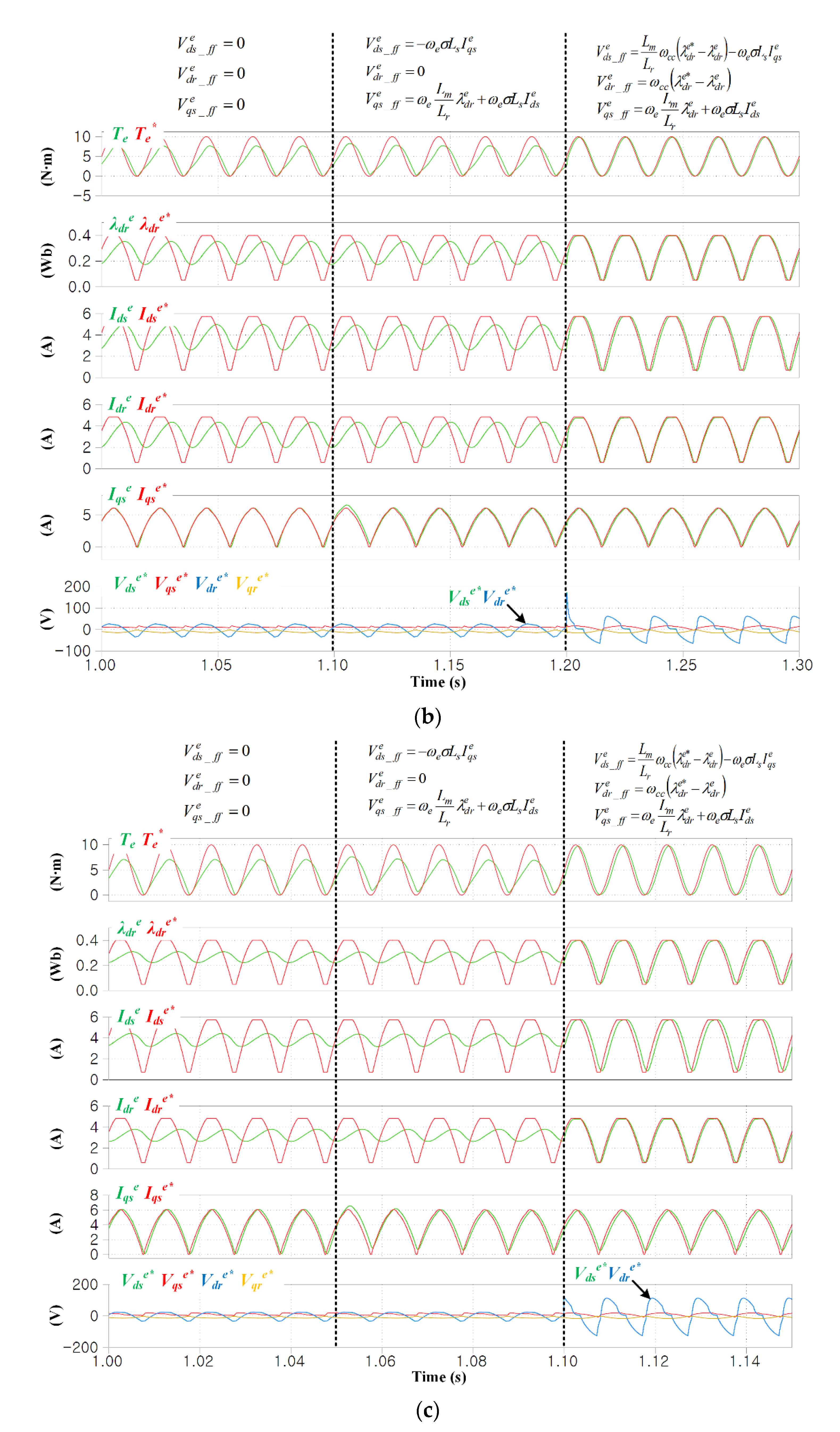
In
Figure 6b,c, the frequency of the torque command is increased to 50 and 100 Hz, respectively. In the conventional control modes of (32) and (33), the control performance is significantly reduced compared to
Figure 6a because of the increased frequency of the torque command. By compensating all coupling components by the proposed method, the current, rotor flux, and torque controls operate as designed. As the torque fluctuation frequency increases, the changes in the
d-axis stator and rotor voltage commands according to the proposed method appear more clearly than in
Figure 6a. A little delay occurs in the part of the proposed method in
Figure 6c because the current controller bandwidth is set to 300 Hz. This delay can be reduced or eliminated by increasing the current controller bandwidth.
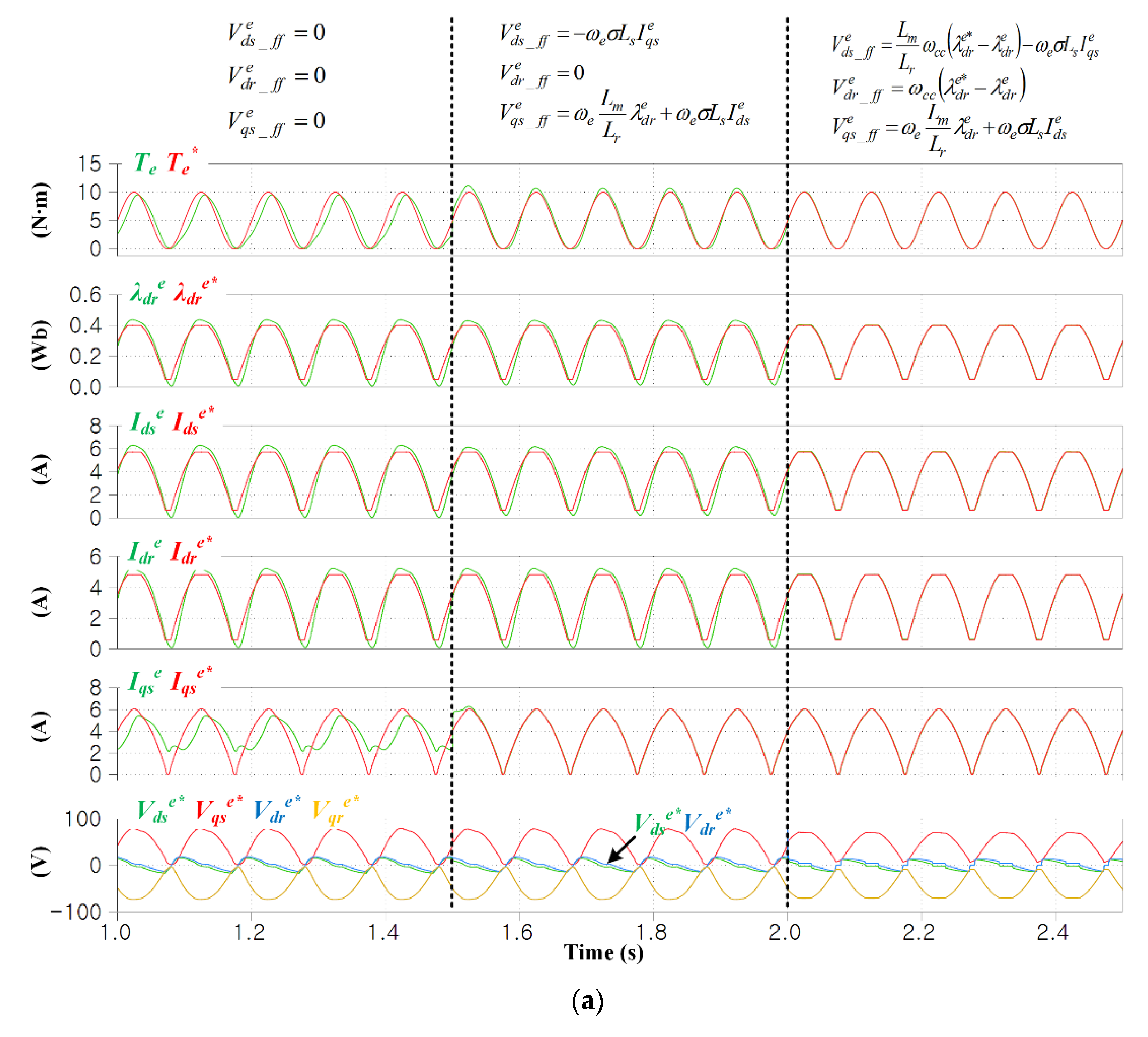
In
Figure 7a–c, all simulation conditions are the same as with
Figure 6a–c, respectively, except the rotating speed at which the rated speed (1055 r/min) was applied. Compared with the case of the previous low-speed operation, the effects applying the compensation components of (33) can be confirmed at the
q-axis stator current control. In
Figure 7a–c, as the second control mode is applied, the
q-axis control performance is greatly improved, but there is little change in the control performance of the
d-axis stator and rotor currents. On the other hand, as the proposed method is applied, the
d-axis stator and rotor currents are controlled according to the designed bandwidth as in the simulation tests of the previous low-speed operation.
5. Experimental Results
Experimental verifications were carried out on the wound machine and inverters, of which the specifications are shown in
Table 1.
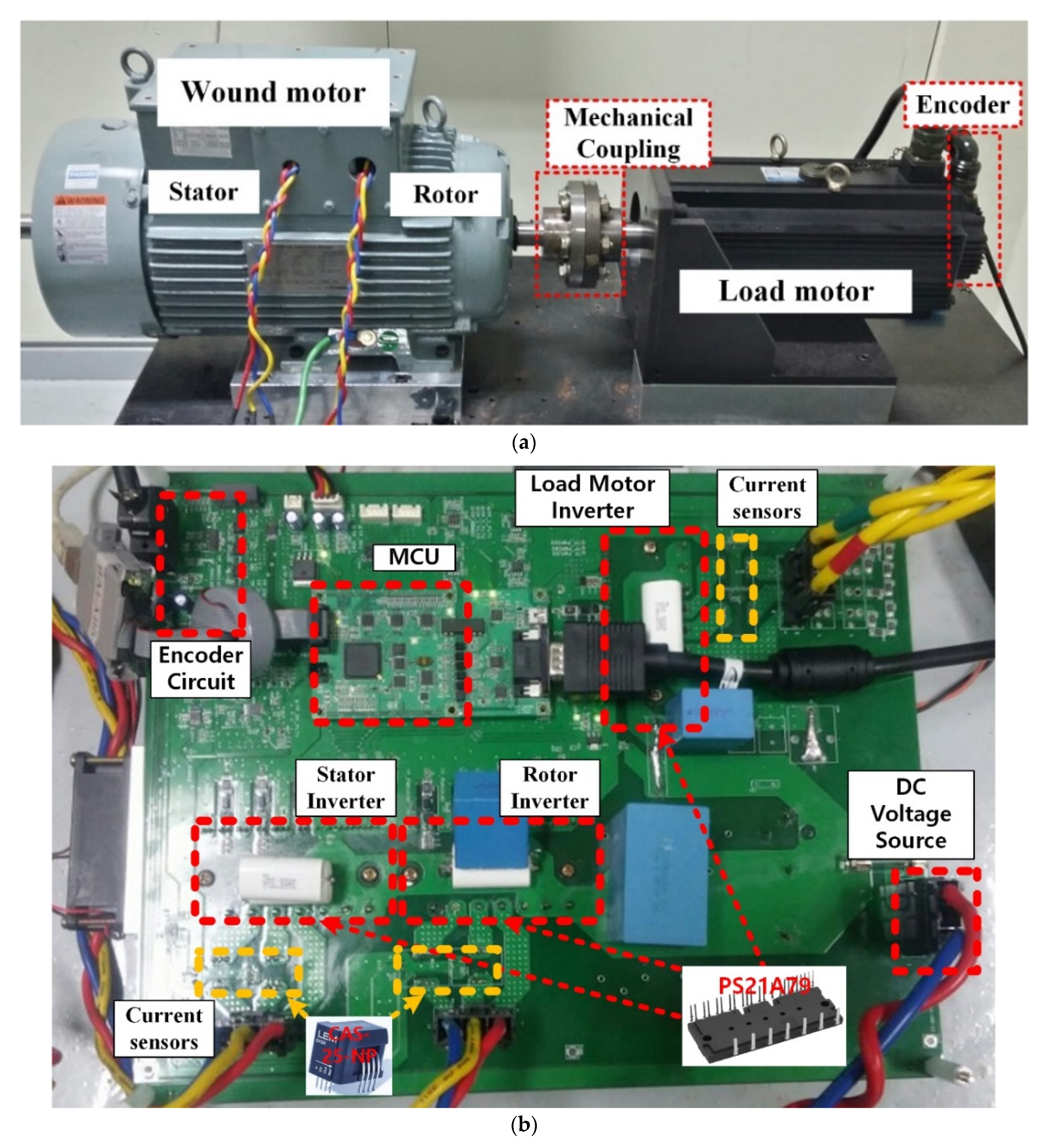
Figure 8 shows a diagram of the experimental set-up, where a surface mounted permanent magnet (SPM) servo motor was coupled as a load motor through a mechanical coupling. Also, an incremental encoder of 2000 pulse-per-revolution equipped to the SPM servo motor was used for the filed orientation as in
Figure 4. The DIFWM and the load motor were operated in the torque control mode and the speed control mode, respectively.
Figure 9a,b show photographs of the dynamo set and the inverter set used in the experiments. Three intelligent power modules (PS21A79) were used as inverters for the DIFWM and the load motor, and all inverters shared the same dc link sourced by the external dc power as shown in
Figure 8. Additionally, each inverter had two current hall sensors (CAS-25-NP) and the measured currents were used for not only the feed-back control but also the estimation of the rotor flux as in
Figure 4. The inverters and current sensors were equipped to the bottom side of the inverter board.
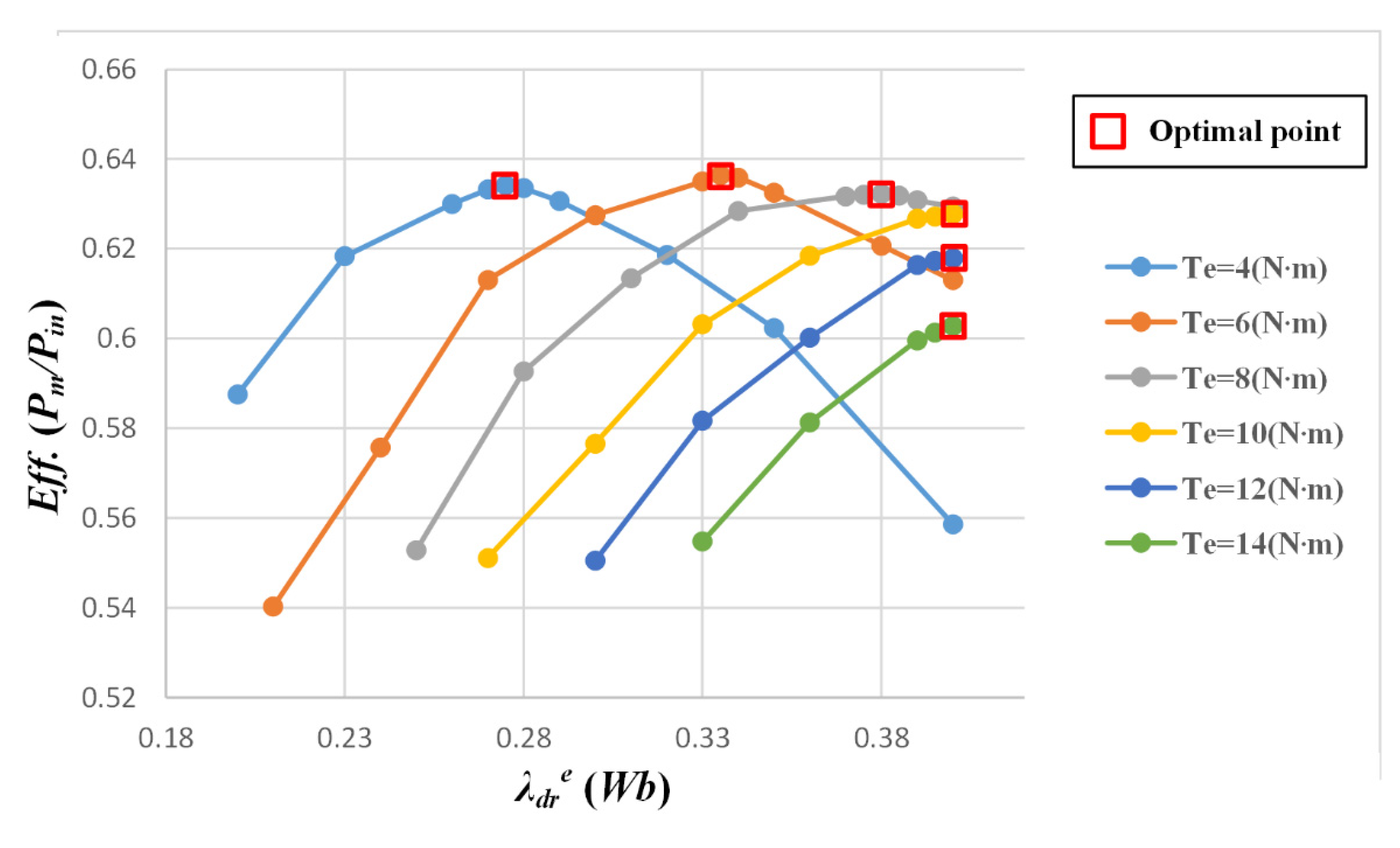
Before confirming the performance of the proposed method, the input power and efficiency according to the varied rotor flux were checked.
Figure 10 shows the efficiency according to the rotor flux, where the operation speed is fixed to 200 r/min. At torques above 10 N∙m, the optimal rotor flux is fixed to the rated rotor flux because the rotor flux is limited by the rated rotor flux. On the contrary, at torques below 10 N∙m, the optimal rotor flux value decreases as the torque decreases, which means that the rotor flux variation contributes the efficiency improvement [
23].
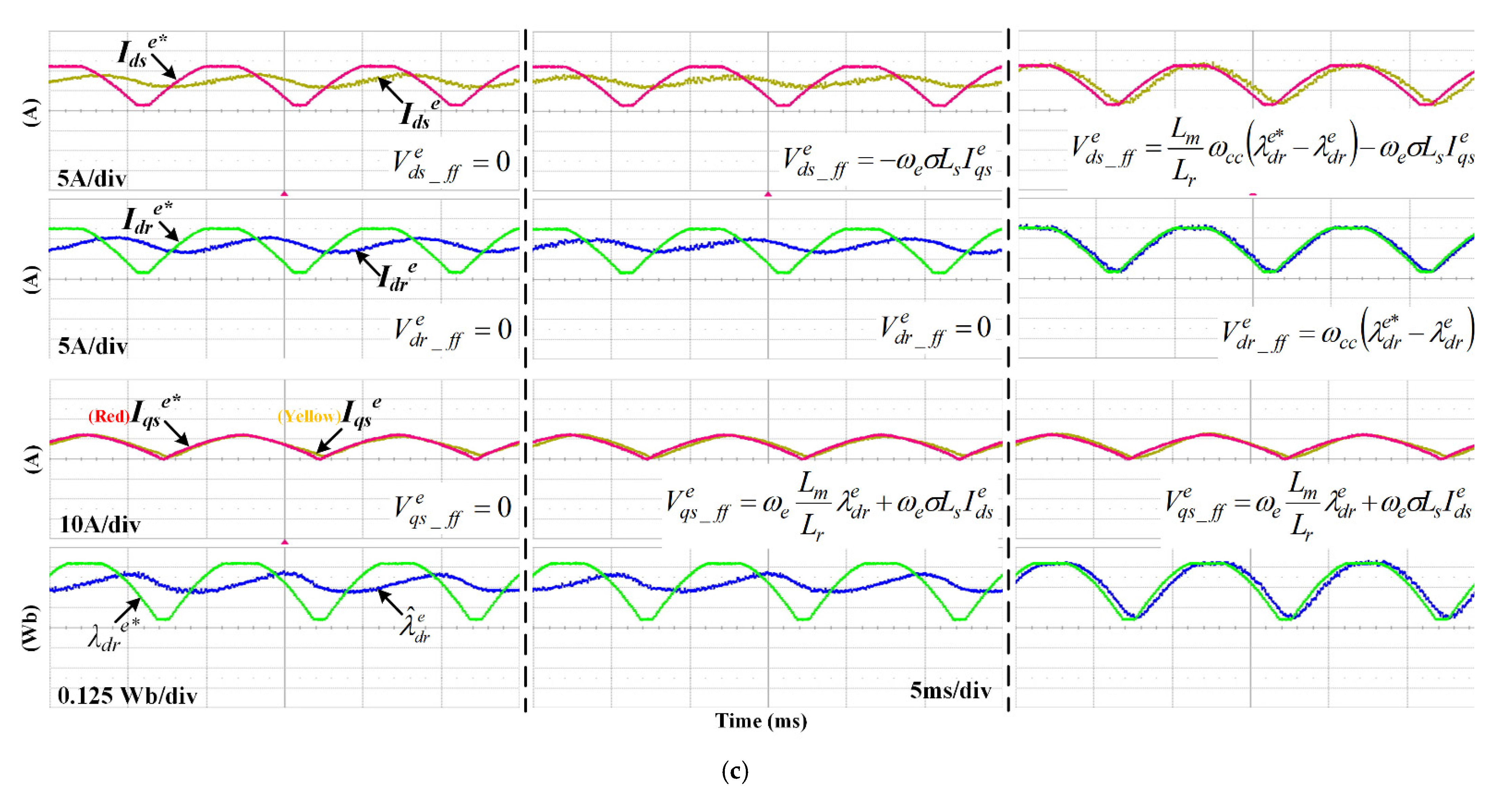
Figure 11a–c show the
d-axis currents on both sides, the stator
q-axis current, and the rotor flux controls when the torque command swings from 0 to 10 N∙m. The experimental conditions are identical to the simulations in
Figure 6a–c, except that the estimated rotor flux values are presented in the experiments because the magnetic flux is not directly measured but estimated. The current and rotor flux controls were performed in the three control modes. At a fixed speed of 200 r/min, the torque command was sinusoidally changed by 10, 50, and 100 Hz, and the results are shown in
Figure 11a–c, respectively. As in the simulation results of
Figure 6a–c, the control performance of the
q-axis current is guaranteed to some extent without any compensation due to the low speed (200 r/min), but the
d-axis currents are affected and delayed by the change of the rotor flux. Although the cutoff frequency of the current controller was set to 300 Hz, the
d-axis currents could not be properly controlled even with a torque variation of 10 Hz, and this situation did not change even when only the components proportional to the synchronous frequency were compensated. On the contrary, when the derivative term of the rotor flux was compensated, all three currents operated according to the designed cutoff frequency of 300 Hz. All these experimental results are the same as the simulation results in
Figure 6a–c. In
Figure 11a, the small harmonic ripple of the current is the effect of the 12th harmonic of the motor.
6. Conclusions
In a DIFWM, although the additional current controller of the rotor side is applied and provides the additional controllability, the decoupling control using the additional controllability has not been presented. This article proposed the decoupling current control method of a DIFWM using the additional controllability and considering all coupling components for fast flux and torque control. To eliminate the coupling effects, the feed-forwarding technique is applied, where the derivative term of the rotor flux is implemented under the assumption that the rotor flux is regulated by the designed bandwidth of the current controller. From the simulation and experimental results, the performance of the proposed method was verified. If the bandwidth of the current controller is designed to be 300 Hz, the rotor flux and torque control work well for fluctuations in torque command up to 100 Hz.
The DIFWM has various merits of the fault tolerance operation, the sensorless operation without high-frequency injection, and the power distribution operation of stator and rotor inverters, which are useful in the applications that require safety, high power, and high-speed operation such as electric vehicles. Additionally, through the proposed current control, the DIFWM can be controlled with high efficiency through variable rotor flux mode without compromising the dynamic performance of torque control, so it can be utilized in applications requiring high dynamic performance and high efficiency. Therefore, this study paved the way to the extended applications of the DIFWM. However, since this study dealt with only the current control in the linear modulation region, the proposed decoupling control above the rated speed may be limited. Thus, future studies can include the overmodulation method considering the voltage limit of the two inverters in DIFWM and the performance verification of decoupling control in overmodulation operation.


