Article

Robust Predictive Control Scheme for Permanent-Magnet Synchronous Generators Based Modern Wind Turbines

1
Electrical Engineering Department, Faculty of Engineering, Assiut University, Assiut 71516, Egypt
2
Institute for Electrical Drive Systems and Power Electronics (EAL), Technische Universität München (TUM), 80333 Munich, Germany
3
Department of Electrical Engineering and Information Technology, Munich University of Applied Sciences, 80335 München, Germany
*
Author to whom correspondence should be addressed.
Electronics 2021, 10(13), 1596; https://doi.org/10.3390/electronics10131596
Submission received: 28 May 2021 / Revised: 28 June 2021 / Accepted: 30 June 2021 / Published: 2 July 2021

Abstract

:
In this article, a deadbeat predictive control (DB-PC) strategy for permanent-magnet synchronous generators (PMSGs)-based modern wind turbines is proposed. The main advantages of the DB-PC technique are its excellent dynamics and its constant switching frequency. However, the main idea of DB-PC is obtaining the actuation voltage for the next sample from the mathematical model of the generator. Therefore, the DB-PC is highly sensitive to mismatches in the parameters of the PMSG. In order to obviate this problem, a disturbance estimator (extended Kalman filter (EKF)) is employed in this work to enhance the robustness of the proposed DB-PC scheme by estimating the total disturbance due to parameter mismatches and adding it to the calculation of the actuation voltage. Furthermore, the same EKF observe the rotor speed and position of the PMSG, i.e., mechanical sensors are not required. Moreover, the EKF is able to reduce the harmonic distortion in the stator currents of the PMSG. The proposed DB-PC strategy is implemented in the laboratory. The experimental results proved the superiority of the proposed DB-PC strategy over the traditional DB-PC technique.

1. Introduction

Currently, the whole world is facing the problem of global warming. The high emission of carbon-dioxide CO 2 is one of the reasons for this phenomena. Therefore, the generation of electricity by burning fossil fuels must be stopped. The alternative solution is the use of clean and renewable energy systems, such as wind energy, photovoltaic arrays, wave energy, etc. In fact, the installation of wind turbines has remarkably increased in most of the countries around the world [1,2,3,4]. The first version of wind turbines was of a fixed-speed with an induction generator. However, due to its disadvantages, such as lower efficiency, need for reactive power, and higher sensitivity to voltage dips or faults in the grid, modern wind turbines are variable-speed ones [5,6,7].
In the current wind market, two generators are the most used: the doubly-fed induction generator (DFIG) and the permanent-magnet synchronous generator (PMSG) [1,2,3]. In the DFIG topology, a reduced-scale of the back-to-back (BtB) power electronics converter is utilized, which reduces the cost of the wind generation system. However, the variation of the shaft speed is limited to ± 30 % around the synchronous speed [8]. Furthermore, the stator of this DFIG is tied directly to the point of common coupling (i.e., the grid). Accordingly, the wind generation system with DFIG is sensitive to abnormal conditions in the grid. In the PMSG topology, the stator terminals are interfaced with the grid, using a full-scale BtB power electronics converter [9], i.e., the cost of the BtB converter is higher than in the case of DFIGs. However, due to this decoupling between the generator terminals and grid, the wind generation system with PMSG offers better fault ride through (FRT) capability than the DFIGs. Furthermore, the range of shaft speed variations is bigger than in the case of DFIGs. Finally, the PMSG is directly coupled to the wind turbine, i.e., no gear-box is required, like in case of the DFIG.
Usually, the field-oriented control (FOC) with proportional-integrators (PIs) is used to control the PMSG-based modern wind turbines [10]. The PI controllers produce good steady-state and transient response. However, the selection of the PI parameters is not an easy task. Furthermore, in the case of achieving quick dynamic performance with the PI controllers, very high overshoot is produced. Therefore, the researchers proposed several other control techniques for electrical machines, such as sliding-mode, fuzzy logic, predictive control, etc.
In the last few years, predictive control techniques have been widely applied for power electronics circuits, electrical machines, micro-grids, and others. The well-known strategies of the predictive control are as follows: continuous-set predictive control (CS-PC) [11,12], finite-set predictive control (FS-PC) [13,14], and deadbeat predictive control (DB-PC) [15,16]. The CS-PC is characterized by its constant switching frequency, non-linearity, ability to include constraints, etc. However, due to the very high calculation burden, part of the CS-PC algorithm is implemented offline, which is not preferred for power electronics circuits and electrical machines. The algorithm of the FS-PC can be completely online implemented due to the use of only the discrete states of the power converter. Furthermore, constraints and non-linearities can be considered in the design of the FS-PC. However, the steady-state response of the FS-PC is not good, due to the application of only one voltage vector per sample. Furthermore, the switching frequency of the FS-PC is variable.
The DB-PC is featured by its fixed switching frequency, due to the use of a modulator to generate the switching signals of the power converter. Moreover, its steady-state and dynamic performance are excellent. The basic idea of the DB-PC is calculation of the reference voltage vector from the machine model and the reference variables [15,16]. Therefore, it is sensitive to any mismatches in the model parameters of the machine under control. To cope with this problem, online observation of the machine’s parameters improves the robustness of the DB-PC. In [17], an extended Kalman filter (EKF) is employed to estimate the stator inductance of the PMSG. However, the stator resistance and permanent-magnet flux linkage are assumed to be constants, which is not true in practice. In [18], the model reference adaptive system (MRAS) observer is utilized to estimate the model inductance of an active front end (AFE) rectifier. However, the model resistance is defined as a constant. Online and offline estimation methods for the stator resistance, stator inductance and rotor flux linkage of an IPM motor are proposed in [19]. However, offline methods are not preferred for electrical drive systems. In [20], a new method is proposed to estimate the stator resistance and inductance of a PMSM. However, the permanent-magnet flux linkage is considered to be a constant. In [21], a novel online inductance estimation method is proposed for grid-connected photovoltaic (PV) inverters. However, the model resistance is not estimated.
In the above online estimation methods, the effects of any un-modeled dynamics or non-linearities are always neglected. Therefore, the other solution to improve the robustness of the DB-PC technique is observing the total disturbance caused by parameter variations and including this total disturbance in the controller design. In [22], the time-delay control approach is employed to estimate the total disturbance for PMSGs. The robustness of the used DB-PC in this work (i.e., [22]) is significantly improved in comparison with the classical DB-PC. However, low-pass filters (LPFs) to filter the signals of the total disturbances before sending them to the controller are required. LPFs change the amplitude and phase of the original signals. In [23], a sliding mode observer is presented for observing those total disturbances. However, the chattering phenomena of the sliding mode observer is the main problem. An interval-varying multi-innovation least squares algorithm is presented in [24]. However, the complexity of the whole control scheme is increased. In [25,26], a new compensation method to avoid the effect of parameter variations on the DB-PC is presented. This method is based on adding integral part to the main controller. However, selection of the integrator gain is not an easy task.
Normally, the control system of the PMSG is implemented in the rotating-reference frame d q . Therefore, measurement of the rotor position and speed is essential [27]. Mechanical sensors, such as incremental encoders or speed transducers, can do this job. However, the failure rate of these mechanical sensors is significantly higher than the electrical ones [28]. Therefore, in the case of failure, the whole control of the PMSG does not work, i.e., no active and reactive power can be injected by this unit, which might affect the grid. Accordingly, estimation of the rotor speed and position of the PMSG is highly required to enhance the reliability of the whole system [27,28].
In this paper, a robust deadbeat predictive control (DB-PC) for permanent-magnet synchronous generators (PMSGs) without mechanical sensors is proposed. The DB-PC algorithm computes the actuation voltage based on the mathematical model of the PMSG and reference variables. Therefore, any variations in the parameters of the PMSG will highly deteriorate the performance of the controller. Hence, an extended Kalman filter (EKF) is designed in this work to compensate for the effect of parameters mismatches and any other disturbances by estimating the total disturbance and including it in the calculation of the actuation voltage. Moreover, the same EKF is employed to estimate the rotor position and speed of the PMSG, which enhances the reliability of the proposed DB-PC technique. Furthermore, EKF is able to reduce the harmonic distortion in the stator currents of the PMSG, which reduces the ripples in the torque. Finally, experimental results are given to prove the feasibility of the proposed controller.
This paper is organized as follows: the mathematical models of the variable-speed wind turbine and PMSG are derived in Section 2. The traditional DB-PC technique is explained in Section 3, while the proposed DB-PC is detailed in Section 4. The experimental results and discussion are given in Section 5, and finally, the conclusion is given in Section 6.

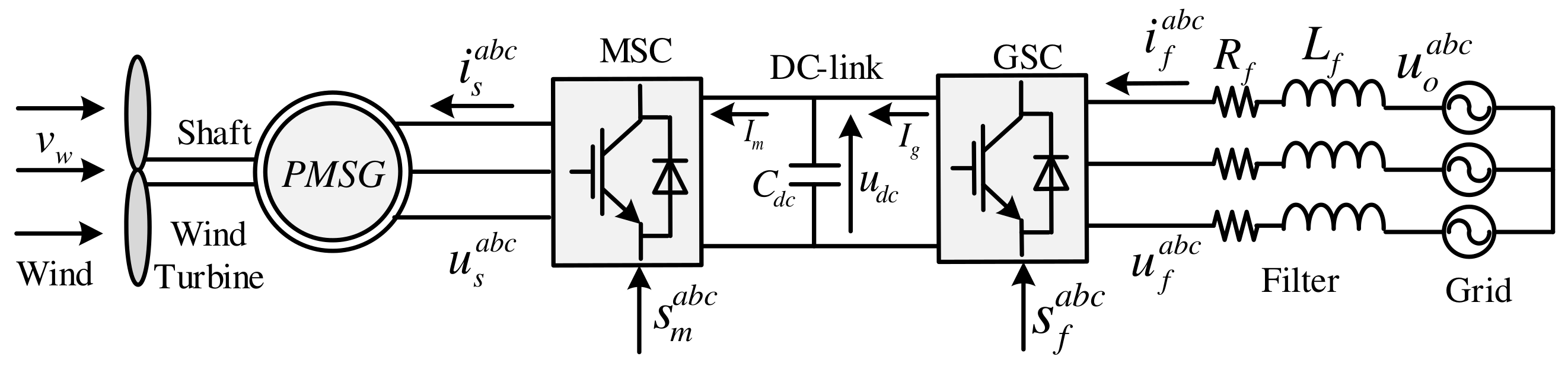
2. Modeling of the Wind Turbine and PMSG

The structure of the variable-speed modern wind energy conversion system with PMSG is illustrated in Figure 1. It can be observed that the wind turbine and the PMSG are directly coupled without the use of a gearbox. Therefore, the output voltage and frequency from the PMSG are not constant. Hence, a full-scale back-to-back power converter (B2B-PC) is essential to tie the system with the grid. The B2B-PC consists of a machine-side converter (MSC), DC-Link, and grid-side converter (GSC). The focus of this work is the control of the MSC. Therefore, only the model of the wind turbine and the PMSG are explained in this work.

2.1. Modeling of the Wind Turbine

The main job of the wind turbine is to convert wind energy to mechanical energy, which can be calculated by the following [29]:
p t = 1 2 c p ρ π r t 2 v w 3 ,
where ρ is the density of the air, r t is wind turbine radius, c p is the power coefficient, and v w is the wind speed.
The power coefficient c p can be expressed as follows [30]:
c p = 0.5176 116 λ i 0.4 β 5 21 λ i + 0.0068 λ 1 λ i : = 1 λ + 0.08 β 0.035 β 3 + 1 .
In (2), β is the pitch angle and λ is the tip speed ration and can be expressed as follows:
λ = ω m r t v w
Normally, the wind turbine operates in four regions based on the speed of the wind [29]; see Figure 2. Those four regions are as follows:
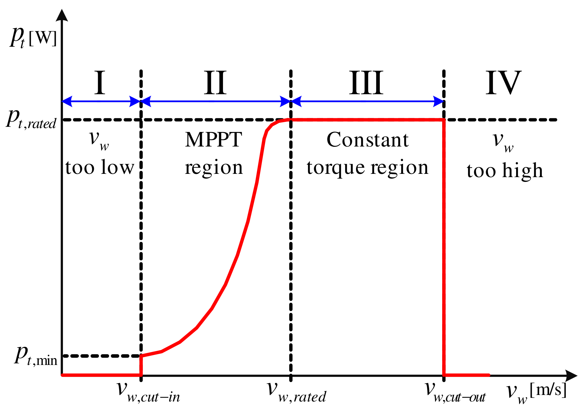
  • Region I: In this region, the speed of the wind is lower than the cut-in value v w < v w , c u t i n of the wind turbine. Accordingly, the wind turbine does not work in this region and the generated power is zero (i.e., p t = 0 ).
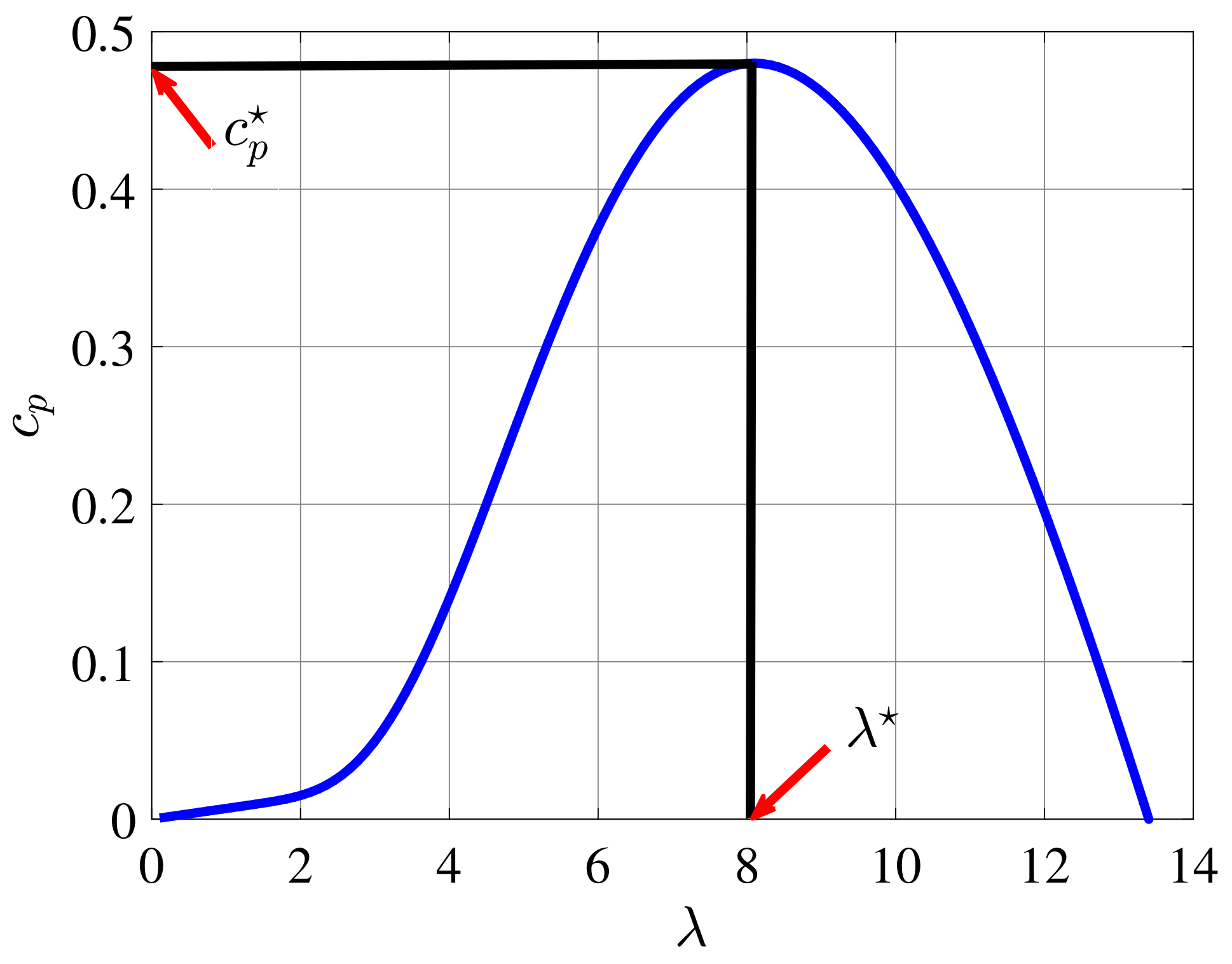
  • Region II: In this zone, the velocity of the wind is higher than the cut-in value v w , c u t i n and lower than the rated wind speed v w , r a t e d , i.e., v w , c u t i n < v w < v w , r a t e d . Subsequently, the wind turbine works in this region. Furthermore, an algorithm is utilized to produce the maximum power from the wind turbine by operating at the optimal tip speed ratio λ . Accordingly, the power coefficient has its maximum value c p and β = 0 , see Figure 3. In this conditions, the generated power can be written as follows:
    p t : = 1 2 c p ρ π r t 2 v w 3 .
    Based on Equation (3), p t can be expressed as follows:
    p t : = 1 2 c p ρ π r t 2 ω m r t λ 3 .
    Subsequently, the optimum mechanical torque is written as follows:
    T m = p t ω m = k p ( ω m ) 2 , k p : = 1 2 ρ π r t 5 c p ( λ ) 3
    The maximum power point tracking (MPPT) is realized by the nonlinear speed controller as follows:
    T e = k p ω m 2 ,
    which force the mechanical angular speed ω m of the rotor to achieve the following condition ω m r t v w = ! λ . This method is called optimal torque control (OTC).
  • Region III: In this zone, the wind speed is higher than the rated value v w , r a t e d and lower than the cut-out wind speed v w , c u t o u t of the wind turbine. Therefore, in this region, the wind turbine generates the rated power p t , r a t e d and torque T e , r a t e d . This is achieved by increasing the pitch angle β .
  • Region IV: In this zone, the velocity of the wind is higher than the cut-out value v w > v w , c u t o u t . Increasing the pitch angle is not effective in limiting the output power. Accordingly, the turbine is shut down and no power is generated (i.e., p t = 0 ).

2.2. Permanent-Magnet Synchronous Generator (PMSG)

Usually, a surface-mounted PMSG is employed in wind generation systems, where the permanent magnets are placed on the rotor surface separated by non-ferrite materials between two adjacent magnets [31]. The permeability of the magnets is almost the same as that of the non-ferrite materials. Accordingly, the effective air gap between the rotor and stator is uniform. Based on this fact, the d- and q-axis inductance are approximately equal (i.e., L s d = L s q = : L s no anisotropy). Therefore, the stator voltage of the PMSG in the a b c reference frame can be written as follows [7]:
u s a = R s i s a + d d t ψ s a , u s b = R s i s b + d d t ψ s b , u s c = R s i s c + d d t ψ s c ,
where
d d t ψ s a = L s d d t i s a + e s a , d d t ψ s b = L s d d t i s b + e s b , d d t ψ s c = L s d d t i s c + e s c .
In the above equations, u s a , u s b , and u s c are the stator voltages of the PMSG. The stator currents are i s a , i s b , and i s c . ψ s a , ψ s b and ψ s c are the stator fluxes of the PMSG. The back electro-motive forces are e s a , e s b , and e s c . R s and L s are the stator resistance and inductance, respectively.
By the help of Clarke transformation [7], the stator voltages of the PMSG are written in the stationary reference frame as follows:
u s α = R s i s α + d d t ψ s α , u s β = R s i s β + d d t ψ s β .
Subsequently, using Park transformation, the stator voltages of the PMSG are written in the rotating reference frame as follows:
u s d = R s i s d + d d t ψ s d ω r ψ s q , u s q = R s i s q + d d t ψ s q + ω r ψ s d .
The PMSG flux in the d q frame can be expressed as follows:
ψ s d = L s i s d + ψ p , ψ s q = L s i s q .
The dynamics of the mechanics of the wind turbine system are given by the following:
d ω m d t = 1 Θ T m T e ,
where
T e ( t ) = 3 2 n p ψ p i s q
is the electro-magnetic machine torque and T m is the mechanical torque. Θ is the rotor inertia and n p is the pole pair number.
Inserting Equation (12) into Equation (11) gives the following:
u s d = R s i s d + L s d d t i s d ω r L s i s q , u s q = R s i s q + L s d d t i s q + ω r L s i s d + ω r ψ p .
In order to design the DB-PC, the discrete-time model is essential. Hence, by using the forward Euler method, the discrete-time model is written as follows:
u s d [ k ] = R s i s d [ k ] + L s i s d [ k + 1 ] i s d [ k ] T s ω r [ k ] L s i s q [ k ] , u s q [ k ] = R s i s q [ k ] + L s i s q [ k + 1 ] i s q [ k ] T s + ω r [ k ] L s i s d [ k ] + ω r [ k ] ψ p .
In (16), T s is the sampling time and the current sample is k.

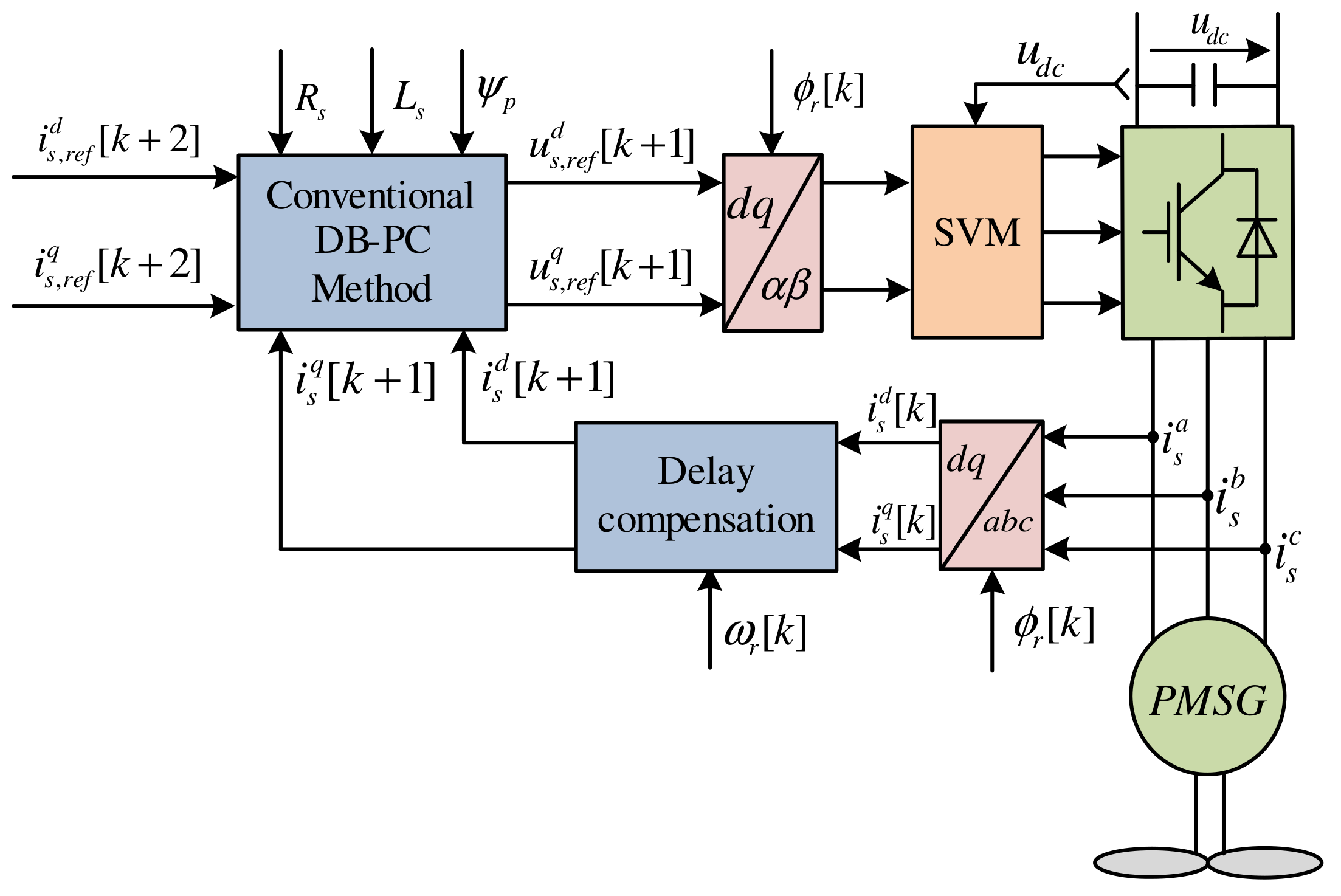
3. Traditional Deadbeat Predictive Control

In the above model of the PMSG, the values of R s , L s , and ψ p are taken from the data-sheet of the machine, or measured in the laboratory. However, due to the change in operation conditions, frequency, temperature, etc., the values of those parameters vary. In the traditional deadbeat predictive control (DB-PC), the effect of variations of the PMSG parameters is neglected. Based on the principles of DB-PC and taking the one sample delay into consideration, the actuation voltage of the next sample is computed as follows [7]:
u s , r e f d [ k + 1 ] = R s i s d [ k + 1 ] + L s i s , r e f d [ k + 2 ] i s d [ k + 1 ] T s ω r [ k + 1 ] L s i s q [ k + 1 ] , u s , r e f q [ k + 1 ] = R s i s q [ k + 1 ] + L s i s , r e f q [ k + 2 ] i s q [ k + 1 ] T s + ω r [ k + 1 ] L s i s d [ k + 1 ] + ω r ψ p .
In (17), the currents i s d [ k + 1 ] and i s q [ k + 1 ] are obtained from (16) as follows:
i s d [ k + 1 ] = ( 1 T s R s L s ) i s d [ k ] + T s ω r [ k ] i s q [ k ] + T s L s u s d [ k ] , i s q [ k + 1 ] = ( 1 T s R s L s ) i s q [ k ] T s ω r [ k ] i s q [ k ] T s ω r [ k ] ψ p + T s L s u s q [ k ] .
It can be observed from Equations (17) and (18) that the calculation of the reference voltage is highly dependent on the parameters of the PMSG. Subsequently, the traditional DB-PC is not a robust controller. The block-diagram of the traditional DB-PC is illustrated in Figure 4.
The reference q-axis current is obtained from the optimum torque T e (see (7)) by using Equation (14), i.e., i s , r e f q [ k ] = 2 3 n p ψ p T e [ k ] . The reference value of the d-axis current is set to zero to achieve the maximum torque per ampere, i.e., i s , r e f q [ k ] = 0 . Subsequently, by the help of Lagrange extrapolation, the reference currents in the sample k + 2 can be computed as follows:
i s , r e f d [ k + 2 ] = 3 i s , r e f d [ k ] 3 i s , r e f d [ k 1 ] + i s , r e f d [ k 2 ] , i s , r e f q [ k + 2 ] = 3 i s , r e f q [ k ] 3 i s , r e f q [ k 1 ] + i s , r e f q [ k 2 ] .

4. Proposed Deadbeat Predictive Control

Based on the fact that the parameters of the PMSG are varying, Equation (16) can be rewritten as follows:
u s d [ k ] = ( R s + Δ R s ) i s d [ k ] + ( L s + Δ L s ) i s d [ k + 1 ] i s d [ k ] T s ω r [ k ] ( L s + Δ L s ) i s q [ k ] + ε s d [ k ] , u s q [ k ] = ( R s + Δ R s ) i s q [ k ] + ( L s + Δ L s ) i s q [ k + 1 ] i s q [ k ] T s + ω r [ k ] ( L s + Δ L s ) i s d [ k ] + ω r [ k ] ( ψ p + Δ ψ p ) + ε s q [ k ] ,
where Δ R s , Δ L s , and Δ ψ p represent the variation in the parameters of the PMSG. ε s d and ε s q represent any un-modeled dynamics or uncertainties. Equation (20) can be written as follows:
u s d [ k ] = R s i s d [ k ] + L s i s d [ k + 1 ] i s d [ k ] T s ω r [ k ] L s i s q [ k ] + ϱ s d , u s q [ k ] = R s i s q [ k ] + L s i s q [ k + 1 ] i s q [ k ] T s + ω r [ k ] L s i s d [ k ] + ω r [ k ] ψ p + ϱ s q ,
where
ϱ s d = Δ R s i s d [ k ] + Δ L s i s d [ k + 1 ] i s d [ k ] T s ω r [ k ] Δ L s i s q [ k ] + ε s d , ϱ s q = Δ R s i s q [ k ] + Δ L s i s q [ k + 1 ] i s q [ k ] T s + ω r [ k ] Δ L s i s d [ k ] + ω r [ k ] Δ ψ p + ε s q ,
The values of ϱ s d and ϱ s q are unknown and must be estimated.
In the proposed DB-PC scheme, the effect of variations of the PMSG parameters is considered in the calculation of the reference voltage for the next sample. Accordingly, the reference voltage is computed as follows:
u s , r e f d [ k + 1 ] = R s i ^ s d [ k + 1 ] + L s i s , r e f d [ k + 2 ] i ^ s d [ k + 1 ] T s ω ^ r [ k + 1 ] L s i ^ s q [ k + 1 ] + ϱ ^ s d , u s , r e f q [ k + 1 ] = R s i ^ s q [ k + 1 ] + L s i s , r e f q [ k + 2 ] i ^ s q [ k + 1 ] T s + ω ^ r [ k + 1 ] L s i ^ s d [ k + 1 ] + ω ^ r ψ p + ϱ ^ s q .
In Equation (23), ϱ ^ s d and ϱ ^ s d are added to the reference voltage calculation to compensate for parameter mismatches of the PMSG. Those values are estimated by the help of an extended Kalman filter (EKF). Furthermore, i ^ s d [ k + 1 ] , i ^ s q [ k + 1 ] , ω ^ r [ k + 1 ] , and ϕ ^ r [ k + 1 ] are also estimated by the same EKF.Accordingly, the proposed DB-PC is robust to mismatches in the parameters of the PMSG. Furthermore, due to the filtering capability of the EKF, the total harmonic distortion (THD) of the stator currents using the proposed DB-PC technique is lower than the THD of the stator currents in the case of using the traditional DB-PC method.
The EKF is implemented with the help of the following state-space model.
d d t x = g ( x , u ) , and y = h ( x ) .
In Equation (24), x is the state vector, y is the output vector, and u is the input vector. These vectors are defined as follows:
x = i s α , i s β , ω r , ϕ r , ϱ s α ϱ s β y = i s α , i s β u = u s α , u s β .
In Equation (24), g ( x , u ) and h ( x ) can be defined as follows:
g ( x , u ) = R s L s i s α + ω r ψ p m L s sin ( ϕ r ) + 1 L s u s α ϱ s α R s L s i s β ω r ψ p m L s cos ( ϕ r ) + 1 L s u s β ϱ s β 0 ω r 0 0
and
h ( x ) = 1 0 0 0 0 0 0 1 0 0 0 0 = : C x .
It is essential to express this model in the discrete-time model as follows:
x [ k + 1 ] = x [ k ] + T s g ( x [ k ] , u [ k ] ) = : f ( x [ k ] , u [ k ] ) + w [ k ] , y [ k ] = h ( x [ k ] ) + v [ k ] .
In Equation (28), the variables w [ k ] and v [ k ] are included to consider the uncertainties in the model of the PMSG and the noise in the measured vector. To simplify the design of the EKF, the covariance matrices are considered to be constants, i.e.,
Q = E { w [ k ] w [ k ] } , R = E { v [ k ] v [ k ] } .
The estimation of the state vector by the EKF is realized by the following:
x ^ [ k + 1 ] = f ( x ^ [ k ] , u [ k ] ) + K [ k ] y [ k ] y ^ [ k ] , y ^ [ k ] = h ( x ^ [ k ] ) = C x ^ [ k ] .
In Equation (30), K is the Kalman gain. The flowchart of the EKF is illustrated in Figure 5 and the block diagram of the proposed DB-PC technique is depicted in Figure 6.
Note: In Equation (26), the variations of the machine parameters and un-modeled dynamics are assume very slow. Therefore, d d t ϱ s α and d d t ϱ s β are zero, which is the accepted assumption [32,33,34]. Furthermore, due to the fact that the mechanical time constant is very long in comparison to the sampling time, it is accepted to assume d d t ω r = 0 [35].

5. Results and Discussion

In order to validate the proposed DB-PC technique, the test bench depicted in Figure 7 is constructed in the laboratory. The list of parameters for the PMSG under test is given in Table 1. In reality, the stator of the PMSG is connected to the grid via a two-level back-to-back power converter as illustrated in Figure 1. However, due to limitations in the hardware components, the schematic diagram of the constructed test bench for PMSG is illustrated in Figure 8. The setup consists of a 14.5   k W PMSG, driven by a two-level power converter (machine-side converter (MSC)), which is connected to the grid via a three-phase diode rectifier. The DC-link contains a chopper circuit to dissipate the generated power from the PMSG. The maximum power that can be dissipated in this chopper circuit is 10   k W . Therefore, the generated power in the following operation conditions is lower than 10   k W .
Due to the fact that there is no wind turbine emulator available in the laboratory, a reluctance synchronous machine (RSM) is used for this purpose. The RSM is driven by another two-level power converter called a wind-turbine emulator side converter (WTE-SC). A dSPACE DS1007 real-time platform with Control Desk and MATLAB/Simulink is utilized for implementing the proposed DB-PC with EKF for the PMSG. For comparison purpose, an incremental encoder with 2048 pulses per revolution (ppr) is used to measure the rotor position of the PMSG, which is fed to dSPACE using a DS3002 incremental encoder board. Three current sensors and one voltage sensor are used to measure the stator currents of the PMSG and the DC-link voltage, respectively. The measured currents and voltage are available in dSPACE via a DS2004 analog-to-digital converter (A/D) board. The power converters are controlled by dSPACE through a DS5101 pulse-width-modulation board.
In real wind turbines, the torque and speed change at the same time. Therefore, the RSM is employed to control the rotor speed, and the PMSG controls the torque, where the reference torque is computed as a function in the speed, i.e., T e [ k ] = 0.0061 ω m 2 [ k ] (i.e., k p = 0.0061 ). k p is selected based on the rated torque of the RSM.
As illustrated in Figure 2, the wind turbine does not work when the wind speed is lower than the cut-in value. Therefore, zero speed and extremely low speeds do not belong to the operation speeds of the PMSG. In this work, the operation speed range of the mechanical speed ω m = ω r / n p is selected from 8   rad / s to 100   rad / s . Furthermore, in the large modern wind turbines in the range of MW, the switching frequency is low to limit the switching losses in the power electronics devices. Therefore, in order to be close to the reality, the switching frequency is selected 4   kHz in this work.
The estimation performance of the suggested EKF at step change in the rotor speed is depicted in Figure 9. The reference mechanical speed for the RSM is stepped from 8   rad / s to 58   rad / s , i.e., the electrical angular speed ω r = n p ω m of the PMSG is changed from 24   rad / s to 174   rad / s . Accordingly, the reference torque of the PMSG T e = 0.0061 ω m 2 is changed from T e = 0.0061 × 8 2 = 0.3904   Nm to T e = 0.0061 × 58 2 = 20.52   Nm at the same time. It can be seen from Figure 9 that the estimation performance of the proposed EKF is very good. The steady-state estimation errors of the stator currents ( i s α , i s β ) and the rotor speed and position ( ω r , ϕ r ) are almost zero at low and high speeds (i.e., 8   rad / s and 58   rad / s ). Furthermore, the dynamic estimation error is very small and converge quickly to zero. Therefore, by the help of the designed EKF, control of the PMSG is possible without using incremental encoders or speed transducers.
Another advantage of the proposed EKF is its ability to filter the harmonics in the measured stator currents. The mechanical speed ω m of the rotor is set to 15   rad / s by the RSM. Accordingly, the reference torque of the PMSG T e = 0.0061 ω m 2 is set to T e = 0.0061 × 15 2 = 1.3725   Nm . The values of the speed and torque are selected to be low to give the worst case of harmonic distortion. In Figure 10, the measured and estimated α -axis stator current of the PMSG is illustrated. According to Figure 10, the EKF shows good ability in filtering the harmonics in the stator currents of the PMSG. The total harmonic distortion (THD) of the measured current is 10.18 % , while the THD of the estimated current by the EKF is 6.32 % . Accordingly, the torque ripples using the proposed DB-PC technique are lower than the ripples in the case of using the traditional DB-PC.
The responses of the suggested DB-PC technique and the traditional one under mismatches in the stator inductance of the PMSG are illustrated in Figure 11. Firstly, for both the proposed DB-PC and classical one, the parameters used in the software models are the measured ones; see the time-range from 3.6   s to 4   s in Figure 11. Although the measured parameters are used in this time-range (i.e., from 3.6   s to 4   s ), one can observe that the actual currents i s d and i s q deviate from their reference values, using the traditional DB-PC. The absolute values of the steady-state errors (AV-SSEs) in the d- and q-axis currents, using the traditional DB-PC, are 1.06   A and 0.12   A , respectively. This experimental results confirm that the measured parameters vary all the time, due to variations of temperature, frequency, etc. In contrast to the traditional DB-PC, the currents i s d and i s q perfectly follow the reference values using the proposed DB-PC, due to the inclusion of ϱ ^ s d and ϱ ^ s q in the calculation of the reference voltage as explained in Section 4. The AV-SSEs in the d- and q-axis currents using the proposed DB-PC are zero. Secondly, at the time instant t = 4   s , the value of the stator inductance of the PMSG is reduced to 60 % of its measured value in the software models of the proposed DB-PC and classical one. Based on Figure 11, the deviations of the currents i s d and i s q from their reference values are increased using the traditional DB-PC method, and the AV-SSEs in the d- and q-axis currents are increased to 1.75   A and 0.16   A , respectively. Furthermore, the ripples in the current waveforms are also increased, particularly in the q-axis current. This is not the case when using the proposed DB-PC technique for which the currents i s d and i s q still track the reference values with very good accuracy, and the AV-SSEs in the d- and q-axis currents are still zero. Additionally, the increase in the ripples is very small in comparison with the traditional DB-PC. In Figure 11, the estimated ϱ ^ s d and ϱ ^ s q by the EKF are also given.
The robustness of the proposed DB-PC and traditional one is also investigated under variation of the permanent-magnet flux linkage ψ p , see Figure 12. The value of the permanent-magnet flux linkage ψ p is increased by 20 % compared to the measured value (i.e., 1.2 ψ p ) in the software model. It is clear that the traditional DB-PC is highly sensitive to variations of the permanent-magnet flux linkage for which a large deviation between the currents i s d and i s q and their reference values is seen. The AV-SSEs in the d- and q-axis currents using the traditional DB-PC are 1.72   A and 2.15   A , respectively. This deviation is zero in the case of using the proposed DB-PC technique, where the currents i s d and i s q follow the reference values with excellent accuracy, i.e., the AV-SSEs in the d- and q-axis currents are still zero.
Finally, the performance of the proposed/traditional DB-PC is tested under change of the rotor speed and torque at the same time, which represents change of the wind speed in reality. In Figure 13, the mechanical rotational speed of the rotor is changed from 16   rad / s to 81   rad / s at the time instant t = 4   s . Accordingly, the reference torque of the PMSG T e = 0.0061 ω m 2 is changed from T e = 0.0061 × 16 2 1.6   Nm to T e = 0.0061 × 81 2 40   Nm . It can be seen that the proposed DB-PC demonstrates better performance than the traditional DB-PC. After changing the speed/torque, the AV-SSEs for the d- and q-axis currents using the proposed DB-PC are zero, while the AV-SSEs for the d- and q-axis currents using the traditional DB-PC are 1.8   A and 0.28   A , respectively.

6. Conclusions

In this paper, a deadbeat predictive control (DB-PC) technique for permanent-magnet synchronous generators (PMSGs) in variable-speed wind turbines is proposed. To enhance the robustness of the suggested DB-PC scheme, an extended Kalman filter (EKF) was designed to estimate the total disturbance caused by variations of the PMSG parameters. Then, this total disturbance was included in design of the DB-PC strategy. Furthermore, the designed EKF estimates the rotor speed and position of the PMSG, i.e., no incremental encoders are required and the reliability of the drive system is improved. The suggested DB-PC technique and the traditional one were implemented in the laboratory. The experimental results proved that the proposed DB-PC technique with EKF is robust to mismatches in the PMSG parameters, while the traditional DB-PC is highly sensitive. Furthermore, the estimation of the rotor speed and position by the EKF is accurate. Finally, the EKF is able to filter the stator current waveforms of the PMSG and reduce the total harmonic distortion in comparison with the traditional DB-PC.

Author Contributions

The design and implementation of the proposed control technique was achieved by M.A. The writing of the whole manuscript and drawing of the figures were also realized by M.A. The test-bench used to implement the proposed control strategy was provided by C.H. The review of the manuscript was achieved by C.H. and R.K. The guidance and suggestions during this work were provided by R.K. All authors have read and agreed to the published version of the manuscript.

Funding

This research received no external funding.

Institutional Review Board Statement

Not applicable.

Informed Consent Statement

Not applicable.

Data Availability Statement

Not applicable.

Conflicts of Interest

The authors declare no conflict of interest.

References

  1. Bimal, K. Bose, Power Electronics in Renewable Energy Systems and Smart Grid: Technology and Applications; Wiley-IEEE Press: Hoboken, NJ, USA, 2019. [Google Scholar]
  2. Shourangiz-Haghighi, A.; Diazd, M.; Zhang, Y.; Li, J.; Yuan, Y.; Faraji, R.; Ding, L.; Guerrero, J.M. Developing More Efficient Wind Turbines: A Survey of Control Challenges and Opportunities. IEEE Ind. Electron. Mag. 2020, 14, 53–64. [Google Scholar] [CrossRef]
  3. Ahmed, S.D.; Al-Ismail, F.S.M.; Shafiullah, M.; Al-Sulaiman, F.A.; El-Amin, I.M. Grid Integration Challenges of Wind Energy: A Review. IEEE Access 2020, 8, 10857–10878. [Google Scholar] [CrossRef]
  4. Tang, X.; Hu, Y.; Chen, Z.; You, G. Flexibility Evaluation Method of Power Systems with High Proportion Renewable Energy Based on Typical Operation Scenarios. Electronics 2020, 9, 627. [Google Scholar] [CrossRef]
  5. Orlando, N.A.; Liserre, M.; Mastromauro, R.A.; Dell’Aquila, A. A Survey of Control Issues in PMSG-Based Small Wind-Turbine Systems. IEEE Trans. Ind. Inform. 2013, 9, 1211–1221. [Google Scholar] [CrossRef]
  6. Mahmoud, M.S.; Oyedeji, M.O. Adaptive and predictive control strategies for wind turbine systems: A survey. IEEE/CAA J. Autom. Sin. 2019, 6, 364–378. [Google Scholar] [CrossRef]
  7. Abdelrahem, M. Predictive Control and Finite-Set Observers for Variable-Speed Wind Generators. Ph.D. Thesis, Technische Universität München, Munich, Germany, 2020. Available online: https://mediatum.ub.tum.de/1520001 (accessed on 10 May 2021).
  8. Abdelrahem, M.; Hackl, C.M.; Kennel, R. Limited-Position Set Model-Reference Adaptive Observer for Control of DFIGs without Mechanical Sensors. Machines 2020, 8, 72. [Google Scholar] [CrossRef]
  9. Abdelrahem, M.; Hackl, C.M.; Rodríguez, J.; Kennel, R. Model Reference Adaptive System with Finite-Set for Encoderless Control of PMSGs in Micro-Grid Systems. Energies 2020, 13, 4844. [Google Scholar] [CrossRef]
  10. Chinchilla, M.; Arnaltes, S.; Burgos, J. Control of permanent-magnet generators applied to variable-speed wind-energy systems connected to the grid. IEEE Trans. Energy Convers. 2006, 21, 130–135. [Google Scholar] [CrossRef] [Green Version]
  11. Vafaie, M.H. Performance Improvement of Permanent-Magnet Synchronous Motor Through a New Online Predictive Controller. IIEEE Trans. Energy Convers. 2019, 34, 2258–2266. [Google Scholar] [CrossRef]
  12. Hammoud, I.; Xu, K.; Hentzelt, S.; Oehlschlaegel, T.; Kennel, R. On Offset-Free Continuous Model Predictive Current Control of Permanent Magnet Synchronous Motors. IFAC-PapersOnLine 2020, 53, 6662–6669. [Google Scholar] [CrossRef]
  13. Vazquez, S.; Rodriguez, J.; Rivera, M.; Franquelo, L.G.; Norambuena, M. Model Predictive Control for Power Converters and Drives: Advances and Trends. IEEE Trans. Ind. Electron. 2017, 64, 935–947. [Google Scholar] [CrossRef] [Green Version]
  14. Valencia, D.F.; Tarvirdilu-Asl, R.; Garcia, C.; Rodriguez, J.; Emadi, A. Vision, Challenges, and Future Trends of Model Predictive Control in Switched Reluctance Motor Drives. IEEE Access 2021, 9, 69926–69937. [Google Scholar] [CrossRef]
  15. Morel, F.; Lin-shi, X.F.; Retif, J.M. A comparative study of predictive current control schemes for a permanent magnet synchronous machine drive. IEEE Trans. Ind. Electron. 2009, 56, 2715–2728. [Google Scholar] [CrossRef] [Green Version]
  16. Alexandrou, A.D.; Adamopoulos, N.K.; Kladas, A.G. Development of a Constant Switching Frequency Deadbeat Predictive Control Technique for Field-Oriented Synchronous Permanent-Magnet Motor Drive. IEEE Trans. Ind. Electron. 2016, 63, 5167–5175. [Google Scholar] [CrossRef]
  17. Abdelrahem, M.; Hackl, C.; Kennel, R. Simplified Model Predictive Current Control without Mechanical Sensors for Variable-Speed Wind Energy Conversion Systems. Electr. Eng. J. 2017, 99, 367–377. [Google Scholar] [CrossRef]
  18. Mehreganfar, M.; Saeedinia, M.H.; Davari, S.A.; Garcia, C.; Rodriguez, J. Sensorless Predictive Control of AFE Rectifier With Robust Adaptive Inductance Estimation. IEEE Trans. Ind. Inform. 2019, 15, 3420–3431. [Google Scholar] [CrossRef]
  19. Cheng, L.-J.; Tsai, M.-C. Enhanced Model Predictive Direct Torque Control Applied to IPM Motor with Online Parameter Adaptation. IEEE Access 2020, 8, 42185–42199. [Google Scholar] [CrossRef]
  20. Yao, Y.; Huang, Y.; Peng, F.; Dong, J.; Zhang, H. An Improved Deadbeat Predictive Current Control with Online Parameter Identification for Surface-Mounted PMSMs. IEEE Trans. Ind. Electron. 2019, 67, 10145–10155. [Google Scholar] [CrossRef] [Green Version]
  21. Hammoud, I.; Morsy, K.; Abdelrahem, M.; Kennel, R. Efficient model predictive power control with online inductance estimation for photovoltaic inverters. Electr. Eng. 2020, 102, 549–562. [Google Scholar] [CrossRef]
  22. Abdelrahem, M.; Hackl, C.; Zhang, Z.; Kennel, R. Robust Predictive Control for Direct-Driven Surface-Mounted Permanent-Magnet Synchronous Generators Without Mechanical Sensors. IEEE Trans. Energy Convers. 2018, 33, 179–189. [Google Scholar] [CrossRef]
  23. Zhang, X.; Hou, B.; Mei, Y. Deadbeat Predictive Current Control of Permanent-Magnet Synchronous Motors with Stator Current and Disturbance Observer. IEEE Trans. Power Electron. 2017, 32, 3818–3834. [Google Scholar] [CrossRef]
  24. Tang, P.; Dai, Y.; Li, Z. Unified Predictive Current Control of PMSMs with Parameter Uncertainty. Electronics 2019, 8, 1534. [Google Scholar] [CrossRef] [Green Version]
  25. Abdelrahem, M.; Hackl, C.M.; Kennel, R.; Rodriguez, J. Efficient Direct Model Predictive Control with Discrete Time Integral Action for PMSGs. IEEE Trans. Energy Convers. 2019, 34, 1063–1072. [Google Scholar] [CrossRef]
  26. Zhu, Y.; Tao, B.; Xiao, M.; Yang, G.; Zhang, X.; Lu, K. Luenberger Position Observer Based on Deadbeat-Current Predictive Control for Sensorless PMSM. Electronics 2020, 9, 1325. [Google Scholar] [CrossRef]
  27. Abdelrahem, M.; Hackl, C.; Kennel, R. Finite Position Set-Phase Locked Loop for Sensorless Control of Direct-Driven Permanent-Magnet Synchronous Generators. IEEE Trans. Power Electron. 2018, 33, 3097–3105. [Google Scholar] [CrossRef]
  28. Wang, G.; Valla, M.I.; Solsona, J.A. Position Sensorless Permanent Magnet Synchronous Machine Drives—A Review. IEEE Trans. Ind. Electron. 2020, 67, 5830–5842. [Google Scholar] [CrossRef]
  29. Wu, B.; Lang, Y.; Zargari, N.; Kouro, S. Power Conversion and Control of Wind Energy Systems; Wiley-IEEE Press: Hoboken, NJ, USA, 2011. [Google Scholar]
  30. Heier, S. Grid Integration of Wind Energy Conversion Systems; John Wiley & Sons Ltd.: Hoboken, NJ, USA, 1998. [Google Scholar]
  31. Boldea, I. Variable Speed Generators; Taylor and Francis Group, LLC: Abingdon, UK, 2006. [Google Scholar]
  32. Li, X.; Kennel, R. General Formulation of Kalman-Filter-Based Online Parameter Identification Methods for VSI-Fed PMSM. IEEE Trans. Ind. Electron. 2021, 68, 2856–2864. [Google Scholar] [CrossRef]
  33. Boileau, T.; Leboeuf, N.; Nahid-Mobarakeh, B.; Meibody-Tabar, F. Online Identification of PMSM Parameters: Parameter Identifiability and Estimator Comparative Study. IEEE Trans. Ind. Appl. 2011, 47, 1944–1957. [Google Scholar] [CrossRef]
  34. Nalakath, S.; Preindl, M.; Emadi, A. Online multi-parameter estimation of interior permanent magnet motor drives with finite control set model predictive control. IET Electr. Power Appl. 2017, 11, 944–951. [Google Scholar] [CrossRef] [Green Version]
  35. Bolognani, S.; Tubiana, L.; Zigliotto, M. Extended Kalman filter tuning in sensorless PMSM drives. IEEE Trans. Ind. Appl. 2003, 39, 1741–1747. [Google Scholar] [CrossRef]
Figure 1. Structure of modern wind turbines with permanent-magnet synchronous generator.
Electronics 10 01596 g001
Figure 2. Regions of operation for modern variable-speed wind turbines.
Electronics 10 01596 g002
Figure 3. Curve of the power coefficient c p at β = 0 .
Electronics 10 01596 g003
Figure 4. Traditional deadbeat predictive control technique for PMSGs.
Electronics 10 01596 g004
Figure 5. Flow chart of the extended Kalman filter.
Electronics 10 01596 g005
Figure 6. Proposed deadbeat predictive control technique for PMSGs.
Electronics 10 01596 g006
Figure 7. Test bench utilized to validate the proposed DB-PC strategy.
Electronics 10 01596 g007
Figure 8. Schematic diagram of the laboratory setup for the PMSG.
Electronics 10 01596 g008
Figure 9. Estimation performance of the proposed EKF at change of the rotor speed: (a) Measured and estimated α -axis current, (b) measured and estimated β -axis current, (c) measured and estimated electrical angular speed of the rotor, and (d) measured and estimated electrical position of the rotor.
Electronics 10 01596 g009
Figure 10. α -axis stator current of the PMSG: (a) measured, and (b) estimated.
Electronics 10 01596 g010
Figure 11. Experimental results of the proposed DB-PC and traditional one at mismatches in the stator inductance L s of the PMSG: (a) actual and reference d-axis currents, (b) actual and reference q-axis currents, (c) observed and reference d-axis currents, (d) observed and reference q-axis currents, and (e) observed total disturbance for d and q axes.
Electronics 10 01596 g011
Figure 12. Experimental results of the proposed DB-PC and traditional one at mismatches in the permanent-magnet flux linkage ψ p : (a) actual and reference d-axis currents, (b) actual and reference q-axis currents, (c) observed and reference d-axis currents, (d) observed and reference q-axis currents, and (e) observed total disturbance for d and q axes.
Electronics 10 01596 g012
Figure 13. Experimental results of the proposed DB-PC and traditional one with change of the torque and speed at the same time: (a) actual and reference d-axis currents, (b) actual and reference q-axis currents, (c) observed and reference d-axis currents, (d) observed and reference q-axis currents, and (e) observed total disturbance for d and q axes.
Electronics 10 01596 g013
Table 1. Parameters of the PMSG under test.
NameSymbolValue
Nominal power p n 14.5   kW
Nominal stator line–line voltage u s , n 400   V
DC-link voltage u d c 560   V
Nominal mechanical angular speed ω m , n 209   rad / s
Stator resistance R s 0.15   Ω
Stator inductance L s 3.4   mH
Permanent-magnet flux linkage ψ p 0.3753   Wb
Pole pairs n p 3
Publisher’s Note: MDPI stays neutral with regard to jurisdictional claims in published maps and institutional affiliations.

