Article

Compact Wideband Coplanar Stripline-to-Microstrip Line Transition Using a Bended Structure on a Two-Layered Substrate

1
School of Electronic and Electrical Engineering, Kyungpook National University, Daegu 41566, Korea
2
Research Institute for Microwave and Millimeter-Wave Studies, National University of Sciences and Technology, Islamabad 44000, Pakistan
3
Department of Electronics and Communication Engineering, SRM Institute of Science and Technology, Chennai 603203, India
*
Author to whom correspondence should be addressed.
Electronics 2021, 10(11), 1272; https://doi.org/10.3390/electronics10111272
Submission received: 6 May 2021 / Revised: 24 May 2021 / Accepted: 25 May 2021 / Published: 26 May 2021
(This article belongs to the Special Issue Ultra-Wideband Microwave/MM-Wave Components and Packaging)

Abstract

:
A design of a compact coplanar strip (CPS)-to-microstrip line (MSL) transition using a bended structure on a two-layered substrate is presented. The proposed transition consists of a CPS taper and a bended CPS-to-MSL transition on a two-layered substrate. The CPS taper is formed on the lower substrate with low permittivity (εr = 3.38), and the bended CPS-to-MSL transition is formed on the upper substrate with high permittivity (εr = 10.2). The proposed transition is designed with analytical formulas obtained by applying EM-based conformal mapping without parametric tuning trials. The conductor shape of the bended CPS-to-MSL transition is adjusted to form an optimal Klopfenstein impedance taper. The proposed CPS-to-MSL transition optimally connects between a high impedance CPS line (~160 Ω) and a 50 Ω MSL, which typically results in a long transition length for ultra-wideband performance. The implemented transition bended in a sinusoid shape on the two-layered substrate provides good performance from 2 GHz to 17 GHz with the maximum 2 dB insertion loss per transition, and the horizontal length of the bended transition is reduced to 42.9% of the straight transition length. This bended transition is developed for use in mm-wave balanced antenna/detector feeds but can be applied to a variety of wideband balanced circuit modules, where compact circuit size is critical.

1. Introduction

A coplanar strip (CPS) line consisting of uniplanar parallel lines is a balanced transmission line. The typical characteristic line impedance range of the CPS line is higher (especially higher with low permittivity substrates, e.g., 100–180 Ω with relative permittivity of 3.38 and thickness of 12 mil (0.31 mm)) than other transmission lines under same manufacturing conditions. The CPS line is often used to feed a balanced planar antenna due to the high radiation efficiency, and its uniplanar and balanced structure, while most of commercial circuits are implemented with a microstrip line (MSL), which is a commonly used unbalanced transmission line. Hence, in designing a microwave component using the CPS line, a transition structure between the CPS line and other transmission lines with proper impedance tapering is required. High-performing CPS-to-MSL transitions with wide-bandwidth and low-insertion loss are often used in microwave/millimeter-wave communication systems [1,2,3,4,5].
Various wideband transitions from a CPS line to other planar transmission lines were reported. In [6], the line impedance of the CPW-to-CPS transition, operating from DC to 165 GHz, was maintained at 50 Ω along the transition in the presence of a ground conductor plane. Also, in this transition, the CPS line was an asymmetric conductor-backed CPS, which was not a conventional CPS line. In [7], a CPW-to-CPS transition, operating from DC to 110 GHz, was designed to connect between a 50 Ω CPW and a 64 Ω CPS on a high-permittivity substrate (dielectric constant of 12.9). With a high-permittivity substrate, a relatively low line impedance of CPS line could be obtained, while the CPS line impedances are much higher with a low-permittivity substrate.
In [8], a CPS-to-MSL transition between a CPS line (161 Ω) and an MSL (50 Ω) was designed with a radial stub and a modified ground plane. The reported transition had an operating bandwidth from 1.3 GHz to 13.3 GHz with 1.5 dB insertion loss per transition and 10 dB return loss. In [9], a CPS-to-MSL transition with a linear stub was reported. The transition operated from 1.3 to 3.2 GHz with 1.5 dB insertion loss per transition and 10 dB return loss. In [10], a CPS-to-MSL transition was designed with a modified ground plane and a vertical signal line using a via. The characteristic impedance of the CPS line was 125 Ω, and the transition had operating bandwidth from 2.3 GHz to 15.4 GHz with 1.3 dB insertion loss per transition and 10 dB return loss. In [11], a CPS-to-MSL transition was developed with a radial stub and a modified ground plane. The transition operated from 5.1 GHz to 6.1 GHz with 1.2 dB insertion loss per transition and 10 dB return loss. Also, a CPS-to-MSL transition was designed with a radial stub and an MSL taper [12]. The characteristic impedance of the CPS line was 124 Ω, and the transition operated from 4.7 GHz to 10.2 GHz with 1.5 dB insertion loss per transition and 10 dB return loss. In [13], a CPS-to-MSL transition with a modified ground plane was reported. The transition operated from 6.9 GHz to 12.4 GHz with 1 dB insertion loss per transition and 10 dB return loss. However, these previous transitions showed limited bandwidth due to lack of the optimal impedance matching. On the other hand, a CPS-to-MSL transition with wideband performance was reported by the author’s group in [14,15], using analytical transition models based on the EM-based conformal mapping technique.
Since the CPS line impedance with a typical fabrication process is high as compared with that of an MSL, a CPS-to-MSL transition should also provide impedance matching, typically by impedance tapering. For an ideal impedance taper, the highest operating frequency is at infinity. In a practical design, however, the highest frequency will be limited due to the material characteristics. Also, the lowest operating frequency corresponding to the 10 dB return loss is determined by the transition length. Therefore, the start frequency of the transition can be lowered by increasing the transition length. If the CPS line impedance is very high, the overall transition length tends to be very long (~0.4 λ at the start frequency) to have a low start frequency, which can be a problem for use in the compact circuit modules. The reflection characteristics of an impedance taper are well documented in the literature [16]. The horizontal length of the transition can be reduced by adopting a bended structure and/or a high dielectric constant substrate, while maintaining the same electrical length of the transition.
Our study aims to significantly reduce the horizontal length of the CPS-to-MSL transition, which is used to feed a W-band antenna and detector for the electron cyclotron emission (ECE) imaging system of the KSTAR (Korea Superconducting Tokamak Advanced Research) in Korea as shown in Figure 1a. The CPS line impedance to feed the W-band dual-dipole antenna is 158 Ω, and a diode mixer down-converts the W-band signals to produce an IF signal with frequency range from 2 GHz to 9 GHz, which is channeled to the wideband CPS-to-MSL transition as shown in Figure 1b. In [17], a long CPS-to-MSL transition, for the ECE imaging system, was reported without the analytical model. In order to reduce the horizontal length of the transition, a bended CPS-to-MSL transition was developed with wideband performance by the author’s group [18]. With the bended structure, the horizontal length of the transition with impedance tapering can be reduced, causing increase of the occupying structure width, while the width increase can be adjusted for a specific circuit board. The transition size can be further reduced by adopting a high permittivity substrate. On the other hand, for most antenna applications, a low dielectric constant substrate is preferred for good radiation performance.
In this paper, a new design of the compact CPS-to-MSL transition with ultra-wide bandwidth from 2 GHz to 17 GHz using a bended structure on a two-layered substrate is proposed. The Schwarz–Christoffel transformation of the conformal mapping is applied for the planar transition cross-section to obtain the line impedance of each section of the proposed transition in an analytical formula. In order to reduce the horizontal length of the transition, the proposed CPS-to-MSL transition is implemented in a two-layered structure: on the lower substrate, a CPS feed and a CPS impedance taper are formed using the low dielectric constant substrate for the radiation efficiency of the antenna, and on the upper substrate, a bended structure of a sinusoid shape is formed on a high dielectric constant substrate.

2. Design of the Proposed Compact CPS-to-MSL Transition

The proposed compact CPS-to-MSL transition using a bended structure on a two-layered substrate is illustrated in Figure 2. The transition uses two different substrates, and it mainly consists of two parts: a CPS taper and a via connection with length l1, and a bended CPS-to-MSL transition on a two-layered substrate with length l2 as shown in Figure 2a. As shown in Figure 2b, the Duroid 6010 substrate (relative dielectric constant = 10.2) with 10 mil (0.25 mm) thickness is used for the upper substrate, and the Duroid Rogers 4003 (relative dielectric constant = 3.38) substrate with 12 mil (0.31 mm) thickness is used for the lower substrate. The CPS taper is formed on the lower substrate with low dielectric constant, and the bended CPS-to-MSL transition is formed on the upper substrate with high dielectric constant, where the bended transition design helps to reduce the horizontal length of the transition.
Figure 2c illustrates the CPS taper with vias (AA′ to CC′) formed on the lower substrate. From AA′ to BB′, the linewidth w1 of the CPS lines is increased with a fixed gap g1 to reduce the CPS impedance from 158 Ω to 129 Ω [16]. For wideband performance, the CPS taper is formed as a Klopfenstein taper. From BB′ to CC′, the CPS line on the lower substrate is connected with two vias to the upper CPS line with the linewidth of w2 and gap of g2, formed on the top side of the upper substrate. Figure 2d shows the bended CPS-to-MSL transition (CC′ to GG′), formed on the top and bottom conductor layers of the upper substrate. From CC′ to DD′, a short CPS line with the line impedance of 99 Ω is formed. From DD′ to GG′, the CPS-to-MSL transition bended as a sinusoid-shaped structure with the arc radius r is shown. The top-side CPS ground line is connected to the bottom ground line with an array of vias. The linewidth w2 of the signal line is reduced to the linewidth w3 of the MSL (at GG′), reducing the line impedance from 99 Ω to 50 Ω, while the ground plane of the bottom conductor layer is smoothly increased from DD′ to GG′. The section from GG′ to HH′ is a typical MSL. The design parameters of the proposed compact CPS-to-MSL transition are listed in Table 1.

2.1. Electric Field Distribution

The electric field distributions at several cross-sections along the transition are shown in Figure 3. The electric field (dotted red line) lines are shaped depending on the linewidths of the signal line and the ground plane. The lower substrate (blue color) is a low dielectric constant substrate, and the upper substrate (apricot color) is a high dielectric constant substrate.
For a cross-sectional area from AA′ to BB, the electric field distribution of the conventional CPS mode is formed. From BB′ to CC′, two vias are used to connect the top and bottom CPS conductors, and the electric field distribution can be decomposed into a half-plane of the CPS mode in the air for the top conductors, a parallel plate mode between two vias, and a half-plane of the CPS mode for the bottom conductors. The section from CC′ to DD′ is a short CPS line on the top side of the upper substrate, and the electric field distribution of the conventional CPS mode is formed. The section from DD′ to GG′ is the bended CPS-to-MSL transition, and the electric field lines from the top-side signal conductor to the bottom ground line are formed. The bottom ground line is connected to the top-side ground line through an array of vias, and the width of the ground line is increased from DD′ to GG′. The electric field distribution in this section consists of a half-plane of the CPS mode in the air for the top conductors, a CPS mode with the finite bottom ground line inside the upper substrate, and a fringing field mode distributed through two substrates. However, as the linewidth of the ground plane of the bottom conductor becomes larger, the electric field lines under the top-side conductor are mostly distributed inside the upper substrate. Also, as shown in the cross-sectional area of GG′, another fringing field appears at the side region of the signal line. Lastly, from GG′ to HH′, the electric field of the conventional MSL is shown.

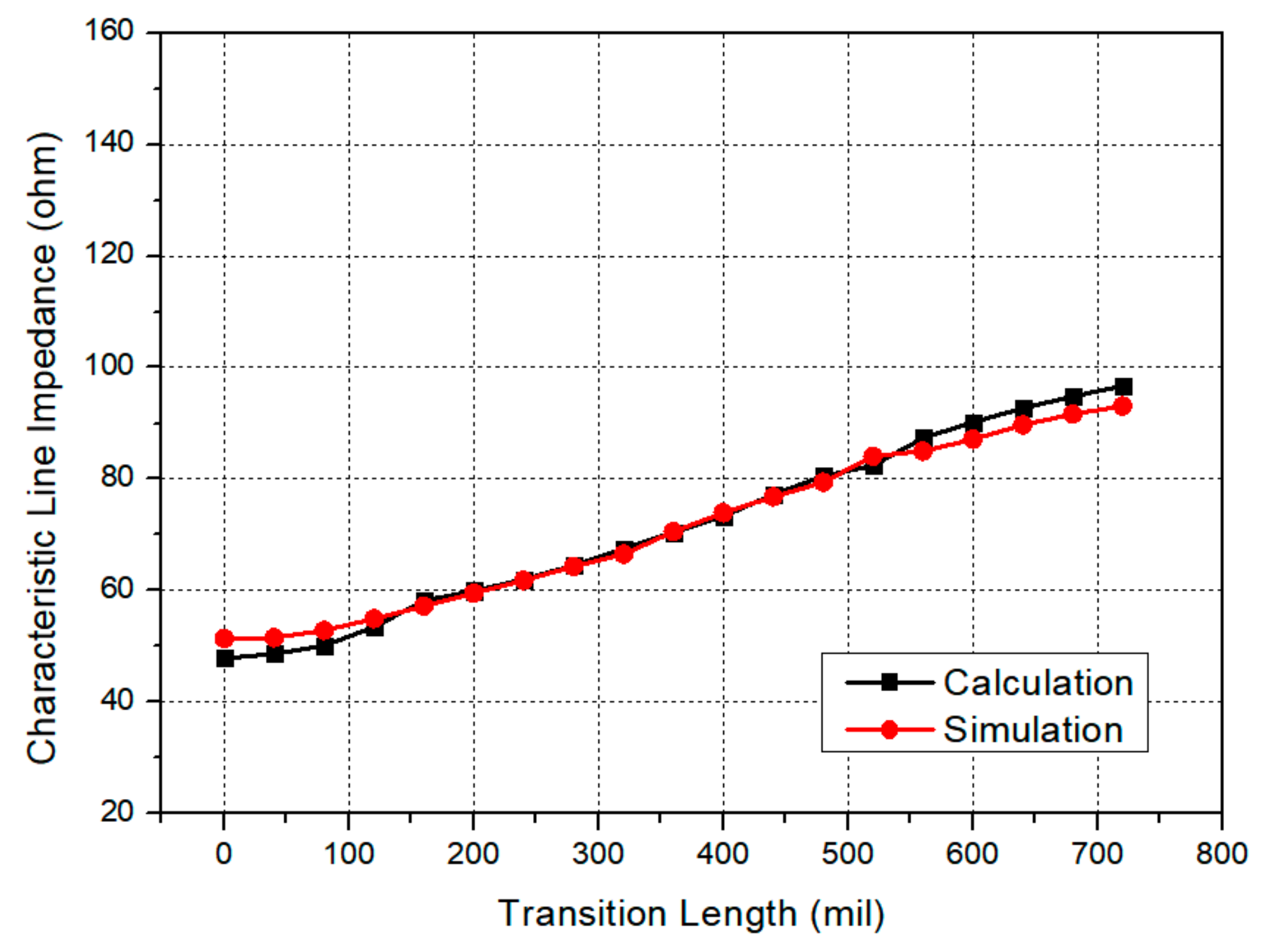
2.2. CPS Taper (AA′ to CC′)

The CPS line is formed on the low permittivity substrate ( ε r = 3.38) from AA′ to BB′ for the antenna efficiency. At AA′, in order to feed the W-band dual-dipole antenna/detector [18], and the CPS line impedance of 158 Ω is required, resulting in a very narrow signal linewidth (w1 = 6 mil (0.15 mm)). The line impedance of the CPS line is optimally tapered from 158 Ω (at AA′) to 129 Ω (at BB′) by increasing the linewidth in a form of a Klopfenstein taper. The CPS line impedances along the transition cross-sectional areas are calculated with an analytical formula obtained with the conformal mapping [19]. In order to compare the calculated and simulated values, 3D EM simulations are performed using the CST Microwave Studio. In Figure 4, the calculated and simulated line impedances are shown with the maximum/average deviation of 3.8% and 2.1%, respectively. The calculated and simulated results show good agreement through the entire sections of the transition.
From BB′ to CC′, the lower CPS line is connected to the upper CPS line using two vias. When the gap widths of the two CPS lines are kept same, the line impedance of the upper CPS line is much lower than that of the lower CPS line due to the higher dielectric constant of the upper substrate. Hence, the gap width of the upper CPS line should be increased to match the line impedance between the two CPS lines. However, if the gap width of the upper CPS line is significantly increased, the two CPS lines cannot be connected by straight vias. In this transition design, the gap of the upper CPS line is increased by 10 mil (0.25 mm), resulting in the line impedance of 99 Ω. Therefore, assuming that an effect of the short vias is negligible, there exists an impedance mismatch between the lower CPS line (129 Ω) and upper CPS line (99 Ω). However, since most impedance changes (AA′ to BB′ and CC′ to GG′) are made with the optimal Klopfenstein tapers, the overall return loss of the transition is slightly degraded due to the impedance mismatch (BB′ to CC′).

2.3. Bended CPS-to-MSL Transition on a Two-Layered Substrate (DD′ to GG′)

Analytical Formulation: A CPS-to-MSL transition (from DD′ to GG′) provides the optimal impedance tapering from 99 Ω (CPS) to 50 Ω (MSL). In order to efficiently design the transition, the characteristic line impedance of a transitional cross-section is obtained using the EM-based analytical formula. Figure 5 shows the cross-sectional model with four analysis regions. In [20], which presented a systematic analysis technique for TEM/quasi-TEM planar transitions by the authors′ group, a similar cross-sectional model (Model II in [20]) was analyzed using the conformal mapping. In the analysis, each region is transformed into parallel conductor plates through the Schwarz–Christoffel transformation.
Region I, where the field lines are distributed in the air, is the upper half-plane of the CPS, resulting in the line capacitance C1 expressed in Equation (1):
C 1 = ε 0 K ( k 1 ) K ( k 1 )
where K is the elliptical integral of the first kind with modulus k 1 and complementary modulus k 1 of Type 2 in [20]. Region II is the inner region of the CPS line with a finite bottom ground plate of the upper substrate with relative dielectric constant ε r . The line capacitance C2 is obtained as:
C 2 = ε r ε 0 K ( k 2 ) K ( k 2 )
where k 2 and k 2 are the modulus and complementary modulus of Type 3 in [20], respectively. Region III is considered as a region with the fringing field distributed in the lower substrate with relative dielectric constant ε r . The line capacitance C3 is obtained as:
C 3 = ε r ε 0 K ( k 3 ) K ( k 3 )
where k 3 and k 3 are the modulus and complementary modulus of Type 5 in [20], respectively. Also, as increasing the bottom ground plane, another fringing field distribution in Region IV results in capacitance C4 expressed by Equation (4):
C 4 = ε r ε 0 K ( k 4 ) K ( k 4 )
where k 4 and k 4 are the modulus and complementary modulus of Type 7 in [20], respectively.
Therefore, by summing up the line capacitances of the analysis regions, the characteristic line impedance and effective dielectric constant of the cross-sectional area of the bended transition are obtained as Equations (5) and (6), respectively.
Z 0 = 120 π ε 0 ε e f f   ( C 1 + C 2 / ε r + C 3 / ε r + C 4 / ε r )
  ε e f f = C 1 + C 2 + C 3 + C 4 C 1 + C 2 / ε r + C 3 / ε r + C 4 / ε r
In Figure 6, the calculated and EM-simulated characteristic line impedances of a two-layered CPS-to-MSL transition are shown with the maximum/average deviation of 5.6% and 2.4%, respectively. Since the proposed CPS-to-MSL transition also acts as an impedance taper, the start frequency can be lowered by increasing the electrical length of the transition. A high permittivity substrate helps to reduce the transition length in realizing the same electrical length as compared with a low permittivity substrate.
Transition as an Impedance Taper: The proposed transition is formed as a Klopfenstein impedance taper, which is an optimal (Chebyshev-type) impedance taper, and the reflection coefficient Γ of the impedance taper is expressed as:
Γ θ = Γ 0 e j θ / 2 cos ( θ / 2 2 cos h 1 Γ 0 / Γ m 2 Γ 0 / Γ m ,     θ = 2 β L
where Γm, β, Γ0 and L are the maximum ripple in the passband, the wave number, the reflection coefficient at zero frequency, and the physical length, respectively [16]. For example, the magnitude of the reflection coefficients of the MSL taper over the frequency with several physical lengths (L) are shown in Figure 7. It can be observed that the reflection magnitude is reduced as the frequency increases. Also, the start frequency corresponding to the 10 dB return loss (|Γ| = 0.316) is lowered as the physical length L is increased: e.g., 2.0 GHz with L = 37 mm (1457 mil), 3.6 GHz with L = 20 mm (787 mil), and 7.3 GHz with L = 10 mm (394 mil). Therefore, to attain the start frequency of 2 GHz, the transition length of 0.39 λ is required: i.e., the ratio between the physical length of 37 mm (1457 mil) and the guided wavelength of the MSL of 96 mm (3780 mil) at 2 GHz on the Rogers 4003 substrate (dielectric constant of 3.38, thickness of 0.31 mm (12 mil)).
Bended Transition: The minimum operating frequency of the proposed CPS-to-MSL transition can be lowered by increasing the physical length of the transition. To attain a very low start frequency of the transition, the overall transition length tends to be very long, which can be a problem for compact circuit modules. For example, in order to achieve the lowest operating frequency at 2 GHz, the straight length of an impedance taper connecting between 158 Ω and 50 Ω lines with 10 dB return loss calculates as 0.39 λ by using Equation (7). With the Rogers 4003 substrate with 12 mil (0.31 mm) thickness, the length of the transition without bending becomes 1928 mil (49 mm), which is too long to be accommodated by a compact circuit module. On the other hand, the horizontal length of the transition can be reduced if the same length transition is configured as a bended structure. Of course, by bending the transition structure, the occupying structure width is increased, and the performance of the transition can be degraded, especially at higher operating frequencies.
In this proposed bended CPS-to-MSL transition, a smooth sinusoid-shaped structure is suggested. If the curvature radius of the bended structure is too small, reflections will degrade the performance. Also, if the bended signal lines are closely spaced, spurious EM couplings will degrade the transition performance [18]. The shapes of the top-side signal and ground conductors as well as the bottom-side ground conductor are carefully designed to achieve the best performance, while avoiding spurious EM couplings between conductors. The horizontal length of the proposed bended CPS-to-MSL transition is 458 mil (12 mm), which is reduced from that of the original straight transition (700 mil (18 mm) with Duroid 6010 substrate). Therefore, in this proposed design of the bended CPS-to-MSL transition with a CPS taper, a good performance has been obtained for frequency range from 2 GHz to 17 GHz with the horizontal length of 827 mil (21 mm), which is 42.9% of the straight length of the CPS-to-MSL transition with a CPS taper (1928 mil (49 mm) in [18]).

3. Fabrication and Measurement

3.1. Fabricated Back-to-Back Structure

The fabricated back-to-back structure of the proposed compact transition, consisting of two CPS-to-MSL transitions, is shown in Figure 8. The performance of the back-to-back transition was measured with a universal test fixture (Anritsu 3680K). The two substrates are attached using silver epoxy paste (Epoxy Technology H20E). The fabrication of the proposed CPS-to-MSL transition using a two-layered substrate will be a little more complicated than that using a single substrate, but the proposed transition achieves significant reduction of the horizontal transition length by using a bended structure and a high permittivity substrate in a two-layered structure. The overall size of the back-to-back configuration of the proposed transition is 161 mil × 827 mil × 23 mil (4.09 mm × 21 mm × 0.58 mm).

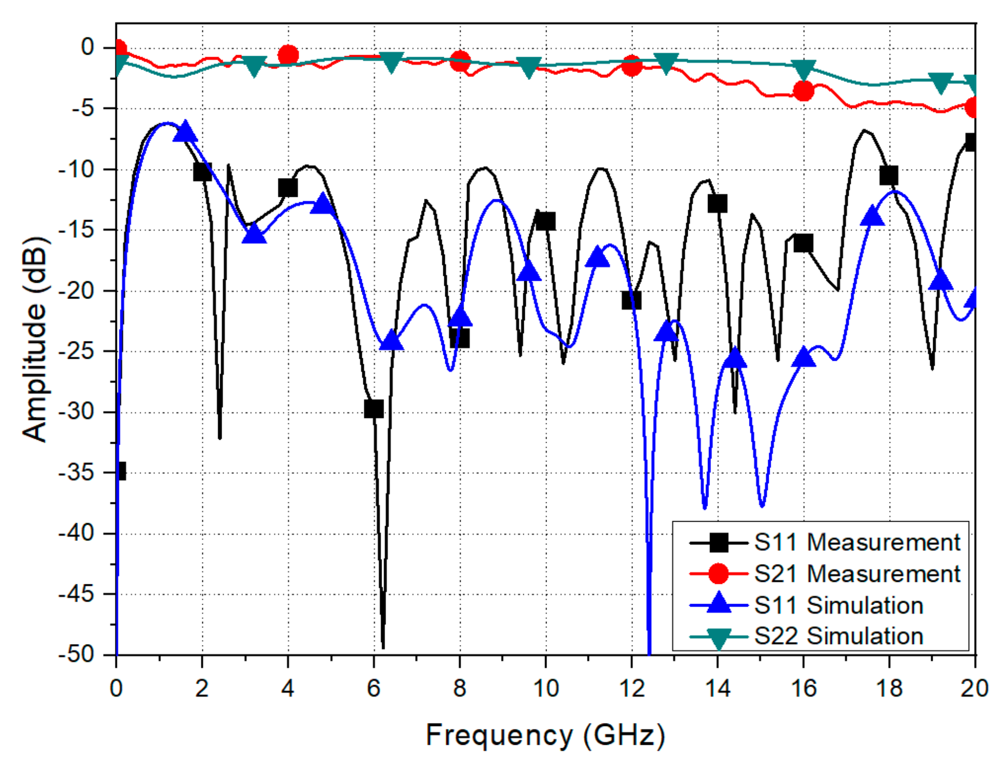
3.2. S-Parameters of the Back-to-Back Structure

In Figure 9, the simulated and measured S-parameters of the back-to-back configuration of the proposed transition are presented. The fabricated bended CPS-to-MSL transition provides less than 1 dB insertion loss per transition from 2 GHz to 14.8 GHz, and less than 2 dB insertion loss per transition from 2 GHz to 17 GHz with more than 10 dB return loss from 2 GHz to 17.2 GHz. The upper operating frequency (up to 17 GHz) is slightly degraded as compared with the bended CPS-to-MSL transition in [18] (up to 20 GHz), which were developed by the authors’ group.
In Table 2, the proposed compact CPS-to-MSL transition is compared with the reported CPS-to-MSL transitions in terms of the characteristic line impedance, operating bandwidth, transition size, analytical model, and dielectric constant of the substrate. In [8], the reported transition obtained wide bandwidth using a long-modified ground plane, of which the shape was obtained through parameter tuning trials. In the back-to-back structure in [8], a long CPS line of 26 mm (1024 mil) was used, and thus the start frequency was lowered. However, this start frequency might not be the actual start frequency of the single transition. The performance of the reported transition was measured as a back-to-back structure, consisting of two transitions and a CPS line in-between, but the length of the middle CPS line could affect the start frequency [16]. To clarify the relation between the CPS line length and the start frequency of a back-to-back structure, the simulated S-parameters of the proposed back-to-back CPS-to-MSL transition as varying the CPS length are shown in Figure 10. The proposed back-to-back structure consists of two transitions and a middle CPS line, working as a multi-section impedance transformer that may change the locations of S11 poles. In this case, by increasing the length of the CPS line, the start frequency of the back-to-back transition can be lowered to 1.9 GHz with the CPS length of 14 mm (550 mil) and to 1.6 GHz with the CPS length of 26 mm (1024 mil).
The transitions presented in [9,11,12,13] did not provide wide frequency bandwidth and analytical models. In [15], the wide bandwidth transition with the start frequency of 5.8 GHz was designed on a low dielectric constant substrate with an analytical design formula. The transitions in [10] and [17] showed starting frequencies of 2.3 GHz and 3 GHz, respectively. In [10], the transition length was short due to small impedance difference between the CPS line and MSL. In [17], the transition length was long because of the high CPS line impedance. In [18], a bended CPS-to-MSL transition (reported by the authors’ group), with start frequency of 1.8 GHz, was designed with an analytical model for wide frequency bandwidth (1.8–20 GHz). However, the transition was designed on a single-layered substrate, and the horizontal length of this transition was not sufficiently reduced as compared with the proposed compact transition. Therefore, the proposed bended CPS-to-MSL transition outperforms the reported transitions in terms of length, analytical model, and wideband performance.

4. Conclusions

A compact ultra-wideband CPS-to-MSL transition with a sinusoid-shaped bended structure on a two-layered substrate is presented. The proposed transition consists of a CPS taper and a bended CPS-to-MSL transition on a two-layered substrate. The CPS taper is formed on the lower substrate with low permittivity to feed a W-band balanced antenna/detector, and the bended CPS-to-MSL transition is formed on the upper substrate with high permittivity. The proposed transition is designed with analytical formulas obtained by applying EM-based conformal mapping. The proposed CPS-to-MSL transition optimally connects between a high impedance CPS line (158 Ω) and a 50 Ω MSL, which typically results in very long transition length for wideband performance. The implemented bended transition provides good performance from 2 GHz to 17 GHz, and the horizontal length of the bended transition is reduced to 42.9% of the straight transition length. Even with the structure complexity of the proposed transition, the transition can be efficiently designed by using the EM-based analytical formulas, while this multi-layered bended transition design with the 3D EM optimization trials can be very time-consuming. The proposed bended transition is developed for use in mm-wave balanced antenna/detector feeds but can be applied to a variety of wideband balanced circuit modules, where the horizontal circuit size needs to be reduced.

Author Contributions

Conceptualization, G.H.L. and K.W.K.; methodology, G.H.L.; software, G.H.L.; validation, G.H.L.; formal analysis, G.H.L.; investigation, G.H.L.; resources, G.H.L.; data curation, G.H.L.; writing—original draft preparation, G.H.L., W.M. and S.K.; writing—review and editing, G.H.L., W.M., S.K. and K.W.K.; visualization, G.H.L.; supervision, H.C.C. and K.W.K.; project administration, H.C.C. and K.W.K.; funding acquisition, K.W.K. All authors have read and agreed to the published version of the manuscript.

Funding

This research was funded by the Ministry of Education, Science and Technology and the Ministry of Education, Korea.

Acknowledgments

This research was supported in part by the National R&D Program through the National Research Foundation of Korea (NRF) funded by the Ministry of Education, Science and Technology (No. NRF-2019M1A7A1A03088464) and in part by the BK21 FOUR project funded by the Ministry of Education, Korea (4199990113966).

Conflicts of Interest

The authors declare no conflict of interest.

References

  1. Ma, T.G.; Wang, C.W.; Hua, R.C.; Tsai, J.W. A Modified Quasi-Yagi Antenna With a New Compact Microstrip-to-Coplanar Strip Transition Using Artificial Transmission Lines. IEEE Trans. Antennas Propag. 2009, 57, 2469–2474. [Google Scholar] [CrossRef]
  2. Alhalabi, R.A.; Rebeiz, G.M. Differentially-Fed Millimeter-Wave Yagi-Uda Antennas With Folded Dipole Feed. IEEE Trans. Antennas Propag. 2010, 58, 966–969. [Google Scholar] [CrossRef]
  3. Mandal, M.K.; Chen, Z.N. Compact Dual-Band and Ultrawideband Loop Antennas. IEEE Trans. Antennas Propag. 2011, 59, 2774–2779. [Google Scholar] [CrossRef]
  4. Koziel, S.; Ogurtsov, S.; Zieniutycz, W.; Bekasiewicz, A. Design of a Planar UWB Dipole Antenna With an Integrated Balun Using Surrogate-Based Optimization. IEEE Antenna Wirel. Propag. Lett. 2015, 14, 366–369. [Google Scholar] [CrossRef]
  5. Woo, D.S.; Kim, Y.G.; Cho, Y.K.; Kim, K.W. Ultra-Wideband Fermi Antenna Using Microstrip-to-CPS Balun. IEICE Trans. Commun. 2010, E93-B, 2219–2222. [Google Scholar] [CrossRef]
  6. Dong, Y.; Johansen, T.K.; Zhurbenko, V. Ultra-wideband coplanar waveguide-to-asymmetric coplanar stripline transition from DC to 165 GHz. Int. J. Microw. Wirel. Technol. 2018, 10, 870–876. [Google Scholar] [CrossRef] [Green Version]
  7. Kim, S.; Jeong, S.; Lee, Y.T.; Kim, D.H.; Lim, J.S.; Seo, K.S.; Nam, S. Ultra-wideband (from DC to 110 GHz) CPW to CPS transition. Electron. Lett. 2002, 38, 622–623. [Google Scholar] [CrossRef]
  8. Suh, Y.H.; Chang, K. A wideband coplanar stripline to microstrip transition. IEEE Microw. Wirel. Compon. Lett. 2001, 11, 28–29. [Google Scholar] [CrossRef]
  9. Park, B.; Jeong, M.; Park, S. A Miniaturized Microstrip-to-Coplanar-Strip Transition Loaded with Artificial Transmission Lines and 2.4-GHz Antenna Application. IEEE Antenna Wirel. Propag. Lett. 2014, 13, 1486–1489. [Google Scholar] [CrossRef]
  10. Mandal. M., K.; Chen, Z.N. Compact ultra-wideband microstrip-to-coplanar stripline transitions. In Proceedings of the IEEE MTT-S International Microwave and RF Conference Proceedings, IMaRC, New Delhi, India, 14–16 December 2013. [Google Scholar] [CrossRef]
  11. Simons, R.N.; Dib, N.I.; Katehi, L.P.B. Coplanar stripline to microstrip transition. Electron. Lett. 1995, 31, 1725–1726. [Google Scholar] [CrossRef]
  12. Tu, W.H.; Chang, K. Wide-Band Microstrip-to-Coplanar Stripline/Slotline Transitions. IEEE Trans. Microw. Theory Tech. 2006, 54, 1084–1089. [Google Scholar] [CrossRef]
  13. Chiu, T.; Shen, Y.S. A Broadband Transition Between Microstrip and Coplanar Stripline. IEEE Microw. Wirel. Compon. Lett. 2003, 13, 66–68. [Google Scholar] [CrossRef]
  14. Kim, Y.G.; Woo, D.S.; Kim, K.W.; Cho, Y.K. A New Ultra-wideband Microstrip-to-CPS. In Proceedings of the 2007 IEEE/MTT-S International Microwave Symposium, Honolulu, HI, USA, 3–8 June 2007; pp. 1563–1566. [Google Scholar] [CrossRef]
  15. Lee, G.H.; Mohyuddin, W.; Choi, H.C.; Kim, K.W. Asymmetric Ultra-Wideband Microstrip-to-Coplanar Stripline Transition. IEEE Microw. Wirel. Compon. Lett. 2018, 28, 386–388. [Google Scholar] [CrossRef]
  16. Pozar, D.M. Microwave Engineering; John Wiely & Sons: New York, NY, USA, 1998. [Google Scholar]
  17. Jiang, Q.; Domier, C.; Luhmann, N.C. A Wideband Low Loss Planar Microstrip-to-CPS Balun. In Proceedings of the Asia Pacific Microwave Conference (APMC), Kaohsiung, Taiwan, 4–7 December 2012; pp. 1205–1207. [Google Scholar] [CrossRef]
  18. Lee, G.H.; Kim, D.H.; Mohyuddin, W.; Kumar, S.; Choi, H.C.; Kim, K.W. Wideband bended CPS-to-microstrip transition for millimeter-wave antenna-detector module. Microw. Opt. Technol. Lett. 2020, 62, 1991–1996. [Google Scholar] [CrossRef]
  19. Gupta, K.C.; Garg, R.; Bahl, I. Prakash Bhartia Microstrip Lines and Slotlines; Artech House: London, UK, 1996. [Google Scholar]
  20. Lee, G.H.; Kumar, S.; Mohyuddin, W.; Choi, H.C.; Kim, K.W. Generalized Design Technique of Ultra-Wide-band Transitions for Quasi-TEM Planar Trans-mission Lines Based on Analytical Models. IEEE Access 2021, 9, 52619–52633. [Google Scholar] [CrossRef]
Figure 1. (a) Block diagram of the ECE imaging system, (b) W-band antenna/detector.
Electronics 10 01272 g001
Figure 2. Configuration of the proposed compact CPS-to-MSL transition: (a) perspective view, (b) side view, (c) CPS taper, (d) bended CPS-to-MSL transition on a two-layered substrate.
Electronics 10 01272 g002
Figure 3. Electric field distributions at several cross-sections along the proposed transition.
Electronics 10 01272 g003
Figure 4. Calculated and simulated characteristic line impedances of the CPS taper (AA′ to BB′).
Electronics 10 01272 g004
Figure 5. Cross-sectional model of the two-layered CPS-to-MSL transition with four analysis regions.
Electronics 10 01272 g005
Figure 6. Calculated and simulated characteristic line impedances of the two-layered CPS-to-MSL transition without bending (DD′ to GG′).
Electronics 10 01272 g006
Figure 7. Simulated magnitude of the reflection coefficient of the MSL taper by increasing the physical length L. Here, Γm = 0.02, Γ0 = 0.52.
Electronics 10 01272 g007
Figure 8. Fabricated back-to-back structure of the proposed compact CPS-to-MSL transition: (a) perspective view, (b) top and bottom view.
Electronics 10 01272 g008
Figure 9. Simulated and measured S-parameters of the proposed compact CPS-to-MSL transition.
Electronics 10 01272 g009
Figure 10. Simulated S-parameters of the back-to-back structures as varying the CPS line length. (In the proposed back-to-back transition, a 1.3 mm (50 mil) CPS line is used.).
Electronics 10 01272 g010
Table 1. Design parameters of the proposed compact CPS-to-MSL transition.
w1w2w3g1g2rl1l2
6 mil15 mil8 mil5 mil10 mil77 mil320 mil507 mil
(0.15 mm)(0.38 mm)(0.20 mm)(0.13 mm)(0.25 mm)(2.0 mm)(8.1 mm)(13 mm)
Table 2. Comparison with the reported CPS-to-MSL transitions.
ReferenceInsertion Loss
(Back-to-Back Structure)
Insertion Loss
per Transition
(dB)
Return Loss
(dB)
Operating
Bandwidth
(GHz)
CPS
Line
Impedance
(Ω)
Horizontal
Length
(mil/mm)
Electrical length
in Free Space **
Relative
Dielectric Constant
Analytical
Model
[8]<3<1.5>101.3–13.3 (164%)161 *1181/300.13 λ2.33n/a
[9]<3<1.5>101.3–3.2 (84%)1211181/300.13 λ4.4n/a
[10]<2.6<1.3>102.3–15.4 (148%)1251024/260.20 λ3.38n/a
[11]<2.4<1.2>105.1–6.1 (18%)88276/70.11 λ10.2n/a
[12]<3<1.5>104.7–10.2 (74%)1241496/380.60 λ2.33n/a
[13]<2<1>206.9–12.4 (57%)1402126/541.20 λ3.25n/a
[15]<2<1>105.8–40 (149%)147827/210.40 λ2.2used
[17]<2<1>103–18.5 (144%)1761693/430.43 λ3.38n/a
[18]<2<1>101.8–20 (160%)1581299/330.28 λ3.38used
This work<4<2>102–17 (157%)158827/210.19 λ3.38/10.2used
* The actual CPS line impedance in [8] was calculated as 161 Ω (verified by the CST EM simulator), which is lower than 184 Ω as mentioned in [8]. ** Electrical lengths in free space with respect to the start frequency.
Publisher’s Note: MDPI stays neutral with regard to jurisdictional claims in published maps and institutional affiliations.

