Article

Solid-State DC Circuit Breakers and Their Comparison in Modular Multilevel Converter Based-HVDC Transmission System

by
Gul Ahmad Ludin
1,2,*,
Mohammad Amin Amin
2,
Hidehito Matayoshi
3,
Shriram S. Rangarajan
4,5,
Ashraf M. Hemeida
6,
Hiroshi Takahashi
7 and
Tomonobu Senjyu
1,*
1
Electrical and Electronics Engineering Department, University of the Ryukyus, 1 Senbaru, Nishihara-cho, Nakagami, Okinawa 903-0213, Japan
2
Electrical Power Engineering Department, Kabul Polytechnic University, 5th District, Kabul, Afghanistan
3
Osaka Institute of Technology, Osaka 530-8568, Japan
4
Department of Electrical and Electronics Engineering, SR University, Warangal, Telangana 506001, India
5
Department of Electrical and Computer Engineering, Clemson University, Clemson, SC 29631, USA
6
Electrical Engineering Department, Faculty of Energy Engineering, Aswan University, Aswan 81528, Egypt
7
Fuji Electric Co., Ltd., Tokyo 141-0032, Japan
*
Authors to whom correspondence should be addressed.
Electronics 2021, 10(10), 1204; https://doi.org/10.3390/electronics10101204
Submission received: 3 March 2021 / Revised: 25 April 2021 / Accepted: 14 May 2021 / Published: 18 May 2021
(This article belongs to the Section Industrial Electronics)

Abstract

:
This paper proposes a new and surge-less solid-state direct current (DC) circuit breaker in a high-voltage direct current (HVDC) transmission system to clear the short-circuit fault. The main purpose is the fast interruption and surge-voltage and over-current suppression capability analysis of the breaker during the fault. The breaker is equipped with series insulated-gate bipolar transistor (IGBT) switches to mitigate the stress of high voltage on the switches. Instead of conventional metal oxide varistor (MOV), the resistance–capacitance freewheeling diodes branch is used to bypass the high fault current and repress the over-voltage across the circuit breaker. The topology and different operation modes of the proposed breaker are discussed. In addition, to verify the effectiveness of the proposed circuit breaker, it is compared with two other types of surge-less solid-state DC circuit breakers in terms of surge-voltage and over-current suppression. For this purpose, MATLAB Simulink simulation software is used. The system is designed for the transmission of 20 MW power over a 120 km distance where the voltage of the transmission line is 220 kV. The results show that the fault current is interrupted in a very short time and the surge-voltage and over-current across the proposed breaker are considerably reduced compared to other topologies.

1. Introduction

Renewable energy such as solar and wind power as environmentally friendly and sustainable energy resources have attracted extensive attention in recent years. The HVDC transmission system is a key technology for integrating various AC grids and economic transmission of large-capacity renewable energy for a long distance especially for remote areas [1]. This huge amount of power transmission needs stable and reliable converters with high power capability. Due to the development of semiconductor devices, voltage source converters (VSCs) or self-commutated converters have substantial advantages compared to the current source converters (CSCs) or line commutated converters (LCCs). For instance, in VSC, the active and reactive power can be controlled independently at both ends; reactive power compensation is not needed; VSC has black start capability without additional devices; etc. [2,3]. Classical VSC, which is based on the two and three-level topology, was introduced in 1997 and widely used until 2010. The main drawbacks with this kind of converter are its high switching frequency requirements, large switching losses, and production of high harmonic contents [4,5]. In 2010, the new type of VSC called modular multilevel converter (MMC) was developed by Siemens, which eliminates the aforementioned problems and has several technical and economic advantages as described in [6,7,8].
On the other hand, fault occurrence, especially DC short-circuit fault, is a major challenge in the MMC–HVDC transmission system (MMC having half-bridge sub-modules). The mentioned challenge arises due to the absence of a current blocking function in the converter [9,10]. The rapid rise of fault current due to the fault path low impedance and the high current flow into the fault point may cause system collapse and damage the power converter and other electrical instruments [7,11], since their protection, safety, and efficient life period is directly affected by short-circuit current level.
The essential solution to this issue is the employment of fault current limiters and fast DC circuit breakers (DCCBs) [12]. Generally, a DCCB must fulfill the following basic requirements [13,14,15,16]: acquire a current zero-crossing to cut-off the current; dissipate the energy stored from the system inductance; tolerate the voltage reaction after current disconnection. In VSC-based systems, the HVDC breaker should be able to interrupt instantaneously. Moreover, the peak voltage generated by the breaker should be low enough to satisfy the insulation requirement of the DC system. It is specifically substantial for switching the load currents where the network is at nominal voltage [17].
DCCB can selectively isolate the faulty section without disconnection of the whole HVDC system. It ensures no damages to the system and maintains the stability of the HVDC system. Furthermore, by applying the DC breaker, the number of converters and costs can be reduced accordingly [18,19].
DCCBs are divided into three types: mechanical, solid-state, and hybrid DC circuit breakers [20]. Classical topology based on the mechanical breaker is used in many applications, but its action is not flexible, real-time, and continuous [21]. The breaking operation time is too long (tens of milliseconds) to meet the requirement of fast fault current interruption, and they cannot quickly clear short-circuit faults [22,23]. Hybrid DCCBs are capable of interrupting the fault current within a few milliseconds, but this topology is larger in size, is complex, and has higher capital cost than SSCB, especially in a meshed HVDC grid [23]. In addition, they have limitations in handling large fault currents with increased voltage ratings [24]. In contrast, the solid-state circuit breaker (SSCB) is a fast, flexible, and accurate circuit breaker that is widely used as a key technology in HVDC transmission systems [25,26]. SSCB can quickly switch off the faulty line and delimit the short-circuit current and keep the line voltage to an acceptable range [27]. Several studies have been done in the field of SSCBs. In most cases, the over-voltage arising from sudden cut-off of current and over-current due to switching of the semiconductor devices are the challenging issues. If the withstanding voltage of equipment in the MMC-HVDC system is selected to be very high, troubles in the manufacture of converter equipment will increase accordingly, and as well as the total cost of the system [28]. In [29], a new SSCB with MOV is proposed. Although the fault current is decreased before its interruption by a series connection of current limiting inductors, the interruption time is still long. In addition, the series connection of inductors will increase the complexity and cost of the breaker. A SSCB topology using passive elements for over-voltage suppression has been proposed in [30]. In addition to its unidirectional functionality, the proposed breaker employs coupled inductors. The utilization of these inductors would be challenging for HVDC applications. In [31], a study on the separation of energy absorption branch and over-voltage suppression branch has been conducted. The authors used a small electronics varistor for over-voltage protection and a large power electronics varistor for energy absorption in an SSCB. Two topologies are introduced for SSCB in [32]. One of the topologies uses nonlinear resistors in parallel with the IGBTs to suppress the over-voltage and absorb the released energy. Another topology is equipped with freewheeling diodes in series with nonlinear resistors. The nonlinear resistor is also usually available as an MOV [33]. In references [21,34,35,36], the authors proposed the breakers-equipped MOV to suppress the sudden and unwanted over-voltages in the system. The problem that arises with such protection instrument is the higher energy absorption by surge arrester and the large capacity surge arrester requirement, which increases the total cost. In addition, the response time of MOV against surge-voltage can be slowed down by its inductance. In addition, MOVs known as expensive devices have the aging problems and even possibility of catastrophic failures [37]. The resonance SSCB may still make enable useful applications such as load switching as it has a low resistive on-state loss compared to newer topologies. However, practically, the technology has been proven to be too slow for fault current interruption in the VSC–HVDC systems [13]. Meanwhile, the main challenge is the requirement of an additional resonance circuit for providing the zero-cross point that increases the complexity and costs of the breaker.
This paper proposes a new and surge-less SSCB in an MMC-HVDC transmission system. To maintain the same voltage balancing, the CB practically consists of many (in this study two) series IGBTs, making it possible to apply it for high-voltage applications. The CB also has the advantage of a fast turn-off capability that makes it possible to rapidly cut-off and prohibit the extension of the fault. Instead of traditional MOVs, the resistance–capacitance freewheeling diodes branch is used in the breaker to suppress the over-voltage and clear the residual charge and risk of over-voltage on the line during the fault. The breaker is also without the auxiliary circuit for providing the zero-cross point and does not have any mechanical parts. To prove the effectiveness of proposed SSCB, simulation has been done for two other SSCB topologies called LC resonance semiconductor DC breaker and solid-state DC circuit breaker with a freewheeling diode. These topologies have been compared based on surge-voltage and over-current suppression arising from fault current interruption and reconnection of semiconductor devices, respectively. The rest of the paper is organized as follows: In Section 2, the configuration of the overall system is described. Control methods of MMC are presented in Section 3. Different CB topologies including the proposed circuit breaker are presented in Section 4. The control strategy of the proposed breaker is discussed in Section 5. The operation principle of proposed breaker is described in Section 6. Section 7 presents the energy absorption capability of the proposed breaker. Section 8 details the parameters design of the breaker. Simulation results are exhibited in Section 9. Finally, Section 10 and Section 11 present the discussion and conclusion, respectively.

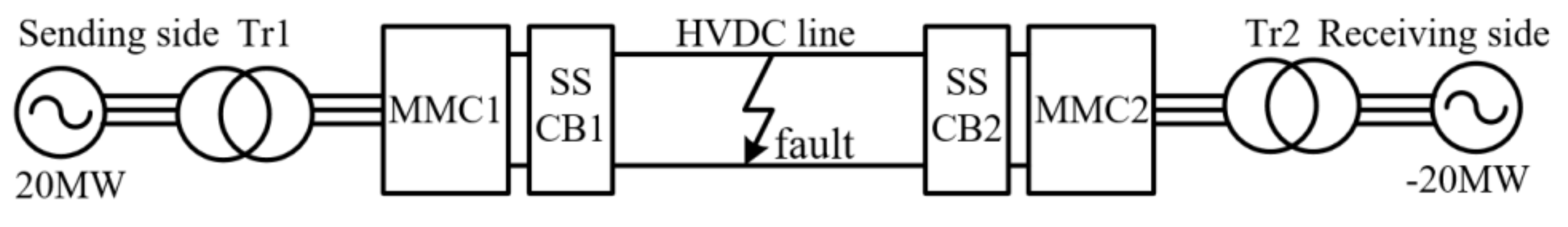
2. System Configuration
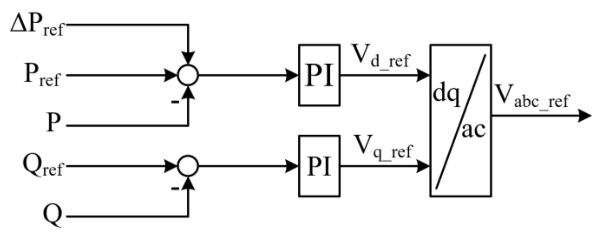
The general configuration of the proposed symmetrical three-phase MMC-HVDC transmission system is shown in Figure 1. The DC breaker is placed at both terminals of the DC line. MMC topology is depicted in Figure 2. The MMC consists of six symmetrical arms. Each arm has a series connection of N (for the simulation in this research, N = 2) nominally identical sub-modules (SMs) and an inductor. A sub-module consists of two IGBT switches T1 and T2 and a capacitor C. Due to the advantages such as simple structure and being economical and practical [38], this research is based on the half-bridge type of MMC. More details related to MMC design, applications, and control can be found in [2,39,40].

3. Control Methods

The control arrangements of the MMC are shown in Figure 3, Figure 4, Figure 5, Figure 6, Figure 7 and Figure 8 [8]. Figure 3 illustrates the active and reactive power control diagram based on the d-q transformation system. The MMC can control the active and reactive power independently. To guarantee the actual active and reactive power, the average voltage value of the upper and lower arm capacitor is controlled to the reference values, as shown in Figure 4. In addition, by balancing this voltage, it is conceivable to optimally utilize the stored energy and evenly distribute power losses to the installed electrical devices while avoiding the concentration of thermal stress on particular modules of the converter [41]. The DC-link voltage control system is depicted in Figure 5. In MMC, the DC-link capacitor is eliminated; therefore, the DC-line voltage is controlled directly and faster. The arm current control loop is shown in Figure 6. Upper and lower arm currents are compared with each other. If the DC component in the arm is higher or lower than the reference value, then an error is fed into the controller for compensation. Furthermore, with transformer or transformerless schemes, if an asymmetrical fault occurs, there will be significant zero-sequence components of voltage in both arms of the converter. This matter can generate a large zero-sequence current, which transmits to the DC side, and as a result, it will increase the rated current of the DC-link [2]. To avoid this, the zero-sequence current-eliminating controller is proposed as shown in Figure 7. The gating signal of each sub-module is achieved by using the pulse width modulation (PWM) technique. The technique is based on the phase-shifting method, i.e., comparison of the reference signal to the triangular multi-carrier signal. The gating (switching) signal is given by:
N i = 0.5 + n i 2
where n represents the reference signal given to the PWM generator.
Finally, the combination of three command values n1, n2, and n3, is given to the PWM generator to generate switching signals, as shown in Figure 8. The carrier frequency is 1 kHz.

4. Solid-State HVDC Breaker Topologies

This section presents a brief functional assessment and the circuit configuration of two recent solid-state CBs and proposed topology.

4.1. LC Resonance Semiconductor DC Breaker

Figure 9 demonstrates the circuit configuration of the LC resonance circuit breaker that is applied at both sides of the MMC-based HVDC transmission system. The breaker is composed of an LC resonance circuit for resonance current generation to enable the zero-cross point, anti-parallel thyristors for bypassing the fault current, IGBT switch, and also snubber circuit for surge repressing.
During usual operation, the current flows through the IGBT switch S (usual current direction). When a short-circuit fault occurs in the DC link, the current increases, and anti-parallel thyristors Tre (the commutation path) turn on, and the capacitor Cre becomes discharged. At this time, the current fluctuation is generated that provides the zero-crossing point by conducting the reverse current with respect to the fault current. When the current zero-cross point is satisfied, the thyristor Ta turns on, and the breaker cuts off. Finally, the fault current discharges through resistor Ra (the energy absorption path), and the remaining magnetic energy dissipates in the system. Details of the breaker can be found in [42], where it is applied for a two-level VSC-based HVDC system.

4.2. Solid-State DC Circuit Breaker with a Freewheeling Diode

Figure 10 illustrates the circuit scheme of a solid-state DC circuit breaker with a freewheeling diode. The breaker comprises of series IGBTs and reverse conducting diodes that enable the bidirectional power flow in the system. To enable the high-voltage blocking capability, the breaker and freewheeling diode consist of many devices such as resistors RS and RD to maintain the voltage balancing in steady-state, CS capacitors to maintain the voltage balancing in transient conditions and mechanical breaker Sd for keeping the line voltage close to the ground voltage during the breaker opening. When a short-circuit fault occurs in the DC line, the current is increased and discharges to the fault point. The current raise is detected, and S1 and S2 are turned off. The fault current commutates to snubber capacitors Cs. When Cs is charged, the freewheeling diode turns on, and finally, inductor L is demagnetized through varistor RV, and the fault is cleared.
In this topology, there is no need for an extra circuit to provide the zero-crossing point, and the pressure of high voltage is decreased by connecting several series IGBTs. More details about the solid-state DC circuit breaker with a freewheeling diode can be found in [32], in which it is implemented in a two-level VSC-HVDC transmission system.

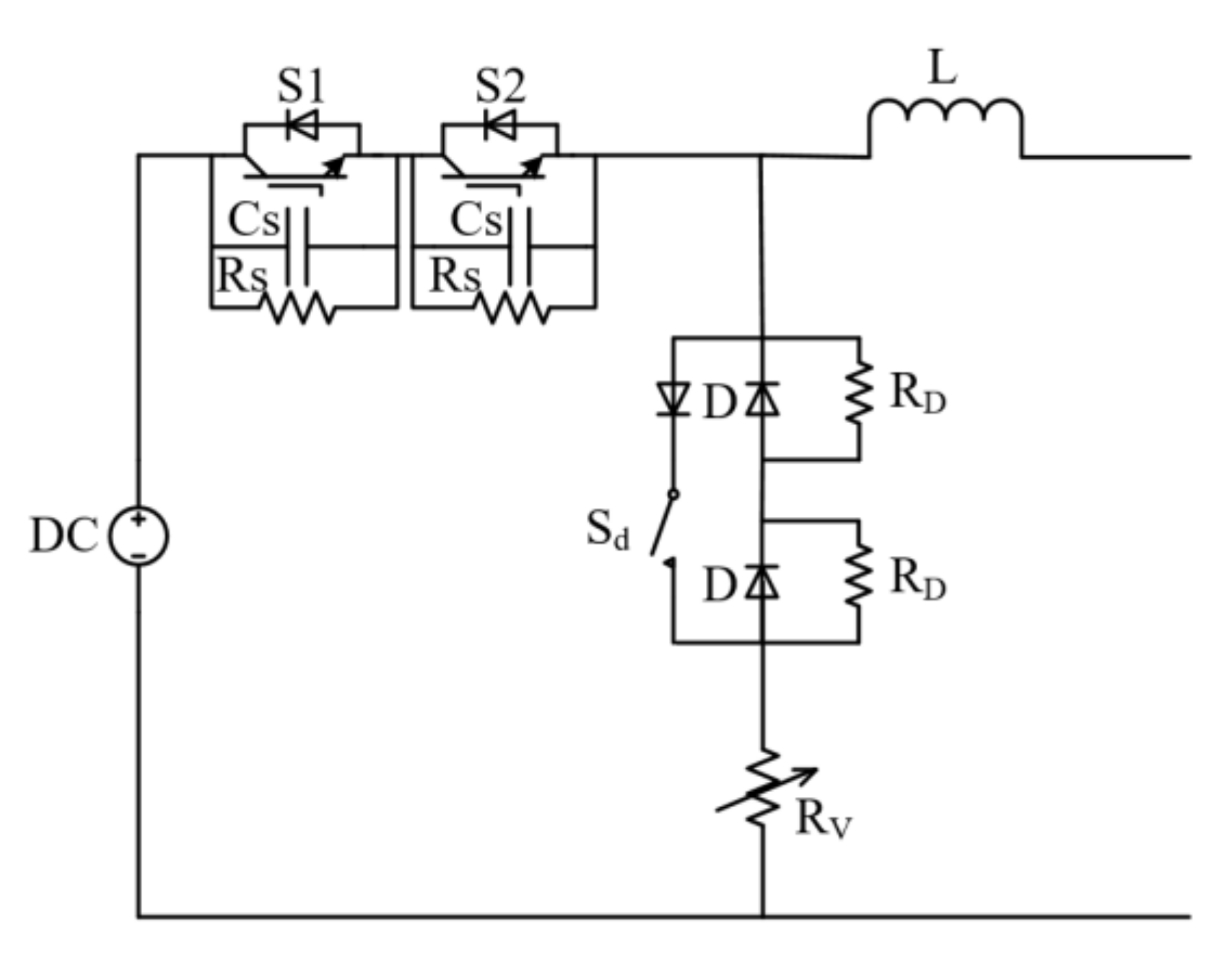
4.3. Proposed Breaker Topology

Figure 11 shows the single line diagram of the proposed solid-state DC circuit breaker. The breaker consists of series IGBTs and the reverse conducting diodes to provide bi-directional power flow in the transmission line. Several IGBT switches (for the simulation in this study, two: S1 and S2) are connected in series to maintain equal voltage balancing, enable high-voltage blocking, and make it possible for high-voltage applications. Snubber resistors (Rs) and capacitors (Cs) are connected in parallel with S1 and S2 to sustain voltage balancing for series switches in steady and transient states, respectively. The resistance–capacitance branch (RC) and diode bridge (D1, D2, D3, and D4) are used to bypass the high fault current, suppress the current breaking over-voltage, and eliminate the remaining charge on the line. The gate turn-off thyristor (GTO) as a fast controllable semiconductor device is used to control the resistance–capacitance branch during the fault [25]. The zero-cross point is made naturally by commutating the current to snubber capacitors (Cs).

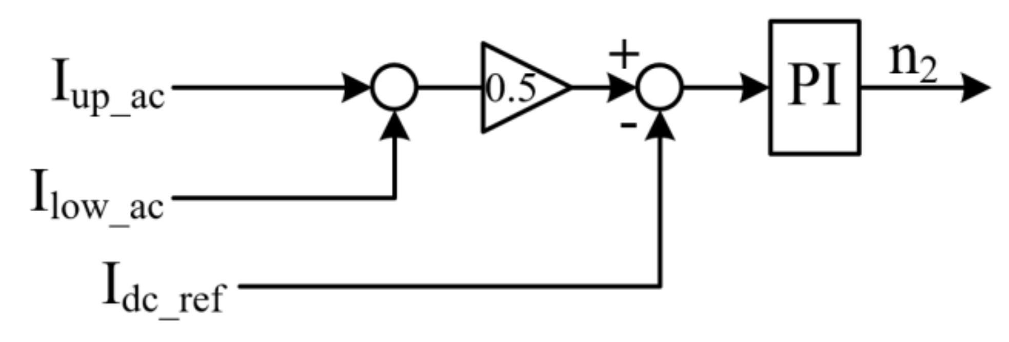
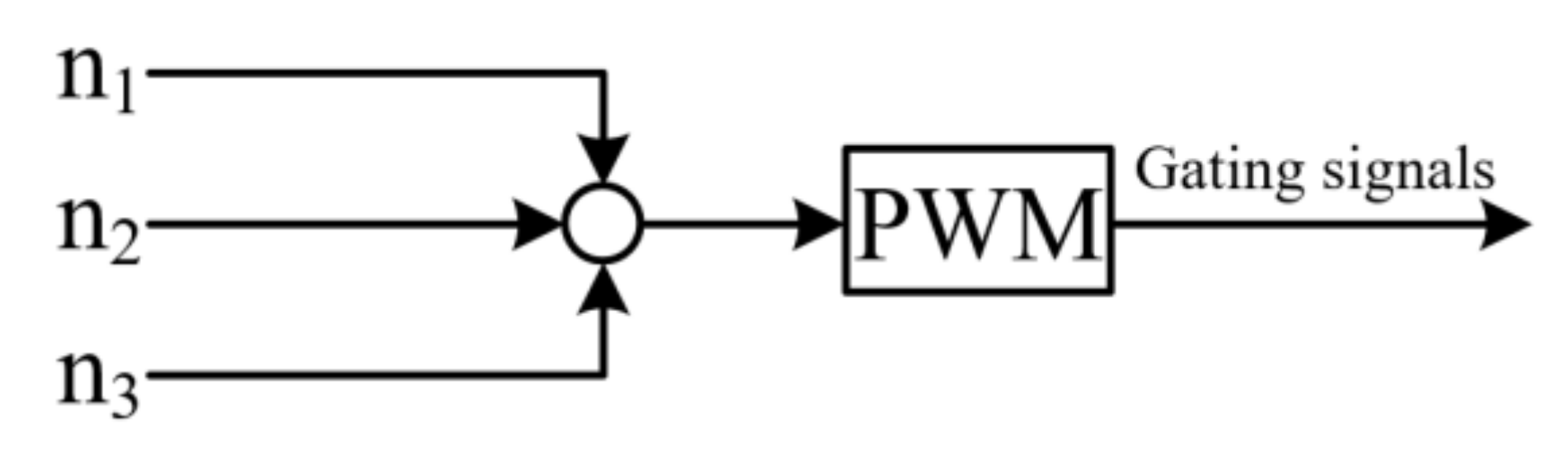
5. Proposed Breaker Control Strategy

The control block diagram of the proposed breaker operation during fault occurrence is shown in Figure 12. Figure 13 explains the handling stages of fault current with respect to time. The synchronous voltage and current signal from both sides of the HVDC line is regularly checked. When the voltage and current signal are normal at both sending and receiving sides, then the breaker continues normal operation. The period 0 ≤ t ≤ t1 in Figure 13 is considered as a normal working period. The breaker control system can recognize the normal voltage and current signal and use it as a synchronization reference signal. The t1 ≤ t ≤ t2 is a transient period when fault occurs. In this period, the current starts to increase from the rated value. When current increases to a predefined threshold value, the commutation mode will be executed by sending turn-off signals to IGBTs. The interval t2 ≤ t ≤ t3 is the commutation period. The snubber capacitors will be charged, and thereafter, the freewheeling diodes will be turned on to conduct the fault current to the RC branch. When the fault current is dissipated through GTO in the RC branch and reached zero, the breaker will be reclosed by the controller. During the conduction state, GTO behaves identical to a thyristor. As a semi-controlled device, it turns on by applying a gate signal and turns off just when the inductor current reaches zero by its dissipation in the RC branch. The GTO is equipped with snubbers, i.e., a resistor and capacitor, which are connected in parallel with GTO to absorb the voltage fluctuation that occurs when it turns off the current.

6. Proposed SSCB Operation Principle

To explain the operation of the proposed breaker, short circuit fault is assessed in the transmission line where the power flow direction is from MMC1 in rectifier operation to MMC2 in inverter operation. The short-circuit fault characteristic in a half-bridge MMC–HVDC transmission system can be found in [12,43]. The operation of the breaker can be divided into four operation states i.e., normal state, fault occurrence state, breaking or commutation state, and demagnetizing state.
The operation principle of the proposed breaker and transition process of the current direction from one state to another at both the sending and receiving side is depicted in Figure 14. Figure 14a indicates the current flowing in normal operation before fault occurrence. In this state, S1 and S2 switches at both sides remain in the on state, and freewheeling diodes are off. Hence, the current flows stably through the main path of the breaker i.e., IGBTs valves at the sending end and reverse conducting diodes at the receiving end. Figure 14b shows the current direction when a short circuit fault happens in the DC line. In this case, the current increases rapidly at the sending side. When the current became larger than the predefined threshold value, it is detected as a fault, and the interruption process starts with opening the S1 and S2. Simultaneously, the fault current is commutated to charge the snubber capacitors Cs. Contrariwise, at the receiving side, as a part of the current flows through the fault point, so the current of inductor L decreases. The current decrease is detected, and the control signal of the transistor turns off. As no forward current flows through S1 and S2 of the SSCB2, therefore, no state change happens at this time. When the inductor current reaches zero, the reverse diodes turn off, and the current commutates to charge the snubber capacitors. The current flow direction during charging the snubber capacitors of SSCB1 and SSCB2 is shown in Figure 14c. Fault current can be calculated by Equation (2) [42].
I d c t = I d c 0 + V d c L d c t
where I d c 0 is the line rated current, V d c is the rated voltage, L d c represents the inductance of the DC line, and t is the time.
When the capacitors are fully charged, the freewheeling diodes turn on, as illustrated in Figure 14d. The stored energy in the capacitors and line inductance is naturally dissipated with zero-crossing in the RC branch of the breakers and fault impedance. Finally, the capacitors are discharged, the fault current is removed, and also, the inductance L is demagnetized by RC through a fast GTO switch.

7. Energy Absorption Capability of the Proposed Breaker

In the AC systems, the energy absorption at current zero is equal to zero because the current in the main circuit is zero. Contrariwise, in DC systems during fault occurrence, when the CB is turned off, the current is not zero, and there will be significant energy stored in the circuit [44].
According to the proposed breaker topology in this paper, when short-circuit fault occurs, the S1 and S2 switches at both sides will be turned off, and Vdc will not supply any power. Hence, the energy absorption in the DC breaker only consists of energy stored in the line inductance L. This energy generated by the current I0 is given by Equation (3) [45,46].
W L = 1 2 L d c · I 0   2 = 1 2 0.159 × 10 3 × 712.36 2 = 40.342   J o u l e
where I 0 is the amplitude of fault current.

8. Parameters Design of the Proposed Breaker

In order to calculate the parameters, a 220 kV SSCB based on series connected IGBTs is developed for the proposed transmission system to achieve the current breaking capability. The snubber resistor Rs paralleled with IGBT is used for static voltage balance, and Cs is used to address the dynamic voltage balancing problem [47]. The total inductance of the DC line is 19.08 mH (0.159 mH/km). The total delay time from starting the current increasing until the IGBT’s turn off is assumed to be 50 µsec. The increase of inductor current during the delay time is given [32]:
Δ I d c = V d c · T d e l a y L = 220 × 10 3 × 50 × 10 6 19.08 × 10 3 = 576   A .
The rated current of HVDC line is:
I r a t e d = P r a t e d V d c r a t e d = 20 × 10 6 220 × 10 3 = 90.09   A .
Considering the 90.09 A rated current and assuming the protection level is 150%, the over-protection level current is obtained to be 136.36 A. Hence, the required turn-off rating of the breaker is 712.36 A by adding the inductor increasing current Δ I d c .
The total difference in IGBTs turn-off time Δ t o f f can be assumed to be 0.5 μsec. The charging time of the snubber capacitors is designed to be 5 μsec, which is larger than the difference in turn-off time by a factor of 10. Therefore, the snubber capacitance to meet the condition is given by [48]:
C S = Δ t o f f · I t u r n o f f 10 % · V d c = 0.5 × 712.36 10 % · 220,000 = 0.01   μ F .
The remained stored energy in Cs needs to be released totally during the on state of IGBT, and the on-state time ton must be greater than the discharge time when the capacitor voltage drops to zero. Assuming the ton = 25 μsec, the snubber resistor is calculated as follows [49]:
R S = t o n 5 · C S = 25 5 × 0.01 = 500   Ω .
According to the stored energy in L, the branch resistor is calculated as:
R W L I t u r n o f f 2 · t d = 40.342 712.36 2 × 1 × 10 6 = 79.5   Ω
where td is the energy dissipation time. The branch resistor R is selected to be 100 Ω.
According to Figure 11, the RC branch is the series connection of resistor R and capacitor C. By applying the KVL, the exact value of C can be obtained as:
V d c = V R + V C = I R + Q C
where Q is the charge of the capacitor, and it is given by:
Q = C V b [ 1 e t R C ] .
The rate of charging is typically described in terms of a time constant RC. The capacitor C value is adjusted to be 10 µF for the simulation. The breaker parameters are summarized in Table 1.

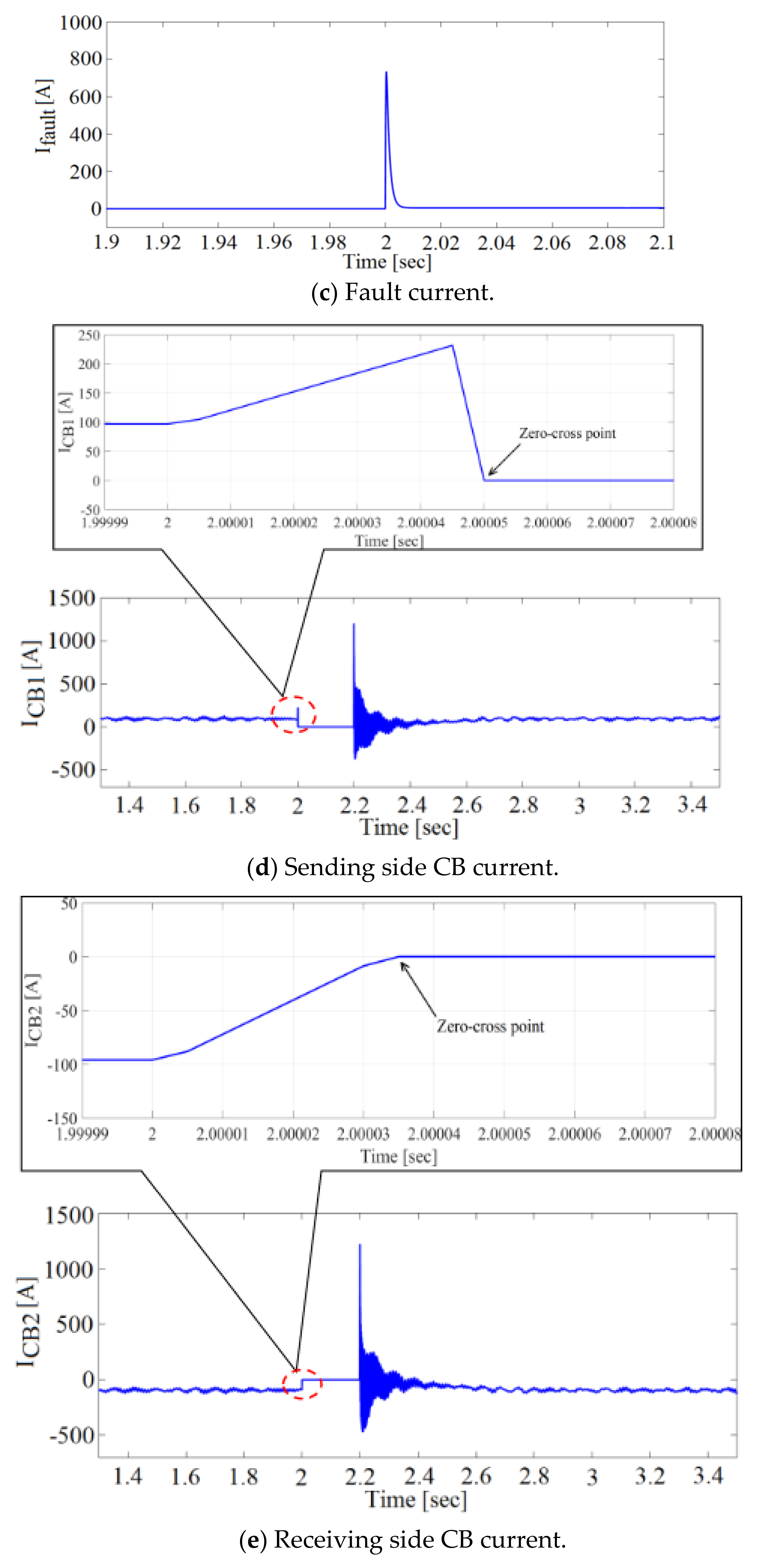
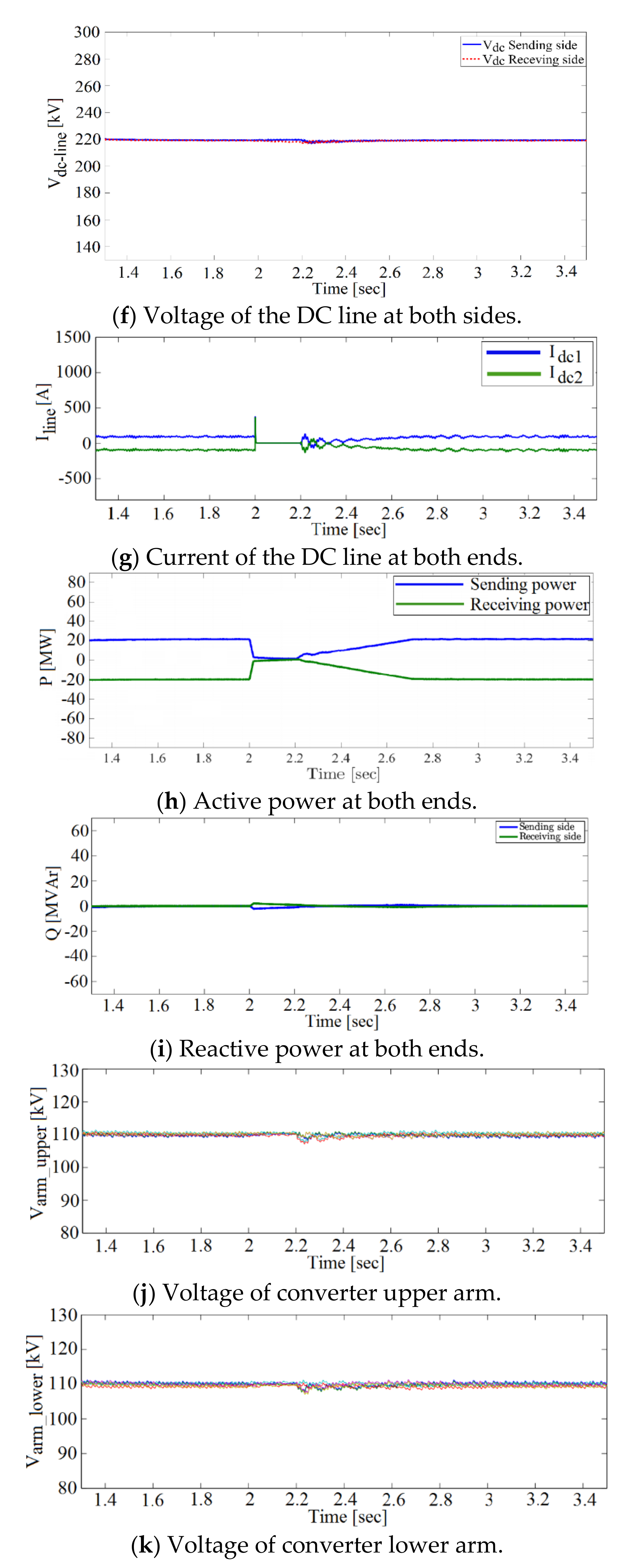
9. Simulation Results

To clarify the comparison between different solid-state breaker topologies presented in Section 4 and show the effectiveness of the proposed breaker over others, simulation is carried out in MATLAB Simulink software. This case study has been done for the transmission of 20 MW power from MMC1 to MMC2 when a short-circuit fault occurs in the DC line. The MMC-HVDC parameters are listed in Table 2. The fault detection method is based on the comparison of voltage and current in the DC link with their rated values, as shown in Figure 15. At 2 sec, the short-circuit fault occurs in the DC line and is detected. After 0.2 sec, the fault is cleared, and the system is returned to the normal operation.
Simulation results for the first topology (LC resonance breaker) are shown in Figure 16. Figure 16a,b show the voltage waveform of the sending and receiving side breakers, respectively. Figure 16c depicts the fault current. Figure 16d,e illustrate the current waveform of the sending and receiving side breakers, respectively. During the normal conditions, the current flows through the usual current direction from MMC1 to MMC2. When fault occurs at 2 sec, the fault currents flow from both sides to the fault point. At this moment, fault is detected when the current reaches its threshold value. After fault detection, the turn-on signal is sent to Tre of the breaker. At this moment, the reverse current with respect to the fault current is injected, which generates current fluctuation in order to achieve the zero-cross point, as shown in Figure 16d. When this point is achieved, the Ta turns on and the breaker turns off. Due to fast turn off of the breaker, a surge-voltage of about 243 kV and 248 kV across each breaker and a fault current of about 850 A appear, as shown in Figure 16a–c. As the DC link nominal voltage is 220 kV, during the fault period, the voltage is kept at a rated value to prevent the overall system disconnection. Simultaneously, due to the reconnection of a semiconductor breaker at both sending and receiving sides, a high over-current i.e., 10120 A and 10050 A, respectively has appeared through the switches. The over-current waveforms are shown in Figure 16d,e.
Figure 17 illustrates the simulation results of using second topology (solid-state breaker with freewheeling diode). Figure 17a,b show the voltage across each switch of the breaker, which is 110 kV. As the response time of the MOV against surge-voltage is not standardized, it can be slowed down by factors such as the inductance of component. Hence, when fault occurs at 2 sec, a high surge-voltage has appeared during the interruption of IGBTs, which increased the rated voltage of SSCB1 and SSCB2 to 143 kV and 129 kV, respectively. Fault current at the time of interruption is illustrated in Figure 17c. Likewise, after the fault clearing by demagnetization of inductance L through varistor RV, the breakers reconnect the DC line by sending the turn-on signal to the IGBTs. At this moment, high over-currents i.e., 4400 A and 4365 A, appeared across the breakers. Figure 17d,e demonstrate the current waveforms of both side breakers during their reclosing.
Simulation results of the proposed circuit breaker are illustrated in Figure 18. Figure 18a,b show the voltage of the breakers at both ends. The fault current is plotted in Figure 18c. Figure 18d,e show the current waveform of both side breakers, respectively. During the normal conditions, the current flows from MMC1 to MMC2. Fault is occurred at 2 sec, and the current of the DC line is increased. This current flows from both sides to the fault point. When the current reaches its predefined threshold value, it is detected as a fault. At this moment, the current is interrupted from IGBTs and commutated to snubber capacitors. Due to the fast turn-off characteristic of IGBTs, the undesired surge-voltage appears, as shown in Figure 18a,b. As the dc line nominal voltage is 220 kV, during the fault duration, the breaker maintains the voltage and prevents the overall system disconnection. As the switches are off, therefore, while charging the snubber capacitors, the current is decreasing until it reaches zero. At this moment, the zero-crossing point is satisfied, as shown in Figure 18d,e. Meanwhile, after enough charging the snubber capacitors, the freewheeling diodes turn on, and the stored energy in the capacitors naturally dissipates in the RC circuit. Likewise, when the fault current is decreased to the threshold value by its dissipation in the RC circuit, the turn-on signal is sent to the S1 and S2 to continue the power flow. Simultaneously, due to the reconnection of semiconductor switches S1 and S2 at both sides, the over-current appears through the switches, as shown in Figure 18d,e. The surge-voltage and over-current should be small enough to prevent equipment damage and comply with the insulation requirements and useful life cycle of the system.
The remaining results of using the proposed circuit breaker are also presented to further clarify the proper working of the proposed breaker during the fault occurrence in the DC line. Figure 18f illustrates the voltage of the DC link at both ends, which is kept constant, i.e., 220 kV. Figure 18g displays the current waveform of the DC line. When fault occurs, the fault current is detected and fallen from its rated value i.e., 90.9 A to zero by commutating to the snubber capacitors. At 2.2 sec, when the breaker is reconnected, the current is restored back to its rated value. Figure 18h depicts the AC side sending and receiving active power and 18i shows the controlled reactive power at both ends. When the current is forced to zero, the active power also decreases from 20 MW to 0 MW and the reactive power is controlled to be 0 MVAr to attain high efficiency. Finally, Figure 18j,k illustrate the upper and lower arms voltage waveform of the MMC. The voltage across converters valves during the fault is also kept constant, i.e., 110 kV at each arm.

10. Discussion

According to simulation results in Section 9, Table 3 summarizes the actual values of surge-voltage, over-current, fault current, and its interruption time for each SSCB topology studied in this paper.
As in the proposed SSCB and also SSCB with a freewheeling diode, two IGBT switches are connected in series for the simulation and the nominal voltage of the HVDC line is 220 kV; therefore, the voltage of each switch is 110 kV. In LC resonance CB, there is one IGBT switch; hence, its nominal voltage is 220 kV. As it is evident from simulation results and Table 3, at the moment of fault occurrence and high breaking speed, the surge-voltage of the proposed SSCB1 and SSCB2 is respectively 118 kV and 117 kV (increasing only 8 kV and 7 kV from its rated value). It shows that the surge-voltage of the proposed CB during current interruption is considerably smaller than other topologies. In addition, the over-currents during the reclosing of IGBTs are respectively 1200 A and 1221.5 A. It shows almost eight and four times less than the first and second CB topologies. Although the fault current of SSCB with a freewheeling diode is lower compared to other topologies, the arc generated during the current interruption can cause adverse effects and problems such as higher energy absorption and losses in the system. In addition, the challenge with using this CB topology is its lower efficiency in terms of suppressing surge-voltage and over-current due to using traditional MOV. However, the fault current interruption time is considerably small, i.e., 5 µsec and is the same in all three topologies, because the structure of the main branch of the breaker equipped with fast IGBTs is same for all topologies. By applying the proposed circuit breaker equipped with the resistance–capacitance freewheeling branch and fast GTO switch, the surge-voltage and over-current is extremely reduced compared to two other topologies. In addition, as it is clear from the results in Figure 18, the DC line voltage during the fault is kept constant with proposed breaker. Furthermore, the reactive power is controlled to be zero, which prevents the power and voltage losses. Therefore, the overall efficiency and quality of the voltage and transmission active power is assured. Moreover, the system could return to normal operation in a short time and without disconnection of the converter stations.

11. Conclusions

This paper has provided the circuit configuration of a new solid-state DC circuit breaker and its operation in an MMC–HVDC transmission system. DC short-circuit fault has been applied, and the proposed breaker were compared to two other recent surge-less SSCB topologies through simulation results. The comparison was based on their surge-voltage and over-current suppression capability during the fault. It was observed that by applying the proposed SSCB, fault current is interrupted in a short time. The surge-voltages and over-currents are extremely reduced compared to other topologies. The power transmission is restored without disconnection of converter stations. Furthermore, since the proposed SSCB does not need the auxiliary circuit for providing zero current-cross point and also has no mechanical parts, therefore, the complexity and cost of the breaker can also be reduced. Moreover, due to having small surge-voltage and over-current, the insulation level of the equipment would be decreased, accordingly.
As a conclusion, this topology of the circuit breaker is suitable and feasible for high-voltage DC applications such as for a multi-terminal HVDC transmission system and the connection of strong AC networks with bi-directional power flows. As a future study, it is essential to execute experiments with actual equipment based on the proposed circuit breaker in a multi-terminal MMC-HVDC transmission system.

Author Contributions

Conceptualization, T.S. and G.A.L.; methodology, G.A.L.; software, H.T.; validation, G.A.L. and M.A.A.; investigation, G.A.L.; resources, H.M.; writing—original draft preparation, G.A.L.; writing—review and editing, S.S.R., and M.A.A.; visualization, A.M.H.; supervision, T.S.; project administration, T.S. All authors have read and agreed to the published version of the manuscript.

Funding

This research received no external funding.

Conflicts of Interest

The authors declare no conflict of interest.

References

  1. van Hertem, D.; Ghandhari, M. Multi-Terminal VSC HVDC for the European Supergrid: Obstacles. Renew. Sustain. Energy Rev. 2010, 14, 3156–3163. [Google Scholar] [CrossRef]
  2. Guan, M.; Xu, Z. Modeling and Control of a Modular Multilevel Converter-Based HVDC System Under Unbalanced Grid Conditions. IEEE Trans. Power Electron. 2012, 27, 4858–4867. [Google Scholar] [CrossRef]
  3. Belda, N.A.; Smeets, R.P.P. Test Circuits for HVDC Circuit Breakers. IEEE Trans. Power Deliv. 2017, 32, 285–293. [Google Scholar] [CrossRef]
  4. Beddard, A.; Barnes, M. Modelling of MMC-HVDC Systems—An Overview; Elsevier: Amsterdam, The Netherlands, 2015; Volume 80, pp. 201–212. [Google Scholar]
  5. Abildgaard, E.M.; Molinas, M. Modelling and Control of the Modular Multilevel Converter (MMC); Elsevier: Amsterdam, The Netherlands, 2012; Volume 20, pp. 227–236. [Google Scholar]
  6. Gnanarathna, U.N.; Gole, A.; Jayasinghe, M.R.P. Efficient Modeling of Modular Multilevel HVDC Converters (MMC) on Electromagnetic Transient Simulation Programs. IEEE Trans. Power Deliv. 2011, 26, 316–324. [Google Scholar] [CrossRef] [Green Version]
  7. Gowaid, I.A. A Low-Loss Hybrid Bypass for DC Fault Protection of Modular Multilevel Converters. IEEE Trans. Power Deliv. 2016, 32, 599–608. [Google Scholar] [CrossRef] [Green Version]
  8. Li, W.; Gregoire, L.-A.; Blanger, J. Control and Performance of a Modular Multilevel Converter System. In Proceedings of the Conference on Power Systems, Halifax, NS, Canada, 6–8 September 2011. [Google Scholar]
  9. Jiang, X.; Bakran, M.-M. Fault Handling Methods and Comparison for Different DC Breaker Topologies and MMC Topologies of the HVDC System. Hindawi Adv. Power Electron. 2018, 2018, 2719380. [Google Scholar] [CrossRef] [Green Version]
  10. Song, Q.; Zeng, R.; Yu, Z.; Liu, W.; Huang, Y.; Yang, W.; Li, X. A Modular Multilevel Converter Integrated with DC Circuit Breaker. IEEE Trans. Power Deliv. 2018, 33, 2502–2512. [Google Scholar] [CrossRef]
  11. Li, R.; Fletcher, J.E.; Xu, L.; Williams, B.W. Enhanced Flat-Topped Modulation for MMC Control in HVDC Transmission Systems. IEEE Trans. Power Deliv. 2016, 32, 152–161. [Google Scholar] [CrossRef] [Green Version]
  12. Miyara, R.; Nakadomari, A.; Matayoshi, H.; Takahashi, H.; Hemeida, A.M.; Senjyu, T. A Resonant Hybrid DC Circuit Breaker for Multi-Terminal HVDC Systems. Sustainability 2020, 12, 7771. [Google Scholar] [CrossRef]
  13. Mobarrez, M.; Kashani, M.G.; Bhattacharya, S. A Novel Control Approach for Protection of Multi-Terminal VSC Based HVDC Transmission System. IEEE Trans. Ind. App. 2016, 52, 4108–4116. [Google Scholar] [CrossRef]
  14. Wu, Y.; Wu, Y.; Rong, M.; Yang, F. Development of a Novel HVDC Circuit Breaker Combining Liquid Metal Load Commutation Switch and Two-Stage Commutation Circuit. IEEE Trans. Ind. Electron. 2018, 8, 6055–6064. [Google Scholar] [CrossRef]
  15. Du, C.; Wang, C. Review of DC Circuit Breaker Technology for HVDC Application. In Proceedings of the IEEE 22nd International Conference on Electrical Machines and Systems (ICEMS), Harbin, China, 11–14 August 2019. [Google Scholar]
  16. Franck, C. HVDC Circuit Breakers: A Review Identifying Future Research Needs. IEEE Trans. Power Deliv. 2011, 26, 998–1007. [Google Scholar] [CrossRef] [Green Version]
  17. Thakur, H. HVDC Circuit Breaker: A Review on Challenges and Innovations. Int. J. Electr. Eng. Technol. 2015, 6, 7–17. [Google Scholar]
  18. Wen, W.; Huang, Y.; Al-Dweikat, M.; Zhang, Z.; Cheng, T.; Gao, S.; Liu, W. Research on Operating Mechanism for Ultra-fast 40.5kV Vacuum Switches. IEEE Trans. Power Deliv. 2015, 30, 2553–2560. [Google Scholar] [CrossRef]
  19. Bucher, M.K.; Franck, C.M. Contribution of Fault Current Sources in Multiterminal HVDC Cable Networks. IEEE Trans. Power Deliv. 2013, 28, 1796–1803. [Google Scholar] [CrossRef] [Green Version]
  20. Tapia, L.; Etxaburu, I.B.; Valera, J.J.; Ruiz, A.S.; Abad, G. Design of a Solid-State Circuit Breaker for a DC Grid-Based Vessel Power System. Electronics 2019, 8, 953. [Google Scholar] [CrossRef] [Green Version]
  21. Eriksson, T.; Backman, M.; Halen, S. A Low Loss Mechanical Breaker for HVDC Grid Applications; CIGRE: Paris, France, 2014. [Google Scholar]
  22. He, Z.; Hu, J.; Lin, L.; Zeng, R. Mechanical DC Circuit Breakers and FBSM-Based MMCs in a High-Voltage MTDC Network: Coordinated Operation for Network Riding through DC Fault. In Proceedings of the International Conference on Renewable Power Generation, Beijing, China, 17–18 October 2015. [Google Scholar]
  23. Zhou, M.; Xiang, W.; Zuo, W.J.; Lin, W.; Wen, J. A Novel HVDC Circuit Breaker for HVDC Application; Elsevier: Amsterdam, The Netherlands, 2019; Volume 109, pp. 685–695. [Google Scholar] [CrossRef] [Green Version]
  24. Ahmad, M.; Wang, Z. A Hybrid DC Circuit Breaker with Fault-Current-Limiting Capability for VSC-HVDC Transmission System. Energies 2019, 12, 2388. [Google Scholar] [CrossRef] [Green Version]
  25. Zhu, L.; Zheng, Y. The Study on New Solid-State Breaker and Its Over-voltage Suppression Technique. Sci. Res. Energy Power Eng. 2013, 5, 1249–1252. [Google Scholar] [CrossRef]
  26. Ding, C.; Nie, T.; Tian, X.; Chen, T.; Yuan, Z. Analysis of the Influence of RC Buffer on DC Solid-State Circuit Breaker. In Proceedings of the 7th International Conference on Power and Energy Systems Engineering, Fukuoka, Japan, 26–29 September 2020. [Google Scholar]
  27. Teng, S.; Zhang, Z.; Xiao, L. Research on a Novel DC Circuit Breaker Based on Artificial Current Zero-Crossing. IEEE Access 2020, 8. [Google Scholar] [CrossRef]
  28. Gu, Y.; Huang, X.; Qiu, P.; Hua, W.; Zhang, Z.; Xu, Z. Study of Over-Voltage Protection and Insulation Coordination for MMC based HVDC. App. Mech. Mater. 2013, 347–350, 1812–1817. [Google Scholar] [CrossRef]
  29. Ahmad, M.; Zhixin, W.; Yong, Z. An Improved Fault Current Limiting Circuit for VSC-HVDC Transmission System; Elsevier: Amsterdam, The Netherlands, 2020; Volume 118, p. 105836. [Google Scholar] [CrossRef]
  30. Negari, S.; Xu, D. A New Solid-State HVDC Circuit Breaker Topology for Offshore Wind Farms. In Proceedings of the IEEE 5th International Symposium On Electronics for Distributed Generation Systems (PEDG), Galway, Ireland, 24–27 June 2014; pp. 1–5. [Google Scholar]
  31. Magnusson, J.; Saers, R.; Liljestrand, L.; Engdahl, J. Separation of the Energy Absorption and Overvoltage Protection in Solid-State Breakers by the Use of Parallel Varistors. IEEE Trans. Power Electron. 2014, 29, 2715–2722. [Google Scholar] [CrossRef]
  32. Sano, K.; Takasaki, M. A Surge less Solid-State DC Circuit Breaker for Voltage-Source-Converter Based HVDC Systems. IEEE Trans. Ind. Appl. 2014, 50, 2690–2699. [Google Scholar] [CrossRef] [Green Version]
  33. Mokhberdoran, A.; Carvalho, A.; Silva, N.; Leite, H.; Carrapatoso, A. A New Topology of Fast Solid-state HVDC Circuit Breaker for Offshore Wind Integration Applications. In Proceedings of the IEEE European conference on Power Electronics, Geneva, Switzerland, 8–10 September 2015; pp. 1–10. [Google Scholar]
  34. Tahata, K.; Ka, S.; Tokoyoda, S.; Kamei, K.; Kikuchi, K.; Yoshida, D.; Kono, Y.; Yamamoto, R.; Ito, H. HVDC Circuit Breakers for HVDC Grid Applications. In Proceedings of the 11th IET International Conference on AC and DC Power Transmission, Birmingham, UK, 13 July 2015. [Google Scholar]
  35. Khan, U.A.; Lee, J.G.; Seo, I.J.; Amir, F.; Lee, B.W. Feasibility Analysis of Novel Hybrid-Type Superconducting Circuit Breaker in Multi-Terminal HVDC Networks; Elsevier: Amsterdam, The Netherlands, 2015; pp. 154–158. [Google Scholar]
  36. Nikolaos, K.; Vasileios, S.; Mohammad, I.; Patrick, S.; Saadman, S.; Petros, K. DC Circuit Breakers and their Use in HVDC Grids. Available online: http://www2.ee.ic.ac.uk/patrick.sterling10/yr2proj/HVDCCircuitBreakersReport.pdf (accessed on 1 February 2017).
  37. Mu, J.; Wang, L.; Hu, J. Research on Main Circuit Topology for a Novel DC Solid-State Circuit Breaker. In Proceedings of the IEEE Conference on Industrial Electronics and Applications, Taichung, Taiwan, 23 July 2018; pp. 926–930. [Google Scholar]
  38. Liu, G.; Xu, F.; Xu, Z.; Zhang, Z.; Tang, G. Assembly HVDC Breaker for HVDC Grids with Modular Multilevel Converters. IEEE Trans. Power Electron. 2017, 32, 931–941. [Google Scholar] [CrossRef]
  39. Debnath, S.; Qin, J.; Bahrani, B.; Saeedifard, M.; Barbosa, P. Operation, Control and Applications of the Modular Multilevel Converter: A Review. IEEE Trans. Power Electron. 2015, 30, 37–53. [Google Scholar] [CrossRef]
  40. Oates, C. Modular Multilevel Converter Design for VSC HVDC Applications. IEEE J. Emerg. Sel. Top. Power Electron. 2015, 3, 505–515. [Google Scholar] [CrossRef]
  41. Son, G.T.; Lee, H.-J.; Nam, T.S.; Chung, Y.-H.; Lee, U.-H.; Baek, S.-T.; Hur, K.; Park, J.-W. Design and Control of a Modular Multilevel HVDC Converter with Redundant Power Modules for Non-interruptible Energy Transfer. IEEE Trans. Power Deliv. 2012, 27, 1611–1619. [Google Scholar]
  42. Ikema, H.; Yona, A.; Senjyu, T.; Funabashi, T. DC Resonant Semiconductor Breaker for High Voltage Direct Current Transmission Systems. In Proceedings of the International Council on Electrical Engineering, Jeju, Korea, 15–19 June 2014; pp. 526–531. [Google Scholar]
  43. Kinjo, R.; Matayoshi, H.; Ludin, G.A.; Howlader, A.M.; Urasaki, N.; Senjyu, T. Multi-Terminal High Voltage Direct Current Transmission System with DC Resonant Semiconductor Breakers. Int. J. Emerg. Electr. Power Syst. 2018. [Google Scholar] [CrossRef]
  44. Smeets, R.; Sluis, L.V.D.; Kapetanovic, M.; Peelo, D.F.; Janssen, A. Switching in Electrical Transmission and Distribution System; John Wiley & Sons Ltd.: Hoboken, NJ, USA, 2014; ISBN 978-1-118-38135-9. [Google Scholar]
  45. Mokhberdoran, A.; Carvalho, A.; Leite, H.; Silva, N. A Review on HVDC Circuit Breakers. In Proceedings of the 3rd Renewable Power Generation Conference (RPG 2014), Naples, Italy, 22 December 2014; pp. 1–6. [Google Scholar]
  46. Sander, R.; Leibfried, T. Considerations on Energy Absorption of HVDC Circuit Breakers. In Proceedings of the 49th International Universities’ Power Engineering Conference (UPEC 2014), Cluj-Napoca, Romania, 23 October 2014; pp. 1–6. [Google Scholar]
  47. Teng, L.; Zhengming, Z.; Shiqi, J.; Hualong, Y.; Liqiang, Y. Parameter Design of Voltage Balancing Circuit for Series Connected HVIGBTs. In Proceedings of the 7th International Conference in Power Electronics and Motion Control Conference (IPEMC), Harbin, China, 6 August 2012; pp. 1502–1507. [Google Scholar]
  48. Feng, L.; Gou, R.; Zhuo, F.; Yang, X.; Zhang, F. Development of a 10 kV Solid-State DC Circuit Breaker Based on Press-Pack IGBT for VSC-HVDC System. In Proceedings of the IEEE 8th International Power Electronics and Motion Control Conference (IPEMC-ECCE Asia), Hefei, China, 22–26 May 2016. [Google Scholar]
  49. ABB Switzerland Ltd. Product Datasheet: StakPak IGBT Module for 5SYA1430-00; ABB Semiconductor: Lenzburg, Switzerland, 2013. [Google Scholar]
Figure 1. System configuration.
Electronics 10 01204 g001
Figure 2. MMC topology.
Electronics 10 01204 g002
Figure 3. P and Q control.
Electronics 10 01204 g003
Figure 4. SM capacitor voltage control.
Electronics 10 01204 g004
Figure 5. DC line voltage control.
Electronics 10 01204 g005
Figure 6. Arm current control.
Electronics 10 01204 g006
Figure 7. Zero-sequence current eliminating control.
Electronics 10 01204 g007
Figure 8. Switching signals generation.
Electronics 10 01204 g008
Figure 9. LC resonance CB.
Electronics 10 01204 g009
Figure 10. Solid-state DC CB with freewheeling diode.
Electronics 10 01204 g010
Figure 11. Configuration of the proposed solid-state DC breaker.
Electronics 10 01204 g011
Figure 12. Proposed SSCB control block diagram.
Electronics 10 01204 g012
Figure 13. Fault current handling stages.
Electronics 10 01204 g013
Figure 14. Operation principles of proposed SSCB at both ends.
Electronics 10 01204 g014
Figure 15. Fault detection method.
Electronics 10 01204 g015
Figure 16. Simulation results of LC resonance CB.
Electronics 10 01204 g016aElectronics 10 01204 g016b
Figure 17. Simulation results of solid-state CB with freewheeling diode.
Electronics 10 01204 g017aElectronics 10 01204 g017b
Figure 18. Simulation results of proposed solid-state CB.
Electronics 10 01204 g018aElectronics 10 01204 g018bElectronics 10 01204 g018c
Table 1. Parameters of the proposed DC breaker.
ParametersValue
Branch resistor (R)100 Ω
Branch capacitor (C)10 µF
Snubber resistor (RS)500 Ω
Snubber capacitor (CS)0.01 µF
Table 2. Parameters of the MMC–HVDC transmission system [2,39,40,41,42,43].
ParametersValue
HVDC line voltage220 kV
Transmission distance120 km
Resistance of transmission line1.39 mΩ/km
Inductance of transmission line0.159 mH/km
Capacitance of transmission line100 µF
Suppression inductances (LA, LB, LC, La, Lb, Lc)80 mH
Cell capacitor (CSM)300 µF
Table 3. Surge-voltage, over-current, fault current, and fault current interruption time comparison.
CB TopologyLC Resonant SSCBSSCB with
Freewheeling Diode
Proposed SSCB
SSCB1 Surge-voltage (kV)243143118
SSCB2 Surge-voltage (kV)248129117
SSCB1 Over-current (A)10,12044001200
SSCB2 over-current (A)10,05043651221.5
Fault current (A)850480712.36
Interruption time (µsec)555
Publisher’s Note: MDPI stays neutral with regard to jurisdictional claims in published maps and institutional affiliations.

