
Renewable Energy-Based DC Microgrid with Hybrid Energy Management System Supporting Electric Vehicle Charging System


Abstract
:1. Introduction
2. Literature Review
- Integrating renewable energy systems with electric vehicles can lower harmful emissions and increase resource efficiency by providing energy storage.
- The development of a DC microgrid driven by non-polluting energy sources that are capable of efficiently and effectively balancing power to satisfy load demand and charging electric vehicles.
- Combining the advantages of fuzzy logic control with the sparrow search algorithm to determine the optimal microgrid regulation parameters for different environmental scenarios.
- Utilizing intelligent hybrid energy management control effectively to address fluctuations in a microgrid and enable EV charging.
- Power management in the DC bus, irrespective of the variations in the irradiance and the load uncertainties using hybrid SSA and Fuzzy controller.
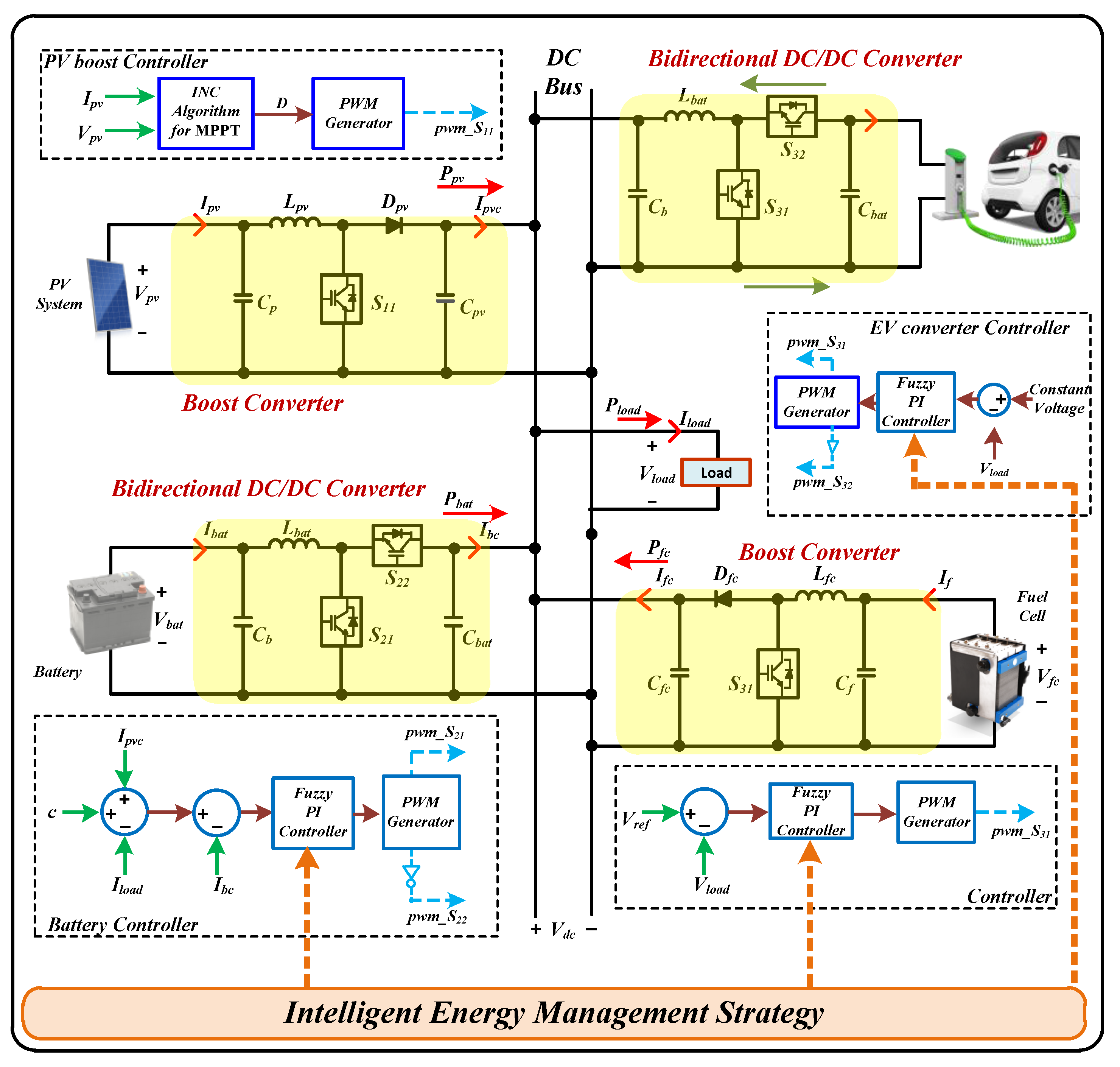
3. System Architecture
4. Control Strategy
Proposed Intelligent Hybrid Control with Fuzzy and Sparrow Search Algorithm
- Step 1
- 2.
- Step 2
- 3.
- Step 3
- 4.
- Step 4
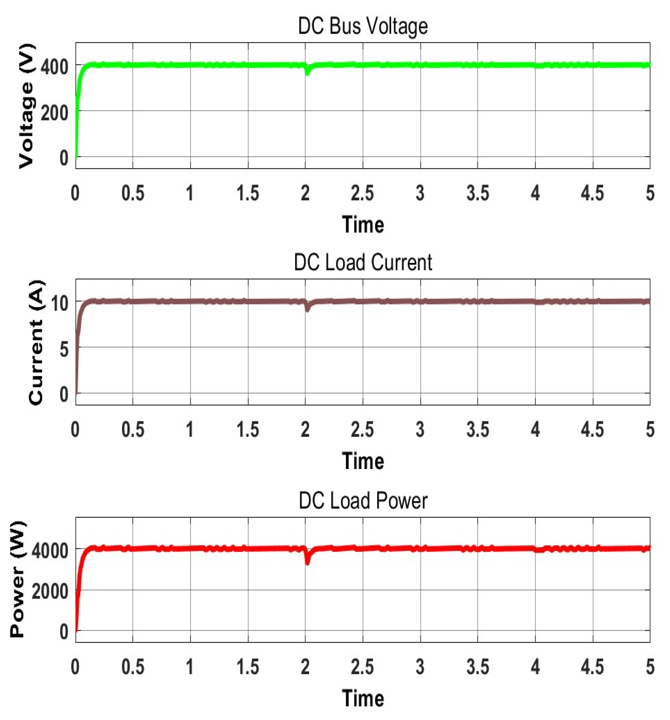
5. Results and Simulation
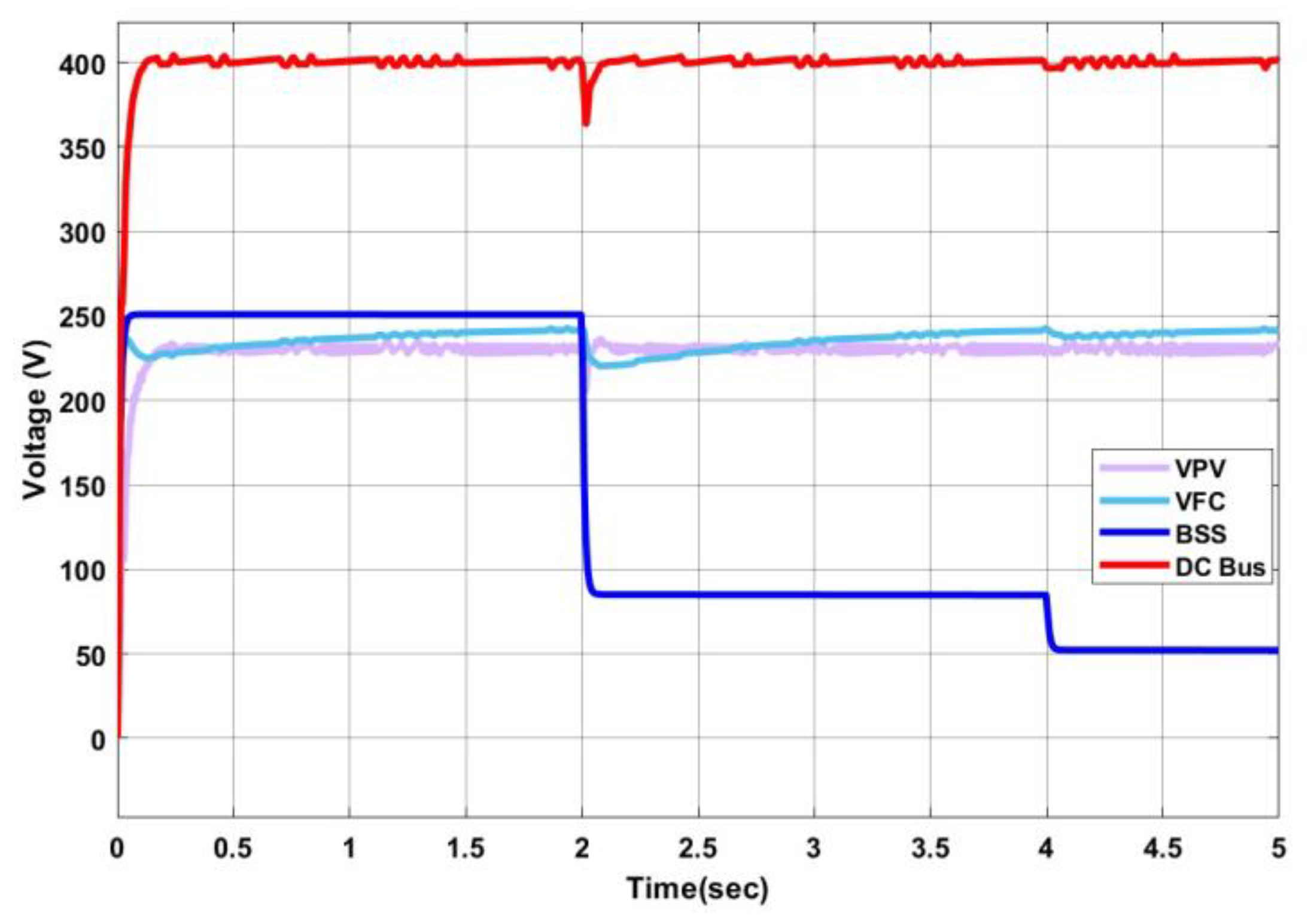
- Case (i). The effect of the system under solar PV irradiance variation is explained.
- Case (ii). Stable charging of the EV with variations in the SoC of the storage battery.
Discussion and Implications
6. Conclusions
Author Contributions
Funding
Institutional Review Board Statement
Informed Consent Statement
Data Availability Statement
Conflicts of Interest
Nomenclature
| e | Dimension of the problem |
| n | Number of sparrows |
| T | Travel direction of sparrows in range [−1,1] |
| SF | Safety threshold |
| M | Dimension of the matrix in 1 × e |
| Pij(t) | Position of the ith sparrow in jth position. |
| A2 | Alarm range [0,1] |
| V | Random value in normal distribution |
| a | Random value range [0,1] |
| E | Matrix of 1 × e with random elements |
| qi | Sparrow fitness value |
| qg | Best fitness value |
References
- Lee, C.T.; Hashim, H.; Ho, C.S.; Van Fan, Y.; Klemeš, J.J. Sustaining the Low-Carbon Emission Development in Asia and beyond: Sustainable Energy, Water, Transportation and Low-Carbon Emission Technology. J. Clean. Prod. 2017, 146, 1–13. [Google Scholar] [CrossRef]
- Wen, H.; Shi, J.; Lu, P. Can Green Technology Innovation Reduce the Operational Risks of Energy-Intensive Enterprises? Systems 2023, 11, 194. [Google Scholar] [CrossRef]
- Borenstein, S. The Private and Public Economics of Renewable Electricity Generation. J. Econ. Perspect. 2012, 26, 67–92. [Google Scholar] [CrossRef]
- Onat, N.C.; Kucukvar, M. A Systematic Review on Sustainability Assessment of Electric Vehicles: Knowledge Gaps and Future Perspectives. Environ. Impact Assess. Rev. 2022, 97, 106867. [Google Scholar] [CrossRef]
- Tan, K.M.; Babu, T.S.; Ramachandaramurthy, V.K.; Kasinathan, P.; Solanki, S.G.; Raveendran, S.K. Empowering Smart Grid: A Comprehensive Review of Energy Storage Technology and Application with Renewable Energy Integration. J. Energy Storage 2021, 39, 102591. [Google Scholar] [CrossRef]
- He, J.J.; Van Bossuyt, D.L.; Pollman, A. Experimental Validation of Systems Engineering Resilience Models for Islanded Microgrids. Systems 2022, 10, 245. [Google Scholar] [CrossRef]
- Sedaghati, R.; Shakarami, M.R. A novel control strategy and power management of hybrid PV/FC/SC/battery renewable power system-based grid-connected microgrid. Sustain. Cities Soc. 2019, 44, 830–843. [Google Scholar] [CrossRef]
- Peterson, C.J.; Van Bossuyt, D.L.; Giachetti, R.E.; Oriti, G. Analyzing Mission Impact of Military Installations Microgrid for Resilience. Systems 2021, 9, 69. [Google Scholar] [CrossRef]
- Akter, H.; Howlader, H.O.R.; Nakadomari, A.; Islam, M.R.; Saber, A.Y.; Senjyu, T. A Short Assessment of Renewable Energy for Optimal Sizing of 100% Renewable Energy Based Microgrids in Remote Islands of Developing Countries: A Case Study in Bangladesh. Energies 2022, 15, 1084. [Google Scholar] [CrossRef]
- Melath, G.; Rangarajan, S.; Agarwal, V. Comprehensive Power Management Scheme for the Intelligent Operation of Photovoltaic-battery Based Hybrid Microgrid System. IET Renew. Power Gener. 2020, 14, 1688–1698. [Google Scholar] [CrossRef]
- Dash, S.K.; Garg, P.; Mishra, S.; Chakraborty, S.; Elangovan, D. Investigation of Adaptive Intelligent MPPT Algorithm for a Low-Cost IoT Enabled Standalone PV System. Aust. J. Electr. Electron. Eng. 2022, 19, 261–269. [Google Scholar] [CrossRef]
- Kotra, S.; Mishra, M.K. Design and Stability Analysis of DC Microgrid with Hybrid Energy Storage System. IEEE Trans. Sustain. Energy 2019, 10, 1603–1612. [Google Scholar] [CrossRef]
- Senapati, M.K.; Pradhan, C.; Samantaray, S.R.; Nayak, P.K. Improved Power Management Control Strategy for Renewable Energy-based DC Microgrid with Energy Storage Integration. IET Gener. Transm. Distrib. 2019, 13, 838–849. [Google Scholar] [CrossRef]
- Ibrahim, A.Q.; Attar, H.; Amer, A.; Deif, M.A.; Solyman, A.A.A. Development of a Hybrid Support Vector Machine with Grey Wolf Optimization Algorithm for Detection of the Solar Power Plants Anomalies. Systems 2023, 11, 237. [Google Scholar] [CrossRef]
- Pradhan, C.; Senapati, M.K.; Malla, S.G.; Nayak, P.K.; Gjengedal, T. Coordinated Power Management and Control of Standalone PV-Hybrid System with Modified IWO-Based MPPT. IEEE Syst. J. 2021, 15, 3585–3596. [Google Scholar] [CrossRef]
- Gao, K.; Wang, T.; Han, C.; Xie, J.; Ma, Y.; Peng, R. A Review of Optimization of Microgrid Operation. Energies 2021, 14, 2842. [Google Scholar] [CrossRef]
- Freitas, D.; Lopes, L.G.; Morgado-Dias, F. Particle Swarm Optimisation: A Historical Review up to the Current Developments. Entropy 2020, 22, 362. [Google Scholar] [CrossRef]
- Xue, J.; Shen, B. A novel swarm intelligence optimization approach: Sparrow search algorithm. Syst. Sci. Control Eng. 2020, 8, 22–34. [Google Scholar] [CrossRef]
- Wu, C.; Fu, X.; Pei, J.; Dong, Z. A Novel Sparrow Search Algorithm for the Traveling Salesman Problem. IEEE Access 2021, 9, 153456–153471. [Google Scholar] [CrossRef]
- Bharatee, A.; K. Ray, P.; Ghosh, A. A Power Management Scheme for Grid-Connected PV Integrated with Hybrid Energy Storage System. J. Mod. Power Syst. Clean Energy 2022, 10, 954–963. [Google Scholar] [CrossRef]
- Sathyan, S.; Suryawanshi, H.M.; Ballal, M.S.; Shitole, A.B. Soft-switching DC-dC converter for distributed energy sources with high step-up voltage capability. IEEE Trans. Ind. Electron. 2015, 62, 7039–7050. [Google Scholar] [CrossRef]
- Mohan, H.M.; Dash, S.K.; Ram, S.K.; Caesarendra, W. Performance Assessment of Three-Phase PV Tied NPC Multilevel Inverter Based UPQC. In Proceedings of the 2022 International Conference on Intelligent Controller and Computing for Smart Power (ICICCSP), IEEE, Hyderabad, India, 21–23 July 2022; pp. 1–5. [Google Scholar]
- Kong, P.; Karagiannidis, G.K. Charging schemes for plug-in hybrid electric vehicles in smart grid: A survey. IEEE Access 2016, 4, 6846–6875. [Google Scholar] [CrossRef]
- Bhatti, A.R.; Salam, Z.; Ashique, H. Electric vehicle charging using photovoltaic based microgrid for remote islands. Energy Procedia 2016, 103, 213–218. [Google Scholar] [CrossRef]
- Sbordone, D.; Bertini, I.; Di Pietra, B.; Falvo, M.C.; Genovese, A.; Martirano, L. EV fast charging stations and energy storage technologies: A real implementation in the smart micro grid paradigm. Electr. Power Syst. Res. 2015, 120, 96–108. [Google Scholar] [CrossRef]
- Nagarajan, A.; Shireen, W. Grid connected residential photovoltaic energy systems with Plug-In Hybrid electric Vehicles (PHEV) as energy storage. In Proceedings of the IEEE PES General Meeting, Providence, RI, USA, 25–29 July 2010; pp. 1–5. [Google Scholar]
- Shengjun, W.; Qingshan, X.; Qun, L.; Xiaodong, Y.; Bing, C. Optimal EV Charging Control Strategy Based on DC Microgrid. Energy Procedia 2016, 100, 243–247. [Google Scholar] [CrossRef]
- Sangswang, A.; Konghirun, M. Optimal Strategies in Home Energy Management System Integrating Solar Power, Energy Storage, and Vehicle-to-Grid for Grid Support and Energy Efficiency. IEEE Trans. Ind. Appl. 2020, 56, 5716–5728. [Google Scholar] [CrossRef]
- Sánchez-Sáinz, H.; García-Vázquez, C.-A.; Llorens Iborra, F.; Fernández-Ramírez, L.M. Methodology for the Optimal Design of a Hybrid Charging Station of Electric and Fuel Cell Vehicles Supplied by Renewable Energies and an Energy Storage System. Sustainability 2019, 11, 5743. [Google Scholar] [CrossRef]
- Wang, D.; Locment, F.; Sechilariu, M. Modelling, Simulation, and Management Strategy of an Electric Vehicle Charging Station Based on a DC Microgrid. Appl. Sci. 2020, 10, 2053. [Google Scholar] [CrossRef]
- Atawi, I.E.; Hendawi, E.; Zaid, S.A. Analysis and Design of a Standalone Electric Vehicle Charging Station Supplied by Photovoltaic Energy. Processes 2021, 9, 1246. [Google Scholar] [CrossRef]
- Kharrich, M.; Kamel, S.; Ellaia, R.; Akherraz, M.; Alghamdi, A.S.; Abdel-Akher, M.; Eid, A.; Mosaad, M.I. Economic and Ecological Design of Hybrid Renewable Energy Systems Based on a Developed IWO/BSA Algorithm. Electronics 2021, 10, 687. [Google Scholar] [CrossRef]
- Mathewos, H.; Khan, B. Development of DC Microgrid Integrated Electric Vehicle Charging Station with Fuzzy Logic Controller. Front. Energy Res. 2022, 10, 678. [Google Scholar] [CrossRef]
- García, P.; Torreglosa, J.P.; Fernández, L.M.; Jurado, F. Improving Long-Term Operation of Power Sources in Off-Grid Hybrid Systems Based on Renewable Energy, Hydrogen and Battery. J. Power Sources 2014, 265, 149–159. [Google Scholar] [CrossRef]
- Mohan, H.M.; Dash, S.K. Optimized Power Flow Management Based on Harris Hawks Optimization for an Islanded DC Microgrid. Energy Harvest. Syst. 2023. [Google Scholar] [CrossRef]
- Sayed, K.; Abo-Khalil, A.G.; Alghamdi, A.S. Optimum Resilient Operation and Control DC Microgrid Based Electric Vehicles Charging Station Powered by Renewable Energy Sources. Energies 2019, 12, 4240. [Google Scholar] [CrossRef]
- Hou, G.; Qin, L.; Zheng, X.; Zhang, J. Application of PSO-Based Fuzzy PI Controller in Multi-Area AGC System after Deregulation. In Proceedings of the 2012 7th IEEE Conference on Industrial Electronics and Applications (ICIEA), IEEE, Singapore, 18–20 July 2012; pp. 1417–1422. [Google Scholar]
- Guo, L.; Abdul, N.M.M. Design and Evaluation of Fuzzy Adaptive Particle Swarm Optimization Based Maximum Power Point Tracking on Photovoltaic System under Partial Shading Conditions. Front. Energy Res. 2021, 9. [Google Scholar] [CrossRef]
- Fathy, A.; Alanazi, T.M.; Rezk, H.; Yousri, D. Optimal Energy Management of Micro-Grid Using Sparrow Search Algorithm. Energy Rep. 2022, 8, 758–773. [Google Scholar] [CrossRef]
- Singh, P.; Lather, J.S. Power Management and Control of a Grid-Independent DC Microgrid with Hybrid Energy Storage System. Sustain. Energy Technol. Assess. 2021, 43, 100924. [Google Scholar] [CrossRef]
- Bharatee, A.; Ray, P.K.; Ghosh, A. Hardware Design for Implementation of Energy Management in a Solar-Interfaced DC Microgrid. IEEE Trans. Consum. Electron. 2023, 1. [Google Scholar] [CrossRef]
- Patel, S.; Ghosh, A.; Ray, P.K. Optimum Control of Power Flow Management in PV, Wind, and Battery-Integrated Hybrid Microgrid Systems by Implementing in Real-Time Digital Simulator-Based Platform. Soft Comput. 2023. [Google Scholar] [CrossRef]
- Singh, O.; Gupta, S.K. A Review on Recent Mppt Techniques for Photovoltaic System. In Proceedings of the 2018 IEEMA Engineer Infinite Conference (eTechNxT), IEEE, New Delhi, India, 13–14 March 2018; pp. 1–6. [Google Scholar]
- Zahraoui, Y.; Alhamrouni, I.; Mekhilef, S.; Basir Khan, M.R.; Seyedmahmoudian, M.; Stojcevski, A.; Horan, B. Energy Management System in Microgrids: A Comprehensive Review. Sustainability 2021, 13, 10492. [Google Scholar] [CrossRef]
- Sun, L.; Wu, G.; Xue, Y.; Shen, J.; Li, D.; Lee, K.Y. Coordinated Control Strategies for Fuel Cell Power Plant in a Microgrid. IEEE Trans. Energy Convers. 2018, 33, 1–9. [Google Scholar] [CrossRef]
- Dash, S.K.; Chakraborty, S.; Roccotelli, M.; Sahu, U.K. Hydrogen Fuel for Future Mobility: Challenges and Future Aspects. Sustainability 2022, 14, 8285. [Google Scholar] [CrossRef]
- Mishra, S.; Rajashekaran, S.; Mohan, P.K.; Lokesh, S.M.; Ganiga, H.J.; Dash, S.K.; Roccotelli, M. Implementation of an ADALINE-Based Adaptive Control Strategy for an LCLC-PV-DSTATCOM in Distribution System for Power Quality Improvement. Energies 2022, 16, 323. [Google Scholar] [CrossRef]
- Elrayyah, A.; Sozer, Y.; Elbuluk, M.E. Modeling and Control Design of Microgrid-Connected PV-Based Sources. IEEE J. Emerg. Sel. Top. Power Electron. 2014, 2, 907–919. [Google Scholar] [CrossRef]
- Kuo, C.-L.; Lin, C.-H.; Yau, H.-T.; Chen, J.-L. Using Self-Synchronization Error Dynamics Formulation Based Controller for Maximum Photovoltaic Power Tracking in Micro-Grid Systems. IEEE J. Emerg. Sel. Top. Circuits Syst. 2013, 3, 459–467. [Google Scholar] [CrossRef]
- Shang, L.; Guo, H.; Zhu, W. An Improved Based on Incremental Conductance Algorithm. Prot. Control. Mod. Power Syst. 2020, 5, 14. [Google Scholar] [CrossRef]
- Sera, D.; Mathe, L.; Kerekes, T.; Spataru, S.V.; Teodorescu, R. On the Perturb-and-Observe and Incremental Conductance MPPT Methods for PV Systems. IEEE J. MPPT Control. Strategy Photovolt. 2013, 3, 1070–1078. [Google Scholar] [CrossRef]
- Zhang, Y.; Shotorbani, A.M.; Wang, L.; Mohammadi-Ivatloo, B. Distributed Secondary Control of a Microgrid with A Generalized PI Finite-Time Controller. IEEE Open J. Power Energy 2021, 8, 57–67. [Google Scholar] [CrossRef]
- Murdianto, F.D.; Nansur, A.R.; Hermawan, A.S.L.; Purwanto, E.; Jaya, A.; Rifadil, M.M. Modeling and Simulation of MPPT SEPIC—BUCK Converter Series Using Flower Pollination Algorithm (FPA)—PI Controller in DC Microgrid Isolated System. In Proceedings of the 2018 International Electrical Engineering Congress (iEECON), IEEE, Krabi, Thailand, 7–9 March 2018; pp. 1–4. [Google Scholar]
- Seidi Khorramabadi, S.; Bakhshai, A. Critic-Based Self-Tuning PI Structure for Active and Reactive Power Control of VSCs in Microgrid Systems. IEEE Trans. Smart Grid 2015, 6, 92–103. [Google Scholar] [CrossRef]
- Barhoumi, E.M.; Farhani, S.; Bacha, F. High Efficiency Power Electronic Converter for Fuel Cell System Application. Ain Shams Eng. J. 2021, 12, 2655–2664. [Google Scholar] [CrossRef]
- Rai, N.; Rai, B. Control of Fuzzy Logic Based PV-Battery Hybrid System for Standalone DC Applications. J. Electr. Syst. Inf. Technol. 2018, 5, 135–143. [Google Scholar] [CrossRef]
- Reddy, B.M.; Samuel, P. A Comparative Analysis of Non-Isolated Bi-Directional Dc-Dc Converters. In Proceedings of the 2016 IEEE 1st International Conference on Power Electronics, Intelligent Control and Energy Systems (ICPEICES), IEEE, Delhi, India, 4–6 July 2016; pp. 1–6. [Google Scholar]
- Yuan, J.; Zhao, Z.; Liu, Y.; He, B.; Wang, L.; Xie, B.; Gao, Y. DMPPT Control of Photovoltaic Microgrid Based on Improved Sparrow Search Algorithm. IEEE Access 2021, 9, 16623–16629. [Google Scholar] [CrossRef]
- Hannan, M.A.; Ali, J.A.; Hossain Lipu, M.S.; Mohamed, A.; Ker, P.J.; Indra Mahlia, T.M.; Mansor, M.; Hussain, A.; Muttaqi, K.M.; Dong, Z.Y. Role of Optimization Algorithms Based Fuzzy Controller in Achieving Induction Motor Performance Enhancement. Nat. Commun. 2020, 11, 3792. [Google Scholar] [CrossRef] [PubMed]
- Ouyang, C.; Zhu, D.; Wang, F. A Learning Sparrow Search Algorithm. Comput. Intell. Neurosci. 2021, 2021, 3946958. [Google Scholar] [CrossRef] [PubMed]
- Yan, S.; Yang, P.; Zhu, D.; Zheng, W.; Wu, F. Improved Sparrow Search Algorithm Based on Iterative Local Search. Comput. Intell. Neurosci. 2021, 2021, 6860503. [Google Scholar] [CrossRef] [PubMed]
- Liu, J.; Wang, Z. A Hybrid Sparrow Search Algorithm Based on Constructing Similarity. IEEE Access Pract. Innov. Open Solut. 2021, 9, 117581–117595. [Google Scholar] [CrossRef]


| Error | Change in Error | ||||||
|---|---|---|---|---|---|---|---|
| EL | EM | ES | Z | OS | OM | OL | |
| Z | OL | OM | OS | OS | ZO | OS | ZO |
| O1 | OS | OS | OM | OS | LN | EM | EM |
| O2 | OL | OM | OM | OM | ZO | ES | ES |
| O3 | LN | EM | ES | ZO | ES | OM | OL |
| O4 | OM | OS | OS | ZO | OS | OS | OS |
| O5 | OS | OS | OM | OM | ZO | ES | LN |
| O6 | ZO | OS | OM | ZO | ES | EM | LN |
| Component | Parameters | Value |
|---|---|---|
| Fuel Cell | Number of Cells | 65 |
| Nominal Stack Efficiency | 55% | |
| Operating Temperature | 65 Celsius | |
| Nominal Air Flow Rate | 300 Ipm | |
| Nominal Supply Pressure | 1.5 bar | |
| Nominal Composition (H2, O2, H2O) | (99, 21, 1) | |
| Fuel Cell Resistance | 2.3677 ohms | |
| Nerst Voltage of one Cell | 1.2101 V | |
| Stack Power (Maximal) | 7000 W | |
| Solar PV | Temperature | 25 °C |
| Irradiance | 1000 | |
| Series Connected Modules Per | 8 | |
| Power | 2000 W | |
| Parallel Strings | 1 | |
| Open Circuit Voltage | 37.3 V | |
| Short Circuit Current | 8.15 V | |
| Number of Cells | 60 | |
| Solar PV Boost Converter | Input Resistance Inductor | 12 |
| Input Capacitor | 0.48 µF | |
| Input Inductance | 1.2 mH | |
| Fuel Cell Boost Converter | Input Resistance | 2.36 Ω |
| Input Capacitor | 0.13 µF | |
| Output Capacitor | 0.16 µF | |
| Input Inductance | 3.6 mH | |
| Bidirectional Converter | Inductance | 1.4 µF |
| Input Capacitor | 1.16 mH | |
| Li-ion battery | Capacity | 48 Ah |
| Terminal Voltage | 250 V |
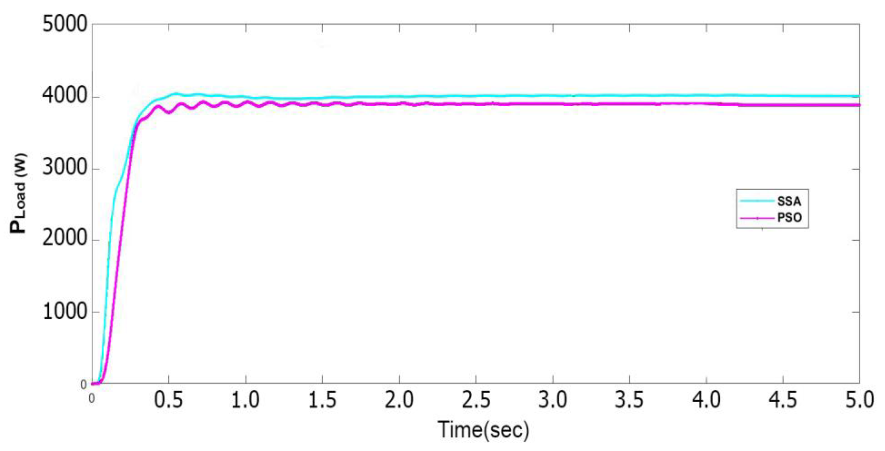
| Optimization Technique | Time Period | Power (W) |
|---|---|---|
| Hybrid SSA | 0.4 | 3900 |
| 0.5 | 3980 | |
| PSO | 0.4 | 3800 |
| 0.5 | 3900 |
Disclaimer/Publisher’s Note: The statements, opinions and data contained in all publications are solely those of the individual author(s) and contributor(s) and not of MDPI and/or the editor(s). MDPI and/or the editor(s) disclaim responsibility for any injury to people or property resulting from any ideas, methods, instructions or products referred to in the content. |
© 2023 by the authors. Licensee MDPI, Basel, Switzerland. This article is an open access article distributed under the terms and conditions of the Creative Commons Attribution (CC BY) license (https://creativecommons.org/licenses/by/4.0/).
Share and Cite
Mohan, H.M.; Dash, S.K. Renewable Energy-Based DC Microgrid with Hybrid Energy Management System Supporting Electric Vehicle Charging System. Systems 2023, 11, 273. https://doi.org/10.3390/systems11060273
Mohan HM, Dash SK. Renewable Energy-Based DC Microgrid with Hybrid Energy Management System Supporting Electric Vehicle Charging System. Systems. 2023; 11(6):273. https://doi.org/10.3390/systems11060273
Chicago/Turabian StyleMohan, Harin M., and Santanu Kumar Dash. 2023. "Renewable Energy-Based DC Microgrid with Hybrid Energy Management System Supporting Electric Vehicle Charging System" Systems 11, no. 6: 273. https://doi.org/10.3390/systems11060273