
Composite Scaffolds for Bone Tissue Regeneration Based on PCL and Mg-Containing Bioactive Glasses

 , , , ,
  ,
,  and
and
Abstract
:Simple Summary
Abstract
1. Introduction
2. Materials and Methods
2.1. Preparation
2.1.1. Preparation of Glass Powders
2.1.2. Poly(ε-Caprolactone)/Bioactive Glass Composite Preparation
2.1.3. Precision Extrusion Deposition
2.2. Characterization Methods
2.2.1. Scanning Electron Microscopy (SEM) Analysis
2.2.2. Scanning Probe Analysis
2.2.3. Nanomechanical Testing
2.2.4. In Vitro Bioactivity
2.2.5. Cell Seeding onto PCL Scaffolds
2.2.6. Cell Viability Assay
2.2.7. Cytotoxic Assay
3. Results
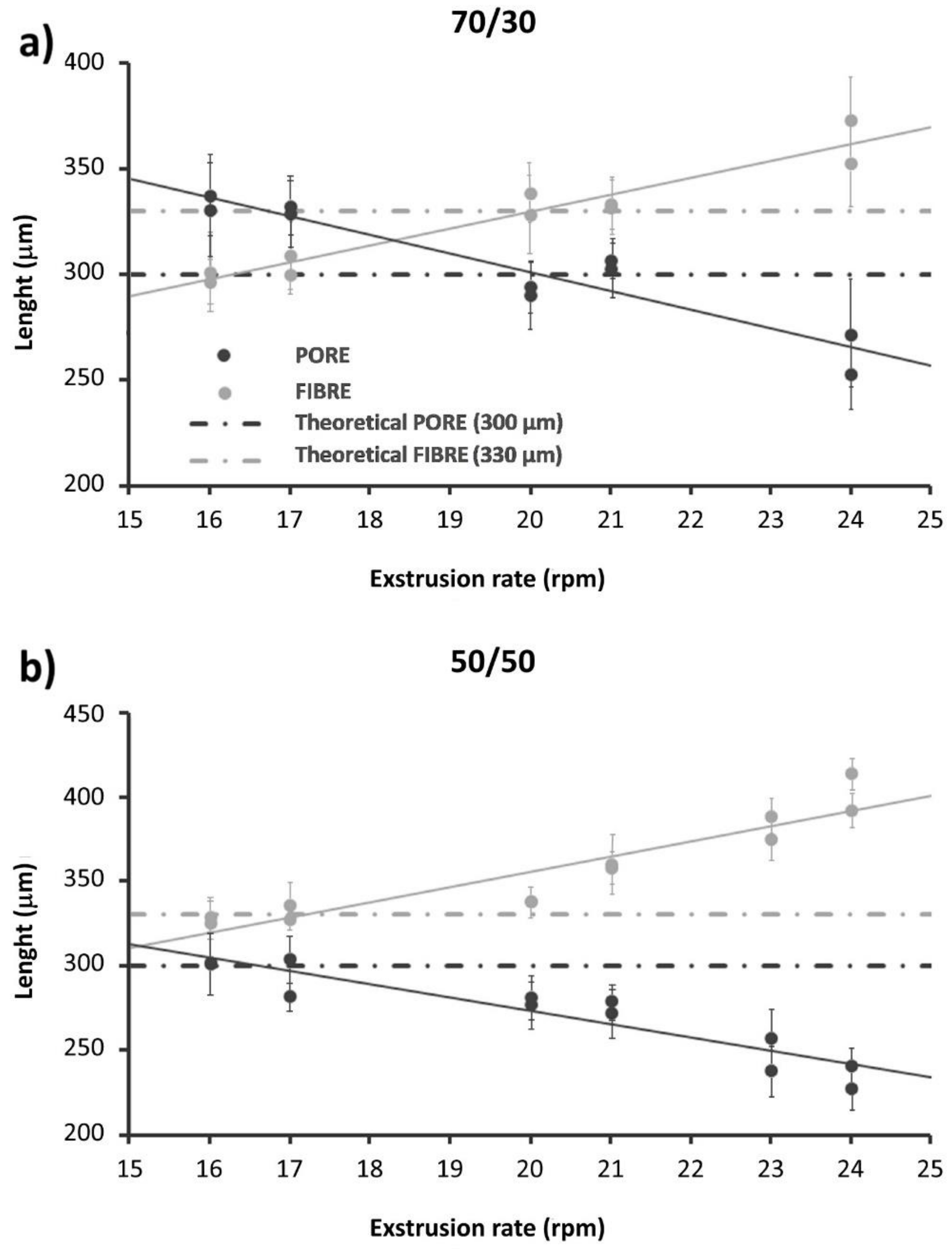
3.1. Optimization of the Scaffold Architecture
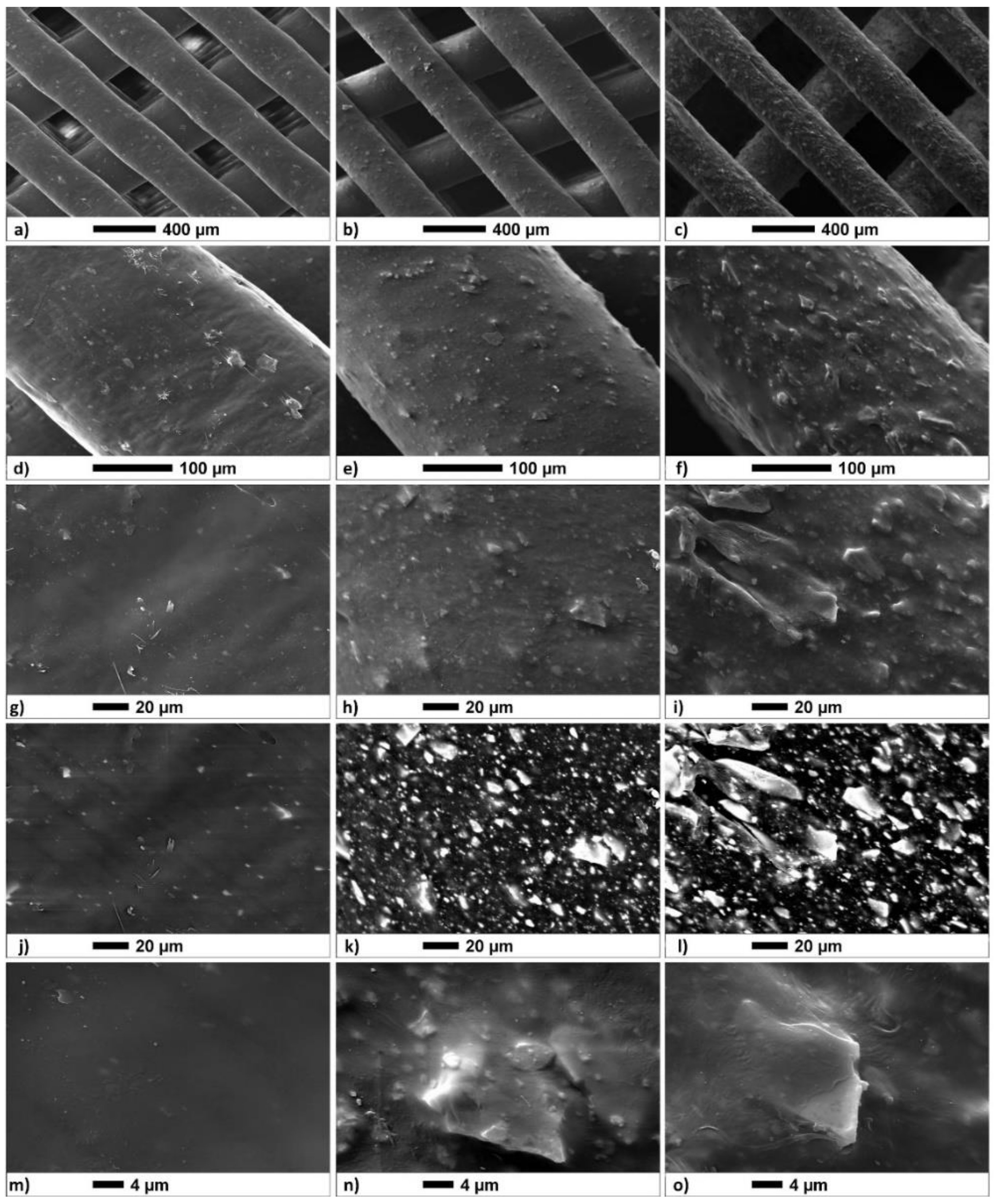
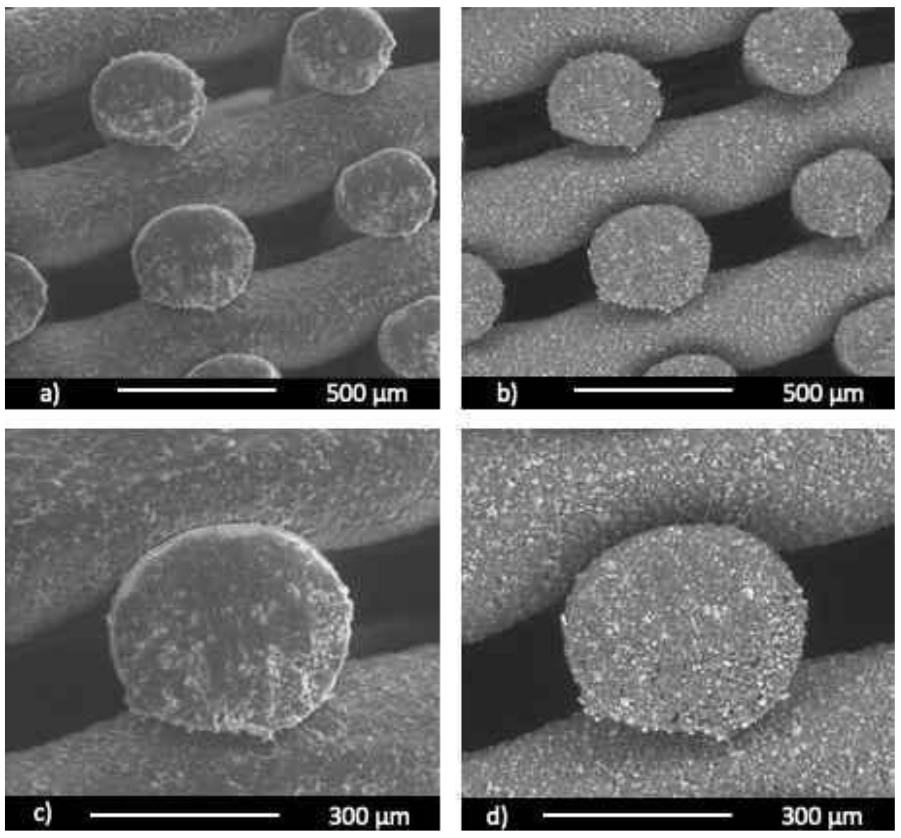
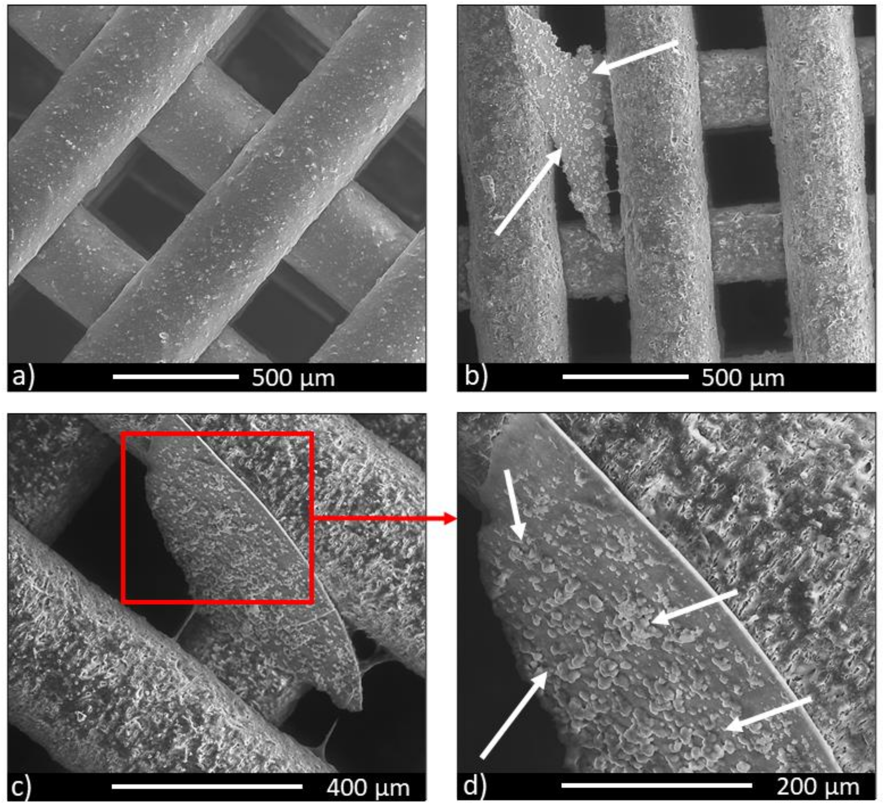
3.2. SEM Analysis
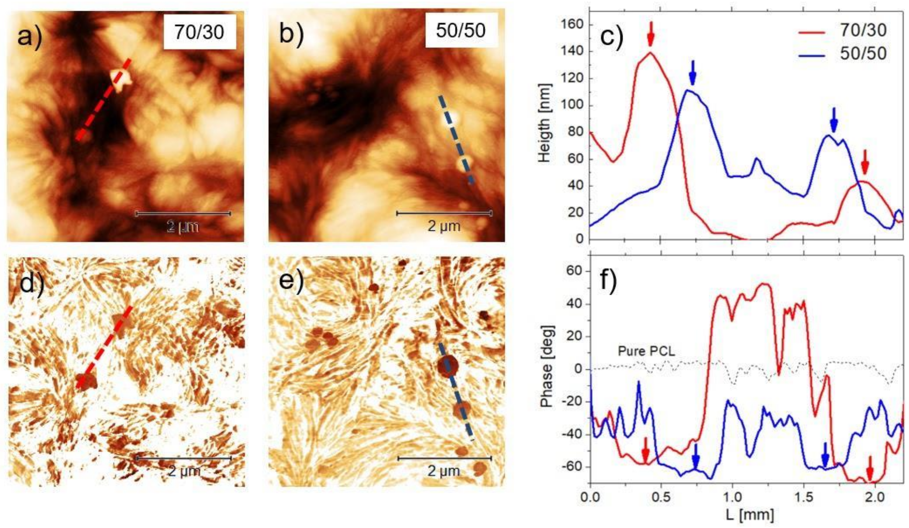
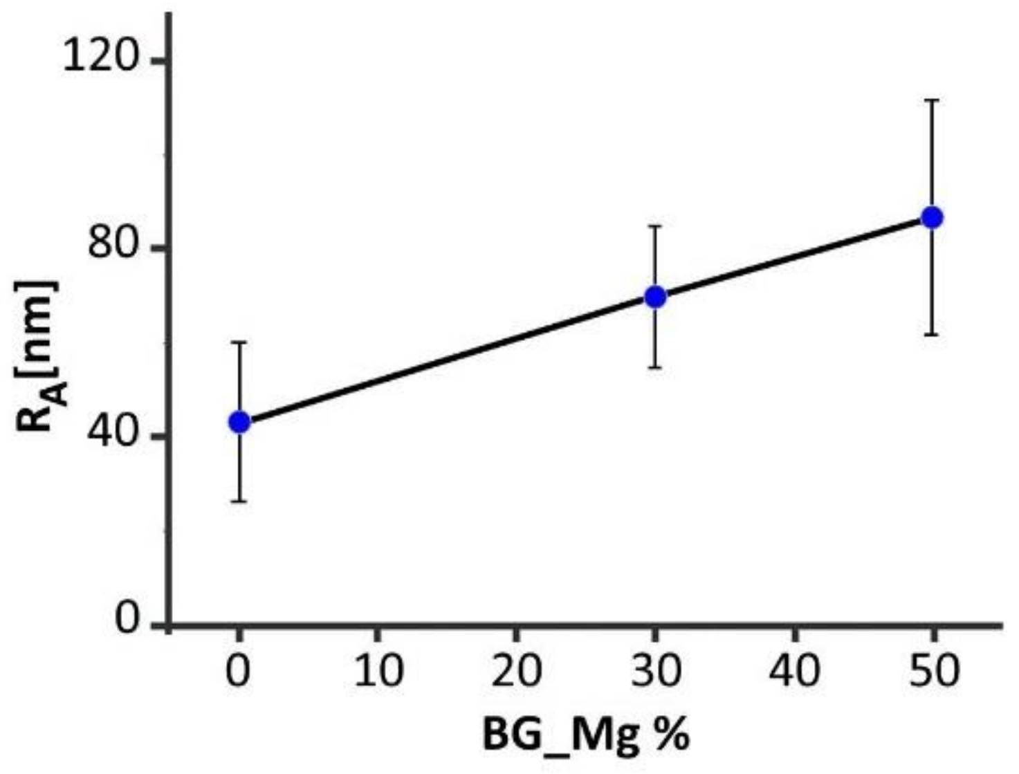
3.3. AFM
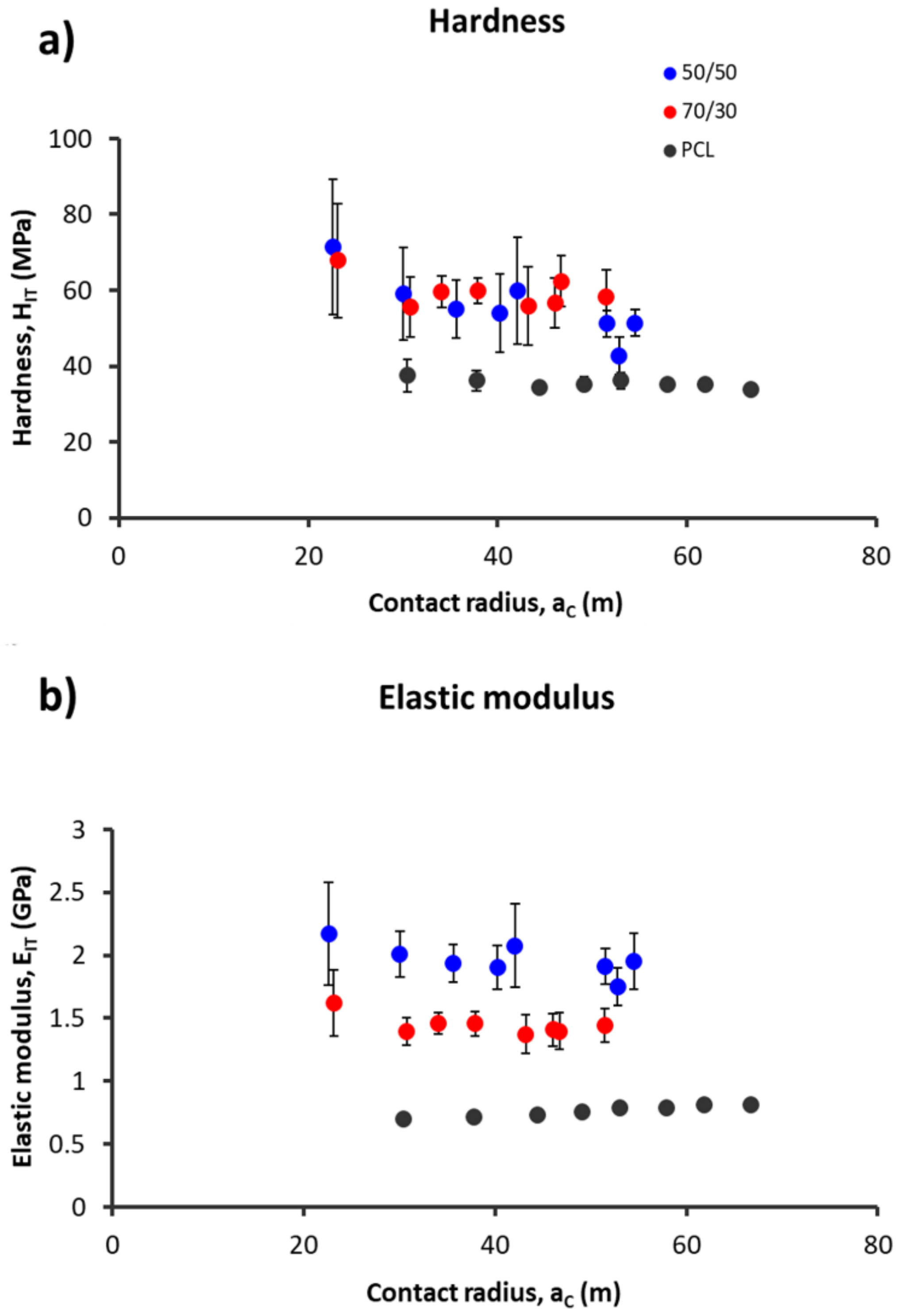
3.4. Nanomechanical Analysis
3.5. In Vitro Bioactivity
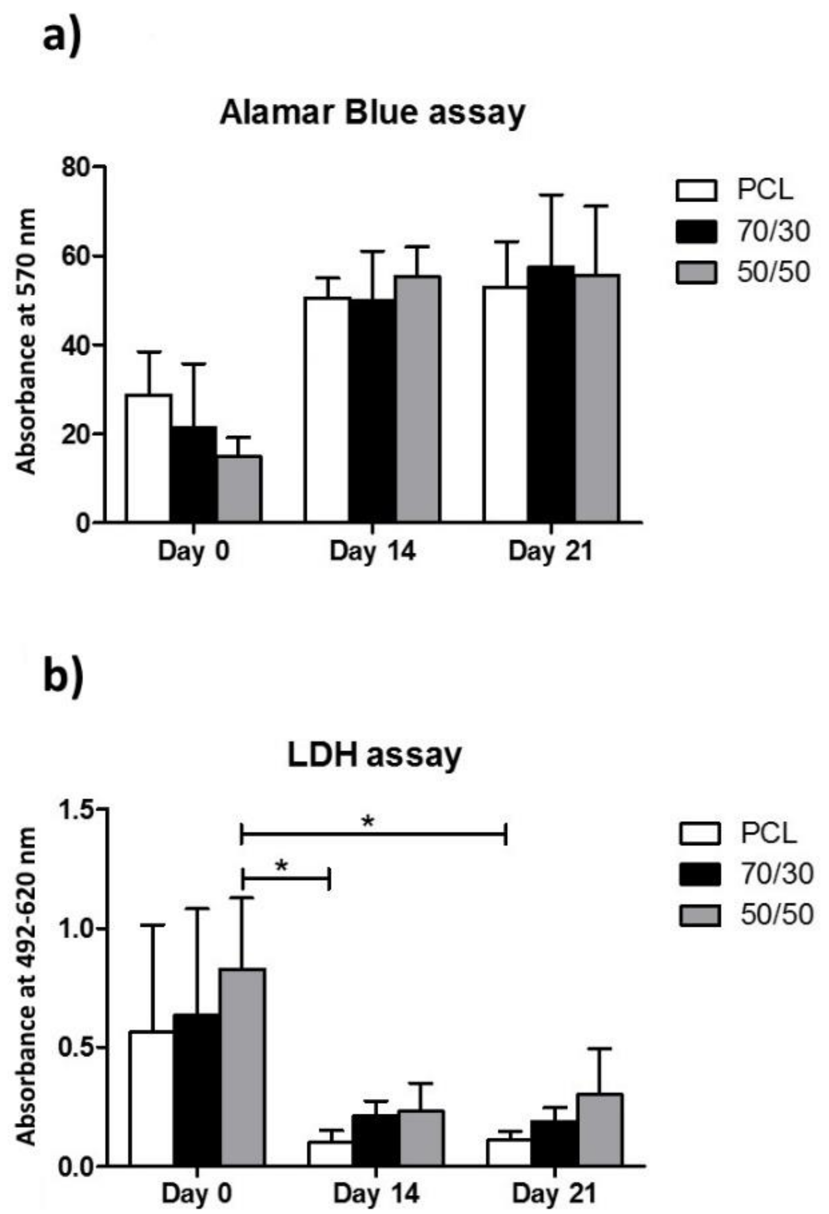
3.6. Cell Viability Assay
3.7. Cytotoxic Assay
4. Discussion
5. Conclusions
Author Contributions
Funding
Institutional Review Board Statement
Informed Consent Statement
Data Availability Statement
Acknowledgments
Conflicts of Interest
References
- Guilak, F.; Butler, D.L.; Goldstein, S.A. Functional tissue engineering: The role of biomechanics in articular cartilage repair. Clin. Orthop. Relat. Res. 2001, 391, S295–S305. [Google Scholar] [CrossRef]
- Sandino, C.; Lacroix, D. A dynamical study of the mechanical stimuli and tissue differentiation within a CaP scaffold based on micro-CT finite element models. Biomech. Model. Mechanobiol. 2010, 10, 565–576. [Google Scholar] [CrossRef]
- Caravaggi, P.; Liverani, E.; Leardini, A.; Fortunato, A.; Belvedere, C.; Baruffaldi, F.; Fini, M.; Parrilli, A.; Mattioli-Belmonte, M.; Tomesani, L.; et al. CoCr porous scaffolds manufactured via selective laser melting in orthopedics: Topographical, mechanical, and biological characterization. J. Biomed. Mater. Res. Part B Appl. Biomater. 2019, 107, 2343–2353. [Google Scholar] [CrossRef] [PubMed]
- Roseti, L.; Parisi, V.; Petretta, M.; Cavallo, C.; Desando, G.; Bartolotti, I.; Grigolo, B. Scaffolds for Bone Tissue Engineering: State of the art and new perspectives. Mater. Sci. Eng. C 2017, 78, 1246–1262. [Google Scholar] [CrossRef] [PubMed]
- Hoque, M.E.; Hutmacher, D.W.; Feng, W.; Li, S.; Huang, M.-H.; Vert, M.; Wong, Y.S. Fabrication using a rapid prototyping system and in vitro characterization of PEG-PCL-PLA scaffolds for tissue engineering. J. Biomater. Sci. Polym. Ed. 2005, 16, 1595–1610. [Google Scholar] [CrossRef] [PubMed]
- Rohner, D.; Hutmacher, D.W.; Cheng, T.K.; Oberholzer, M.; Hammer, B. In vivo efficacy of bone-marrow-coated polycapro-lactone scaffolds for the reconstruction of orbital defects in the pig. J. Biomed. Mater. Res. Part B Appl. Biomater. 2003, 66, 574–580. [Google Scholar] [CrossRef] [PubMed]
- Williams, J.M.; Adewunmi, A.; Schek, R.M.; Flanagan, C.L.; Krebsbach, P.H.; Feinberg, S.E.; Hollister, S.J.; Das, S. Bone tissue engineering using polycaprolactone scaffolds fabricated via selective laser sintering. Biomaterials 2005, 26, 4817–4827. [Google Scholar] [CrossRef] [PubMed]
- Hollister, S.J. Porous scaffold design for tissue engineering. Nat. Mater. 2005, 4, 518–524. [Google Scholar] [CrossRef] [PubMed]
- Pitt, G.G.; Gratzl, M.M.; Kimmel, G.L.; Surles, J.; Sohindler, A. Aliphatic polyesters II. The degradation of poly (DL-lactide), poly (ε-caprolactone), and their copolymers in vivo. Biomaterials 1981, 2, 215–220. [Google Scholar] [CrossRef]
- Lam, C.X.F.; Hutmacher, D.W.; Schantz, J.-T.; Woodruff, M.A.; Teoh, S.H. Evaluation of polycaprolactone scaffold degradation for 6 months in vitro and in vivo. J. Biomed. Mater. Res. Part A 2009, 90, 906–919. [Google Scholar] [CrossRef]
- Brunelli, M.; Perrault, C.; Lacroix, D. Mechanical response of 3D Insert® PCL to compression. J. Mech. Behav. Biomed. Mater. 2017, 65, 478–489. [Google Scholar] [CrossRef] [Green Version]
- Wutticharoenmongkol, P.; Pavasant, P.; Supaphol, P. Osteoblastic Phenotype Expression of MC3T3-E1 Cultured on Electro-spun Polycaprolactone Fiber Mats Filled with Hydroxyapatite Nanoparticles. Biomacromolecules 2007, 8, 2602–2610. [Google Scholar] [CrossRef]
- Hristov, V.; Radev, L.; Samuneva, B.; Apostolov, G. Organic/inorganic bioactive materials Part I: Synthesis, structure and in vitro assessment of collagen/silicocarnotite biocoatings. Open Chem. 2009, 7, 702–710. [Google Scholar] [CrossRef] [Green Version]
- Rezwan, K.; Chen, Q.Z.; Blaker, J.J.; Boccaccini, A.R. Biodegradable and bioactive porous polymer/inorganic composite scaffolds for bone tissue engineering. Biomaterials 2006, 27, 3413–3431. [Google Scholar] [CrossRef]
- Bellucci, D.; Sola, A.; Salvatori, R.; Anesi, A.; Chiarini, L.; Cannillo, V. Role of magnesium oxide and strontium oxide as mod-ifiers in silicate-based bioactive glasses: Effects on thermal behaviour, mechanical properties and in-vitro bioactivity. Mater. Sci. Eng. C 2017, 72, 566–575. [Google Scholar] [CrossRef]
- Bellucci, D.; Cannillo, V.; Ciardelli, G.; Gentile, P.; Sola, A. Potassium based bioactive glass for bone tissue engineering. Ceram. Int. 2010, 36, 2449–2453. [Google Scholar] [CrossRef]
- Watts, S.; Hill, R.; O’Donnell, M.; Law, R. Influence of magnesia on the structure and properties of bioactive glasses. J. Non-Cryst. Solids 2010, 356, 517–524. [Google Scholar] [CrossRef] [Green Version]
- Zreiqat, H.; Howlett, C.R.; Zannettino, A.; Evans, P.; Schulze-Tanzil, G.; Knabe, C.; Shakibaei, M. Mechanisms of magnesium-stimulated adhesion of osteoblastic cells to commonly used orthopaedic implants. J. Biomed. Mater. Res. 2020, 62, 175–184. [Google Scholar] [CrossRef]
- Marchiori, G.; Berni, M.; Boi, M.; Petretta, M.; Bellucci, D.; Cannillo, V.; Garavelli, C.; Bianchi, M. Design of a novel procedure for the optimization of the mechanical performances of 3D printed scaffolds for bone tissue engineering combining CAD, Taguchi method and FEA. Med. Eng. Phys. 2019, 69, 92–99. [Google Scholar] [CrossRef]
- Mallick, S.; Tripathi, S.; Srivastava, P. Advancement in Scaffolds for Bone Tissue Engineering: A Review. IOSR J. Pharm. Bio. Sci. 2015, 10, 37–54. [Google Scholar]
- Feng, P.; Wei, P.; Shuai, C.; Peng, S. Characterization of Mechanical and Biological Properties of 3-D Scaffolds Reinforced with Zinc Oxide for Bone Tissue Engineering. PLoS ONE 2014, 9, e87755. [Google Scholar] [CrossRef] [Green Version]
- Roohani-Esfahani, S.-I.; Newman, P.; Zreiqat, H. Design and Fabrication of 3D printed Scaffolds with a Mechanical Strength Comparable to Cortical Bone to Repair Large Bone Defects. Sci. Rep. 2016, 6, 19468. [Google Scholar] [CrossRef] [Green Version]
- Alksne, M.; Kalvaityte, M.; Simoliunas, E.; Rinkunaite, E.; Gendviliene, I.; Locs, I.; Rutkunas, V.; Bukelskiene, V. In vitro com-parison of 3D printed polylactic acid/hydroxyapatite and polylactic acid/bioglass composite scaffolds: Insights into materials for bone regeneration. J. Mech. Behav. Biomed. Mater. 2020, 104, 103641. [Google Scholar] [CrossRef]
- Sergi, R.; Bellucci, D.; Cannillo, V. A Review of Bioactive Glass/Natural Polymer Composites: State of the Art. Materials 2020, 13, 5560. [Google Scholar] [CrossRef]
- Distler, T.; Fournier, N.; Grünewald, A.; Polley, C.; Seitz, H.; Detsch, R.; Boccaccini, A.R. Polymer-Bioactive Glass Composite Filaments for 3D Scaffold Manufacturing by Fused Deposition Modeling: Fabrication and Characterization. Front. Bioeng. Biotechnol. 2020, 8, 552. [Google Scholar] [CrossRef]
- Doerner, M.; Nix, W. A method for interpreting the data from depth-sensing indentation instruments. J. Mater. Res. 1986, 1, 601–609. [Google Scholar] [CrossRef]
- Olesiak, S.E.; Oyen, M.L.; Ferguson, V.L. Viscous-elastic-plastic behavior of bone using Berkovich nanoindentation. Mech. Time Depend. Mater. 2010, 14, 111–124. [Google Scholar] [CrossRef]
- Martinez-Vàzquez, F.J.; Perera, F.H.; Miranda, P.; Pajares, A.; Guiberteau, F. Improving the compressive strength of bioceramic robocast scaffolds by polymer infiltration. Acta Biomater. 2010, 6, 4361–4368. [Google Scholar] [CrossRef] [PubMed]
- Campbell, S.E.; Ferguson, V.L.; Hurley, D.C. Nanomechanical mapping of the osteochondral interface with contact resonance force microscopy and nanoindentation. Acta Biomater. 2012, 8, 4389–4396. [Google Scholar] [CrossRef] [PubMed]
- Kokubo, T.; Takadama, H. How useful is SBF in predicting in vivo bone bioactivity? Biomaterials 2006, 27, 2907–2915. [Google Scholar] [CrossRef] [PubMed]
- Ye, Z.; Zhao, X. Phase imaging atomic force microscopy in the characterization of biomaterials. J. Microsc. 2010, 238, 27–35. [Google Scholar] [CrossRef]
- Xiao, X.; Liu, R.; Tang, X. Electrophoretic deposition of silicon-substituted hydroxyapatite/poly(ε-caprolactone) composite coatings. J. Mater. Sci. Mater. Electron. 2009, 20, 691–697. [Google Scholar] [CrossRef]
- Yang, F.; Wolke, J.G.C.; Jansen, J.A. Biomimetic calcium phosphate coating on electrospun poly(ε-caprolactone) scaffolds for bone tissue engineering. Chem. Eng. J. 2008, 137, 154–161. [Google Scholar] [CrossRef]
- Kim, Y.B.; Lim, J.Y.; Yang, G.H.; Seo, J.-H.; Ryu, H.-S.; Kim, G.H. 3D-printed PCL/bioglass (BGS-7) composite scaffolds with high toughness and cell-responses for bone tissue regeneration. J. Indust. Eng. Chem. 2019, 79, 163–171. [Google Scholar] [CrossRef]
- Liu, H.; Webster, T.J. Mechanical properties of dispersed ceramic nanoparticles in polymer composites for orthopedic ap-plications. Int. J. Nanomed. 2010, 5, 299–313. [Google Scholar]
- Yeung, T.; Georges, P.C.; Flanagan, L.A.; Marg, B.; Ortiz, M.; Funaki, M.; Zahir, N.; Ming, W.; Weaver, V.; Janmey, P.A. Effects of substrate stiffness on cell morphology, cytoskeletal structure, and adhesion. Cell Motil. Cytoskelet. 2004, 60, 24–34. [Google Scholar] [CrossRef]
- Khatiwala, C.B.; Peyton, S.R.; Putnam, A.J. Intrinsic mechanical properties of the extracellular matrix affect the behavior of pre-osteoblastic MC3T3-E1 cells. Am. J. Physiol. Physiol. 2006, 290, C1640–C1650. [Google Scholar] [CrossRef]
- Engler, A.J.; Sen, S.; Sweeney, H.L.; Discher, D.E. Matrix Elasticity Directs Stem Cell Lineage Specification. Cell 2006, 126, 677–689. [Google Scholar] [CrossRef] [Green Version]
- Tan, P.S.; Teoh, S.H. Effect of stiffness of polycaprolactone (PCL) membrane on cell proliferation. Mater. Sci. Eng. C 2007, 27, 304–308. [Google Scholar] [CrossRef]
- Lampin, M.; Legris, C.; Degrange, M.; Sigot-Luizard, M.F. Correlation between substratum roughness and wettability, cell adhesion, and cell migration. J. Biomed. Mater. Res. 1997, 36, 99–108. [Google Scholar] [CrossRef]
- Brunette, D. Spreading and orientation of epithelial cells on grooved substrata. Exp. Cell Res. 1986, 167, 203–217. [Google Scholar] [CrossRef]
- Wu, C.; Chen, M.; Zheng, T.; Yang, C. Effect of surface roughness on the initial response of MC3T3-E1 cells cultured on pol-ished titanium alloy. Biomed. Mater. Eng. 2015, 26, S155–S164. [Google Scholar]
- Faia-Torres, A.B.; Charnley, M.; Goren, T.; Guimond-Lischer, S.; Rottmar, M.; Maniura-Weber, K.; Spencer, N.D.; Reis, R.L.; Textor, M.; Neves, N.M. Osteogenic differentiation of human mesenchymal stem cells in the absence of osteogenic supple-ments: A surface-roughness gradient study. Acta Biomater. 2015, 28, 64–75. [Google Scholar] [CrossRef] [Green Version]
- Zareidoost, A.; Yousefpour, M.; Ghaseme, B.; Amanzadeh, A. The relationship of surface roughness and cell response of chemical surface modification of titanium. J. Mater. Sci. Mater. Med. 2012, 23, 1479–1488. [Google Scholar] [CrossRef]
- Lee, H.-H.; Yu, H.-S.; Jang, J.-H.; Kim, H.-W. Bioactivity improvement of poly (e-caprolactone) membrane with the addition of nanofibrous bioactive glass. Acta Biomater. 2008, 4, 622–629. [Google Scholar] [CrossRef]
- Poh, P.S.P.; Hutmacher, D.W.; Stevens, M.M.; Woodruff, M.A. Fabrication and in vitro characterization of bioactive glass composite scaffolds for bone regeneration. Biofabrication 2013, 5, 045005. [Google Scholar] [CrossRef] [Green Version]
- Bellucci, D.; Sola, A.; Cacciotti, I.; Bartoli, C.; Gazzarri, M.; Bianco, A.; Chiellini, F.; Cannillo, V. Mg-and/or Sr-doped tricalcium phosphate/bioactive glass composites: Synthesis, microstructure and biological responsiveness. Mater. Sci. Eng. C 2014, 42, 312–324. [Google Scholar] [CrossRef]
- Bellucci, D.; Braccini, S.; Chiellini, F.; Balasubramanian, P.; Boccaccini, A.R.; Cannillo, V. Bioactive glasses and glass-ceramics versus hydroxyapatite: Comparison of angiogenic potential and biological responsiveness. J. Biomed. Mater. Res. Part A 2019, 107, 2601–2609. [Google Scholar] [CrossRef]
- Cannillo, V.; Colmenares-Angulo, J.; Lusvarghi, L.; Pierli, F.; Sampath, S. In vitro characterisation of plasma-sprayed apa-tite/wollastonite glass-ceramic biocoatings on titanium alloys. J. Eur. Ceram. Soc. 2009, 29, 1665–1677. [Google Scholar] [CrossRef]
- Bohner, M.; Lemaitre, J. Can bioactivity be tested in vitro with SBF solution? Biomaterials 2009, 30, 2175–2179. [Google Scholar] [CrossRef] [Green Version]
- Rahaman, M.N.; Day, D.E.; Bal, B.S.; Fu, Q.; Jung, S.B.; Bonewald, L.F.; Tomsia, A.P. Bioactive glass in tissue engineering. Acta Biomater. 2011, 7, 2355–2373. [Google Scholar] [CrossRef] [PubMed] [Green Version]
- Cannillo, V.; Leonelli, C.; Boccaccini, A. Numerical models for thermal residual stresses in Al2O3 platelets/borosilicate glass matrix composites. Mater. Sci. Eng. A 2002, 323, 246–250. [Google Scholar] [CrossRef]
- Cannillo, V.; Montorsi, M.; Siligardi, C.; Sola, A.; de Portu, G.; Micele, L.; Pezzotti, G. Microscale computational simulation and experimental measurement of thermal residual stresses in glass–alumina functionally graded materials. J. Eur. Ceram. Soc. 2006, 26, 1411–1419. [Google Scholar] [CrossRef]


| Composite Material | Nozzle Diameter (µm) | Barrel Temperature (°C) | Printing Speed (rpm) | Extrusion Rate (rpm) |
|---|---|---|---|---|
| 70/30 | 330 | 105 | 1 | 20 |
| 50/50 | 330 | 115 | 1 | 17 |
| PCL | 330 | 115 | 4 | 18 |
Publisher’s Note: MDPI stays neutral with regard to jurisdictional claims in published maps and institutional affiliations. |
© 2021 by the authors. Licensee MDPI, Basel, Switzerland. This article is an open access article distributed under the terms and conditions of the Creative Commons Attribution (CC BY) license (https://creativecommons.org/licenses/by/4.0/).
Share and Cite
Petretta, M.; Gambardella, A.; Boi, M.; Berni, M.; Cavallo, C.; Marchiori, G.; Maltarello, M.C.; Bellucci, D.; Fini, M.; Baldini, N.; et al. Composite Scaffolds for Bone Tissue Regeneration Based on PCL and Mg-Containing Bioactive Glasses. Biology 2021, 10, 398. https://doi.org/10.3390/biology10050398
Petretta M, Gambardella A, Boi M, Berni M, Cavallo C, Marchiori G, Maltarello MC, Bellucci D, Fini M, Baldini N, et al. Composite Scaffolds for Bone Tissue Regeneration Based on PCL and Mg-Containing Bioactive Glasses. Biology. 2021; 10(5):398. https://doi.org/10.3390/biology10050398
Chicago/Turabian StylePetretta, Mauro, Alessandro Gambardella, Marco Boi, Matteo Berni, Carola Cavallo, Gregorio Marchiori, Maria Cristina Maltarello, Devis Bellucci, Milena Fini, Nicola Baldini, and et al. 2021. "Composite Scaffolds for Bone Tissue Regeneration Based on PCL and Mg-Containing Bioactive Glasses" Biology 10, no. 5: 398. https://doi.org/10.3390/biology10050398