Article

Mid-Infrared Ultra-Short Pulse Generation in a Gas-Filled Hollow-Core Photonic Crystal Fiber Pumped by Two-Color Pulses

by
Coralie Fourcade-Dutin
1,*,
Olivia Zurita-Miranda
1,2,
Patrick Mounaix
1 and
Damien Bigourd
1
1
Laboratoire IMS, UMR CNRS 5218, University of Bordeaux, 33400 Talence, France
2
Institut FEMTO-ST, Département d’Optique, UMR CNRS 6174, Université Bourgogne Franche-Comté, 25030 Besançon, France
*
Author to whom correspondence should be addressed.
Fibers 2021, 9(4), 21; https://doi.org/10.3390/fib9040021
Submission received: 19 February 2021 / Revised: 9 March 2021 / Accepted: 15 March 2021 / Published: 1 April 2021
(This article belongs to the Special Issue Hollow-Core Photonic Crystal Fibers)

Abstract

:
We show numerically that ultra-short pulses can be generated in the mid-infrared when a gas filled hollow-core fiber is pumped by a fundamental pulse and its second harmonic. The generation process originates from a cascaded nonlinear phenomenon starting from a spectral broadening of the two pulses followed by an induced phase-matched four wave-mixing lying in the mid-infrared combined with a dispersive wave. By selecting this mid-infrared band with a spectral filter, we demonstrate the generation of ultra-short 60 fs pulses at a 3–4 µm band and a pulse duration of 20 fs can be reached with an additional phase compensator.

1. Introduction

In recent years, there has been growing interest in mid-infrared (MIR) sources driven by demanding applications such as gas sensing [1], food inspection [2], life and molecular sciences [3] or the creation of secondary sources [4]. An excellent method for light generation in the MIR is to combine some laser properties with nonlinear photonic devices to create down-converted frequencies. For example, high-power sources can be made from several efficient nonlinear crystals, chosen for their optimal phase-matching conditions and absorption bands to achieve an optical parametric amplification effect or difference frequency generation. Alternative devices at lower power are based on other transparent materials such as in silicon-, lithium niobate- or chalcogenide-based waveguides [5,6,7] or specific nonlinear fibers with soft-glass materials [8].
In this manuscript, we propose to generate ultra-short pulses in the MIR by pumping a gas-filled hollow-core photonic crystal fiber (HC-PCF) with two different pulses to create an efficient phase-matched process. The HC-PCFs offer significant advantages to handle and convert ultra-short pulses. In particular, they offer a high damage threshold, which allows the propagation of high peak power [9]. In addition, the frequency conversion from the pump to the MIR can be engineered with the dispersion of the waveguide and the gas contribution, i.e., the phase matching can be tuned in real time by changing the gas pressure. Outstanding progress has also been achieved to reduce the loss of HC-PCFs in the MIR [10,11], for example, with a transmission loss of ~25–50 dB/km now being obtained by minimizing the interaction between the core guided mode and the silica walls of the cladding of an inhibited-coupling hollow-core fiber [10]. Recently, anti-resonant HC-PCFs have also gained interest [12] due to their properties, including a wide tunability of the spectral transmission bands from the ultra-violet (UV) to MIR [13,14,15] with low loss, high damage threshold [16] and a single mode propagation by choosing specific geometries [17]. Several impressive works on ultra-short pulse generation in the MIR with gas filled HC-PCFs have been reported, such as pulse compression [18], supercontinuum and MIR dispersive wave generation [13,19,20] and adiabatic down conversion from four wave mixing (FWM) processes in a tapered fiber [21]. In the later case, the HC-PCF is pumped by two picosecond pulses and seeded with a chirped signal to overlap with the conversion spectral band. In our approach, only two ultra-short pump pulses are injected and spectrally broadened in the HC-PCF. FWM are directly induced from the two broad-band pulses capable of generating pulses at 3 and 4 µm with a duration of 20 fs.
In this manuscript, we report ultra-fast MIR generation in a hollow-core photonic crystal fiber from two color pulses and we discuss the dynamics of the mechanism originating from the cascaded nonlinear phenomenon, including phase modulation and phase-matched four-wave mixing processes.

2. Anti-Resonant Fibers and Numerical Methods

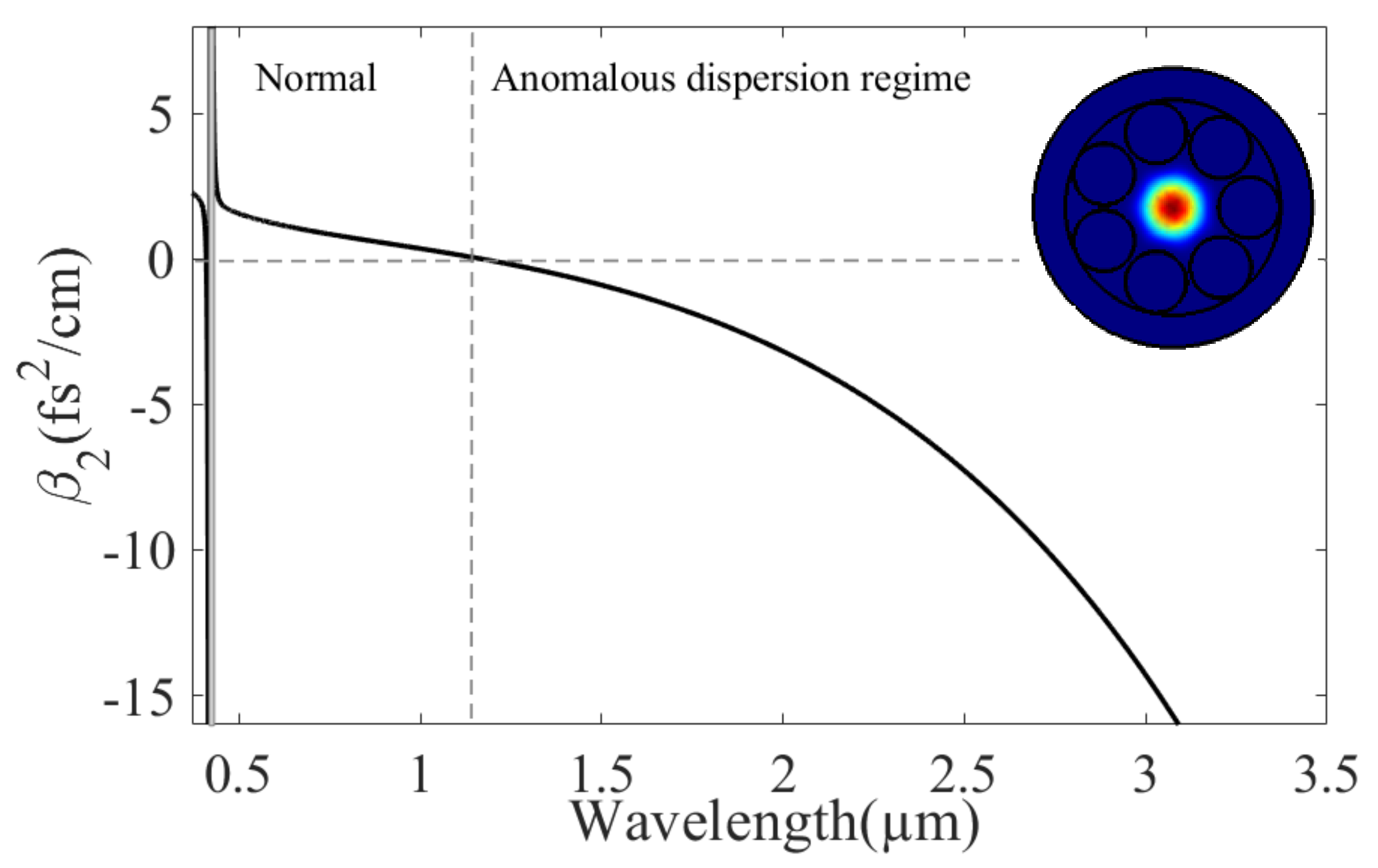
2.1. Properties of the Hollow-Core Photonic Crystal Fiber

The chosen HC-PCF geometry is a negative curvature fiber based on a single-ring structure surrounding by a hollow-core. This type of fiber generally supports a large family of high-order modes but in a specific condition (d = 0.68D with d and D the tube and core diameters, respectively), it can provide a single mode LP01 operation [17]. A schematic view is shown in the inset of Figure 1 with our chosen parameters.
The HC-PCF structure is composed of a central hollow core with D = 150 µm surrounded by seven evenly and non-touching capillaries attached to the inner surface of a thick-walled capillary. The tube diameter is set at 102 µm to ensure a robust single-mode propagation. The wall thickness t equals 0.2 µm and the gap between tube g equals 7.3 µm. The LP01 mode at 1030 nm supported by this HC-PCF has also been simulated by the finite element method (insert in Figure 1), and it also confirms the great advantage of propagating waves in the MIR with low loss since the overlap of the spatial profile with the silica structure is weak, even if the glass is highly absorbent in the MIR. For example, the power fraction of the LP01 mode at 3 µm that overlaps with the glass is less than 10−3% and the estimated transmission loss is much lower than 1 dB/m.
The group velocity dispersion, β2, is firstly analytically calculated for the fundamental mode from empirical formulae [22] derived from a modification of the Marcatelli and Schmelzer’s capillary model [23] to take into account the anti-resonant reflection. The effective index neff is first calculated as the function of the wavelength λ [22]:
n e f f = n g a s 2 u 01 λ 2 π R e f f 2 + σ 1 λ 2 λ 2 2 t n g 2 1 2
where u01 = 2.405 is the first zero of the Bessel function of the first kind, ng = 1.45 is the refractive index of silica. σ1~1.05 × 10⁻⁸ represents the strength of the resonance band. ngas is the refractive index of the gas. In Equation (1), the empirical formula for the effective radius Reff is also included from:
R e f f = f 1 D 2 1 f 2 λ 2 R t
where f1 = 1.10 and f2 = 0.05 are two dimensionless parameters obtained from [22].
From Equation (1), the propagation constant is calculated as the function and then, β2 is calculated. Figure 1 shows the dispersion curve as a function of the wavelength for an HC-PCF filled with argon at a pressure of 5 bar, including the resonance band located at ~420 nm. The second resonance band emerges at a lower wavelength and is outside the spectral domain of the FWM bands.
This pressure was chosen to obtain a zero-dispersion wavelength (ZDW) in the near infrared at 1170 nm. The effective area Aeff ~992 µm2 was also calculated from the model [22] and was assumed constant for the spectral range.

2.2. Numerical Method for the Nonlinear Pulse Propagation

The general principle for MIR generation is to pump the HC-PCF using two different ultra-short pulses, P1 and P2, with spectra centered at 1030 and 515 nm, corresponding to the emission of an ultra-fast ytterbium-doped fiber laser and a second harmonic generator. The two pulses lie in the normal dispersion regime and the spectra broaden during the propagation in the fiber. Then, the MIR light was generated from a phase-matched FWM between several created spectral components. In order to understand the concept and dynamics in great detail, we conducted numerical simulations by integrating the generalized nonlinear Schrödinger equation using the split-step Fourier method with a step size of ~5 µm
A z n 2 i n + 1 n ! β n n A T n = i γ ( 1 + i τ s h o c k T ) A 2 A
describing the evolution along the fiber length z of the complex total electric field A(z,T). In our configuration, we used 2048 points and a temporal resolution of 1.15 fs, leading to a temporal window of ~2.4 ps.
The initial field corresponds to the total field composed of P1 and P2; i.e.,
A ( z = 0 , T ) = A 1 exp ( i ( ω 1 ω c ) . T ) + A 2 exp ( i ( ω 2 ω c ) . T )
where ω1 2) and A1 (A2) are the angular frequency and the electric field amplitude of the pump P1 (P2), respectively. In our simulation, we chose to center the frequency grid between the two pumps; at ωc, corresponding to a wavelength of ~686 nm. Accordingly, we chose T in Equation (3) as the time in the frame moving at the group velocity β1c at ωc.
The complete propagation constant β is calculated in the frequency domain from the empirical model (Section 2.1) starting from the second-order expansion term; i.e., the zero- and first-order terms evaluated at ωc were removed. The time derivative in the right-hand side is important to take into account the shock term on a time scale of τ s h o c k = 1 ω c 1 n e f f ( ω ) n e f f ( ω ) ω ω c [24]. γ is the nonlinear term that allows for the generation of the new frequency components according to γ = ω c n 2 A e f f . c with the argon nonlinear index n2 equal to 4.86 × 10²³ m2/W and c, the speed of light.

3. Continuum Generation

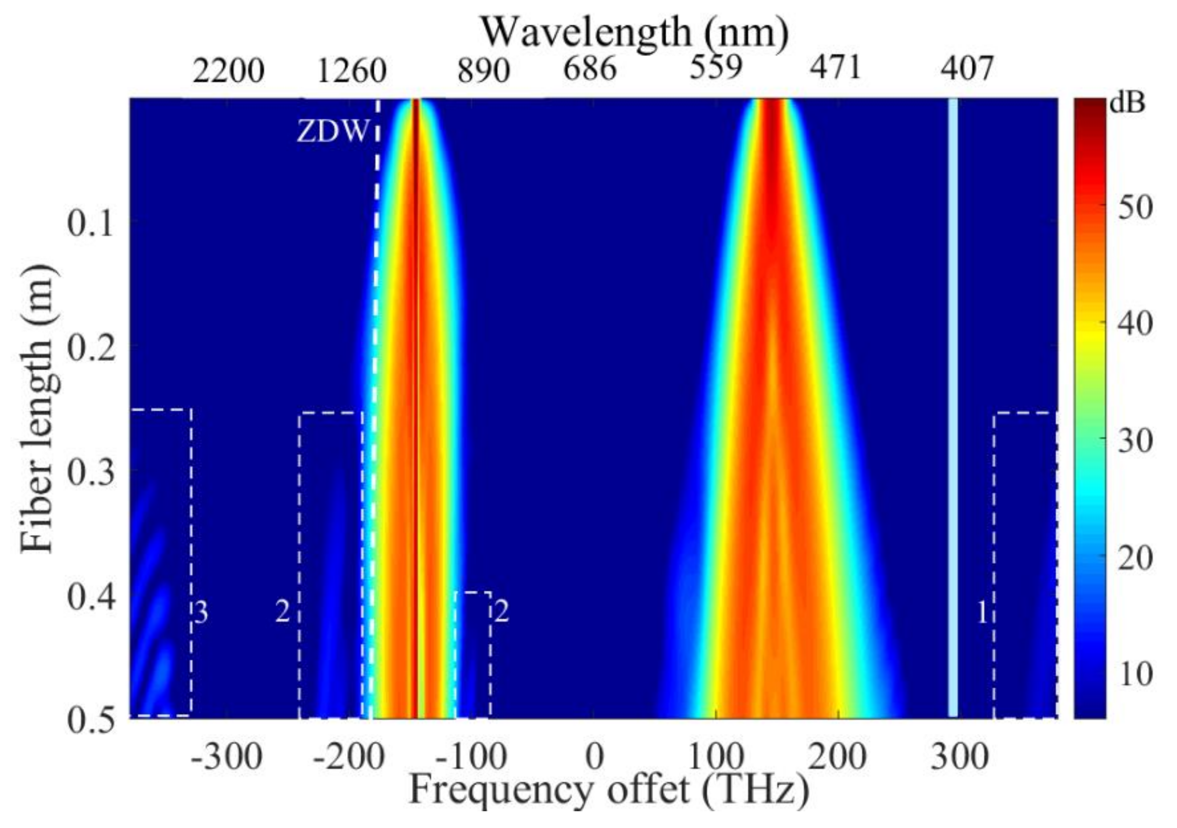
3.1. Generated Continuum from a Dual-Pump Scheme

The light is generated in the MIR from a cascade of nonlinear processes in the argon-filled HC-PCF pumped by the two pump pulses. The initial pulses P1 and P2 have a duration of 180 fs and 50 fs at Full-Width at Half Maximum (FWHM) at the Fourier transform limit. The corresponding spectral bandwidths are Δλ1~9 nm and Δλ2~8 nm at FWHM. The group delay mismatch (GDM) between the two pulses is ~176 fs/m (Figure 2a) and we consider a total fiber length of 50 cm to ensure a temporal overlap during the propagation.
At the input fiber, the energies are 12 µJ for P1 and 20 µJ for P2, and the peak powers reach 63 and 390 MW. At first, each spectrum broadens along the fiber. Figure 2b shows the spectra for a 50 cm long fiber (black solid-line). For comparison, the spectra are also displayed when only P1 (red dashed-line) or P2 (red dotted-line) is injected into the HC-PCF. Clearly, the spectral broadening of P2 is mostly due to self-phase modulation (SPM) since P1 does not significantly affect the spectral shape; i.e., the spectra are similar with or without P1. Alternatively, SPM has a negligible contribution to P1 and the phase modulation of P1 is induced by P2. This cross-phase modulation (XPM) allows for the generation of a broad-bandwidth centered at 1030 nm, even for a weaker pulse P1 [25].

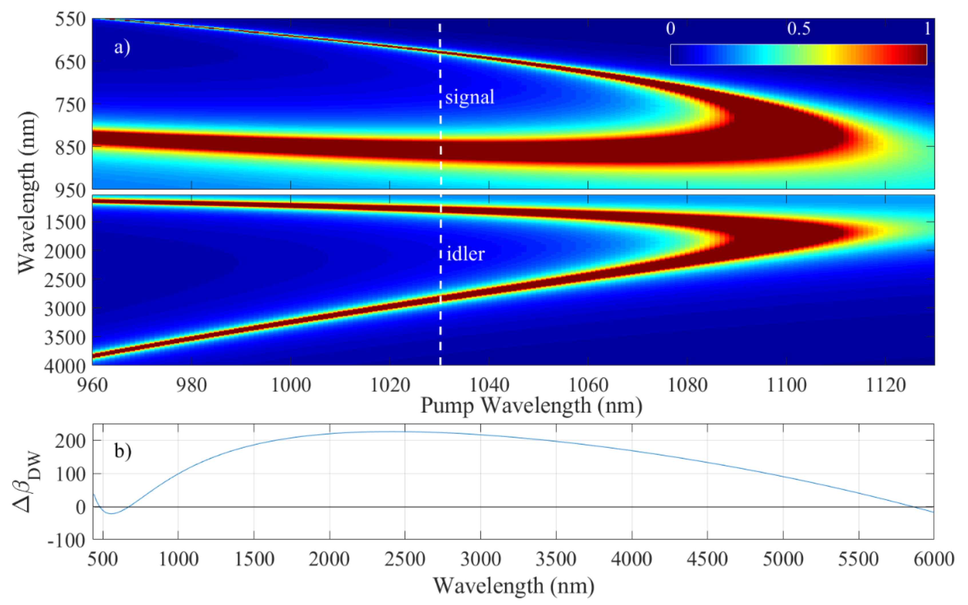
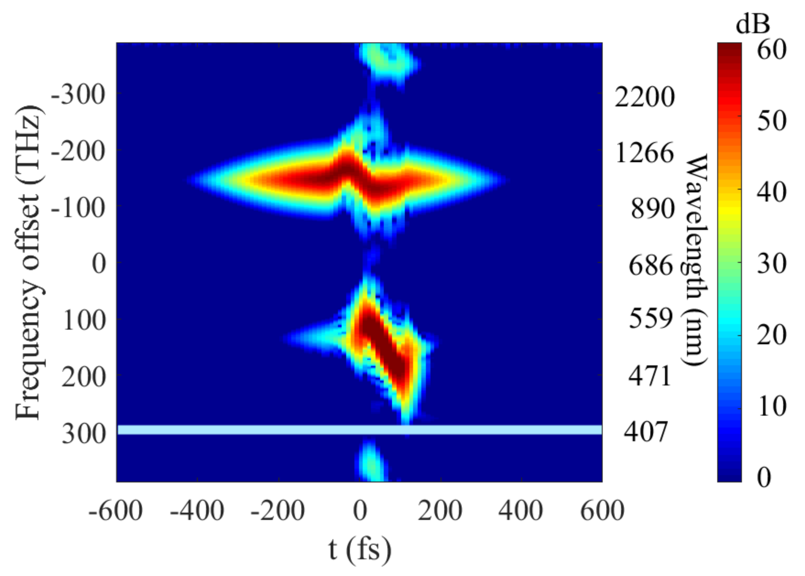
3.2. Frequency Generation Mechanism and Dynamics

Figure 3 displays the total spectrum as a function of the fiber length on a logarithmic scale. During the pulse propagation, the two pumps symmetrically undergo spectral broadening due to the phase modulations and a portion of the pump energy enters into the anomalous dispersion regime at z~10 cm. In addition, the spectral tail of the broadened pulse P2 extends and overlaps with phase-matched frequencies in which the energy transfer process takes place. Other spectral components are generated in the UV at ~374 nm (zone 1), and in the near-IR (zone 2) and MIR (zone 3) due to the interaction of the two main pulses with a large spectral bandwidth to achieve phase-match processes mostly from a FWM. For example, the radiation at (zone 1) results from the FWM process between the pump (P2) seeded with P1, leading to an angular frequency of 2ω21. The origin of the other FWM in the infrared will be detailed in the following paragraphs.
As observed in Figure 3, the MIR band is only efficiently generated when the signal at ~620 nm is created from the early spectral broadening process of P2. Firstly, the P2 spectrum broadens during propagation due to SPM and at ~30 cm, the spectral tail reaches the visible band of the FWM and MIR waves are generated. We also observed that the band at 1.2 µm arises at z~30 cm once the signal at 850 nm arises from the spectral broadening of P1.
The infrared FWMs relies on a degenerated phase-matched process involving one strong pump pulse (i.e., P1). A weak wave, at the angular frequency ωs, seeds the FWM process and originates from the broadening of either the second pulse P2 (for Zone 3) or P1 (for zone 2). One idler band is generated in the MIR at the angular frequency ωi, and then it will be selected with band-pass filters. In order to reach an ultrashort pulse, a broad-band FWM is required and we benefit from a pump pulse (P1) with a broad spectral bandwidth [26,27].
The phase-mismatch inside the HC-PCF, κ, is defined by the sum of a linear contribution that depends on the properties of the fiber, the gas and a nonlinear term:
κ = 2 β p ( ω 1 ) β s ( ω s ) β i ( ω i ) + 2 γ P P 1
where βp,s,i is the wave vector of each photon (pump, signal, idler) and Pp1 is the pump peak power. Figure 4 corresponds to the analytically calculated coherence length, i.e., 1/κ, as a function of the pump wavelength. This wavelength range corresponds to the bandwidth of the pulse P1. For this estimation, the peak power Pp1 was kept constant (63 MW), although the instanstaneous power variation modifies the phase-matching condition.
The coherence length is maximum when the pump wavelength lies in the normal dispersion regime (β2 > 0) and only a part of the P1 spectrum plays a role in the FWM. Several bands arise around the pump wavelengths. For example, two side-band pairs (signal/idler) are located at 0.85/1.2 and 0.62/2.8 µm for a pump wavelength set at 1030 nm (vertical white lines in Figure 4a). The locations of these bands are in good agreement with those observed in the numerical simulations (zone 2 and 3, Figure 3). In addition, it is important to note that the visible band overlaps with the spectrum of P2 that allows for the MIR band to be generated. The MIR spectrum obtained from the numerical simulations (Figure 3) is displayed in Figure 5. It has a bandwidth (FWHM) of 1000 nm and exhibits several lobes with maxima at 3.4 and 4.2 µm. This structure is probably a result of the modulated spectrum of P1 that directly influences the shape of the band [26].
In addition to this wide spectral band, we can also note that a weaker peak arises at ~5.5 µm, defined as a dispersive wave (DW) seeded by the spectral tail of the FWM band. This separate sideband radiation lies in the anomalous dispersion regime and is resonantly amplified by the pulse P2 in the normal dispersion regime [20,28], according to the phase matching condition of the DW given by [19]:
Δ β D W = β ( ω ) β ( ω 2 ) + β 1 ( ω 2 ) ω ω 2 + γ P p 2 ω ω 2
where Pp2 is peak power of P2. This phase-mismatch is plotted in Figure 4b. The perfect phase-matching is obtained when ΔβDW becomes zero at 5.8 µm, in good agreement with the observed weak MIR band (Figure 5).
As observed in Figure 3, this MIR band evolves during propagation in the HC-PCF and their origins can also be discussed from the spectrogram (Figure 6), where we show the time-frequency distribution of the total field at the fiber output. During the propagation, the two pulses accumulated some temporal phase and, therefore, the instantaneous frequencies are quasi-linearly spread in time. As the spectral broadening of P1 is due to the XPM with P2, this chirp is only observed during the pulse overlap. Similarly, the additional bands (in the UV, NIR and MIR) can be generated only once the two pumps overlap. Each pulse owns a defined spectral bandwidth that evolves along the fiber (Figure 3). From Figure 6, we can also observe that the MIR band has a spectro-temporal distribution. In fact, the pump and signal chirps are transferred to the idler [27], creating the spectro-temporal distribution [26,29].

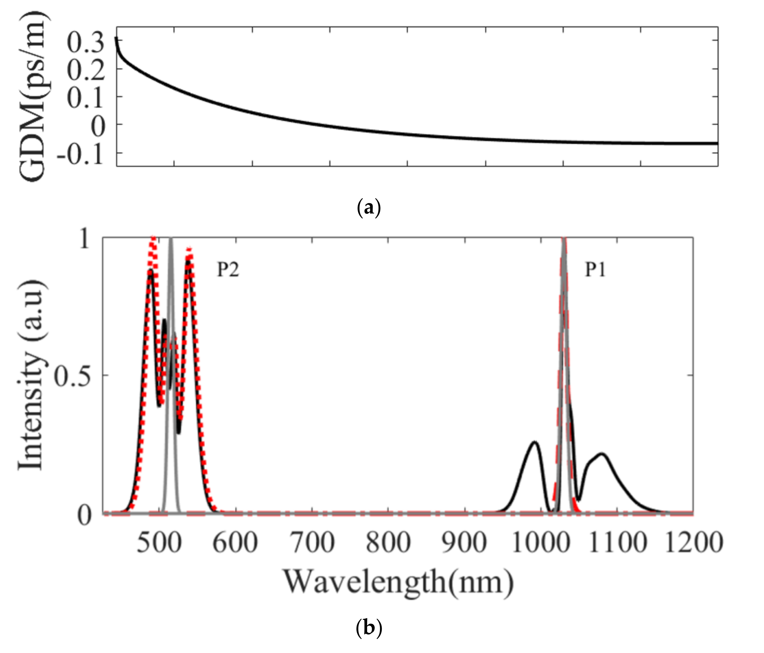
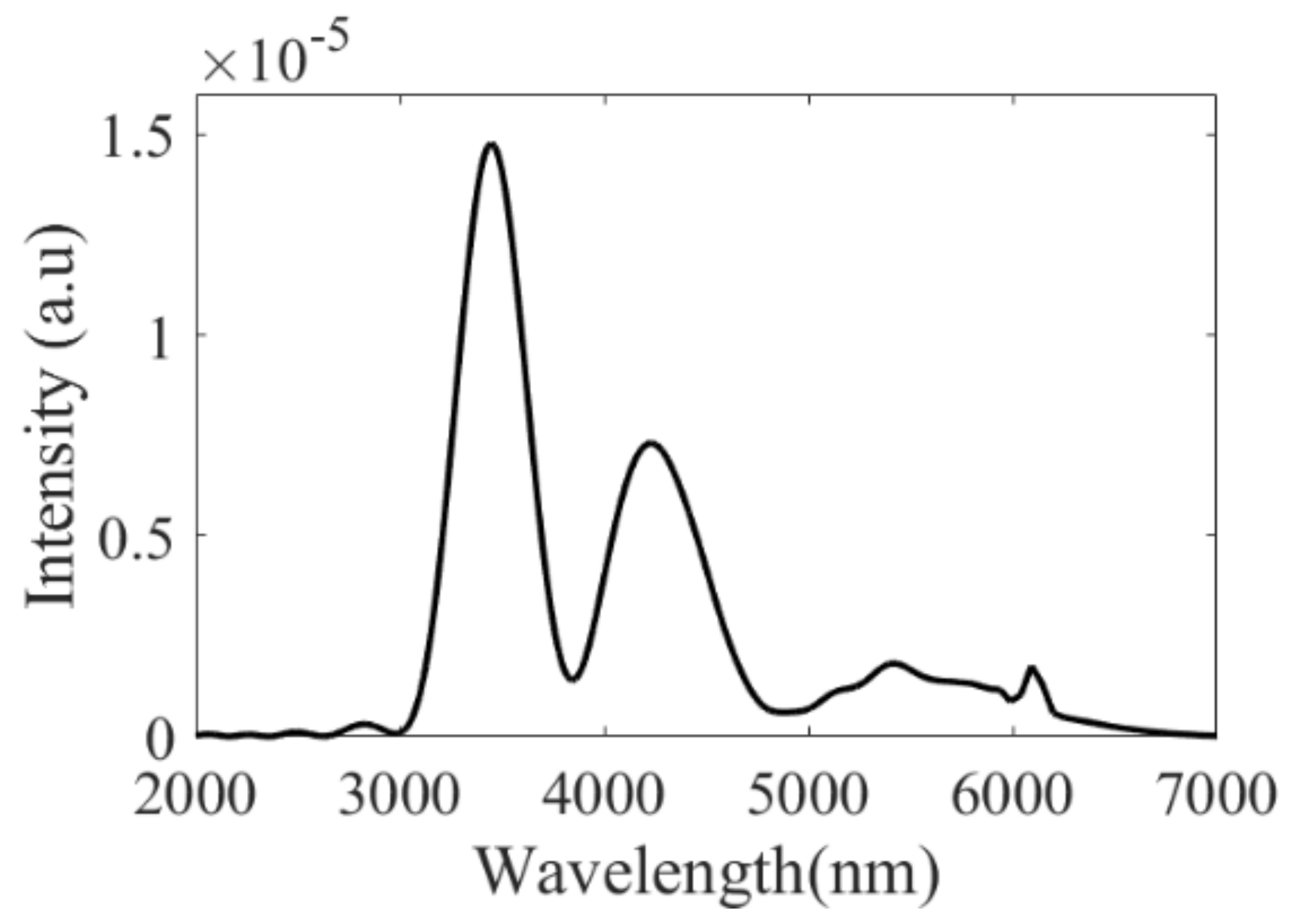
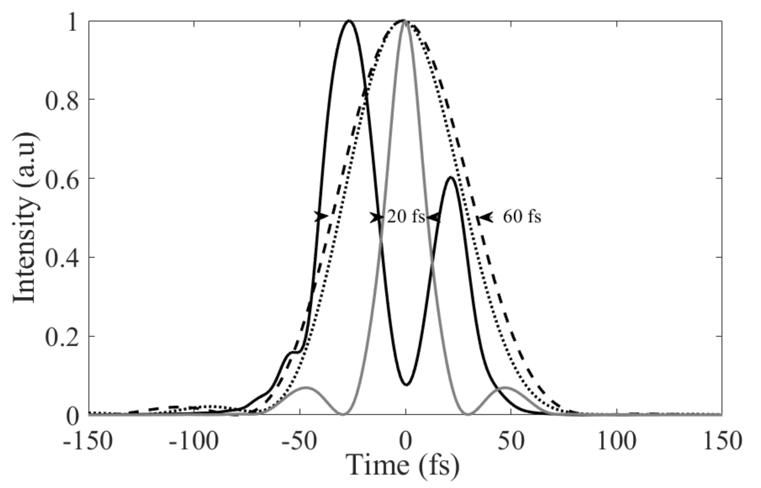
3.3. Pulse Properties of the Filtered Mid-Infrared Continuum

At the output of the HC-PCF, the MIR band is selected with a flat-top bandpass filter and the pulse shape is directly calculated. By selecting the MIR band between 3 and 5 µm, the temporal shape exhibits two peaks separated by 48 fs (blak solid-line in Figure 7). This structured temporal profile is due to the uncompensated phase acquired during the propagation and nonlinear conversion in the fiber. At the HC-PCF output, the accumulated phase can be compensated in order to reach an ultra-short pulse duration of ~20 fs (grey solid-line in Figure 7). When each lobe is filtered, the temporal profile has a bell-shape with a duration of ~60 fs at 3.4 µm or 4.2 µm without any phase compensation (black dashed and dotted-lines-Figure 7). An energy of a few nJ is obtained at the fiber output. Therefore, this scheme is highly desirable to develop a simple and robust pre-amplifier to seed a subsequent ultra-fast amplifier in the MIR.

4. Conclusions

We numerically demonstrated that ultra-short pulses at 3 and 4 µm can be generated through the interaction of a fundamental pulse and its harmonics in a HC-PCF filled with argon. The generation process originates from a cascaded nonlinear phenomenon starting from spectral broadening of the two pulses followed by an induced phase-matched four wave-mixing. The selected MIR band can directly provide sub-60 fs pulses and a duration of ~20 fs is expected if a system of phase compensation is used. This technique can be easily implemented since it relies on available laser systems and state-of-the-art anti-resonant fibers. The method is very promising to access MIR spectral ranges in the ultra-short pulse regime in a robust fiber system.

Author Contributions

C.F.-D., O.Z.-M. and D.B. conceived, developed the model and performed the full simulation; C.F.-D. and D.B. analyzed the data and wrote the manuscript. D.B. and P.M. supported this project. P.M. and O.Z.-M. discussed the results, and reviewed the manuscript. All authors have read and agreed to the published version of the manuscript.

Funding

This research was funded by the ANR (ANR-10-IDEX-03-02, ANR-17-EURE-0002,) and Bourgogne Franche-Comté council (SUM Project).

Institutional Review Board Statement

Not applicable.

Informed Consent Statement

Not applicable.

Data Availability Statement

Data available on request.

Conflicts of Interest

The authors declare no conflict of interest.

References

  1. Woodward, R.I.; Majewski, M.R.; Hudson, D.D.; Jackson, S.D. Swept-wavelength mid-infrared fiber laser for real-time ammonia gas sensing. APL Photonics 2019, 4, 020801. [Google Scholar] [CrossRef] [Green Version]
  2. Baldauf, N.A.; Rodriguez-Romo, L.A.; Yousef, A.E.; Rodriguez-Saona, L.E. Serovars by Fourier transform mid-infrared spectrocopy. Appl. Spec. 2006, 60, 592–598. [Google Scholar] [CrossRef]
  3. Müller-Werkmeister, H.M.; Li, Y.-L.; Lerch, E.-B.W.; Bigourd, D.; Bredenbeck, J. Ultrafast hopping from band to band: Assigning infrared spectra based on vibrational energy transfer. Angew. IE Chem. 2013, 52, 6214–6217. [Google Scholar] [CrossRef]
  4. Koulouklidis, D.A.; Gollner, C.; Shumakova, V.; Fedorov, V.Y.; Pugžlys, A.; Baltuška, A.; Tzortzakis, S. Observation of extremely efficient terahertz generation from mid-infrared two-color laser filaments. Nat. Commun. 2020, 11, 292. [Google Scholar] [CrossRef] [PubMed] [Green Version]
  5. Zlatanovic, S.; Park, J.S.; Moro, S.; Chavez Boggio, J.M.; Divliansky, I.B.; Alic, N.; Mookherjea, S.; Radic, S. Mid-infrared wavelength conversion in silicon waveguides using ultra-compact telecom-band-derived pump source. Nat. Photon. 2010, 4, 561–564. [Google Scholar] [CrossRef]
  6. Kowligy, S.A.; Lind, A.; Hickstein, D.D.; Carlson, D.R.; Timmers, H.; Nader, N.; Cruz, F.C.; Ycas, G.; Papp, S.B.; Diddams, S.A. Mid-infrared frequency comb generation via cascaded quadratic nonlinearities in quasi-phase-matched waveguides. Opt. Lett. 2018, 43, 1678–1681. [Google Scholar] [CrossRef] [Green Version]
  7. McCarthy, J.E.; Bookey, H.T.; Psaila, N.D.; Thomson, R.R.; Kar, A.K. Mid-infrared spectral broadening in an ultrafast laser inscribed gallium lanthanum sulphide waveguide. Opt. Express 2012, 20, 1545–1551. [Google Scholar] [CrossRef] [PubMed] [Green Version]
  8. Kubat, I.; Petersen, C.R.; Møller, U.V.; Seddon, A.; Benson, T.; Brilland, L.; Méchin, D.; Moselund, P.M.; Bang, O. Thulium pumped mid-infrared 0.9–9 μm supercontinuum generation in concatenated fluoride and chalcogenide glass fibers. Opt. Express 2014, 22, 3959–3967. [Google Scholar] [CrossRef] [Green Version]
  9. Debord, B.; Alharbi, M.; Vincetti, L.; Husakou, A.; Fourcade-Dutin, C.; Hoenninger, C.; Mottay, E.; Gérôme, F.; Benabid, F. Multi-meter fiber-delivery and pulse self-compression of milli-Joule femtosecond laser and fiber-aided laser-micromachining. Opt. Express 2014, 22, 10735–10746. [Google Scholar] [CrossRef]
  10. Maurel, B.; Delahaye, F.; Amrani, F.; Debord, B.; Gérôme, F.; Benabid, F. 2–3 µm wavelength-range low-loss inhibited-coupling hollow-core fiber. In Proceedings of the CLEO: Sciences and Innovations, San Jose, CA, USA, 13–18 May 2018. [Google Scholar]
  11. Yu, F.; Wadsworth, W.J.; Knight, J.C. Low loss silica hollow core fibers for 3–4 μm spectral region. Opt. Express 2012, 20, 11153–11158. [Google Scholar] [CrossRef] [Green Version]
  12. Yu, F.; Knight, J.C. Negative curvature hollow-core optical fiber. IEEE J. Sel. Top. Quantum Electron. 2016, 22, 146–155. [Google Scholar] [CrossRef] [Green Version]
  13. Adamu, A.I.; Habib, M.S.; Petersen, C.R.; Lopez, J.E.A.; Zhou, B.; Schülzgen, A.; Bache, M.; Amezcua-Correa, R.; Bang, O.; Markos, C. Deep-UV to mid-IR supercontinuum generation driven by mid-IR ultrashort pulses in a gas-filled hollow-core fiber. Sci. Rep. 2019, 9, 1–9. [Google Scholar]
  14. Klimczak, M.; Dobrakowski, D.; Ghosh, A.; Stępniewski, G.; Pysz, D.; Huss, G.; Sylvestre, T.; Buczyński, R. Nested capillary anti-resonant silica fiber with mid-infrared transmission and low bending sensitivity at 4000 nm. Opt. Lett. 2019, 44, 4395–4398. [Google Scholar] [CrossRef]
  15. Cassataro, M.; Novoa, D.; Günendi, M.C.; Edavalath, M.N.; Frosz, M.H.; Travers, J.C.; Russell, P.S. Generation of broadband mid-IR and UV light in gas-filled single-ring hollow-core PCF. Opt. Express 2017, 25, 7637–7644. [Google Scholar] [CrossRef] [Green Version]
  16. Michieletto, M.; Lyngsø, J.K.; Jakobsen, C.; Lægsgaard, J.; Bang, O.; Alkeskjold, T.T. Hollow-core fibers for high power pulse delivery. Opt. Express 2016, 24, 7103–7119. [Google Scholar] [CrossRef] [Green Version]
  17. Uebel, P.; Günendi, M.C.; Frosz, M.H.; Ahmed, G.; Edavalath, N.N.; Ménard, J.M.; Russell, P.S.J. Broadband robustly single-mode hollow-core PCF by resonant filtering of higher-order modes. Opt. Lett. 2016, 41, 1961–1964. [Google Scholar] [CrossRef] [PubMed] [Green Version]
  18. Balciunas, T.; Fourcade-Dutin, C.; Fan, G.; Witting, T.T.; Voronin, A.A.; Zheltikov, A.M.; Gerome, F.; Paulus, G.G.; Baltuska, A.; Benabid, F. A strong-field driver in the single-cycle regime based on self-compression in a kagome fibre. Nat. Commun. 2015, 6, 1. [Google Scholar] [CrossRef] [Green Version]
  19. Köttig, F.; Novoa, D.; Tani, F.; Günendi, M.C.; Cassataro, C.; Travers, J.C.; Russell, P.S.J. Mid-infrared dispersive wave generation in gas-filled photonic crystal fibre by transient ionization-driven changes in dispersion. Nat. Commun. 2017, 8, 813. [Google Scholar] [CrossRef] [PubMed]
  20. Hasan, M.I.; Akhmediev, N.; Mussot, A.; Chang, W. Midinfrared pulse generation by pumping in the normal dispersion regime of a gas filled hollow core fiber. Phys. Rev. Appl. 2019, 12, 014050. [Google Scholar] [CrossRef]
  21. Ding, X.; Habib, M.S.; Amezcua-Correa, R.; Moses, J. Near-octave intense mid-infrared by adiabatic down-conversion in hollow anti-resonant fiber. Opt. Lett. 2019, 44, 1084–1087. [Google Scholar] [CrossRef]
  22. Hasan, M.I.; Akhmediev, N.; Chang, W. Empirical Formulae for Dispersion and Effective Mode Area in Hollow-Core Antiresonant Fibers. J. Lightw. Technol. 2018, 36, 4060–4065. [Google Scholar] [CrossRef]
  23. Marcatelli, E.A.J.; Schmeltzer, R.A. Hollow metallic and dielectric waveguides for long distance optical transmission and lasers. Bell Syst. Tech. J. 1964, 64, 1783–1809. [Google Scholar] [CrossRef]
  24. Dudley, J.M.; Genty, G.; Coen, S. Supercontinuum generation in photonic crystal fiber. Rev. Mod. Phys. 2006, 79, 1135–1184. [Google Scholar] [CrossRef]
  25. Matsubara, E.; Yamane, K.; Sekikawa, T.; Yamashita, M. Generation of 2.6 fs optical pulses using induced-phase modulation in a gas-filled hollow fiber. J. Opt. Soc. Am. B 2007, 24, 985–989. [Google Scholar] [CrossRef]
  26. Fourcade-Dutin, C.; Imperio, A.; Dauliat, R.; Jamier, R.; Muñoz-Marco, H.; Pérez-Millán, P.; Maillotte, H.; Roy, P.; Bigourd, D. Temporal Distribution Measurement of the Parametric Spectral Gain in a Photonic Crystal Fiber Pumped by a Chirped Pulse. Photonics 2019, 6, 20. [Google Scholar] [CrossRef] [Green Version]
  27. Vanvincq, O.; Fourcade-Dutin, C.; Mussot, A.; Hugonnot, E.; Bigourd, D. Ultrabroadband fiber optical parametric amplifiers pumped by chirped pulses. Part 1: Analytical model. J. Opt. Soc. Am. B 2015, 32, 1479–1487. [Google Scholar] [CrossRef]
  28. Webb, K.E.; Xu, Y.Q.; Erkintalo, M.; Murdoch, S.G. Generalized dispersive wave emission in nonlinear fiber optics. Opt. Lett. 2013, 38, 151–153. [Google Scholar] [CrossRef] [PubMed]
  29. Robert, P.; Fourcade-Dutin, C.; Dauliat, R.; Jamier, R.; Muñoz-Marco, H.; Pérez-Millán, P.; Dudley, J.M.; Roy, P.; Maillotte, H.; Bigourd, D. Spectral correlation of four-wave mixing generated in a photonic crystal fiber pumped by a chirped pulse. Opt. Lett. 2020, 45, 4148–4151. [Google Scholar] [CrossRef]
Figure 1. Group velocity dispersion as a function of the wavelength for the HC-PCF filled with argon at a pressure of 5 bar. The grey area represents the resonant band. The inset represents a schematic view of the fiber with the LP01 mode at 1030 nm.
Fibers 09 00021 g001
Figure 2. (a) Group delay mismatch as a function of the wavelength. (b) Output spectrum for L = 50 cm when P1 (red dashed-line), P2 (red dotted-line) or both pulses (black solid-line) are injected in the 50 cm long HC-PCF. The input spectra are also displayed (grey solid-lines).
Fibers 09 00021 g002
Figure 3. Total spectrum as a function of the fiber length with a logarithmic scale. Zones 1, 2 and 3 correspond to some generated bands in the UV, near IR and MIR. The light-blue line represents the absorption band of the HC-PCF.
Fibers 09 00021 g003
Figure 4. (a) Coherence length (1/κ) as a function of the pump P1 wavelength for a constant peak power of 63 MW (from Equation (5). (b) Phase mismatch of the dispersive wave (ΔβDW) as a function of the wavelength for the pump P2 (from Equation (6).
Fibers 09 00021 g004
Figure 5. MIR spectrum at the HC-PCF output.
Fibers 09 00021 g005
Figure 6. Spectrogram at the output HC-PCF. The light-blue line represents the absorption band of the HC-PCF.
Fibers 09 00021 g006
Figure 7. Temporal profiles of the MIR band (black solid-line) and filtered spectra at 3.4 or 4.2 µm (black dashed or dotted line). The grey solid-line corresponds to the pulse profile without the filter when the total phase is compensated.
Fibers 09 00021 g007
Publisher’s Note: MDPI stays neutral with regard to jurisdictional claims in published maps and institutional affiliations.

