Article

Flexural Strength of Damaged RC Beams Repaired with Carbon Fiber-Reinforced Polymer (CFRP) Using Different Techniques

by
Abbas Yahya Turki
* and
Mahdi Hameed Al-Farttoosi
Department of Civil Engineering, University of Baghdad, Baghdad 10071, Iraq
*
Author to whom correspondence should be addressed.
Fibers 2023, 11(7), 61; https://doi.org/10.3390/fib11070061
Submission received: 4 June 2023 / Revised: 30 June 2023 / Accepted: 12 July 2023 / Published: 14 July 2023

Abstract

:
In this study, an experimental program was developed to investigate the flexural behavior of pre-damaged reinforced concrete (RC) beams that had been repaired and strengthened using carbon fiber-reinforced polymer (CFRP) laminates under a monotonic load. Two techniques were used: externally bonded reinforcement (EBR) and near-surface-mounted (NSM) reinforcement, to repair and strengthen the tested beams. The experimental program involved casting and testing nine simply supported RC rectangular beams; one beam was considered as the reference beam and did not undergo additional strengthening, and the remaining beams were strengthened using CFRP laminates. These eight beams were divided into two main groups for the purposes of strengthening: beams for which the EBR technique was used, and beams for which the NSM technique was used. The primary variables observed in the EBR and NSM groups included four damage percentages obtained according to the preload (20, 40, 60, and 80%) from the ultimate load carried by the reference beam. The experimental results show that decreasing the damage percentage leads to an increase in ultimate strength from about 3.6% to 17.2% for the beams repaired using the EBR technique and from 27.6% to 57% for the beams repaired using the NSM technique; additionally, the NSM method was more effective than the EBR method in terms of the flexural strength and mode of failure. However, using CFRP laminates enhances the flexure capacity of strengthened RC beams.

1. Introduction

The maintenance, repair, and improvement of structural components may be one of the most important tasks in civil engineering. Additionally, according to new design codes, structures that were built in the past using old design codes in different parts of the world must be made safer. Damage to concrete buildings can result from natural events such as earthquakes, fires, or storms, as well as from mistakes made during the design process. One example of a design mistake is when there is not enough strengthened steel or fiber in the concrete parts used during construction to hold loads. The use of fiber-reinforced polymers (FRP) to retrofit and rehabilitate reinforced concrete (RC) structures represents a new technology that is in competition with the traditional approach. Compared to steel plate bonding or jacketing, the advantages of using these advanced composite materials for retrofitting are due to their unique properties. An extensive amount of research has been conducted to analyze how well carbon fiber-reinforced polymers (CFRPs) may function as an outside reinforcement for reinforced concrete (RC) beams [1,2,3,4,5,6].
Many techniques have been investigated to determine how to strengthen and rehabilitate beams using FRP composites. Both the EBR and NSM techniques are viewed as good strengthening systems due to their ability to enhance the shear and flexural capacity of RC structures [7,8,9,10,11,12,13,14,15,16,17,18,19,20]. The major concern surrounding adhesively bonding plates to the external surface of reinforced concrete beams is the premature debonding of the plates, which is a unique form of failure observed in plated beams [21].
Researchers have looked at the behavior of RC beams that have been pre-damaged or preloaded and then repaired with CFRP using the EBR and NSM methods. In the research by Li et al. [22], 22 beams were tested to determine how preload affects the flexural load-carrying capability of CFRP-strengthened RC beams. Their results showed that preload levels below 80% of the original beam’s yield strength do not affect flexural capacity, but that levels exceeding 90% significantly reduce it.
To determine the effect of embedding CFRP rods as a method of NSM reinforcement for strengthening/repairing RC beams with various degrees of loading damage, and to compare the results obtained with RC beams that had not been preloaded, an experimental program was carried out by Morsy et al. [23]. In this experiment, CFRP rods were added to reinforce six steel beams. Three strengthened and three preloaded beams were tested, showing an increased flexibility and a capacity that was 33.33% higher compared to the control beam. Preloading had minimal impact on strength improvement. Failure analysis revealed flexure-related failure, indicating that embedded FRP rods are preferable to near-surface-mounted ones in preventing brittle failure and in minimizing CFRP bar debonding.
In the study by Meikandaan et al. [24], the authors examined the repair of damaged reinforced concrete beams using carbon fiber-reinforced plastic (CFRP) laminates. Different parameters such as damage degree, laminate width, and concrete strength were investigated. The effect of damage degree on load capacity was evaluated, and failure mechanisms such as flaking and debonding were observed and found to be influenced by laminate width.
In the study by Yu et al. [25], CFRP sheets were used to repair flexural damage in pre-damaged RC beams. The failure mechanisms, deflection, and load-carrying capacity depended on the pre-damage level, sheet layer, and reinforcement ratio. Pre-damage testing and larger CFRP layers improved performance, but higher pre-damage levels reduced it. A formula was developed to estimate flexural capacity under the condition of high pre-damage levels, resulting in good performance.
Gaber et al. [26] investigated the use of NSM strips to strengthen reinforced concrete beams. Preloaded beams were repaired using NSM-CFRP strips, resulting in an improved load-carrying capacity, fracture resistance, and deflection performance compared to the control beams. The strengthening effect varied depending on the preloading level.
Benjeddou et al. [27] investigated the flexural behavior of repaired reinforced concrete (RC) beams using CFRP laminates and their contribution to restoring the strength and rigidity of the studied beams. The damage degree, which ranged from 0% to 100% of the control beam’s ultimate load capacity, was a key parameter. The authors found that externally bonded CFRP laminates effectively repaired RC beams with varying degrees of damage, successfully restoring their mechanical performance. Fayyadh et al. [28] studied the effectiveness of CFRP-repaired RC beams and assessed them at different damage levels. Four beams were used: one without CFRP sheets and three beams that had been repaired after pre-damage. The study compared flexural stiffness recovery, crack patterns, load capacity, and failure modes, finding that CFRP repair was effective and increased the ultimate capacity regardless of the pre-repair damage level.
In this study, the flexural strength of damaged RC beams repaired using carbon fiber-reinforced polymer (CFRP) via different techniques was investigated, with the un-strengthened beams being subjected to preloads with varying percentages of the ultimate load of the reference beam to represent the pre-damage of the beams. These beams were strengthened and subjected to monotonic load until failure.

2. Experimental Program

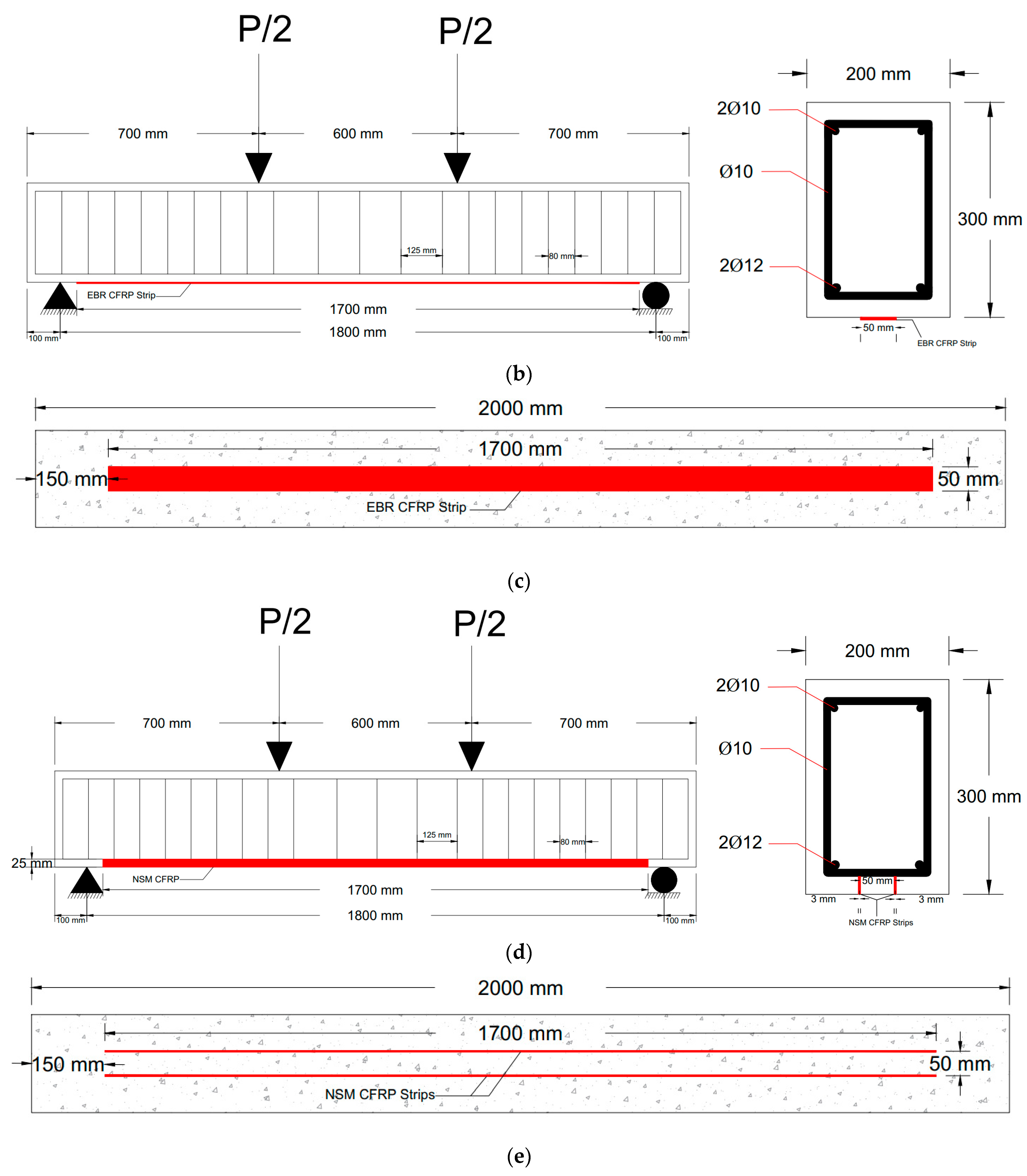
2.1. Beams Geometry and Details

Nine rectangular RC beams were cast and tested in the supplementary work, comprising one reference beam and eight beams divided into two groups that had been strengthened with CFRP. The main variable in these groups was the percentage of damage (preload) (20, 40, 60, and 80%) and the strengthening techniques with EBR and NSM, resulting from the ultimate load of the reference beam. The details of the groups and the beam configurations are shown in Table 1.
All of the tested beams had the same dimensions (200 mm × 300 mm × 2000 mm) and reinforcement type. The simply supported beam was subjected to a two-point load during the test. After damage induction, all beams in the EBR group were strengthened with an external CFRP strip with a width of 5 cm and length of 170 cm that was glued to the bottom face of the beam, while the beams in the NSM group were strengthened via the NSM technique, using two CFRP strips with a width of 2.5 cm and length of 170 cm that were glued inside the concrete cover of the bottom face of the beam (2.5 cm). The steel bars used to reinforce all of the beams were 2Ø12 at the bottom and 2Ø10 at the top, with stirrup Ø10 spacing of 80 mm near the support and 125 mm at the middle part of the beam; the concrete cover was 2.5 cm. Figure 1 shows the beam’s cross-section, reinforcement, and CFRP strengthening.

2.2. Materials Properties

2.2.1. Reinforcement Steel Bars

Two sizes of deformed bars were used, with nominal diameters of 12 mm and 10 mm, respectively. Tensile tests were conducted on these bars using TORSEE’S universal test machine, and the average characteristics of three samples for each rebar diameter are presented in Table 2. The testing was carried out according to the American Standard Specification for Deformed Steel Bars ASTM A615/A615M [29].

2.2.2. Concrete

Different specimens were prepared during beam casting and were subjected to testing to evaluate the concrete properties. The tests aimed to determine the compressive strength, splitting tensile strength, modulus of rupture, and modulus of elasticity of the concrete. For the compressive strength, three standard cubes measuring 150 × 150 × 150 mm, three prismatic specimens with the dimensions of 100 × 100 × 400 mm, and three standard cylinders measuring 150 × 300 mm were tested using a universal compression machine. The splitting tensile strength of the concrete was determined per ASTM C496/C496M [30]. The modulus of elasticity was calculated using Equation (1), as specified in ACI 318M-19 [31]. Finally, the modulus of rupture was determined following the procedures outlined in ASTM C293/C293M [32]. The mechanical properties of the concrete, including the compressive strength, splitting tensile strength, modulus of rupture, and modulus of elasticity, are summarized in Table 3.
E c = 4700 f c

2.2.3. CFRP Laminates and Epoxy Adhesive

In this study, Sika®CarboDur®S was the CFRP laminate used for improving the flexural strength; the mechanical properties of the CFRP are presented in Table 4; when improving the flexural strength, Epoxy Sikadur-30LP was used as a bonding material between the concrete and CFRP laminate. This adhesive material consists of two parts: part A, which is white in color, and part B, which is black in color. These two parts were mixed in a ratio of 3A:1B. The mechanical and physical characteristics of the bonding resin are presented in Table 5.

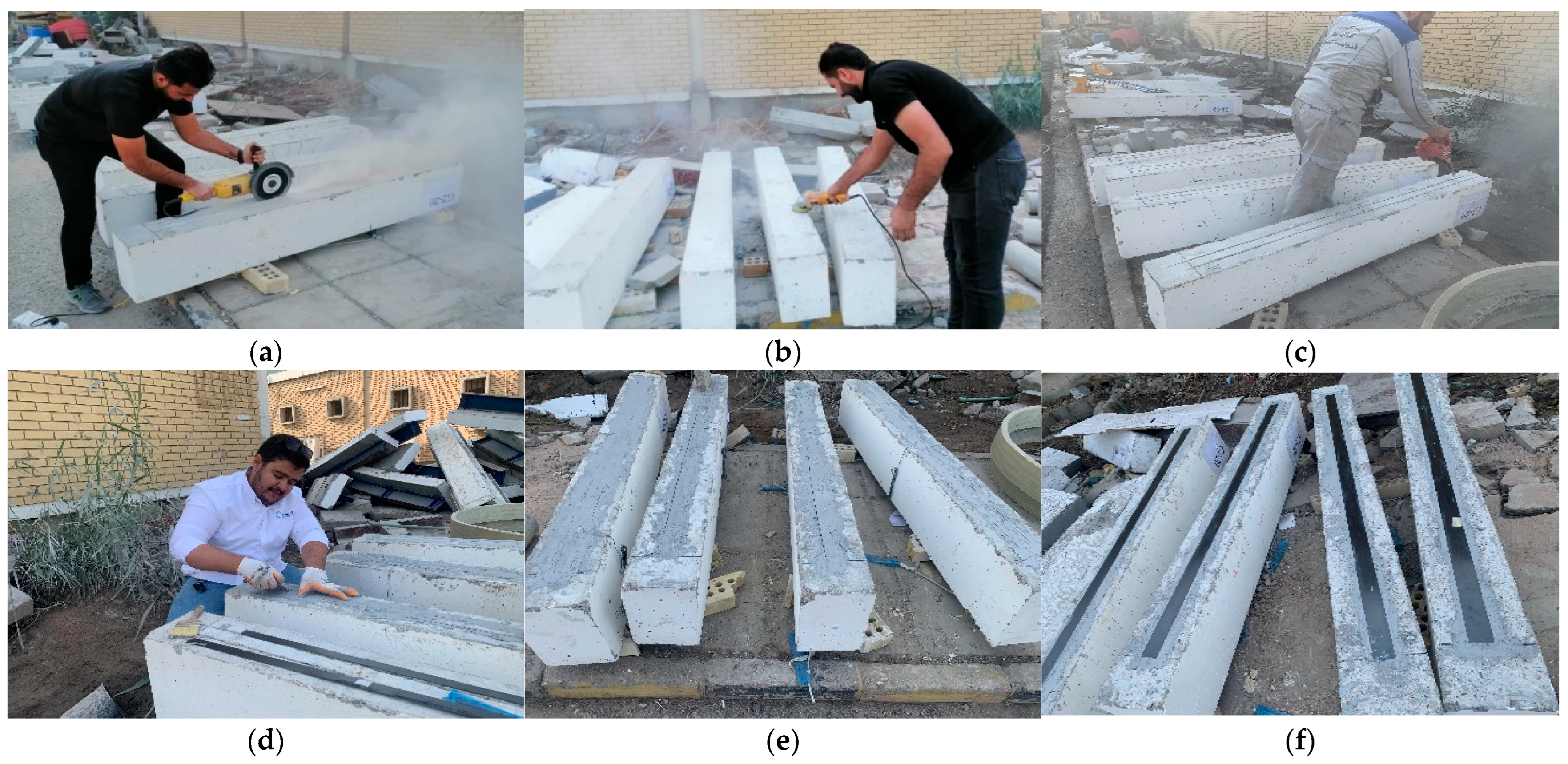
2.3. Installation of CFRP

The damaged (preloaded) beams were strengthened with CFRP using the EBR and NSM techniques; in the EBR technique, the surface is first roughened with a grinder machine and cleaned to remove any dust; then, the RC beams are marked in order for the laminate to be installed in the correct place. The laminate is installed on the bottom face of the concrete using epoxy. In the NSM technique, the CFRP laminates are cut into two strips from the middle after damaged (preloading), each one with a width of 25 mm; then, at the bottom face of the RC beams, two grooves that are 25 mm in depth are made, and the strips are installed into these grooves using the epoxy adhesive. For both the EBR and NSM strengthening techniques, the CFRP was 170 cm in length; the installation process is depicted in Figure 2.

2.4. Test Setup and Incrementations

To perform the testing, all of the reinforced concrete (RC) beams were simply supported beams that were then subjected to monotonic loads using a spreader loading beam and TORSEE’S universal test machine with a capacity of 2000 kN. The applied load was measured using a load cell connected to a data acquisition system. To measure the deflections at the mid-span of each beam during the loading test, a linear displacement sensor (LVDT 100 mm) was used (as shown in Figure 3). Strain measurements were recorded on the concrete surface and on the steel rebars. For the concrete strain measurements, PL-60.011-5L strain gauges were utilized and placed on the top face of the specimens, specifically at the compression face. FLAB-5-11-3LJC-F-type electrical strain gauges with a base length of 5 mm were attached to the outer surface of the main longitudinal tensile steel reinforcement at the lower layer (as depicted in Figure 4). These strain gauges were sourced from Tokyo Measuring Laboratory (TML).

3. Testing Procedures

The testing procedures implemented in this study are represented in Figure 5.

4. Test Results and Discussion

4.1. Damage Stage

The reference beam was tested up to failure to determine the ultimate flexure capacity. Figure 6 shows the load–deflection curve of beam control failure obtained with a load of 140.1 kN and failure by the steel reinforcement to improve yield, followed by concrete cursing. The damage (preload) percentage (20, 40, 60, and 80%) of the ultimate load of the reference beam was chosen to obtain the damaged (preloaded) RC beams for both the EBR and NSM groups (see Figure 7).

First Crack Load and Crack Pattern

The experimental results showed that the first flexural crack occurred at the first loading stage (preloading) for all beams except those with 20% damage, which cracked in the second loading stage.
The first flexural crack appeared at an applied load of 33 kN. The ratio of the first crack load (Pcr) to the ultimate load (Pu) was approximate for the reference beam. For the beams in the EBR group, the first flexural crack occurred within the range of 30 to 34 kN. Similarly, for the beams in the NSM group, the first flexural crack appeared within the range of 31 to 35 kN. Figure 8 illustrates the load levels corresponding to the cracking at the damage stage (preloading).

4.2. Strengthening Stage

4.2.1. Deformability of the Tested Beams under the Applied Load

Deformability can refer to the strain in a body, the curvature in a section, and the rotation and deflection of the member. Figure 9 shows the relationships between applied load and mid-span deflection from zero loading to the failure stage for all of the tested beams. Because the load behavior could not be regulated after the peak in all of the tested beams, the data shown in the figures ended at the failure load and its corresponding deflection value. The selected serviceability limit was the ultimate experimental load divided by 1.7, as advised by several investigators, such Mansur et al. [33], because no undesirable cracking or deformation was observed. As a result, Table 6 summarizes the relevant mid-span deflection and ultimate applied load for all of the tested beams. The load chosen for the ultimate load of the reference beam (140.1 kN) is important to compare deflections at a constant load.
The Initial deflection of the beams was found to be linear in all circumstances. The deflection of the tested beams remained semi-linear after reaching the cracking load but at a much shallower angle than during the pre-cracking period. Additionally, the deflection curves began to diverge from one another based on the cracking severity and stiffness deterioration. Beams in the same family showed varying degrees of linear section inclination. The deflection behavior of the tested beams deviated from a linear response when the applied loads became closer to the ultimate load, entering a nonlinear zone.
At the service load stage, the mid-span deflection decreased by 4.3, 4.6, 16, 21, 29, 29.3, 33.9, and 40.2% for B-EBR-80, B-EBR-60, B-EBR-40, B-EBR-20, B-NSM-80, B-NSM-60, B-NSM-40, and B-NSM-20, respectively, with regard to the reference beam, BC1.
When the reference beam was at the ultimate load (140.1 kN), the mid-span deflection decreased by 24.8, 37.9, 43.4, 50.3, 57.7, 66.8, 74, and 76.9% for B-EBR-80, B-EBR-60, B-EBR-40, B-EBR-20, B-NSM-80, B-NSM-60, B-NSM-40, and B-NSM-20, respectively, with regard to the reference beam, BC1.
Figure 9 shows how the damage affects load deflection at the middle of the span for all reinforced beams. Load–deflection graphs show that almost all of the beams have the same stiffness in the elastic region. However, after the tension support yields, the damage percentage is inversely related to beam stiffness, meaning that the beam bends less under the same load.
The near-surface-mounted technique is an innovative approach that significantly enhances the flexural strength of reinforced concrete beams. This method involves cutting grooves into the underside of the beam, inserting CFRP strips into these grooves, and securely bonding them to the concrete using a suitable adhesive agent. Comparing the NSM strengthening method to the externally bonded reinforcement method, the former proved to be more effective, and this is because NSM provides a larger bond area, is less susceptible to debonding, and is less disruptive. The CFRP reinforcement is embedded in the concrete, providing a larger bond area than EBR, as shown in Figure 10. The figure shows that as the damage percentage increased (20%, 40%, 60%, and 80%), the NSM technique resulted in a higher percentage increase in the ultimate load capacity, with values of 34%, 31%, 33%, and 23%, respectively. At the ultimate load, the mid-span deflection decreased by 8.3, 12.9, 15.7, 20, 18.9, 21.4, 23.4 and 29.7% for B-EBR-80, B-EBR-60, B-EBR-40, B-EBR-20, B-NSM-80, B-NSM-60, B-NSM-40, and B-NSM-20, respectively, with regard to the reference beam, BC1.

4.2.2. Load-Carrying Capacity and Failure Mode

In this study, failure load was determined as the maximum applied static load that caused a significant reduction in strength and that ultimately led to beam collapse.
It should be noted that throughout the experimental investigation, only flexural fractures were found in the tested beams. Nearly vertical flexural fractures formed in the extreme tensile fibers at the base of the web section, close to the section with the largest bending moment, as the applied load caused considerable flexural stresses in the mid-span area. Vertical flexural cracks multiplied under increasing loads and extended in length and splayed out toward the horizontal direction as the applied stress rose, evolving into flexural shear cracks.
These cracks resulted from the application of a load and seemed to grow in length based on the size of the cracked area, and the direction in which the cracks spread toward the direction of the applied force. As the load increased, the flexural fractures also tended to flatten, revealing a change in flexural shear behavior.
In the reference beam (BC1), failure was caused by cracks that started from the beam soffit at the largest bending moment; these cracks progressed toward the top zone due to steel yield, followed by compression failure at the load point (flexural failure).
While for the strengthened beam with EBR CFRP laminate in B-EBR-20, B-EBR-40, B-EBR-60, and B-EBR-80 at the damage percentages of 20, 40, 60, and 80%, respectively, failure was determined by intermediate flexure cracks, followed by the debonding of CFRP at the bottom of the beams strengthened with the CFRP laminate.
Finally, for the beams with NSM CFRP laminate B-NSM-20, B-NSM-40, B-NSM-60, and B-NSM-80 at the damage percentages of 20, 40, 60, and 80%, respectively, failure was indicated by concrete crushing, followed by a localized cover separation; in this mode of failure, a trapezoidal or triangular piece of concrete becomes separated from the beam due to the combination of bond cracks around the maximum moment area as well as shear and flexural cracks, with the last two crack types occurring before the first one.
Figure 11, Figure 12, Figure 13, Figure 14, Figure 15, Figure 16, Figure 17, Figure 18 and Figure 19 illustrate the failure mode and the crack patterns of each of the beams.
Table 7 shows that decreasing the percentage of damage leads to an increase in the ultimate strength of about 3.6, 7.2, 14.3, and 17.2% for beams with the damage percentages of 80, 60, 40, and 20%, respectively, concerning the reference beam in the EBR group. Additionally, decreasing the damage percentage led to a higher increase in the ultimate strength of about 27.6, 42.9, 49.5, and 57% for beams with the damage percentages of 80, 60, 40, and 20%, respectively, with regard to the reference beam in the NSM group.
The damage percentage is inversely proportional to beam stiffness. Additionally, the suggested NSM strengthening method was more effective than the EBR method (see Figure 20).

4.2.3. Load vs. Concrete Strain through Testing Monotonic Beams

Longitudinal concrete surface strain mid-span at the top of the beam was measured. This location was selected to better understand how the reinforced concrete beams respond, as well as their flexural behavior. To investigate the compression strain during loading stages, PL-60-11-5L-type strain gauges were fixed on the concrete surface at the selected location. Each measurement’s strain was allocated to the middle point of the present strain gauge length.
Cracks in concrete constructions may be either the consequence of water loss shrinkage or the effect of external stresses. Certain curing circumstances restrict or dictate the occurrence of the first type of crack. Since strain types in the longitudinal direction only provide a nominal value, they are ignored. During the loading test, it is clear that longitudinal compression stresses increased significantly. The diverging behavior of the curves is evidence of this.
Figure 21 shows the load versus longitudinal compressive concrete strains at the top mid-span in the beams from the EBR group, while Figure 22 shows the load versus longitudinal compressive concrete strains at the top mid-span in the beams from the NSM group.

4.2.4. Load vs. Mid-Span Strain of Longitudinal Bottom Steel Reinforcement

The strain was measured in the lower layer of the steel reinforcement (Ø12 mm) using electrical FLAB-5-11-3LJC-F-type strain gauges with a base length of 5 mm attached to the outward surface of the reinforcing bars. Figure 23 and Figure 24 demonstrate that all beams behave almost linearly at the start of loading up to about 30 kN and that the strains that develop are small. At higher loading stages, the reference beam that has not been strengthened shows a higher increase in strain than the strengthened beams. By reducing the strain at the same load level, decreasing the damage percentage makes it stiffer. At their maximum load, all of the beams in the flexural group were stronger than the yield strength of the steel bars (3385 με).
Figure 23 shows the load versus longitudinal compressive concrete strains at the top mid-span of the beams from the EBR group, while Figure 24 shows the load versus longitudinal compressive concrete strains at the top mid-span in the beams from the NSM group.

4.3. Stiffness

The stiffness of reinforced concrete (RC) beams is an important property that affects their behavior and performance. Stiffness is defined as the resistance of a material to deformation under an applied load. A body’s stiffness K is primarily determined by flexural stiffness, which measures the beam’s resistance to bending. Table 8 shows the stiffness of the beams during the service load and ultimate load stage. Adding CFRP to an RC beam increases its stiffness and load-carrying capacity by improving its flexural strength and ductility. In this study, CFRP was typically applied externally to the beam using the EBR and NSM methods. During loading, CFRP was bonded to the surface of the beam using a high-strength epoxy adhesive. See Figure 25, which shows a comparison of the stiffness values of the tested beams (where Ku: stiffness at the ultimate load stage, and Ks: stiffness at the service load stage).

4.4. Flexure Toughness

The area under the load–deflection curves was used to calculate the flexural toughness (total energy) of each beam in this investigation. This computation was achieved using AutoCAD. Overall, energy absorption capability is what is being referred to when describing a material’s flexural toughness. As a measure of the potential energy that may be stored in a loaded concrete structure, it is an important metric in the context of concrete structures. Both the maximum load value and the deflection at failure affect the absorbed energy, which is shown by the area under the load–deflection curve of the monotonic applied load. The total energies of the tested beams are listed in Table 9, and a comparison is shown in Figure 26. The flexural toughness of the beams in the NSM group was found to be superior to that of the EBR beams.

5. Conclusions

In this study, an experimental test investigated the flexural behavior of rectangular RC beams that had been damaged or preloaded at different percentages (20, 40, 60, and 80%) according to the ultimate failure load of the control reference beam; two different techniques were used in this study: EBR and NSM, which were implemented to improve the strength of the beams after applying the preload. The described experimental program includes one reference beam and eight beams divided into the EBR and NSM groups, and these beams were tested monotonically under two concentrated loads until failure. The main findings from this study are as follows:
  • The experimental results show how the repair with CFRP effectively strengthens the damaged RC beams using both techniques, EBR and NSM. Additionally, NSM was more effective than EBR. This is due to NSM providing a larger bond area, is less susceptible to debonding, and is less disruptive. The CFRP reinforcement is embedded in the concrete, providing a larger bond area than EBR.
  • The first flexural crack occurred during the first loading stage (preloading) for all beams except the beams with a damage (preload) percentage of 20%, which cracked during the second loading stage because of this percent of damage (preload), which is not enough to crack the beams.
  • The flexural strength and load-carrying capacity for the damaged (preloaded) beams for both groups after repairing with CFRP increased by 3.6 to 17.2% for the EBR group and 27.6 to 57% for the NSM group; this concluded that decreasing the percentage of the damage (preload) led to an increase of the ultimate loads of beams, respectively, based on the damage (preload) percent.
  • The stiffness of the repaired (strengthened) beams for both techniques increased after being repaired with CFRP compared to the reference beam at all load stages.
  • The flexural toughness of the beams in the NSM group was superior to that of the EBR beams and reference beam; but for the EBR compared to the reference beam, the total energy (toughness) was less than the reference beam.
  • The beams strengthened with CFRP exhibited lower deflections than the un-strengthened beam at all load stages because of the brittle nature of CFRP and bonding characteristics.
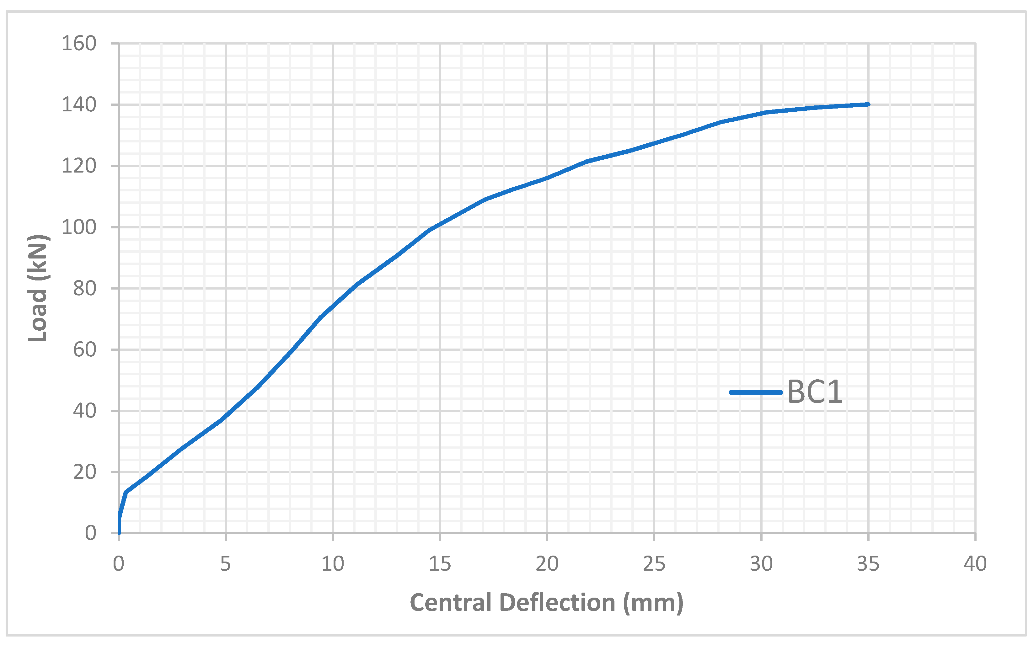
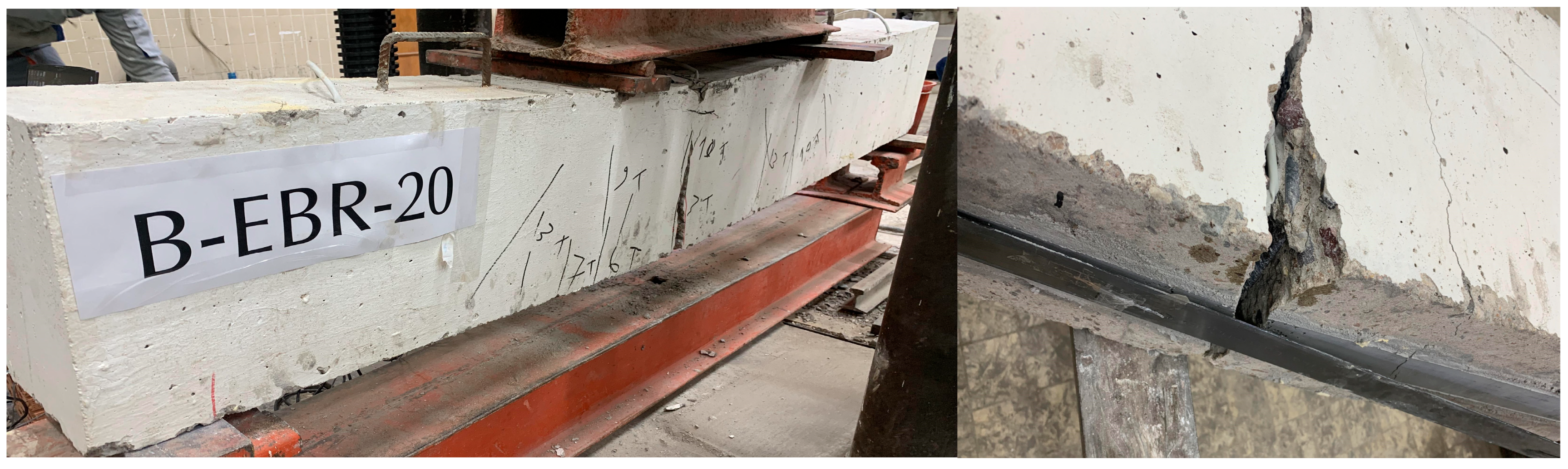
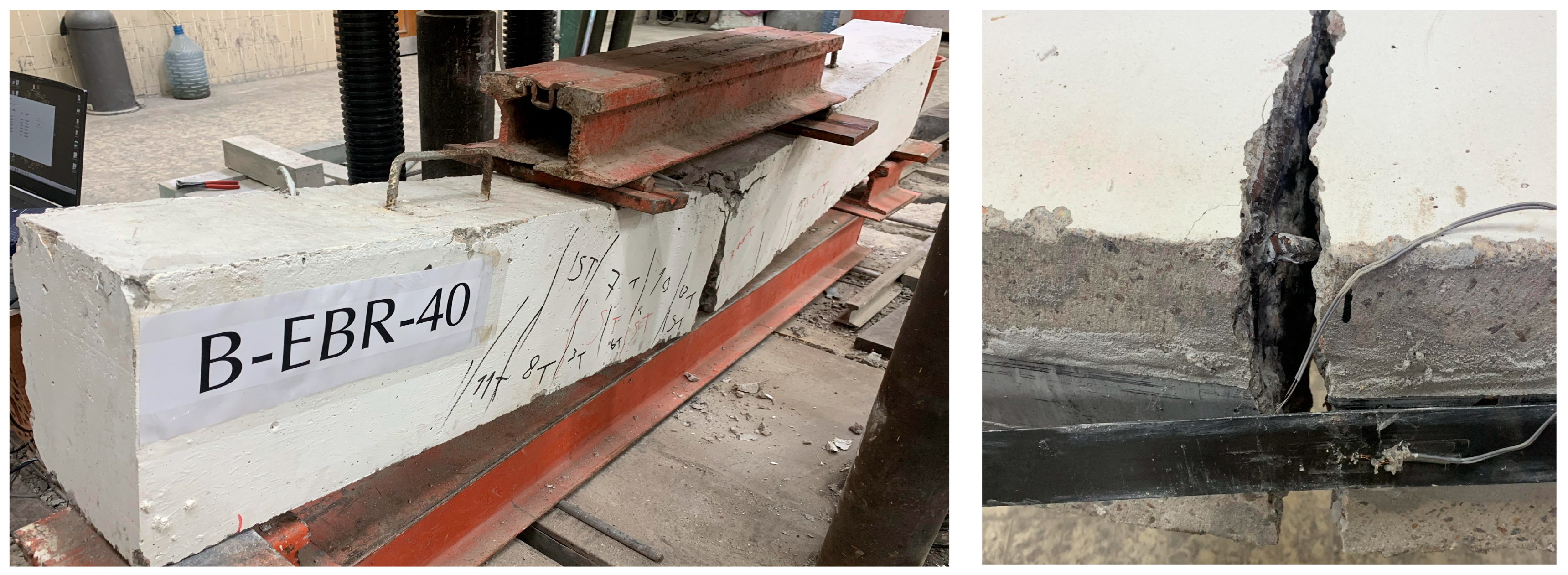
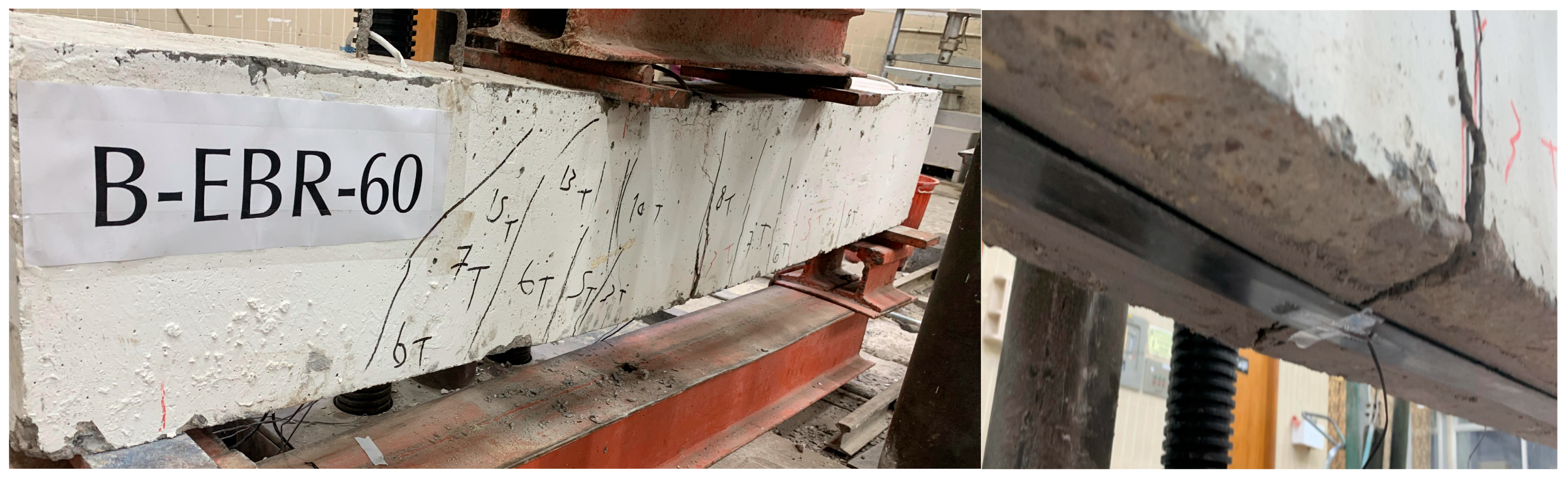
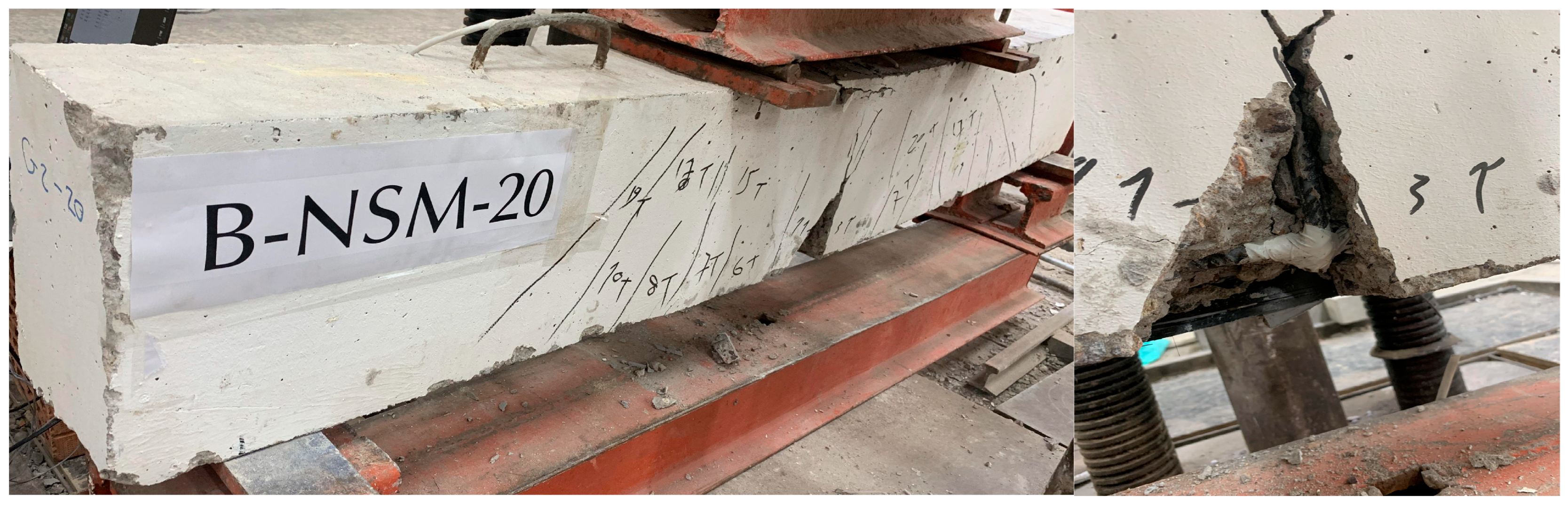
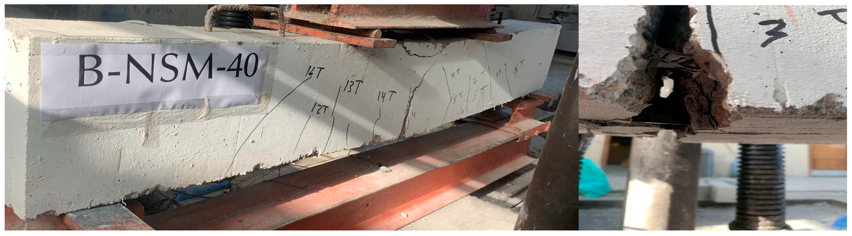
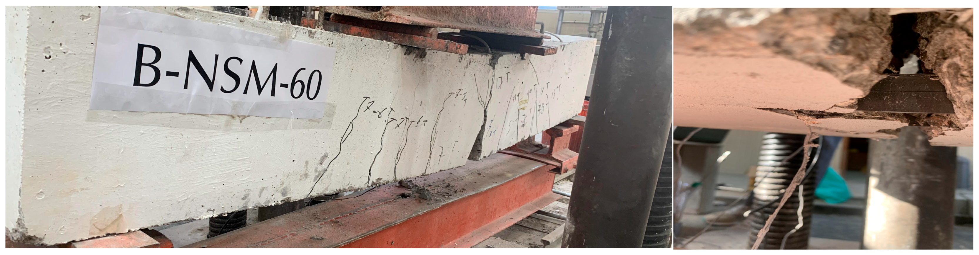
  • In the reference beam (BC1), failure was due to steel yield, followed by concrete crushing at the compression zone at the load point (flexural failure); for the EBR group, failure was determined by intermediate flexure cracks followed by the debonding of CFRP at the bottom of the beams strengthened with the CFRP laminate. Finally, NSM group failure was indicated by concrete crushing followed by a localized cover separation; in this mode of failure, a trapezoidal or triangular piece of concrete becomes separated from the beam due to the combination of bond cracks around the maximum moment area as well as shear and flexural cracks, with the last two crack types occurring before the first one.

Author Contributions

Investigation, A.Y.T.; resources, A.Y.T.; supervision, M.H.A.-F.; visualization, M.H.A.-F. and A.Y.T.; analysis, M.H.A.-F. and A.Y.T.; writing—original draft, A.Y.T.; writing—review and editing, A.Y.T. All authors have read and agreed to the published version of the manuscript.

Funding

This research received no external funding.

Institutional Review Board Statement

Not applicable.

Informed Consent Statement

Not applicable.

Data Availability Statement

Not applicable.

Conflicts of Interest

The authors declare no conflict of interest.

References

  1. Choi, H.T.; West, J.S.; Soudki, K.A. Partially bonded near-surface-mounted CFRP bars for strengthened concrete T-beams. Constr. Build. Mater. 2011, 25, 2441–2449. [Google Scholar] [CrossRef]
  2. Al-Saidy, A.H.; Al-Harthy, A.S.; Al-Jabri, K.S.; Abdul-Halim, M.; Al-Shidi, N.M. Structural performance of corroded RC beams repaired with CFRP sheets. Compos. Struct. 2010, 92, 1931–1938. [Google Scholar] [CrossRef]
  3. Frhaan, W.K.M.; Bakar, B.H.A.; Hilal, N.; Al-Hadithi, A.I. CFRP for strengthening and repairing reinforced concrete: A review. Innov. Infrastruct. Solut. 2021, 6, 49. [Google Scholar] [CrossRef]
  4. Al-Quraishi, H.; Al-Farttoosi, M.; AbdulKhudhur, R. Tension Lap Splice Length of Reinforcing Bars Embeddedin Reactive Powder Concrete (RPC). Structures 2019, 9, 362–368. [Google Scholar] [CrossRef]
  5. Aslam, M.; Shafigh, P.; Jumaat, M.Z.; Shah, S.N.R. Strengthening RC beams using prestressed fiber reinforced polymers—A review. Constr. Build. Mater. 2015, 82, 235–256. [Google Scholar] [CrossRef]
  6. Mhanna, H.H.; Hawileh, R.A.; Abdalla, J.A. Shear strengthening of reinforced concrete beams using CFRP wraps. In Procedia Structural Integrity; Elsevier: Amsterdam, The Netherlands, 2019; pp. 214–221. [Google Scholar] [CrossRef]
  7. Wang, Y.C.; Restrepo, J.I. Response of Rc T-Beams Strengthened for Flexure with Staggered Cfrp Plates. J. Compos. Constr. 2001, 5, 188–199. [Google Scholar] [CrossRef]
  8. Ashour, A.F.; El-Refaie, S.A.; Garrity, S.W. Flexural strengthening of RC continuous beams using CFRP laminates. Cem. Concr. Compos. 2004, 26, 765–775. [Google Scholar] [CrossRef]
  9. Wu, Z.; Shao, Y.; Iwashita, K.; Sakamoto, K. Strengthening of Preloaded RC Beams Using Hybrid Carbon Sheets. J. Compos. Constr. 2007, 11, 299–307. [Google Scholar] [CrossRef]
  10. Rafiq, Y.; Al-Farttoosi, M. Using Model Updating to Predict the Failure of Reinforced Concrete Elements. In Computing in Civil Engineering (2013); ASCE Conference in LA; ASCE: New York, NY, USA, 2013; pp. 459–467. [Google Scholar]
  11. Al-Farttoosi, M.; Rafiq, Y.; Summerscales, J.; Williams, C. Nonlinear Finite Element Analysis (FEA) of Flexural Behaviour of Reinforced Concrete Beams Externally Strengthened with CFRP. In Proceedings of the Advanced Composites in Construction (ACIC), Belfast, UK, 10–12 September 2013. [Google Scholar]
  12. Abdallah, M.; Al Mahmoud, F.; Khelil, A.; Mercier, J. Efficiency of EB CFRP composites for flexural strengthening of continuous RC beams: A comparative study with NSM CFRP rods. Structures 2021, 34, 1567–1588. [Google Scholar] [CrossRef]
  13. Jahani, Y.; Baena, M.; Barris, C.; Torres, L.; Sena-Cruz, J. Effect of fatigue loading on flexural performance of NSM CFRP-strengthened RC beams under different service temperatures. Eng. Struct. 2022, 273, 115119. [Google Scholar] [CrossRef]
  14. Abdulhameed, A.A.; Said, A.I. CFRP laminates reinforcing performance of short-span wedge-blocks segmental beams. Fibers 2020, 8, 6. [Google Scholar] [CrossRef]
  15. Naqe, A.W.; Al-zuhairi, A.H. Strengthening RC Beam with Large Square Opening Using CFRP. J. Eng. 2020, 26, 123–134. [Google Scholar] [CrossRef]
  16. Al-zu’bi, H.; Abdel-Jaber, M.; Katkhuda, H. Flexural Strengthening of Reinforced Concrete Beams with Variable Compressive Strength Using Near-Surface Mounted Carbon-Fiber-Reinforced Polymer Strips [NSM-CFRP]. Fibers 2022, 10, 86. [Google Scholar] [CrossRef]
  17. ALI, D.D.; Al-Oukaili, N.K.; Husain, H.M. Experimental Investigation of Reinforced Concrete Flexural Beams Strengthened or Repaired with CFRP. J. Eng. 2009, 15, 3891–3906. [Google Scholar]
  18. Al-khreisat, A.; Abdel-Jaber, M.; Ashteyat, A. Shear Strengthening and Repairing of Reinforced Concrete Deep Beams Damaged by Heat Using NSM–CFRP Ropes. Fibers 2023, 11, 35. [Google Scholar] [CrossRef]
  19. Yu, F.; Fang, Y.; Zhou, H.; Bai, R.; Xie, C. A Simplified Model for Crack Width Prediction of Flexural-Strengthened High Pre-Damaged Beams with CFRP Sheet. KSCE J. Civ. Eng. 2020, 24, 3746–3764. [Google Scholar] [CrossRef]
  20. Khalaf, M.R.; Al-Ahmed, A.H.A.; Allawi, A.A.; El-Zohairy, A. Strengthening of continuous reinforced concrete deep beams with large openings using CFRP strips. Materials 2021, 14, 3119. [Google Scholar] [CrossRef]
  21. Thamrin, R.; Zaidir, Z.; Desharma, S. Debonding failure analysis of reinforced concrete beams strengthened with CFRP plates. Polymers 2021, 13, 2738. [Google Scholar] [CrossRef]
  22. Li, G.; Zhang, A.; Guo, Y. Effect of preload level on flexural load-carrying capacity of RC beams strengthened by externally bonded FRP sheets. Open Civ. Eng. J. 2015, 9, 426–434. [Google Scholar] [CrossRef]
  23. Morsy, A.M.; El-Tony, E.T.M.; El-Naggar, M. Flexural repair/strengthening of pre-damaged R.C. beams using embedded CFRP rods. Alex. Eng. J. 2015, 54, 1175–1179. [Google Scholar] [CrossRef]
  24. Meikandaan, T.P.; Murthy, A.R. Study of Damaged RC Beams Repaired by Bonding of CFRP Laminates. Int. J. Civ. Eng. Technol. (IJCIET) 2017, 8, 470–486. [Google Scholar]
  25. Yu, F.; Zhou, H.; Jiang, N.; Fang, Y.; Song, J.; Feng, C.; Guan, Y. Flexural experiment and capacity investigation of CFRP repaired RC beams under heavy pre-damaged level. Constr. Build. Mater. 2020, 230, 117030. [Google Scholar] [CrossRef]
  26. Gaber, M.R.; Al-Baghdadi, H.A. Response of damaged reinforced concrete beams strengthened with NSM CFRP strips. In Key Engineering Materials; Trans Tech Publications Ltd.: Stafa-Zurich, Switzerland, 2020; pp. 3–9. [Google Scholar] [CrossRef]
  27. Benjeddou, O.; ben Ouezdou, M.; Bedday, A. Damaged RC beams repaired by bonding of CFRP laminates. Constr. Build. Mater. 2007, 21, 1301–1310. [Google Scholar] [CrossRef]
  28. Fayyadh, M.M.; Abdul Razak, H. Assessment of effectiveness of CFRP repaired RC beams under different damage levels based on flexural stiffness. Constr. Build. Mater. 2012, 37, 125–134. [Google Scholar] [CrossRef]
  29. ASTM Designation A615-615M-16; Standard Test Method for Deformed and Plain Carbon-Steel Bars for Concrete Reinforcement. ASTM International: West Conshohocken, PA, USA, 2009.
  30. ASTM Designation C496-C496M-11; Standard Test Method for Splitting Tensile Strength of Cylindrical Concrete Specimens. ASTM International: West Conshohocken, PA, USA, 2017.
  31. ACI 318; Building Code Requirements for Structural Concrete (ACI 318-19) Commentary on Building Code Requirements for Structural Concrete (ACI 318R-19) An ACI Standard and Report from HIS. ACI: Farmington Hills, MI, USA, 2019.
  32. ASTM Designation C293-293M-16; Standard Test Method for Static Modulus of Elasticity and Poisson’s Ratio of Concrete in Compression ASTM International. ASTM: West Conshohocken, PA, USA, 2001.
  33. Mansur, M.A.; Huang, L.M.; Tan, K.H.; Lee, S.L. Deflections of Reinforced Concrete Beams with Web Openings. ACI Struct. J. 1991, 89, 391–397. [Google Scholar]
Disclaimer/Publisher’s Note: The statements, opinions, and data contained in all publications are solely those of the individual author(s) and contributor(s) and not of MDPI and the editor(s). MDPI and/or the editor(s) disclaim responsibility for any injury to people or property resulting from any ideas, methods, instructions, or products referred to in the content.
Figure 1. Beam details: (a) control (un-strengthened) beam. (b) EBR group. (c) EBR bottom face. (d) NSM group. (e) NSM bottom face.
Fibers 11 00061 g001aFibers 11 00061 g001b
Figure 2. Surface preparation and CFRP installation of the RC beams. (a) Making the grooves for NSM group. (b) Surface cleaning and roughing for EBR group. (c) Cleaning the beams from dust. (d) Strengthening the beams with epoxy adhesive. (e) NSM group after strengthening. (f) EBR group after strengthening.
Fibers 11 00061 g002
Figure 3. (a) Test setup. (b) Typical test setup.
Fibers 11 00061 g003
Figure 4. Beam incrementations (St. g. = strain gauge).
Fibers 11 00061 g004
Figure 5. Testing procedure.
Fibers 11 00061 g005
Figure 6. Load vs. deflection curve for the control reference beam.
Fibers 11 00061 g006
Figure 7. (a) Preloading curves of EBR group. (b) Preloading curves of NSM group.
Fibers 11 00061 g007
Figure 8. Load at the cracking and damage stages (note that beams B-EBR-20 and B-NSM-20 were not cracked during the first loading stage).
Fibers 11 00061 g008
Figure 9. Load–deflection curves (a) EBR group. (b) NSM group.
Fibers 11 00061 g009aFibers 11 00061 g009b
Figure 10. A comparison of ultimate load between the two strengthening methods (EBR and NSM).
Fibers 11 00061 g010
Figure 11. Crack pattern at failure of specimen BC1.
Fibers 11 00061 g011
Figure 12. Crack pattern at the failure of specimen B-EBR-20.
Fibers 11 00061 g012
Figure 13. Crack pattern at failure of specimen B-EBR-40.
Fibers 11 00061 g013
Figure 14. Crack pattern at failure of specimen B-EBR-60.
Fibers 11 00061 g014
Figure 15. Crack pattern at failure of specimen B-EBR-80.
Fibers 11 00061 g015
Figure 16. Crack pattern at failure of specimen B-NSM-20.
Fibers 11 00061 g016
Figure 17. Crack pattern at failure of specimen B-NSM-40.
Fibers 11 00061 g017
Figure 18. Crack pattern at failure of specimen B-NSM-60.
Fibers 11 00061 g018
Figure 19. Crack pattern at failure of specimen B-NSM-80.
Fibers 11 00061 g019
Figure 20. Ultimate load for all beams.
Fibers 11 00061 g020
Figure 21. Load versus longitudinal compressive concrete strains at the top mid-span of beams from the EBR group.
Fibers 11 00061 g021
Figure 22. Load versus longitudinal compressive concrete strains at the top mid-span of beams from the NSM group.
Fibers 11 00061 g022
Figure 23. Load versus longitudinal steel strain for beams in the EBR group.
Fibers 11 00061 g023
Figure 24. Load versus longitudinal steel strain for beams in the NSM group.
Fibers 11 00061 g024
Figure 25. A comparison of stiffness values of tested beams.
Fibers 11 00061 g025
Figure 26. A comparison of total energy values of tested beams.
Fibers 11 00061 g026
Table 1. Details of tested beams.
GroupBeam IDPercent of Damage from the Ultimate Load of the Control Beam (%)
ControlBC1-
EBRB-EBR-2020
B-EBR-4040
B-EBR-6060
B-EBR-8080
NSMB-NSM-2020
B-NSM-4040
B-NSM-6060
B-NSM-8080
Table 2. Tensile properties of steel reinforcing bars.
Nominal Diameter
(mm)
Area
(mm2)
Yield Tensile Stress, fy
(MPa)
Ultimate Tensile Strength, fu
(MPa)
Elongation at Ultimate Stress
(%)
1078.558766213
12113.0467777214
Table 3. Mechanical properties of concrete.
Compressive Strength
(MPa) *
Compressive Strength
(MPa) **
Splitting Tensile Strength
(MPa)
Modulus of Rupture
(MPa)
Modulus of Elasticity
(MPa)
32403.213.626,918
* Concrete cylinders, ** concrete cubes.
Table 4. The mechanical properties of CFRP laminates produced by Sika company.
Tensile Strength
(MPa)
E-Modulus
(MPa)
Strain at Break
(min) %
Width
(mm)
Density
(g/cm3)
Thickness
(mm)
3100170,0001.8501.61.2
Table 5. The mechanical properties of an epoxy adhesive produced by Sika company.
Tensile Strength
(MPa)
E-Modulus
(MPa)
Shear Strength
(MPa)
Density
(Kg/L)
Mixing Ratio
~17 (7 days)10,000~7 (7 days)1.651B:3A
Table 6. Load and the corresponding deflection for beams at different loading stages.
Beam IDAt Service Loading Ps (kN)At 140.1 (kN)At Ultimate Load P u l t , (kN)Failure Load P u l t , (kN)
Deflection (mm)Percentage of Decreasing (%)Deflection (mm)Percentage of Decreasing (%)Deflection (mm)Percentage of Decreasing (%)
BC111.2Ref.35Ref.35Ref.140.1
B-EBR-8010.724.326.3324.832.18.3145.1
B-EBR-6010.694.621.7537.930.512.9150.2
B-EBR-409.41619.8143.429.515.7160.1
B-EBR-208.852117.3850.32820164.2
B-NSM-807.962914.857.728.418.9178.7
B-NSM-607.9229.311.6366.827.521.4200.2
B-NSM-407.433.99.17426.823.4209.4
B-NSM-206.740.28.176.924.629.7220
Table 7. Ultimate load for beams.
Beam IDFailure Load P u , (kN) Increase Percentage in P u (%) Percentage of PuNSM/PuEBR
BC1140.1Ref.-
B-EBR-80145.13.6-
B-EBR-60150.27.2-
B-EBR-40160.114.3-
B-EBR-20164.217.2-
B-NSM-80178.727.61.23
B-NSM-60200.242.91.33
B-NSM-40209.449.51.31
B-NSM-20220571.34
Table 8. Stiffness of tested beams.
SpecimensService Load StageUltimate Load Stage
Deflection (mm)Load (kN)Stiffness, k (kN/mm)Deflection (mm)Load (kN)Stiffness, k (kN/mm)
BC111.282.417.3535140.14
B-EBR-8010.7285.357.9632.1145.14.52
B-EBR-6010.6988.358.2630.5150.24.92
B-EBR-409.494.1710.0129.5160.15.42
B-EBR-208.8596.5810.9128164.25.86
B-NSM-807.96105.1113.2028.4178.76.29
B-NSM-607.92117.7614.8627.5200.27.28
B-NSM-407.4123.1716.6426.8209.47.81
B-NSM-206.7129.4119.3124.62208.94
Table 9. Total energy of tested beams.
Beam IDTotal Energy (kN·mm)Percent of Change in Total Energy
BC13358Ref.
B-EBR-203236−3.6
B-EBR-403257−3
B-EBR-603166−5.7
B-EBR-803152−6.1
B-NSM-203983+18.6
B-NSM-404161+23.9
B-NSM-603949+17.6
B-NSM-803658+8.9
Disclaimer/Publisher’s Note: The statements, opinions and data contained in all publications are solely those of the individual author(s) and contributor(s) and not of MDPI and/or the editor(s). MDPI and/or the editor(s) disclaim responsibility for any injury to people or property resulting from any ideas, methods, instructions or products referred to in the content.

