
Numerical Analysis of Dual-Wavelength Tungsten-Tellurite Fiber Raman Lasers with Controllable Mode Switching


Abstract
:
1. Introduction
2. Materials and Methods
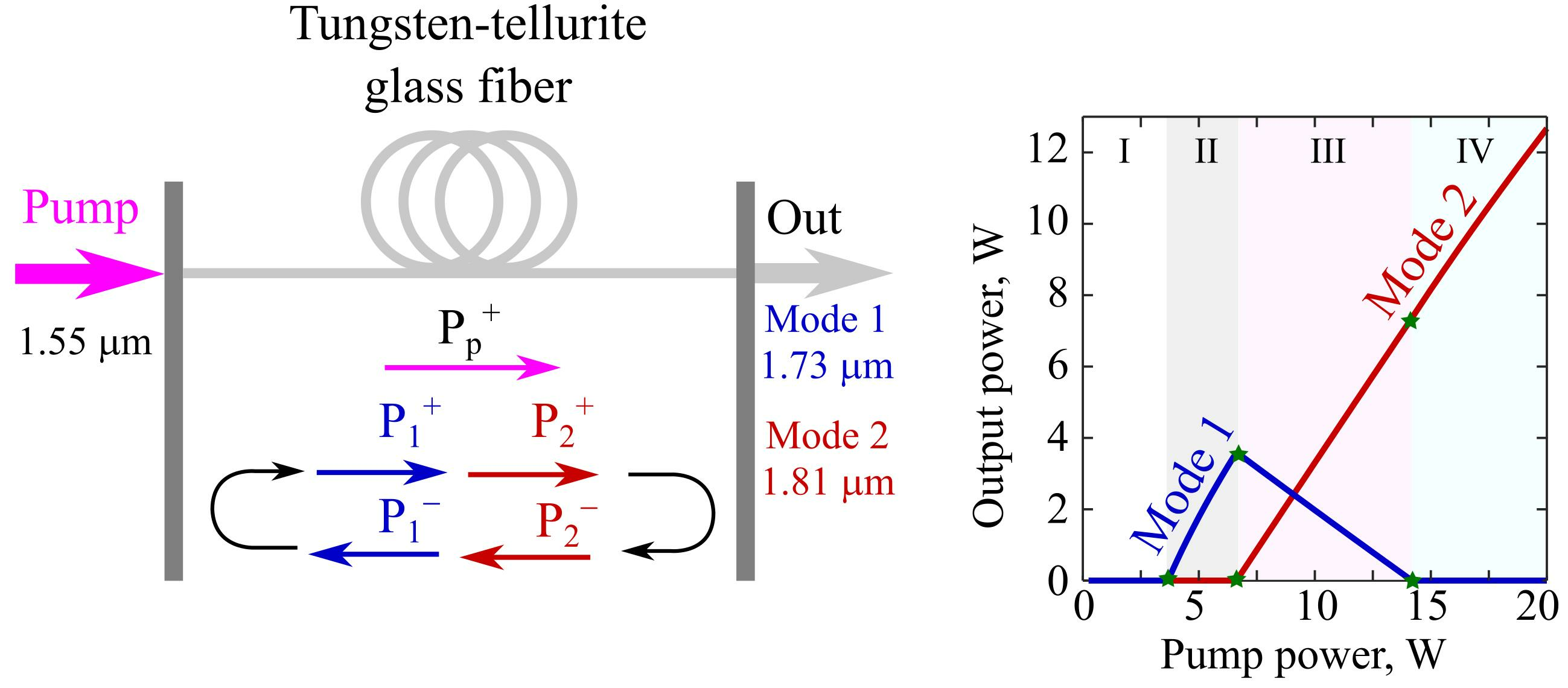
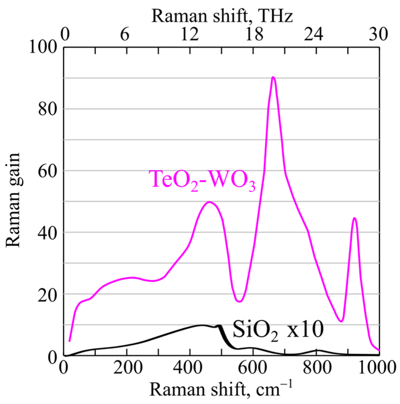
2.1. Conceptual Scheme
2.2. Numerical Model
3. Results
4. Discussion
5. Conclusions
Author Contributions
Funding
Data Availability Statement
Conflicts of Interest
References
- Li, C.; Shi, J.; Gong, X.; Kong, C.; Luo, Z.; Song, L.; Wong, K.K.Y. 1.7 μm wavelength tunable gain-switched fiber laser and its application to spectroscopic photoacoustic imaging. Opt. Lett. 2018, 43, 5849–5852. [Google Scholar] [CrossRef] [PubMed]
- Li, C.; Shi, J.; Wang, X.; Wang, B.; Gong, X.; Song, L.; Wong, K.K.-Y. High-energy all-fiber gain-switched thulium-doped fiber laser for volumetric photoacoustic imaging of lipids. Photon Res. 2020, 8, 160–164. [Google Scholar] [CrossRef]
- Kawagoe, H.; Ishida, S.; Aramaki, M.; Sakakibara, Y.; Omoda, E.; Kataura, H.; Nishizawa, N. Development of a high power supercontinuum source in the 1.7 μm wavelength region for highly penetrative ultrahigh-resolution optical coherence tomography. Biomed. Opt. Express 2014, 5, 932–943. [Google Scholar] [CrossRef] [PubMed]
- Chambers, P.; Austin, E.A.D.; Dakin, J.P. Theoretical Analysis of a Methane Gas Detection System, Using the Complementary Source Modulation Method of Correlation Spectroscopy. Meas. Sci. Technol. 2004, 15, 1629–1636. [Google Scholar] [CrossRef]
- Sugioka, K.; Cheng, Y. Ultrafast lasers—Reliable tools for advanced materials processing. Light Sci. Appl. 2014, 3, e149. [Google Scholar] [CrossRef]
- Zhang, J.; Fu, S.; Sheng, Q.; Zhang, L.; Shi, W.; Yao, J. Recent Progress on Power Scaling and Single-Frequency Operation of 1.7-µm Thulium-Doped Fiber Lasers. Opt. Laser Technol. 2023, 158, 108882. [Google Scholar] [CrossRef]
- Szewczyk, O.; Łaszczych, Z.; Soboń, G. Spectral Compression and Amplification of Ultrashort Pulses Tunable in the 1650–1900 nm Wavelength Range. Opt. Laser Technol. 2023, 164, 109465. [Google Scholar] [CrossRef]
- Firstov, S.V.; Alyshev, S.V.; Riumkin, K.E.; Melkumov, M.A.; Medvedkov, O.I.; Dianov, E.M. Watt-Level, Continuous-Wave Bismuth-Doped All-Fiber Laser Operating at 1.7 µm. Opt. Lett. 2015, 40, 4360–4363. [Google Scholar] [CrossRef]
- Thipparapu, N.K.; Wang, Y.; Wang, S.; Umnikov, A.A.; Barua, P.; Sahu, J.K. Bi-doped fiber amplifiers and lasers [Invited]. Opt. Mater. Express 2019, 9, 2446–2465. [Google Scholar] [CrossRef]
- Lee, J.H.; Howe, J.; Xu, C.; Liu, X. Soliton Self-Frequency Shift: Experimental Demonstrations and Applications. IEEE J. Sel. Top. Quantum Electron. 2008, 14, 713–723. [Google Scholar] [CrossRef]
- Zolotovskii, I.O.; Korobko, D.A.; Okhotnikov, O.G.; Stolyarov, D.A.; Sysolyatin, A.A. Generation of a broad IR spectrum and N-soliton compression in a longitudinally inhomogeneous dispersion-shifted fibre. Quantum Electron. 2015, 45, 844–852. [Google Scholar] [CrossRef]
- Zhang, Y.; Song, J.; Ye, J.; Xu, J.; Yao, T.; Zhou, P. Tunable Random Raman Fiber Laser at 1.7 µm Region with High Spectral Purity. Opt. Express 2019, 27, 28800–28807. [Google Scholar] [CrossRef]
- Zheng, P.; Wu, D.; Dai, S. Wavelength Tunable Raman Fiber Laser Based on Raman Gain Spectrum Control. Opt. Laser Technol. 2023, 164, 109496. [Google Scholar] [CrossRef]
- Pei, W.; Li, H.; Huang, W.; Wang, M.; Wang, Z. All-Fiber Tunable Pulsed 1.7 μm Fiber Lasers Based on Stimulated Raman Scattering of Hydrogen Molecules in Hollow-Core Fibers. Molecules 2021, 26, 4561. [Google Scholar] [CrossRef] [PubMed]
- Andrianov, A.V.; Anashkina, E.A. Tunable Raman lasing in an As2S3 chalcogenide glass microsphere. Opt. Express 2021, 29, 5580–5587. [Google Scholar] [CrossRef] [PubMed]
- Supradeepa, V.R.; Feng, Y.; Nicholson, J.W. Raman Fiber Lasers. J. Opt. 2017, 19, 023001. [Google Scholar] [CrossRef]
- Kharenko, D.S.; Gervaziev, M.D.; Kuznetsov, A.G.; Podivilov, E.V.; Wabnitz, S.; Babin, S.A. Mode-Resolved Analysis of Pump and Stokes Beams in LD-Pumped GRIN Fiber Raman Lasers. Opt. Lett. 2022, 47, 1222–1225. [Google Scholar] [CrossRef]
- Kuznetsov, A.G.; Nemov, I.N.; Wolf, A.A.; Evmenova, E.A.; Kablukov, S.I.; Babin, S.A. Cascaded Generation in Multimode Diode-Pumped Graded-Index Fiber Raman Lasers. Photonics 2021, 8, 447. [Google Scholar] [CrossRef]
- Qin, G.; Liao, M.; Suzuki, T.; Mori, A.; Ohishi, Y. Widely Tunable Ring-Cavity Tellurite Fiber Raman Laser. Opt. Lett. 2008, 33, 2014–2016. [Google Scholar] [CrossRef]
- Plotnichenko, V.G.; Sokolov, V.O.; Koltashev, V.V.; Dianov, E.M.; Grishin, I.A.; Churbanov, M.F. Raman Band Intensities of Tellurite Glasses. Opt. Lett. 2005, 30, 1156–1158. [Google Scholar] [CrossRef]
- Cheng, T.; Gao, W.; Xue, X.; Suzuki, T.; Ohishi, Y. Experimental Investigation of Multiple Raman Peak Properties in a Hundred-Meter Tellurite Fiber. Opt. Mater. Express 2016, 6, 3438–3445. [Google Scholar] [CrossRef]
- Okhrimchuk, A.G.; Yatsenko, Y.P.; Smayev, M.P.; Koltashev, V.V.; Dorofeev, V.V. Nonlinear Properties of the Depressed Cladding Single Mode TeO2-WO3-Bi2O3 Channel Waveguide Fabricated by Direct Laser Writing. Opt. Mater. Express 2018, 8, 3424–3437. [Google Scholar] [CrossRef]
- Zhu, G.; Geng, L.; Zhu, X.; Li, L.; Chen, Q.; Norwood, R.A.; Manzur, T.; Peyghambarian, N. Towards Ten-Watt-Level 3–5 µm Raman Lasers Using Tellurite Fiber. Opt. Express 2015, 23, 7559–7573. [Google Scholar] [CrossRef]
- Ni, C.; Gao, W.; Chen, X.; Chen, L.; Zhou, Y.; Zhang, W.; Hu, J.; Liao, M.; Suzuki, T.; Ohishi, Y. Theoretical Investigation on Mid-Infrared Cascaded Raman Fiber Laser Based on Tellurite Fiber. Appl. Opt. 2017, 56, 9171–9178. [Google Scholar] [CrossRef] [PubMed]
- Sorokin, A.A.; Leuchs, G.; Corney, J.F.; Kalinin, N.A.; Anashkina, E.A.; Andrianov, A.V. Towards Quantum Noise Squeezing for 2-Micron Light with Tellurite and Chalcogenide Fibers with Large Kerr Nonlinearity. Mathematics 2022, 10, 3477. [Google Scholar] [CrossRef]
- Agrawal, G.P. Nonlinear Fiber Optics, 6th ed.; Elsevier: Amsterdam, The Netherlands, 2019. [Google Scholar]
- Dianov, E.M.; Mashinsky, V.M. Germania-Based Core Optical Fibers. J. Light. Technol. 2005, 23, 3500–3508. [Google Scholar] [CrossRef]
- Li, W.; Seal, S.; Rivero, C.; Lopez, C.; Richardson, K.; Pope, A.; Schulte, A.; Myneni, S.; Jain, H.; Antoine, K.; et al. Role of S/Se Ratio in Chemical Bonding of As–S–Se Glasses Investigated by Raman, x-Ray Photoelectron, and Extended x-Ray Absorption Fine Structure Spectroscopies. J. Appl. Phys. 2005, 98, 053503. [Google Scholar] [CrossRef]
- Anashkina, E.A.; Andrianov, A.V. Switchable Cascade Raman Lasing in a Tellurite Glass Microresonator. ACS Photonics 2023, 10, 1485–1494. [Google Scholar] [CrossRef]
- Jackson, S.D.; Muir, P.H. Theory and Numerical Simulation of Nth-Order Cascaded Raman Fiber Lasers. J. Opt. Soc. Am. B 2001, 18, 1297–1306. [Google Scholar] [CrossRef]
- Svelto, O.; Hanna, D.C. Principles of Lasers; Springer: New York, NY, USA, 2010. [Google Scholar]
- Cai, Y.; Ding, J.; Bai, Z.; Qi, Y.; Wang, Y.; Lu, Z. Recent Progress in Yellow Laser: Principles, Status and Perspectives. Opt. Laser Technol. 2022, 152, 108113. [Google Scholar] [CrossRef]


| Parameter | Symbol | Value |
|---|---|---|
| Fiber core diameter | d | 6 µm |
| Numerical aperture (core/cladding) | NA | 0.18 |
| Pump frequency (λp = 1550 nm) | fp | 193.5 THz |
| Frequency of mode 1 (λ1 = 1727 nm) | f1 | 173.75 THz |
| Frequency of mode 2 (λ2 = 1807 nm) | f2 | 166.0 THz |
| Effective area at λp = 1550 nm | Aeffp | 39 µm2 |
| Effective mode area at λ1 = 1727 nm | Aeff1 | 47 µm2 |
| Effective mode area at λ2 = 1807 nm | Aeff2 | 51 µm2 |
| Raman gain (for mode 1 amplified by pump wave) | gp1 | 13.5 × 10⁻⁴ (W cm)−1 |
| Raman gain (for mode 2 amplified by pump wave) | gp2 | 6.3 × 10⁻⁴ (W cm)−1 |
| Raman gain (for mode 2 amplified by mode 1) | g12 | 2.8 × 10⁻⁴ (W cm)−1 |
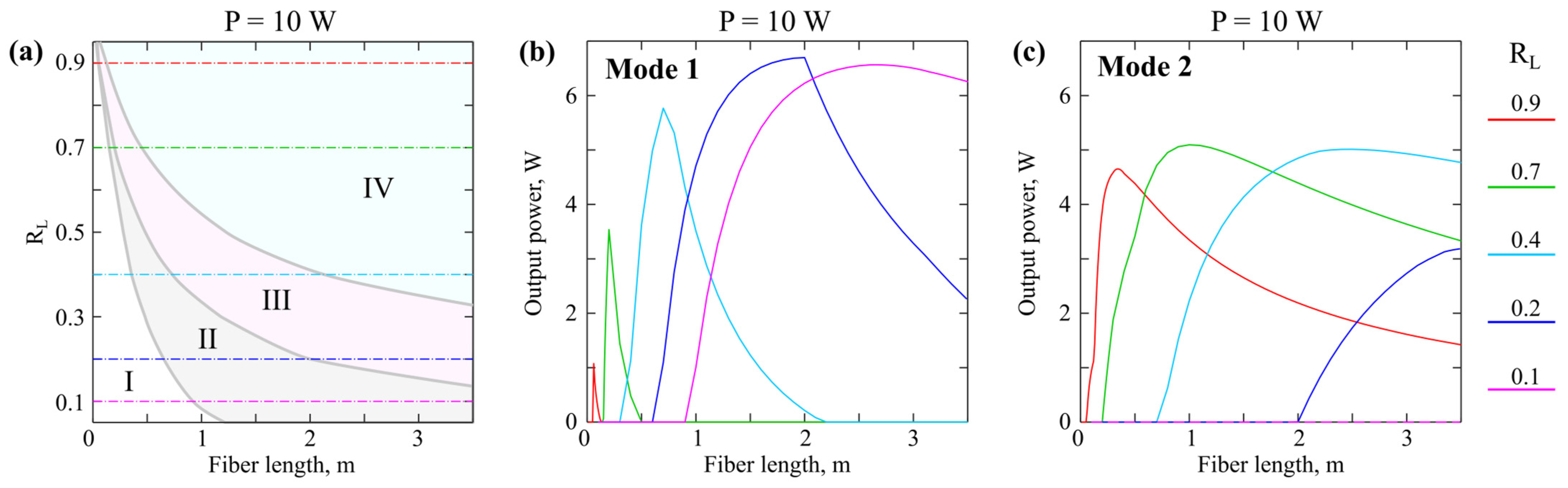
| Fiber loss | α | 0.3 dB/m (for Figure 3, Figure 4 and Figure 5); 0…3 dB/m (only for Figure 6) |
| Reflection coefficient for mode 1,2 at z = 0 | R01,02 | 0.98 |
| Reflection coefficient for mode 1,2 at z = L | RL1,L2 | 0.05…0.95 |
Disclaimer/Publisher’s Note: The statements, opinions and data contained in all publications are solely those of the individual author(s) and contributor(s) and not of MDPI and/or the editor(s). MDPI and/or the editor(s) disclaim responsibility for any injury to people or property resulting from any ideas, methods, instructions or products referred to in the content. |
© 2023 by the authors. Licensee MDPI, Basel, Switzerland. This article is an open access article distributed under the terms and conditions of the Creative Commons Attribution (CC BY) license (https://creativecommons.org/licenses/by/4.0/).
Share and Cite
Anashkina, E.A.; Andrianov, A.V. Numerical Analysis of Dual-Wavelength Tungsten-Tellurite Fiber Raman Lasers with Controllable Mode Switching. Fibers 2023, 11, 84. https://doi.org/10.3390/fib11100084
Anashkina EA, Andrianov AV. Numerical Analysis of Dual-Wavelength Tungsten-Tellurite Fiber Raman Lasers with Controllable Mode Switching. Fibers. 2023; 11(10):84. https://doi.org/10.3390/fib11100084
Chicago/Turabian StyleAnashkina, Elena A., and Alexey V. Andrianov. 2023. "Numerical Analysis of Dual-Wavelength Tungsten-Tellurite Fiber Raman Lasers with Controllable Mode Switching" Fibers 11, no. 10: 84. https://doi.org/10.3390/fib11100084