Article

Influence of Different Surfactants on Carbon Fiber Dispersion and the Mechanical Performance of Smart Piezoresistive Cementitious Composites

by
Athanasia K. Thomoglou
*,
Maria G. Falara
,
Fani I. Gkountakou
,
Anaxagoras Elenas
and
Constantin E. Chalioris
Department of Civil Engineering, Faculty of Engineering, Democritus University of Thrace (D.U.T.), 67100 Xanthi, Greece
*
Author to whom correspondence should be addressed.
Fibers 2022, 10(6), 49; https://doi.org/10.3390/fib10060049
Submission received: 23 April 2022 / Revised: 24 May 2022 / Accepted: 27 May 2022 / Published: 31 May 2022

Abstract

:
This experimental study presents the effect of different surfactants on micro-scale carbon fiber (CFs) distribution into carbon fiber reinforced cement-based composites (CFRC) in terms of flexural and compressive strength, stiffness, flexural toughness, and strain-sensing ability. Conducting a narrative review of the literature focusing on the fibers’ separation, this paper follows a methodology introducing a combination of mechanical and chemical carbon fibers dispersion, as well as the different mixing processes (wet or dry). Three types of surfactants: Carboxymethyl cellulose (CMC), cellulose nanocrystal (CNC), and superplasticizer (SP), were applied to evaluate the CFs distribution in the cement paste matrix. Compressive and flexural strength, modulus of elasticity, and ductility of the cement-based composites (CFRC) reinforced with 0.5 wt.% CFs were investigated by three-point bending and compressive tests; flexure tests were also conducted on notched 20 × 20 × 80 mm specimens using the Linear Elastic Fracture Mechanics (L.E.F.M.) theory. Moreover, the electrical conductivity and the piezoresistive response were determined by conducting electrical resistance measurements and applying compressive loading simultaneously. The results clearly reveal that the CFs/SP solution or the CFs’ dry incorporation led to a significant enhancement of flexural strength by 32% and 23.7%, modulus of elasticity by 30% and 20%, and stress-sensing ability by 20.2% and 18.2%, respectively. Although the wet mixing method exhibits improved mechanical and electrical conductivity performance, constituting an adequate strain and crack sensor, the authors propose dry mixing as the most economical method, in addition to the enhanced mechanical and electrical responses. The authors recommend an effective method for structural health monitoring systems combining an economical CFs insertion in cementitious smart sensors with great mechanical and self-sensing responses.

1. Introduction

During recent decades, fiber-reinforced cement-based materials have gained popularity in the building industry, mainly to enhance plain concrete’s ductility, flexural toughness, and flexural strength, providing multi functionalities for novel construction applications. Using fibers to reinforce the quasi-brittle cementitious materials is frequently used as innovative civil engineering materials, resulting in multiscale property changes ranging from subtle to substantial depending on the fibers’ dispersibility [1,2,3,4,5,6,7]. Carbon fibers (CFs) with lengths ranging from millimeters to one-centimeter exhibit superior mechanical properties [8,9]. The use of CFs in cement-based matrices results in composites with exceptional flexural toughness, high modulus of Elasticity (E), lightweight, outstanding conductivity, and corrosion resistance [10,11].
According to the narrative review, the literature focuses on the principal issue of fibers’ dispersion. The proposed recommendation to solve this problem is either the physical (or mechanical) or chemical separation of the fibers. The methodology of this research introduces the combination of the two major key factors (mechanical and chemical), as well as the different mixing processes (wet or dry). The aim of this research is to define the dispersion effect of CFs on mechanical properties and electrical conductivity. As received, CFs often suffer from agglomerates [8,12]. Because of the hydrophobic surface of chopped CFs in cementitious specimens, the uniform dispersion of them is a difficult process. However, the critical parameter of the hydrophobicity of CFs should be taken into account as it significantly blocks their dispersion in the cementitious matrix [13,14]. Moreover, the porosity of the matrix is increased by the fiber entanglement, which causes the deterioration of the mechanical and electrical properties of carbon fiber-reinforced cement-based composite materials (CFRC) [15,16,17,18]. Furthermore, the existence of covalent non-planar C-C bonds at their surface leads to exceptional electrical properties [19,20]. Several researchers have proved that homogenized CFs are necessary for CFs application and the efficiency of the fibers [1,15,21]. Thus, the structural integrity is under threat from fiber-free areas, where cracks are more probable to expand. Whereas other researchers [22,23,24] have attempted a different procedure to determine damage at the first cracking stages of concrete beams using the admittance values of embedded and surface-attached PZTs through a non-portable EMI monitoring system.
The hydrophilicity can be avoided by a surface treatment before the integration of the fibers in the cement matrix [25,26]. In addition, the admixtures that can be used along with the fibers have an effect on the dispersion of fibers. In order to improve the dispersion and hence the cement strength, the dispersant can be used to enhance the reinforcing function of the CFs. However, the dispersant applied as a surfactant causes more bubbles to form in the composites, resulting in the deterioration of the surface tension of the fibers and the surface energy of the paste. The application of surfactants for the processing of CFs is limited. Giraud et al. [27] used sodium dodecyl sulfate (SDS) and benzalkonium chloride as surfactants in applying a thermoplastic sizing to unsized polyacrylonitrile CFs, and the results revealed that SDS significantly offered a homogenous film of sizing. Chuang et al. [11] dispersed polyacrylonitrile CFs using different cellulose derivatives. They concluded that the hydroxyethyl cellulose was superior to the others tested as it provided the best abundance of polar hydroxyl groups to form hydrogen bonds or to bridge with the polar groups on the surface of the CFs enhanced the dispersion.
All surfactants are not equally effective in changing droplet wettability. Subsequently, a range of surfactants mentioned in the bibliography, regularly used to disperse materials composed of carbon, have been studied to verify the most suitable for use in this regard. The aqueous solution with the anionic surfactant sodium dodecylbenzene sulphonates is found to be a good dispersion agent for CFs; the interfacial adhesion between fibers is not affected, leading to the optimum stability of the discontinuous fibers [19,28,29,30]. As an admixture, silica fume (SF) facilitated CFs dispersion and displayed an improvement in the interfacial interaction between the fibers and the Portland cement phases to improve material properties, particularly increasing the strength of cement-based material [3,9,13,27,29,30,31,32]. A typical silica fume content is 15% by the mass of cement [16,31,33,34,35,36,37,38,39], with the normal particle size around 0.1 mm helping the fibers break loose from one another as mixing arises [3,40]. What is more, it was observed that the inclusion of superplasticizer (SP) in the CFRC mixes enhanced the mobility and viscosity of the CFRC mixes, and the extent of the reduction in electrical resistance was better in SP-based CFRC containing SP, developing higher electrical conductivity, which resulted in the improvement of functional structural and non-structural properties of CFRC. The addition of SP in concrete significantly improves the bond of the CF cement matrix and helps in the deagglomeration of CFs [14,15,21,41]. Polymers such as latex particle dispersions can also be admixtures that contribute to the fiber–cement bond as well as the fiber dispersion [3,34,35,36,37]. Carboxymethyl cellulose (CMC) and nanocrystal cellulose (CNC) as surfactants, normally with the combination of silica fume, allow the dispersion of CFs in cement-based materials [17,18,25,34,36,38,42,43,44,45].
The use of CFs in different volume content has the potential to improve the flexural toughness with an enhancement in resistance to crack propagation [46,47]. It was investigated that the specimen consisting of 4% CFs produced the highest early-crack and ultimate flexural toughness at 28 days in contrast to the other mortars with lower incorporation of CFs [48]. This is due to the enhancement of the frictional bond of the fibers with the matrix. It was also demonstrated that the addition of 0.25% wt. CFs into cement paste enhanced the flexural toughness contrasted to the reference specimen and improved the mechanical properties as well as the ductility [49].
According to the literature, many methods based on linear elastic fracture mechanics (LEFM) have been examined in order to assess the toughening effect of quasi-brittle cement-based composites. Some information is available on the toughness indices of fiber-reinforced concrete obtained from the load versus crack mouth opening displacement (CMOD) curves of the LEFM experiments. The toughness measurements of steel-fiber reinforced concrete directed that the load–CMOD curves gave a better indication of the mechanical performance of cement-based materials and were more sensitive in recognizing the effectiveness of the fibers than load-mid deflection curves measured at relatively small deformations [50,51,52]. The limitations of standards and guidelines for evaluating the toughness of fiber-reinforced composite materials have been studied by [53,54,55].
As above-mentioned, many approaches were introduced to determine the extent of fiber dispersion. Nevertheless, it is not reliable to conclude exact results only using the above methods, and existing research seldom focus on the evaluation methods. In the subsequent sections, the different CFs mixing methods, which stand as the key parameters, the dispersive status of the fibers, and special experimental measurements are first portrayed. Afterward, a comprehensive analysis of the effect of the beneficial smart sensors’ amount added in the cement paste mass to give increased 28-day flexural and compressive strength, electrical conductivity, and flexural toughness to the micro-composite material is presented. The final section summarizes the conclusions. The concentration of 0.5 wt.% CFs, although it has been little investigated as a concentration in the international literature, in the present work, this concentration was considered as a basis due to the fact that in this content, we certainly expect a good dispersion as a constant parameter. Concluding with the best CFs’ type of incorporation into the matrix, the authors will continue with the investigation of the CFs’ amount distribution to find the optimum one. The current investigation is expected to contribute significantly to creating cementitious materials with enhanced mechanical performance and piezoresistive response.
The smartness of the micro-modified cement pastes and, therefore, the piezoresistive behavior, was attained by estimating the changes in the electrical resistance of the prismatic specimens when they were subjected to cyclic compressive loading in the elastic region or monotonic compressive loading up to failure [51]. The piezoresistive response of these prismatic specimens CF modified cement paste specimens, under monotonic compressive loading, was substantially enhanced just by adding a low amount of 0.5 wt.%. The results clearly demonstrate that the CF reinforcement beneficially modifies the structure of the cementitious matrix, providing the material with the ability to perform multiple structural functions, such as crack initiation and propagation and failure detection by recording the changes in its resistivity. This investigation analysis is expected to contribute significantly to the development of smart cementitious CFs materials with improved mechanical and electrical properties.

2. Materials and Methods

In this research, cement pastes reinforced with carbon fibers (CFs) were prepared with different mixing procedures (Figure 1a). The characteristic properties of the micro reinforcement appear in Table 1.
Type I Ordinary Portland Cement (OPC) 42.5 R provided by TITAN Hellas, known as common or general-purpose cement, was used according to ASTM 150 to create cement pastes. From the particle size distribution of CEM I 42.5, the average diameter is 16.5 μm. For the reinforcement, the carbon fibers tow supplied by Toray Composite Materials America, Inc. (CFs Toray T700, carbon purity: >93%, the filament diameter of CFs 7 μm, CFs’ length 5 mm) were used. The fiber was produced by the treatment of an acrylic fiber precursor, with pyrolysis, surface treatment, and sizing processes. The carbon fibers we used to conduct this research are already cut from a tow in 6 mm length micro-scale carbon fibers using an electrical fiber chopper. Some individual fibers remain with each other forming flakes of indefinite shape and size until they are mechanically or chemically separated. In order to prepare the CFRC samples, the authors followed two different methods to incorporate the CFs. In the first method, the wet mixing was conducted manually or mechanically by applying ultrasonic energy. Three types of surfactants, superplasticizer (SP), carboxymethyl cellulose (CMC), and cellulose nanocrystal (CNC) were applied to evaluate CFs’ dispersion in the cement paste specimens. Cellulose Nanocrystal (Nanocrystalline Cellulose, CNC) was used as a dispersant for the CFs to improve their incorporation into the cement paste. It was in a dry powder form, and its width and length varied between 10 and 20 mm and 300 and 900 mm, respectively. Carboxymethyl Cellulose (CMC) is also a surfactant that was used to enhance dispersion. It was applied as a white powder, and the values of its viscosity were approximately 700 to 10,000 MPa. Moreover, its water content was ≤10%, and the PH value ranged from 6.0 to 8.0. The three above-mentioned surfactants were dispersed in deionized water and stirred manually for 2 min with the CFs. The preparation of the aqueous/CFs solutions included the application of ultrasonic energy by a 500 W cup-horn high-intensity ultrasonic processor with a standard probe of 19 mm diameter at cycles of 20 s, while the temperature was controlled between 38 and 60 °C in order to avoid the solution’s overheating. The power of the ultrasonic wave was 500 W, but in the present process, only 47% of this power was applied, which means 235 W. After the sonication process was completed, the suspensions were added to the cement. In the second method, the dry mixing, the CFs were added to the matrix during the mixing process.
The mixing of the materials was performed according to the procedure outlined by ASTM 305 at the water to cement ratio of w/c = 0.485 using a standard robust mixer providing 140 ± 5 rpm (r/min). After mixing, the mixtures were cast in (a) 40 × 40 × 160 mm oiled steel molds for flexure and compressive tests, (b) 20 × 20 × 80 mm oiled steel molds where titanium meshes were embedded during the casting so as to record resistance values and determine the conductivity values, and (c) 20 × 20 × 80 mm oiled steel molds so as to determine the flexural toughness following the Linear Elastic Fracture Method (LEFM). After 24 h, the samples were demolded and cured at 22 °C room temperature and 100% humidity conditions until testing at 7, 14, and 28 days. A 6 mm notch was introduced into the specimens used to conduct LEFM using a band saw machine.

3. Experimental Section

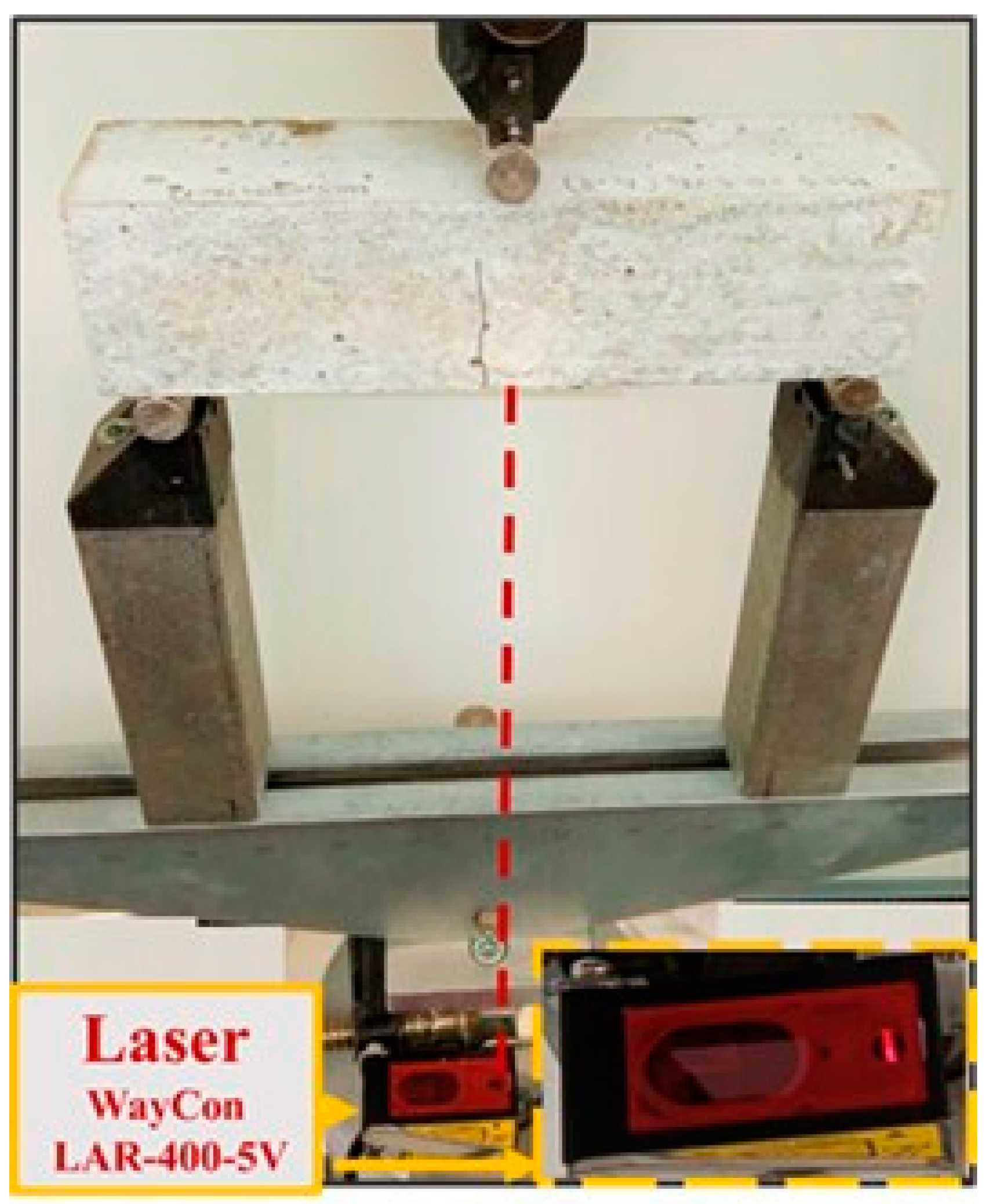
3.1. Mechanical Testing Procedure

Short CFs with a 6 mm length, as manufactured by Toray, are noted in Figure 1b and were used for attaining the electrical properties in the cement paste. A commercially available polycarboxylate-based surfactant Viscocrete Ultra 600, provided by Sika Hellas, with a specific density of 1.1 gr/cm3 and a pH value of 4.5–6.5 (at +20 °C). We added the Viscocrete Ultra 600 to deionized water to produce an aqueous solution, and we used it in this research as a surfactant. It was employed to contribute to the dispersion procedure of CFs. The properties of the short CFs are represented in Table 1. Type I OPC 42.5 R [56] was used as a binder. After the dispersion process, the mixing of the materials was performed according to the procedure defined by the ASTM C305-20 [38].
Three-point bending tests were performed to evaluate the flexural and compressive strength of the CFs reinforced pastes. The 40 × 40 × 160 mm prismatic specimens were tested in three-point bending at the age of 7, 14, and 28 days as shown in Figure 2. The tests were conducted with a 25 kN MTS servo-hydraulic, closed-loop testing machine under displacement controls. The rate of displacement remained at 0.1 mm/min. The deflection was measured using a laser meter (WayCon LAR-400-5V) to measure the vertical deformation of the specimen’s middle-length lower side. After the aforementioned process, the two halves of each prism were subjected to a compression test according to the ASTM C349. The test was carried out using a 2000 kN testing machine under force control. The rate of displacement was maintained at 0.5 N/min.
The flexural toughness of the micro-modified cement mixtures with water to cement proportion equal to w/c = 0.485, using CFs at an amount of 0.5 vol% of cement, was experimentally determined by notched 20 × 20 × 80 mm specimens following the LEFM theory; while the electrical properties by 2-pole AC resistivity measurements on the specimens by using titanium electrodes.

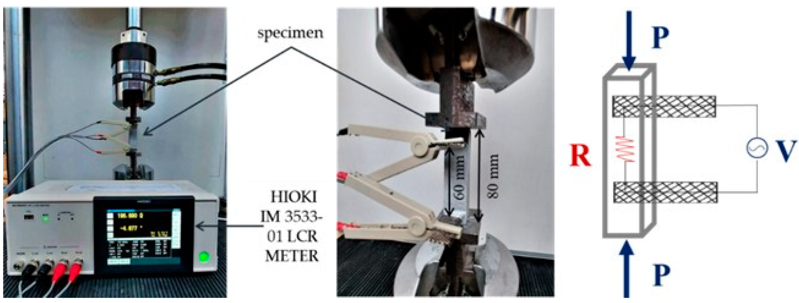
3.2. Self-Sensing Experimental Procedure

In addition to the enhanced mechanical behavior, the CF-reinforced materials are most well-known for their multifunctional behavior, which results from their electrical properties, including strain sensing and piezoresistive behavior. The electrical conductivity is mostly determined by the tunnel effect formed between overlapped CFs which are uniformly distributed in the cementitious matrix or between adjacent fibers.
In this work, the resistivity of the CF-reinforced cement specimens at the age of 28 days was investigated by the application of Alternating Current (AC) based on the 2-pole approach with two electrical contacts in the form of titanium electrodes being integrated into the matrix in two parallel planes, as illustrated in Figure 3. The electrical resistance was measured using a HIOKI IM 3533-01 LCR METER at a 100 kHz frequency [36]. The amplitude of the sinusoidal voltage was selected to be 2 V. In order to consider the nature and the geometry of the micro-composites, the electrical resistivity, ρ, replaced the resistance measurements estimated as resistance per unit length ρ = RS/L, where R represents the resistance of the micro-composite, S is the cross-section of the sample and L is the distance among the two inner electrodes. Conductivity is the inverse of the resistivity value.
In order to examine the strain sensing ability and the piezoresistive behavior of the cement paste composites at the age of 28 days, the aforementioned 2-pole approach was applied, whilst a hydraulic testing machine MTS with a 25 kN capacity was used for the simultaneous implementation of the specimen’s cyclic or monotonic uniaxial compressive loading. The cyclic compressive load of a maximum of 3 kN (load within the limits of the elastic region, that the value of the stress is approximately 7.5 MPa) was applied in each sample, with each cycle of loading–unloading lasting about 120 s, while the monotonic compressive loading was performed up to specimen’s failure with a loading rate of 0.005 mm/min. The values of load and resistance were recorded every 5 s. The test setup is represented in Figure 3.

4. Results

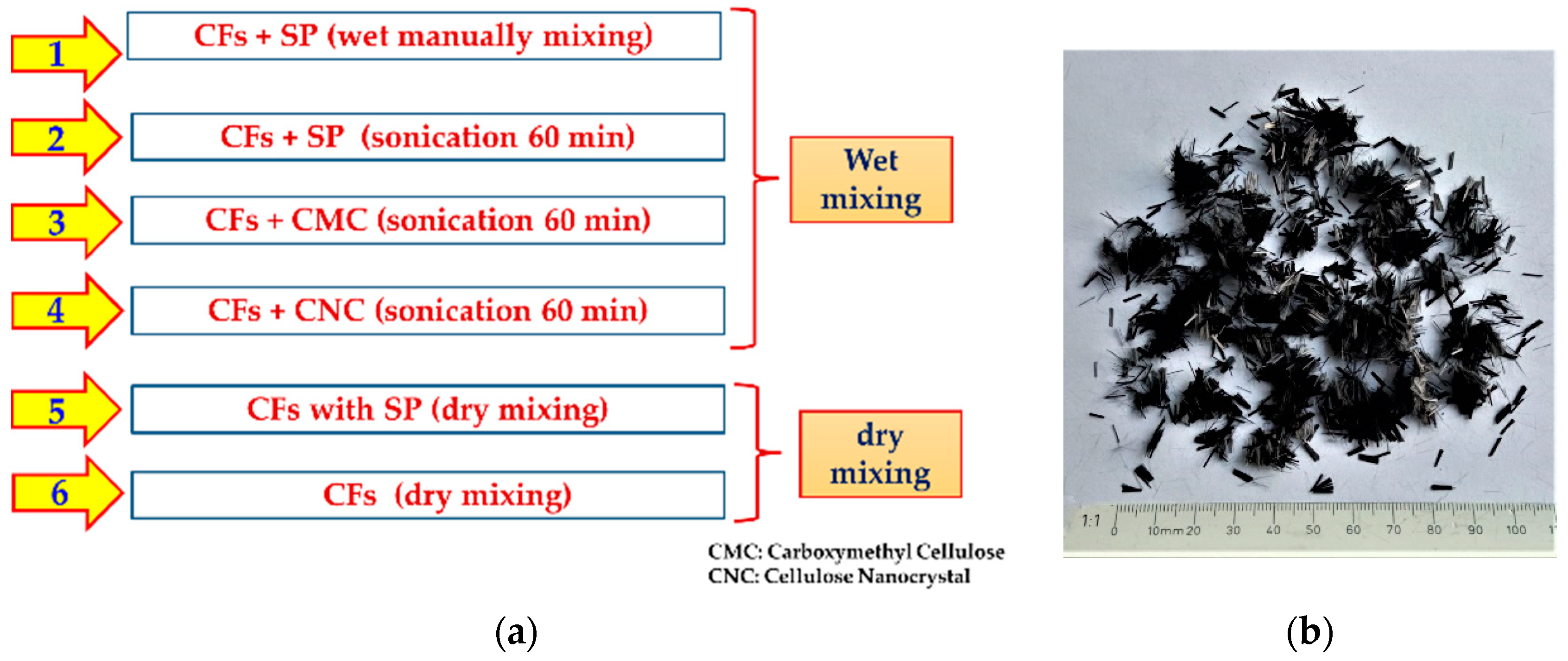
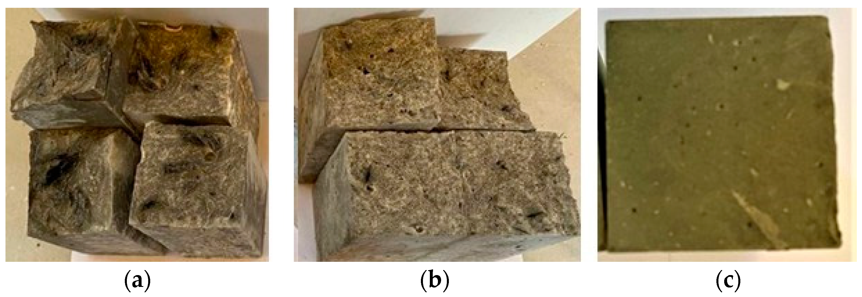
4.1. Dispersion of Microscale CFs

The dispersion can be enhanced by using surfactants as an admixture in the wet mixing (Figure 4a). In Figure 4a, the different wet CFs’ dispersant methods and their relative mixtures are depicted. Three types of surfactants (SP, CNC, and CMC) were used to achieve a uniform CFs’ dispersion in deionized water, as shown following either mechanical (manually of sonication) or chemical mixing. By visual observation, the CFs were more effectively separated from each other when they were dispersed in water containing superplasticizer (SP) by the wet mixing under the ultrasonic energy application, compared to the rest of the wet mixing methods. On the contrary, in the case of dry mixing, the addition of SP accomplished at the end of the mixing process diluted the mixture a lot, as observed in Figure 4b, and as a result, this deteriorated the mechanical response of the reinforced specimens compared to those without SP addition (see Figure 5 and Figure 6). Carbon micro-fibers were added to cement mixtures in the form of aqueous solutions at a concentration of 0.5 wt.% of cement. In Figure 5, it is presented that the 28-day compressive strength of cement composites increased by 31% in the dry mixing method of CFs with the cement by adding SP, while the dry mixing of CFs without SP followed with an increase of 24%, in contrast to the plain cement paste sample [2,6,10,34]. All of the other methods followed with lower rates, from a 22% increase in the case of simple mixing and SP addition to a 35% decrease in compressive strength with the addition of CMC. Wang et al. [8] investigated the effect of CF incorporation into the cementitious matrix at low amounts of 0.2–0.8 wt.% by cement. They demonstrated an increase in compressive strength by 20%, and the tensile strength was 2.4 times that of the 26.8% enhanced modulus of elasticity compared to the material without the reinforcement.
The 7th, 14th, and 28th-day compressive strength of the carbon microfiber specimens with the different surfactants is depicted in the diagram in Figure 5. The addition of microfibers resulted in an insignificant improvement in compressive strength for 0.5 wt.%, depending to a small extent on the carbon microfiber content. The 28-day, microfiber-reinforced specimens showed the largest compressive strength enhancement, 10.4%, with the method of dry mixing without SP, while with the wet method of SP addition and simple agitation with a manual stirrer by 8.6%. The method using the dry mixing method, adding SP, followed by 5%. The aforementioned mechanical performance exhibited by the 0.5 wt.% CF-reinforced composite may be attributed to the insufficient dispersion of carbon micro-fibers over the cementitious matrix.
Figure 6 presents the flexural strength results of all mixtures at the hydration age of 28 days. Ιt is observed that most composite cement pastes show greater 28-day flexure strength in comparison to the reference material (plain cement specimen).
In particular, the reinforced cement paste with carbon microfibers in an amount of 0.5 wt.% of cement shows an increasing tendency in flexure strength by 32% with the wet method of adding SP using 60 min sonication and with the dry mixing without SP by 24%. The specimens reinforced with the other methods show lower growth rates, while the method of dispersing the carbon microfibers with the CNC solvent leads to a deterioration in flexural strength. This is probably due to the insufficient dispersion of CFs due to their very large number, resulting in the formation of agglomerates. This enhancement of the flexural strength by adding short CFs was expected. Similar values have already been demonstrated by other researchers for CFs cement-based reinforced pastes [57,58,59]. Hambach et al. [58] reported that the addition of a small amount of CFs, 1% (by vol.), led to an outstanding increase in flexure by 146% compared to plain cement paste.
Similar behavior to flexural capacity is demonstrated by Young’s Modulus (Figure 7), the values of which were indicated experimentally within the elastic limit of load-deflection attained by the three-point bending approach in Figure 7.
From the test results presented in Figure 7, it is deduced that the modulus of elasticity increases from 20% to 30% under the different mixing methods of CFs. Specifically, the concentration of 0.05 wt.% of cement, respectively, decreases by 26% for the 0.5 wt.% of cement regarding the control specimens. This is associated with the effective dispersion of CFs in the cementitious matrix for 0.5 wt.% of cement. Contrariwise, a good separation was not accomplished for the case of CMC and CNC addition, showing a negative impact on the strength. Moreover, the insufficient dispersion seems to be the reason that this is accountable for the low degree of the modulus of elasticity [35,42].

4.2. Self-Sensing Response of Micro Modified Cement Pastes

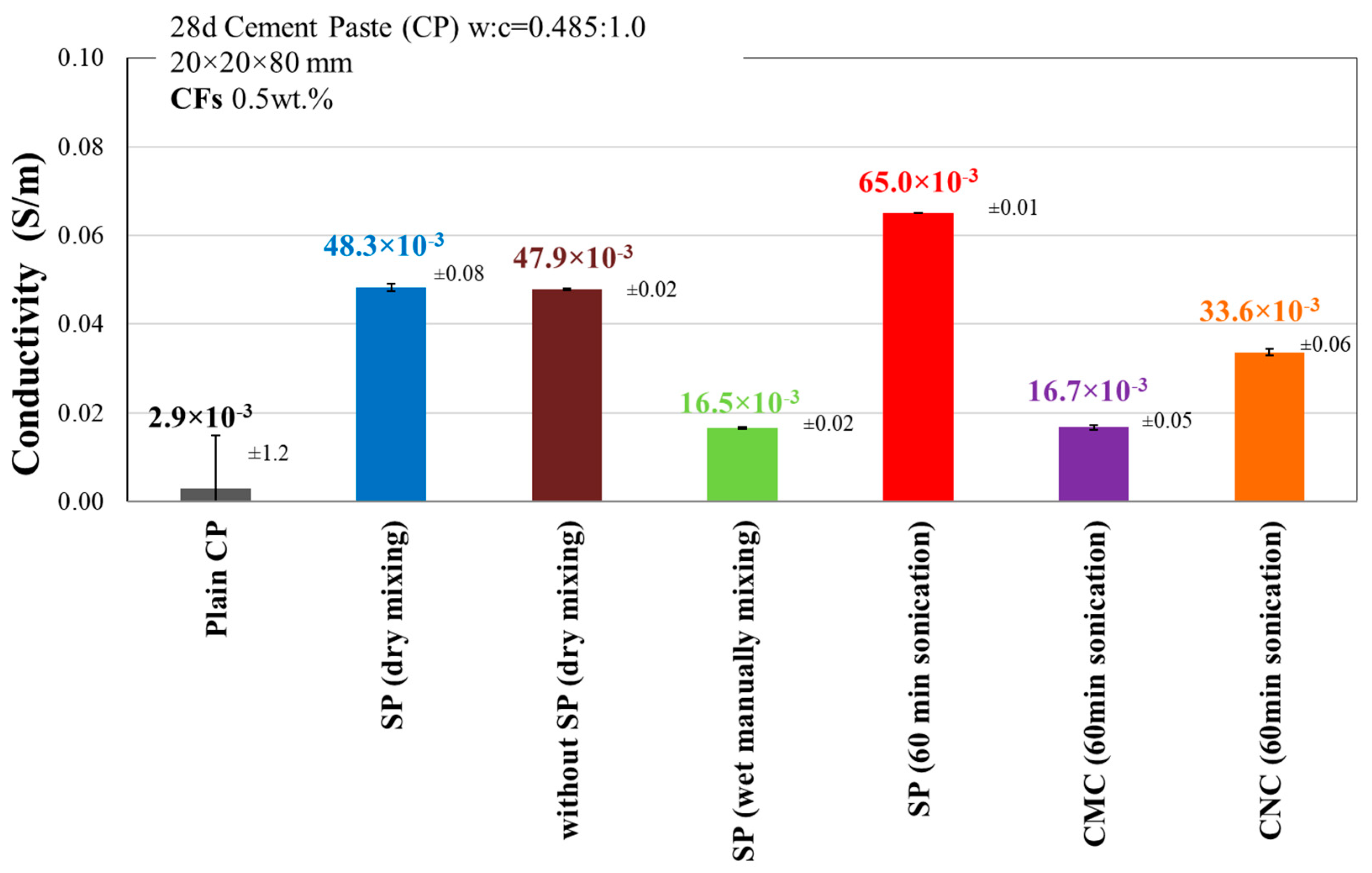
4.2.1. Electrical Conductivity Properties

The average conductivity measurements derived from the experimental resistance measurements of the 28-day plain and reinforced cement pastes with CFs at volume fractions of 0.5 wt.% are presented in Figure 8. The addition of CFs incorporated by dry mixing resulted in an almost 17 times higher conductivity value compared to plain cement paste. An even higher increase in conductivity, by 96%, is achieved in the case of introducing the CFs dispersed by the ultrasonication process. This can be attributed to the adequate distribution of CFs in the cement-paste matrix, resulting in a continuous electrical network that allows the current to pass more easily.
It is obvious that the combination of high conductive CFs, along with their uniform distribution in the matrix using the most appropriate incorporation method, allowed the formation of a continuous conductive network, significantly increasing this way the micro composites’ electrical conductivity by one order of magnitude. Low conductivity values may be attributed to the existence of agglomerates, implying a discontinuous CFs’ network formation.
As a result, an insufficient dispersion of CFs led to the presence of agglomerates in the cement paste matrix, which in turn degraded the composite’s electrical as well as affected flexural strength, stiffness, and compression.

4.2.2. Self-Sensing Ability of CF Modified Cement Pastes

The determination of the self-sensing ability and crack detection of micro-scale CFRC pastes took place through the fractional changes in electrical resistance, known as piezoresistivity measurements, under the coincidental application of a uniaxial compressive load either cyclically in the elastic region or monotonically up to failure. The average change (Δρ/ρ0) is obtained by dividing the difference in values of resistivity each time and initial resistivity, Δρ, by the value of the initial resistivity, ρ0. During the application of cyclic compressive loading, the resistivity gradually decreases during loading while increasing during unloading, also showing that the load levels were within the elastic region of the composites and did not cause permanent damage within the reinforced specimens. Figure 9 presents the piezoresistive behavior of 20 × 20 × 80 mm cement paste specimens enhanced with CFs at a volume fraction of 0.5% of cement, respectively, which were subjected to cyclic compressive loading within the elastic region (0–8 MPa).
In Figure 9, the electrical resistivity changes in the conductive cement paste composites in various situations are represented. It is demonstrated that the electrical signal and piezoresistivity could be useful parameters to assess the formation of cracks, traffic monitoring, stress/strain intensity, flexural failure of the concrete beam, and also the natural frequencies identification of constructions during the vibration process. The electrical resistivity and the average change in resistivity for all of the specimens are represented in Table 2.
In view of the similarity in the piezoresistive effect curves of the specimens by the different mixing methods, the piezoresistive curves of the CF-reinforced specimens with added SP and sonication and with dry mixing present an optimistic piezoresistive response.
The CF-reinforced cement pastes exhibited an improved strain sensing response when the CFs were added either when they were separated in a water solution under the application of ultrasonic energy or when they were incorporated by dry mixing. Specifically, the micro-scale CFs incorporated into the cement paste and dispersed by sonication yielded the highest conductivity, 65.0 × 10⁻³ S·m−1, and a greater average change in resistivity, 20.2%, compared to neat cement paste. Significantly, the dry mixing method without SP appears to have similar behavior with a conductivity, 47.9·10−3 S·m−1 (Figure 9 and Table 2), and an average change in resistivity, 18.5%, compared to plain cementitious specimens. This statement is according to the previous results of the piezoresistive behavior of specimens reinforced with CFs as investigated by Azhari and Banthia [59].
In conclusion, if we consider that it is the most economical method of the two mentioned above, the specimen with dry mixing has better piezoresistive performance and better linear variation of sensitivity. The self-sensing behavior of CF reinforced cement pastes up to the failure is presented in Figure 10.
For more study of the effect of the incorporation CF on the self-sensing and crack detection ability of the reinforced cement pastes, additional piezoresistivity experiments were conducted, with the simultaneous application of monotonic compressive loading up to failure. At first glance of the combination of stress–strain and average change in resistivity–strain curves (Figure 9 and Figure 10), all of the reinforced specimens exhibited a great ability to perceive the change in the applied stresses, the induced mechanical deformation, and the formation of the cracks. Therefore, they can be considered piezoresistive sensors.
More specifically, the CFs sensors in the case of the dry mixing method, which exhibit the optimum average change in resistivity under cyclic loading, demonstrate a very good decrease in the average change in resistivity by almost 15.7% and up to 90% of the maximum compressive load (normalized stress is 0.91). In the case of CFs added in the form of an aqueous solution under the application of ultrasonic energy, the average change in resistivity changes by almost 8.8% up to total failure, and in the case of CFs wet mixing with the addition of SP, the average change in resistivity changes by 13.7% up to 93% of the maximum compressive load, indicating the sensor’s ability to detect the applied load. In all cases, at the post-crack stage, the average change in resistivity starts to increase, implying the increase in resistance value indicating that the material turned out to be less reactive to the applied load and its mechanical deformation, and finally, the piezoresistivity response started to flatten as there is practically no change in resistivity up to total failure.

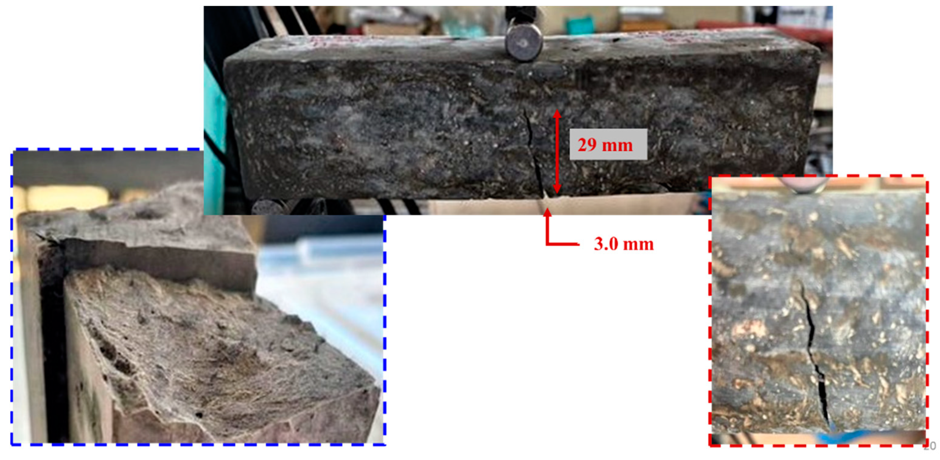
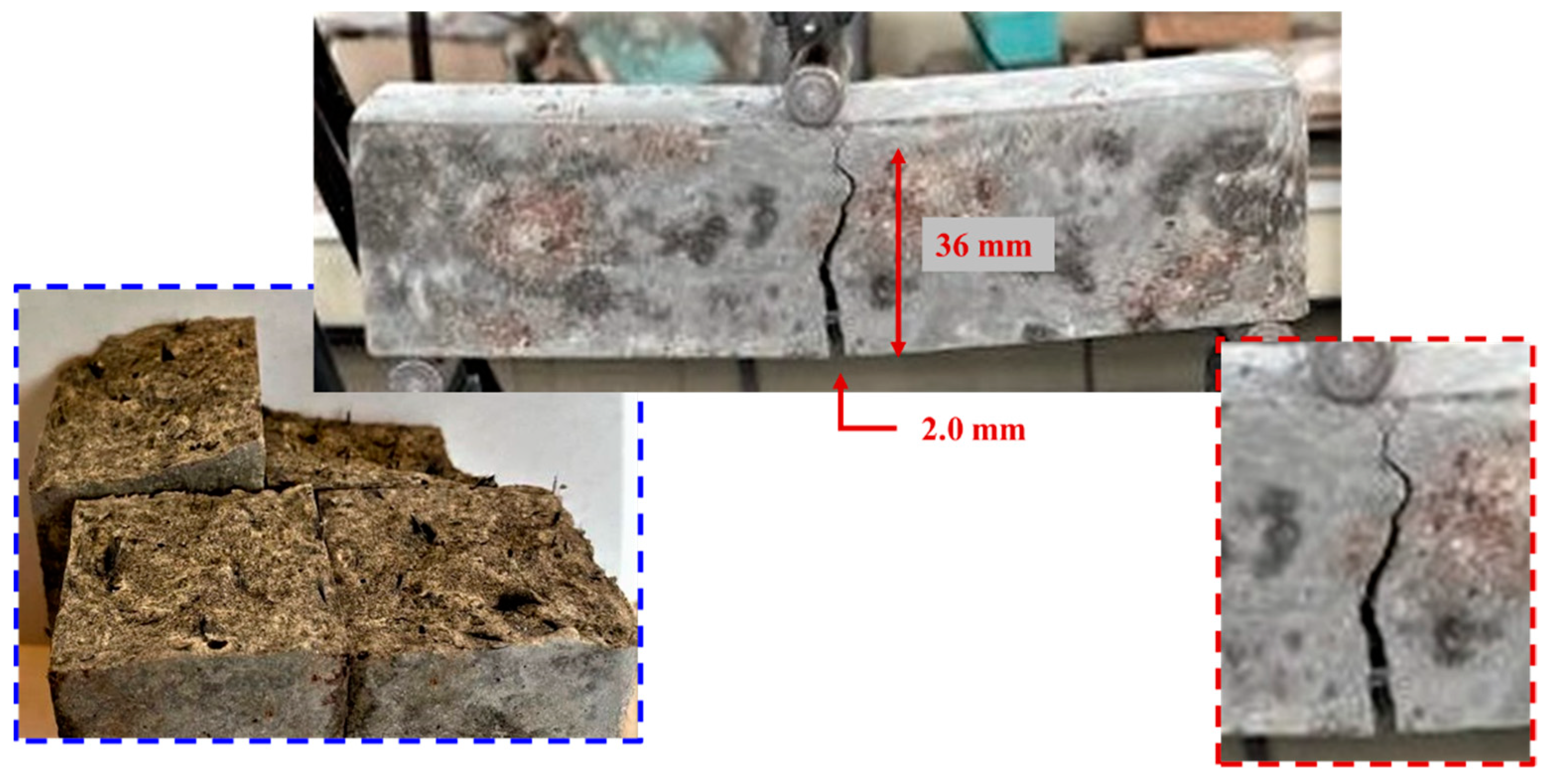
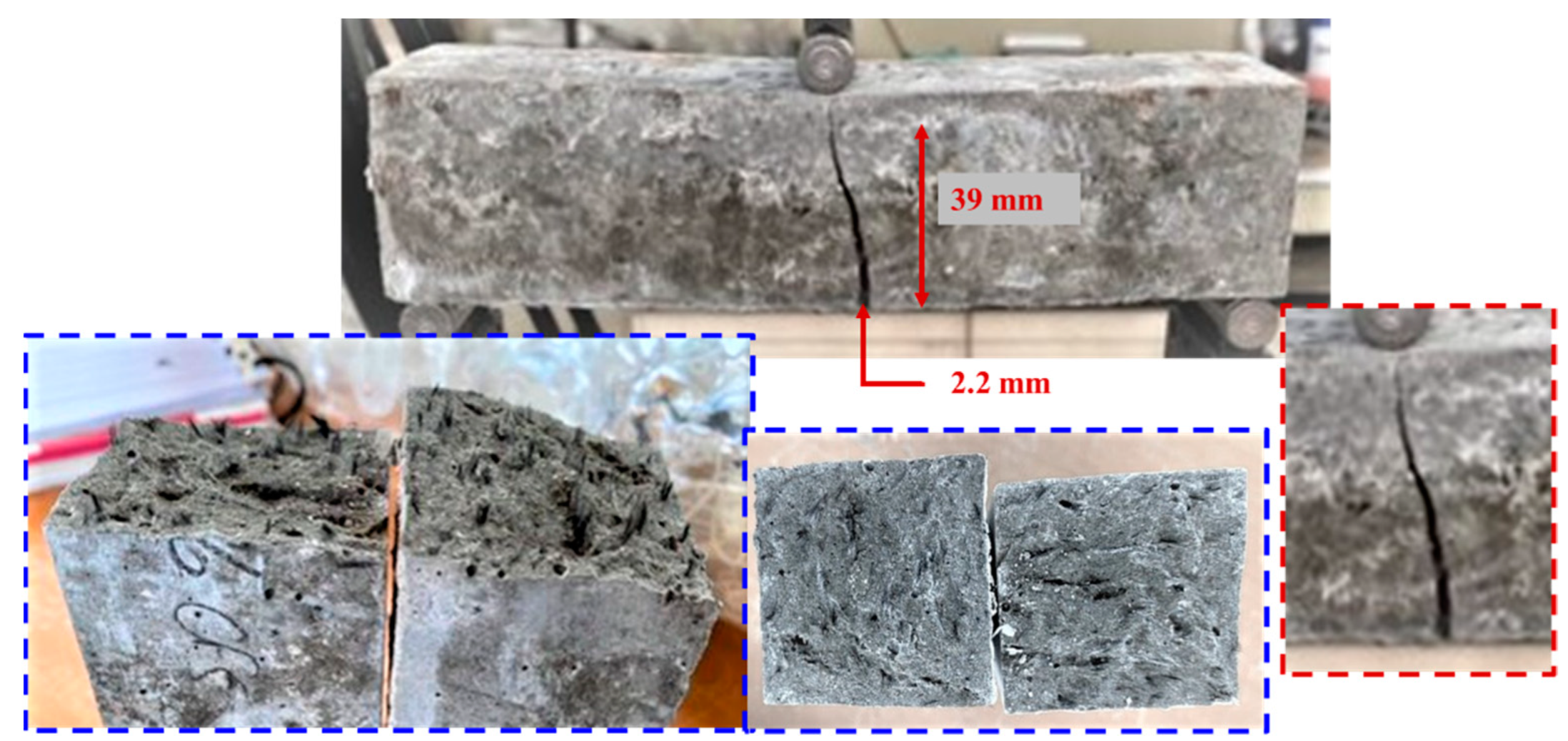
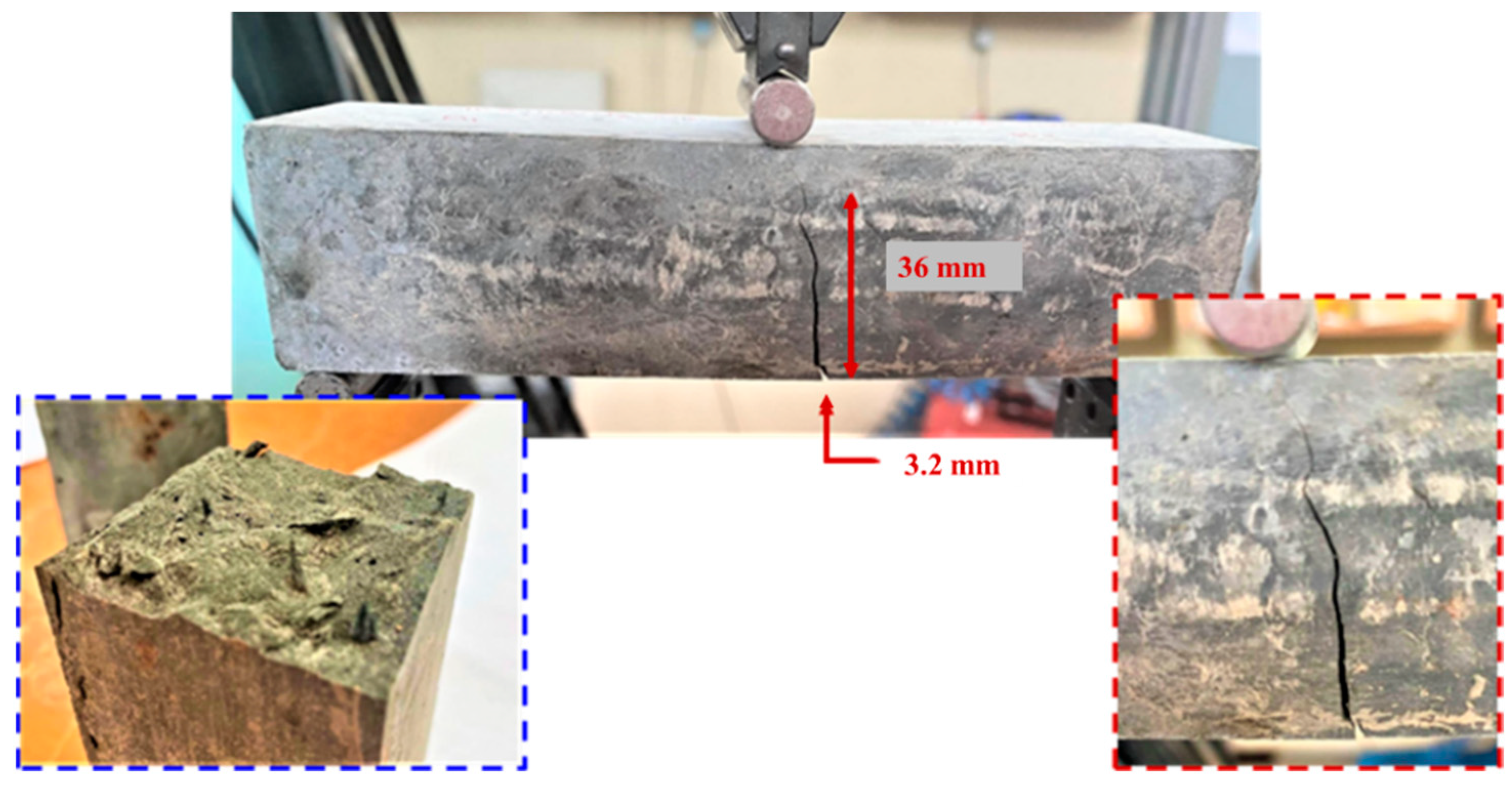
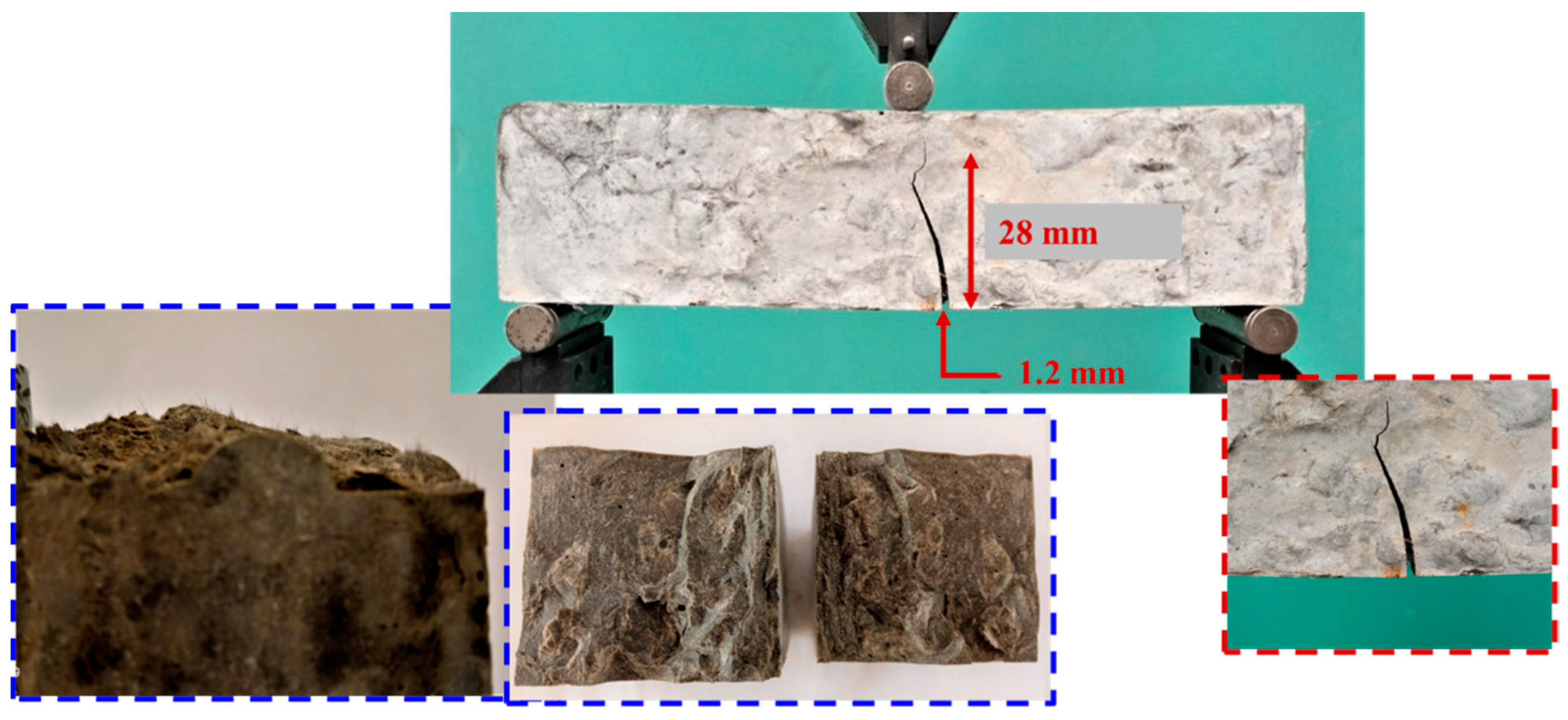
4.3. Failure Mode of Cracking Propagation after the Three-Point Bending Test

The purpose of the experimental tests was to develop a composite cement paste that prevents dwarf and micro-scale cracking and leads to controlled merging and dissemination of it on a macro scale. It was detected that the mechanical performance of the modified materials was not only significantly improved by the addition of fibers at the microscale but were also able to take on additional charge and presented the ability to absorb energy after the formation of the first crack without losing their load-bearing capacity immediately. Below, images of the results of failure modes and concentration of agglomerates at the rupture interface for the different mixing methods are presented.
As can be observed in Figure 11, the crack width of the cement specimen after the bending test, with the method of manually wet mixing of CFs and SP addition, is 3.0 mm, and the length is 29 mm. The CF concentration is depicted at the rupture interface, where masses of agglomerates are not found in the cement volume.
From the photographs and the crack width measurements represented in Figure 12, it can be pointed out that the crack width of the cement specimen after the bending test, with the method case of wet mixing of CFs adding SP and using 60 min sonication, is 3.5 mm and the length is 35 mm. The CF concentration is shown at the rupture interface, where masses of agglomerates are not observed in the cement volume, and the microfibers are distinguished, which bridge the micro and macro cracks, increasing the post-peak behavior of composite materials. This fact leads to an increase in the length of the failure area around the edge of the crack, thus reducing its brittle behavior and increasing the energy absorption capability.
From the failure modes and the crack width measurements illustrated in the photographs in Figure 13, Figure 14 and Figure 15, it was detected that the crack width of the cement specimen with the method case of wet mixing of CFs adding the surfactants CNC and CMC, after bending test, was 2.2 and 2.0 mm, and the length was 39 mm and 36 mm, respectively. The CF concentration is shown at the rupture interface, where masses of agglomerates are observed in the cement volume. The black features illustrated in Figure 12, Figure 13, Figure 14, Figure 15, Figure 16 and Figure 17 are the undispersed CFs agglomerates, particularly pronounced in the case of the addition of the surfactants CMC and CNC, as they are depicted in Figure 13 and Figure 14. This fact implies the existence of weak points where the concentration of stresses leads to the development of early cracks and brittle failure while decreasing the energy absorption capability. In the present study, the mixtures were not examined in terms of workability. We only noticed by visual observation that the addition of CMC and CNC led to workability degradation. This implies mechanical performance deterioration.
Furthermore, in Figure 16 and Figure 17, the crack width of the specimen with the dry mixing method of carbon with and without SP, after the bending test, is 3.2 and 1.2 mm, and the length is 36 mm and 28 mm, respectively. Consequently, in the case of the dry mixing method without SP, there is a significant reduction in crack length, thus indicating the effect of CFs, also, the good dispersion of the sensors. The former procedure bridges the cracks in the microscale by increasing the tensile strength of the die, while the latter delay the propagation of the cracks in the micro-scale, improving the ductility of the material.

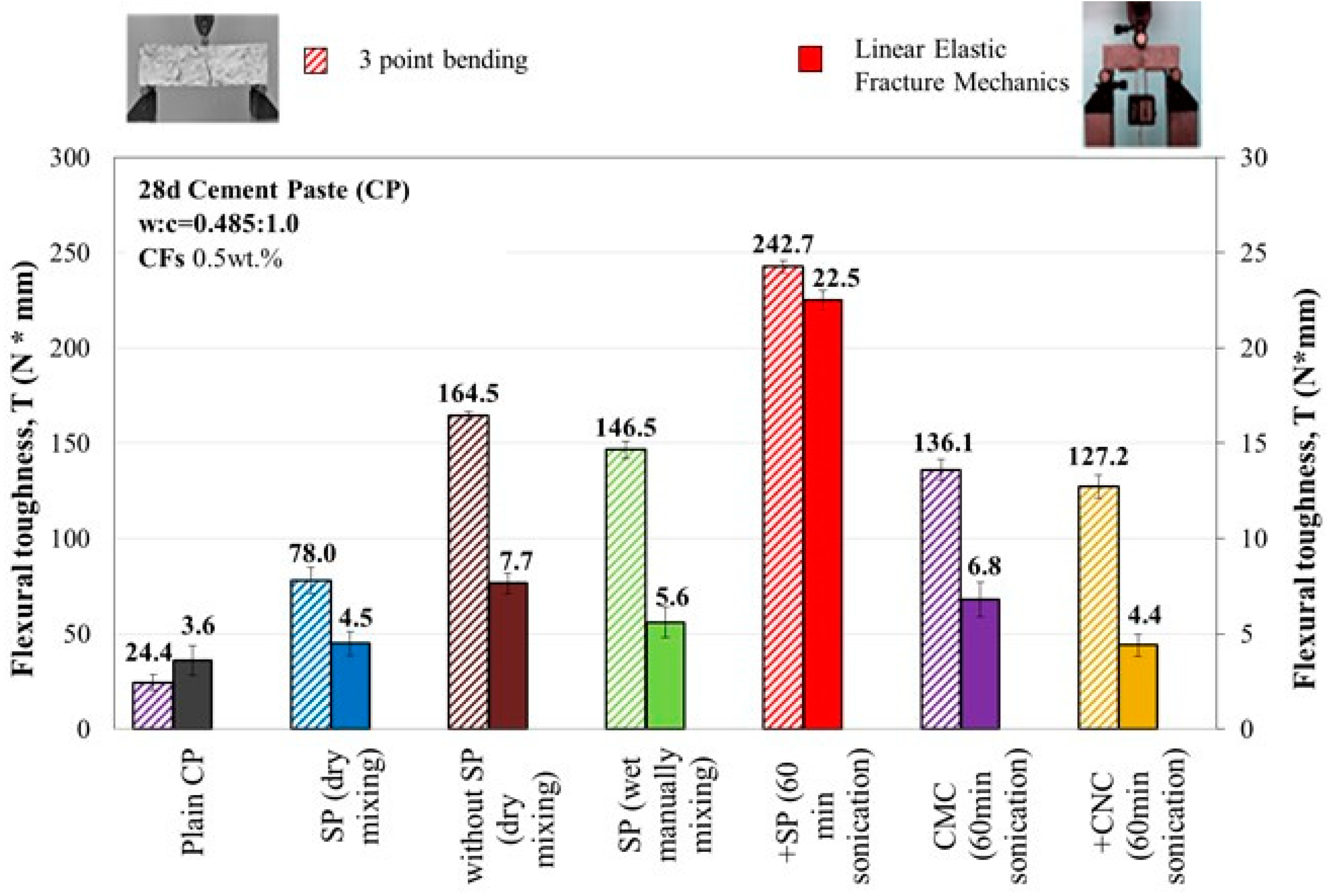
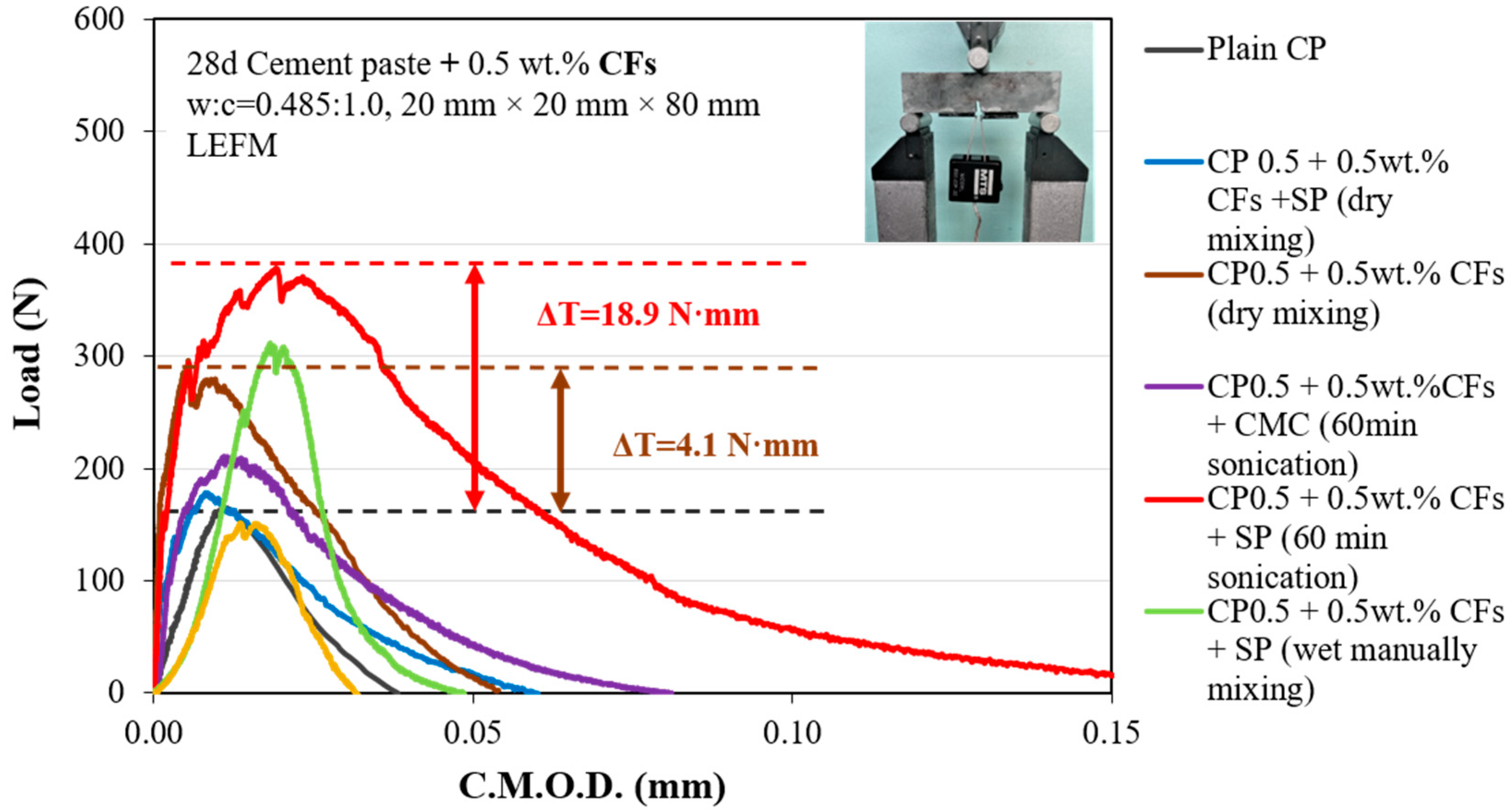
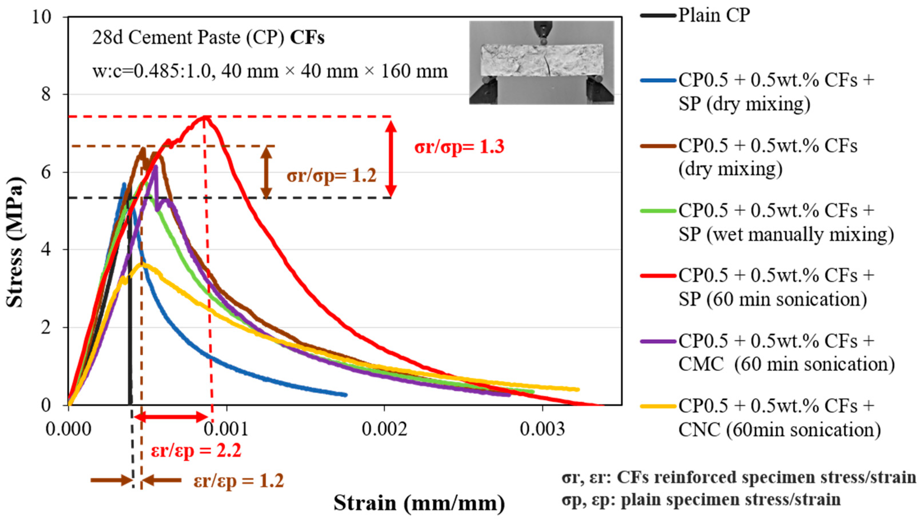
4.4. Effect of Micro-Scale Fiber Incorporation on the Energy Absorption Capability

The flexural toughness, T, represents the energy absorption capability, which is the amount of energy per unit of basal area of the sample in a certain deformation. In order to examine the flexural toughness of the concrete enhanced with fibers, the load to deflection response of an unnotched sample that is obtained up to prescribed deflection levels is widely implemented. Nevertheless, the failure of concrete is often related to crack propagation. Hence, the estimation of toughness based directly on the prismatic beam’s deflection results in errors associated with the external deformations and unstable control except for the first crack formation and the peak load [46]. The fracture mechanics tests on notched prismatic samples are more effective than the conventional three-point bending processes, as they handle only one critical section and one propagating macrocrack. The notch that is formed in the prismatic beams before the testing localizes the crack along its plane, reducing the variability of the crack path and non-symmetry of the deformations, both of which can appear in unnotched beams [48,51,52].
Regarding the fracture mechanics tests, there are three advantages of using a CMOD curve instead of a load–deflection curve from a three-point bending test in an unnotched sample. Firstly, the easier measurement of an extensometer in the CMOD instead of the use of strain gauges attached to the sample’s surface to calculate the deflection. Furthermore, the use of CMOD helps to measure the deformation across the critical section, which is the crack plane, directly. Finally, the CMOD is much more sensitive to failure. In this research, (i) the part under the load-deflection curves from three-point bending tests of 40 × 40 × 160 mm sample and (ii) the part under the load–CMOD curves from LEFM tests of 20 × 20 × 80 mm samples were used to measure the flexural toughness.
The load–CMOD curves of the 28-day plain and 0.5 vol% CFs cement paste micro composites with different mixing methods are presented in Figure 18. The addition of CFs impressively increases the pre-peak and post-crack mechanical performance of micro-reinforced cement pastes. Specifically, the incorporation of CFs provides the cement paste’s ability to receive a higher load for the same crack mouth opening displacement, and as a result, leads to the high increases in flexural strength and Young’s modulus, respectively. In addition to the increases in the strength and stiffness it is also reported that an increase in the flexural toughness performance of the micro-composites occurs, as indicated by the bigger area under the load–CMOD curve. The addition of CFs leads to the enhancement of the crack-bridging mechanism over the maximum load, which is the maximum limit of the proportionality of the load-CMOD curve, allowing the micro-composites to sustain a much higher load until their total failure. Two certain parameters are considered to improve the strength, stiffness, and energy absorbed before failure of the micro-composites. These parameters include the quality of CFs’ dispersion and the high aspect ratio of microfibers in the outer CFs surface, leading to a strong bond in the interface among the cement matrix and the CFs that greatly improves the observed toughening effect [60,61,62].
According to the LEFM theory, the flexural strength and Young’s modulus can be investigated by taking the geometrical characteristics of the notched specimens into consideration, the peak load PL (N), and the compliance Ci (N/mm), which is the slope of the first straight-line portion of the load–deflection curve shown in Figure 19 [52,61,62]. Further, in Figure 20, important progress in the flexural toughness of the specimens at the post-crack stage can be observed from the load–CMOD curves.
After the formation of the first crack, a high ability to transmit the load from the matrix to the CFs is observed for all composites. The cement pastes are reinforced with 60 min ultrasonication CFs, and the addition of SP exhibits a 14.8 N·mm higher energy absorption capability at the post-crack stage than the cement pastes reinforced with the dry mixing method, indicating a complete CF distribution in the mortar matrix.

5. Conclusions

This paper investigates the effects of mixing methods and dispersions with 0.5 wt.% CFs in cement paste, adding three types of surfactants: carboxymethyl cellulose (CMC), nanocrystal cellulose solution (CNC), and superplasticizer (SP). All of these additives were used along with CFs and were applied to estimate the dispersion of CFs in the cementitious materials. The results reveal that the CFRC mixtures exhibit an improved mechanical performance under both flexural and compression loading, as well as an enhanced piezoresistive response. Two main methods were applied to estimate the dispersion of CFs in the matrix, the dry and the wet mixture. The level of dispersion by the application of admixtures such as SP, CNC, and CMC solution in the wet mixing method case, as well as in CFs dry mixing with and without SP, is reflected in the failure mode. The shortcomings of every method were pointed out and analyzed. It was concluded that:
(1)
Among the three kinds of dispersants, SP is superior for improving the fiber dispersion, so its effect is also addressed. Therefore, it was demonstrated that SP could be characterized as the most efficient admixture for giving high tensile and compressive strength.
(2)
The 60 min ultrasonic vibration of SP dispersant treatment can significantly improve the fiber dispersion in the solution and can be further upgrade the mechanical performance. The compressive and flexural strength of CFRC increases due to the carbon micro-fiber dispersion, presenting a strengthening effect on CFRC. As the strength is significantly affected by the matrix defects, it is not valid for the evaluation of the fiber dispersion.
(3)
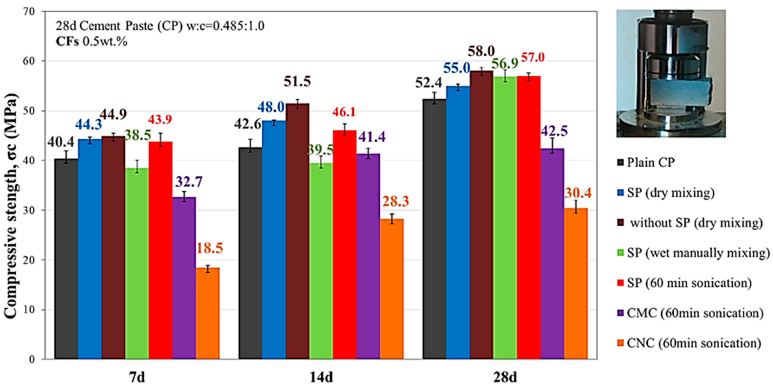
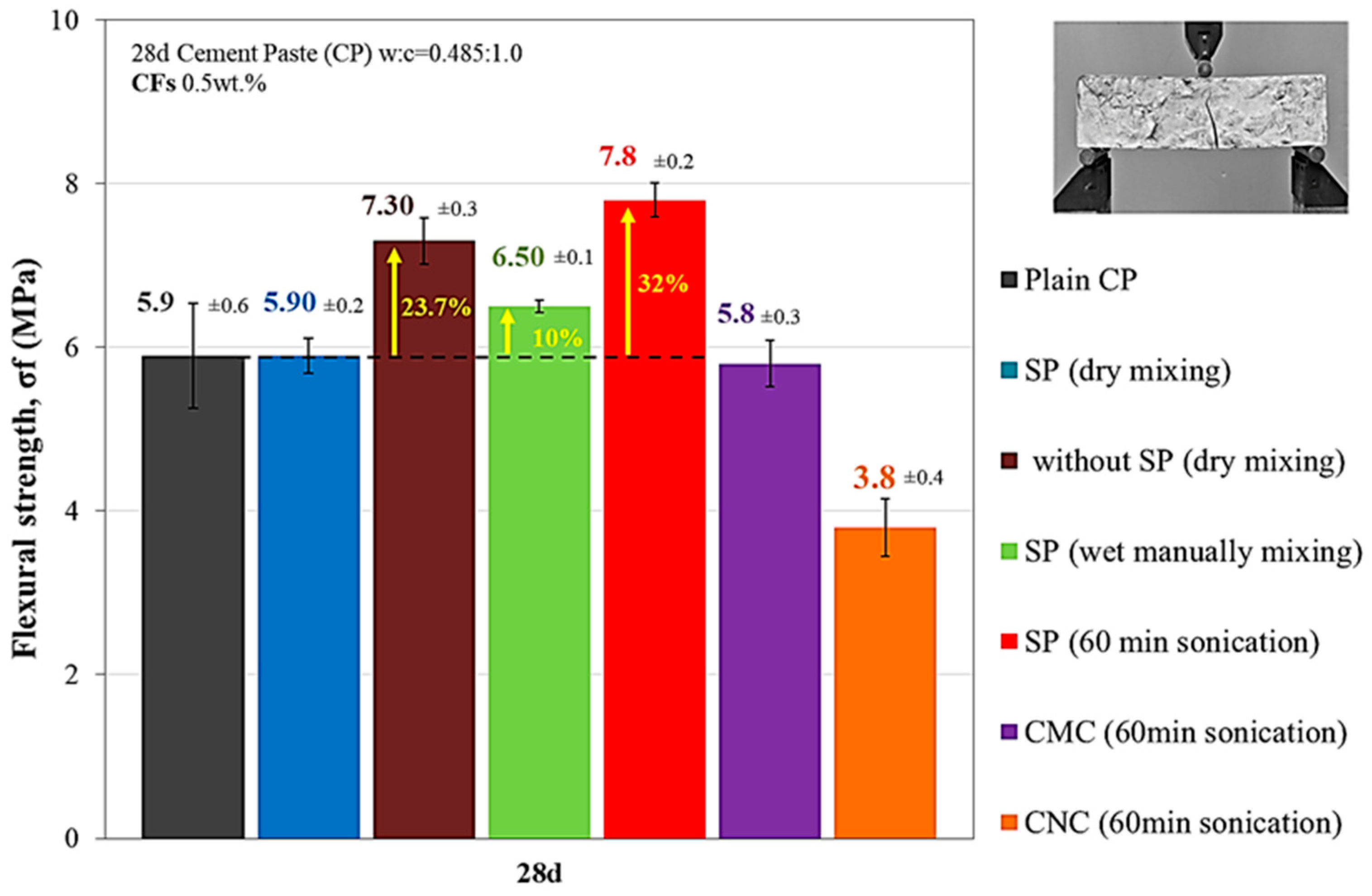
The compressive strength increased by 10.4% with the method of dry mixing without SP, while with the wet method of SP addition and simple agitation with a manual stirrer by 8.6%. The flexural strength increased by 32% with the wet method of adding SP using 60 min sonication and by 24% with the method of dry mixing of CFs without SP.
(4)
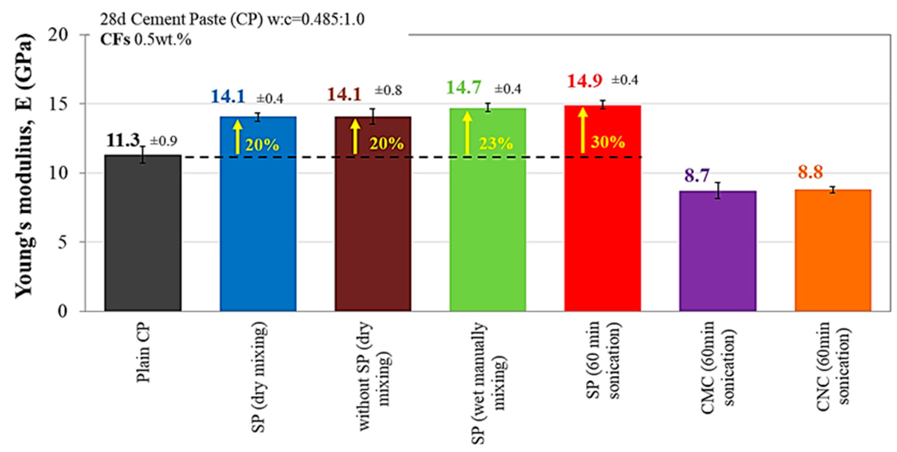
The modulus of elasticity of CFRC is improved significantly by almost 6% by the addition of CFs adding SP and using 60 min sonication compared to the plain specimen and all other methods.
(5)
The addition of CMC and CNC with fiber is the least advantageous, leading to a deterioration of the compressive strength; also, the reduction in flexural strength and the modulus of elasticity is significant.
(6)
The dry-mixed specimen exhibits an improved piezoresistive performance and better linear variation of sensitivity. It constitutes an adequate strain and crack sensor and is also the most economical method compared to the rest mixing methods.
The results prove the dual role of micro-enhancement. The network of microfibers, on the one hand, contributes to the bridging of the cracks that appear at the micro-level and to their controlled joining on the micro and macro scale by increasing the resistance of the material to cracking (with the simultaneous strength and modulus of elasticity enhancement) enhances the microfiber/matrix affinity trends and the load transfer capacity by improving the post-cracking behavior of the reinforced material and increasing its ductility. Finally, the combination of the most economical CFs introduction in cement-based smart sensors with the great mechanical and piezoresistive response institutes a suggested reinforcement method for structural-health monitoring systems. The authors propose the most economical method without using ultrasonication for practical reasons, as this is not feasible for application in large projects, limiting the production process of the multifunctional materials. In our future steps, further research could be orientated towards investigating the microstructure of the reinforced cementitious materials with the different dispersal methods. In addition, it would be useful to study the effect of the fiber content in the matrix, as well as its combination of thermal and electrical conductivity sensors.

Author Contributions

Conceptualization, A.K.T. and M.G.F.; methodology, A.K.T. and M.G.F.; software, A.K.T. and M.G.F.; validation, A.K.T. and M.G.F.; formal analysis, A.K.T., M.G.F. and F.I.G.; investigation, A.K.T., M.G.F., F.I.G. and C.E.C.; resources, C.E.C.; data curation, A.K.T. and M.G.F.; writing—original draft preparation, A.K.T.; writing—review and editing, A.K.T., M.G.F., F.I.G., C.E.C. and A.E.; visualization, A.K.T. and C.E.C.; supervision, C.E.C. and A.E.; project administration, A.E. All authors have read and agreed to the published version of the manuscript.

Funding

This research has been co-financed by the European Union and Greek national funds through the Operational Program Competitiveness, Entrepreneurship, and Innovation, under the call RESEARCH-CREATE-INNOVATE (HICOTEG-T1EDK-03482).

Institutional Review Board Statement

Not applicable.

Informed Consent Statement

Not applicable.

Data Availability Statement

The data presented in this study are available on request from the corresponding author.

Acknowledgments

The authors thankfully appreciate the cooperation of collaborators of the Composite & Smart Material Laboratory of Materials Science and Engineer Department for providing the CFs, also the Reinforced Concrete and Seismic Design of Structures Laboratory at the Democritus University of Thrace.

Conflicts of Interest

The authors state no conflict of interest.

References

  1. Reza, F.; Batson, G.B.; Yamamuro, J.A.; Lee, J.S. Resistance changes during compression of carbon fiber cement compo-sites. J. Mater. Civ. Eng. 2003, 15, 476–483. [Google Scholar] [CrossRef] [Green Version]
  2. Cao, J.; Chung, D.D.L. Carbon fiber reinforced cement mortar improved by using acrylic dispersion as an admixture. Cem. Concr. Res. 2001, 31, 1633–1637. [Google Scholar] [CrossRef]
  3. Chen, P.W.; Fu, X.; Chung, D.D.L. Microstructural and mechanical effects of latex, methylcellulose, and silica fume on carbon fiber reinforced cement. Mater. J. 1997, 94, 147–155. [Google Scholar]
  4. Wang, H.; Gao, X.; Wang, R. The influence of rheological parameters of cement paste on the dispersion of carbon nanofibers and self-sensing performance. Constr. Build. Mater. 2017, 134, 673–683. [Google Scholar] [CrossRef]
  5. Alanazi, H.; Alharbi, Y.R.; Abadel, A.A.; Elalaoui, O. Effect of edge oxidized graphene oxide on micro and macro mechanical properties and microstructure of cement paste. Int. J. Mater. Res. 2022, 113, 271–277. [Google Scholar] [CrossRef]
  6. Al Qader, H.; Jasim, A.M.; Salim, H.; Xing, Y.; Stalla, D. Enhanced Mechanical and Durability Properties of Cement Mortar by Using Alumina Nanocoating on Carbon Nanofibers. Materials 2022, 15, 2768. [Google Scholar] [CrossRef]
  7. Brown, L.; Stephens, C.S.; Allison, P.G.; Sanchez, F. Effect of Carbon Nanofiber Clustering on the Micromechanical Properties of a Cement Paste. Nanomaterials 2022, 12, 223. [Google Scholar] [CrossRef]
  8. Wang, C.; Li, K.Z.; Li, H.J.; Jiao, G.S.; Lu, J.; Hou, D.S. Effect of carbon fiber dispersion on the mechanical properties of carbon fiber-reinforced cement-based composites. Mater. Sci. Eng. A 2008, 487, 52–57. [Google Scholar] [CrossRef]
  9. Sanchez, F.; Ince, C. Microstructure and macroscopic properties of hybrid carbon nanofiber/silica fume cement composites. Compos. Sci. Technol. 2009, 69, 1310–1318. [Google Scholar] [CrossRef]
  10. Chung, D.D. Dispersion of short fibers in cement. J. Mater. Civ. Eng. 2005, 17, 379–383. [Google Scholar] [CrossRef]
  11. Chuang, W.; Geng-sheng, J.; Bing-liang, L.; Lei, P.; Ying, F.; Ni, G.; Ke-zhi, L. Dispersion of carbon fibers and conductivity of carbon fiber-reinforced cement-based composites. Ceram. Int. 2017, 43, 15122–15132. [Google Scholar] [CrossRef]
  12. Konsta-Gdoutos, M.S.; Batis, G.; Danoglidis, P.; Zacharopoulou, A.K.; Zacharopoulou, E.K.; Falara, M.G.; Shah, S.P. Effect of CNT and CNF loading and count on the corrosion resistance, conductivity and mechanical properties of nanomodified OPC mortars. Constr. Build. Mater. 2017, 147, 48–57. [Google Scholar] [CrossRef]
  13. Toutanji, H.; McNeil, S.; Bayasi, Z. Chloride permeability and impact resistance of polypropylene-fiber-reinforced silica fume concrete. Cem. Concr. Res. 1998, 28, 961–968. [Google Scholar] [CrossRef]
  14. EFNARC (European Federation of National Associations Representing for Concrete). Specification and Guidelines for Self-Compacting Concrete. European 29 Federation of National Associations Representing Producers and Applicators of Specialist 30 Building Products for Concrete (EFNARC), 32:31. 2005. Available online: http://www.efnarc.org/pdf/SCCGuidelinesMay2005.pdf (accessed on 1 May 2005).
  15. Gull, I.; Tantray, M. Effect of Super Plasticizers on Fresh and Hardened State Properties of Short Carbon Fiber Reinforced Electrically Conductive Concrete. Int. J. Recent Technol. Eng. 2020, 8. [Google Scholar] [CrossRef]
  16. Ivorra, S.; Garcés, P.; Catalá, G.; Andión, L.G.; Zornoza, E. Effect of silica fume particle size on mechanical proper-ties of short carbon fiber reinforced concrete. Mater. Des. 2010, 31, 1553–1558. [Google Scholar] [CrossRef]
  17. Wen, S.; Chung, D. Seebeck effect in carbon fiber-reinforced cement. Cem. Concr. Res. 1999, 29, 1989–1993. [Google Scholar] [CrossRef]
  18. Wen, S.; Chung, D. Carbon fiber-reinforced cement as a thermistor. Cem. Concr. Res. 1999, 29, 961–965. [Google Scholar] [CrossRef]
  19. Endo, M.; Kim, Y.A.; Ezaka, M.; Osada, K.; Yanagisawa, T.; Hayashi, T.; Terrones, M.; Dresselhaus, M.S. Selective and efficient impregnation of metal nanoparticles on cup-stacked-type carbon nanofibers. Nano Lett. 2003, 3, 723–726. [Google Scholar] [CrossRef]
  20. Ismagilov, Z.R.; Shalagina, A.E.; Podyacheva, O.Y.; Ischenko, A.V.; Kibis, L.S.; Boronin, A.I.; Chesalov, Y.A.; Kochubey, D.I.; Romanenko, A.I.; Anikeeva, O.B.; et al. Structure and electrical conductivity of nitrogen-doped carbon nanofibers. Carbon 2009, 47, 1922–1929. [Google Scholar] [CrossRef]
  21. Safiuddin; Yakhlaf, M.; Soudki, K. Key mechanical properties and microstructure of carbon fibre reinforced self-consolidating concrete. Constr. Build. Mater. 2018, 164, 477–488. [Google Scholar] [CrossRef]
  22. Voutetaki, M.E.; Papadopoulos, N.A.; Angeli, G.M.; Providakis, C.P. Investigation of a new experimental method for damage assessment of RC beams failing in shear using piezoelectric transducers. Eng. Struct. 2016, 114, 226–240. [Google Scholar] [CrossRef]
  23. Chalioris, C.E.; Kytinou, V.K.; Voutetaki, M.E.; Karayannis, C.G. Flexural Damage Diagnosis in Reinforced Concrete Beams Using a Wireless Admittance Monitoring System—Tests and Finite Element Analysis. Sensors 2021, 21, 679. [Google Scholar] [CrossRef] [PubMed]
  24. Voutetaki, M.E.; Providakis, C.P.; Chalioris, C.E. FRP debonding prevention of strengthened concrete members un-der dynamic load using smart piezoelectric materials (PZT). In Proceedings of the 15th European Conference on Composite Materials: Composites at Venice, ECCM 2012, Venice, Italy, 24–28 June 2012; p. 106145. [Google Scholar]
  25. Chen, P.W.; Chung, D.D.L. Concrete reinforced with up to 0.2 vol% of short carbon fibres. Composites 1993, 24, 33–52. [Google Scholar] [CrossRef]
  26. Cholker, A.K.; Tantray, M.A. Micro carbon fiber based concrete as a strain-damage sensing material. Mater. Today Proc. 2019, 19, 152–157. [Google Scholar] [CrossRef]
  27. Giraud, I.; Franceschi-Messant, S.; Perez, E.; Lacabanne, C.; Dantras, E. Preparation of aqueous dispersion of thermoplastic sizing agent for carbon fiber by emulsion/solvent evaporation. Appl. Surf. Sci. 2013, 266, 94–99. [Google Scholar] [CrossRef] [Green Version]
  28. Cholker, A.K.; Kavyateja, B.V.; Reddy, P.N. Influence of Carbon Fibers on Strain and Damage Sensing of Self Compacting Concrete under External Applied Forces. Instrum. Mes. Métrologie 2019, 18, 559–565. [Google Scholar] [CrossRef]
  29. Pozegic, T.R.; Huntley, S.; Longana, M.L.; He, S.; Bandara, R.M.I.; King, S.G.; Hamerton, I. Improving Dispersion of Recycled Discontinuous Carbon Fibres to Increase Fibre Throughput in the HiPerDiF Process. Materials 2020, 13, 1544. [Google Scholar] [CrossRef] [Green Version]
  30. Han, B.; Zhang, K.; Yu, X.; Kwon, E.; Ou, J. Fabrication of Piezoresistive CNT/CNF Cementitious Composites with Superplasticizer as Dispersant. J. Mater. Civ. Eng. 2012, 24, 658–665. [Google Scholar] [CrossRef]
  31. Bentz, D.; Jensen, O.; Coats, A.; Glasser, F. Influence of silica fume on diffusivity in cement-based materials: I. Experimental and computer modeling studies on cement pastes. Cem. Concr. Res. 2000, 30, 953–962. [Google Scholar] [CrossRef]
  32. Chung, D.D.L. Review: Improving cement-based materials by using silica fume. J. Mater. Sci. 2002, 37, 673–682. [Google Scholar] [CrossRef]
  33. Danoglidis, P.A.; Konsta-Gdoutos, M.S.; Shah, S.P. Relationship between the carbon nanotube dispersion state, electrochemical impedance and capacitance and mechanical properties of percolative nanoreinforced OPC mortars. Carbon 2018, 145, 218–228. [Google Scholar] [CrossRef]
  34. Fu, X.; Chung DD, L. Effects of silica fume, latex, methylcellulose, and carbon fibers on the thermal conductivity and specific heat of cement paste. Cem. Concr. Res. 1997, 27, 1799–1804. [Google Scholar] [CrossRef]
  35. Fu, X.; Lu, W.; Chung, D. Improving the bond strength between carbon fiber and cement by fiber surface treatment and polymer addition to cement mix. Cem. Concr. Res. 1996, 26, 1007–1012. [Google Scholar] [CrossRef]
  36. Chen, P.W.; Chung, D.D.L. Comparative study of concretes reinforced with carbon, polyethylene, and steel fibers and their improvement by latex addition. ACI Mater. J. 1996, 93, 129–133. [Google Scholar]
  37. Hou, J.; Chung, D. Effect of admixtures in concrete on the corrosion resistance of steel reinforced concrete. Corros. Sci. 2000, 42, 1489–1507. [Google Scholar] [CrossRef]
  38. Fu, X.; Chung, D.D.L. Improving the bond strength of concrete to reinforcement by adding methylcellulose to concrete. ACI Mater. J. 1998, 95, 601–608. [Google Scholar]
  39. Xu, Y.; Chung, D. Effect of carbon fibers on the vibration-reduction ability of cement. Cem. Concr. Res. 1999, 29, 1107–1109. [Google Scholar] [CrossRef]
  40. Chen, P.-W.; Chung, D.D.L. Carbon Fiber Reinforced Concrete as an Electrical Contact Material for Smart Structures; SAMPE: Covina, CA, USA; Anaheim, CA, USA, 1993; pp. 2067–2076. [Google Scholar]
  41. Maria, F.; Athanasia, T.; Fani, G.; Anaxagoras, E. CNT amount and type: Crucial parameters in mechanical performance enhancement on cement paste nanocomposites. In Proceedings of the 2021 International Conference on Frontiers of Nanomaterials and Nanotechnology (NanoMT 2021), Singapore, 15–17 October 2021. [Google Scholar]
  42. Kim, Y.; McCoy, L.T.; Feit, C.; Mubarak, S.A.; Sharma, S.; Minko, S. Carboxymethyl Cellulose Enhanced Production of Cellulose Nanofibrils. Fibers 2021, 9, 57. [Google Scholar] [CrossRef]
  43. Trache, D.; Thakur, V.; Boukherroub, R. Cellulose Nanocrystals/Graphene Hybrids—A Promising New Class of Materials for Advanced Applications. Nanomaterials 2020, 10, 1523. [Google Scholar] [CrossRef]
  44. Antosik, A.K.; Wilpiszewska, K. Influence of cellulose fibers on physicochemical properties of biodegradable films based on polysaccharide derivatives. Open Agric. 2020, 5, 462–465. [Google Scholar] [CrossRef]
  45. Metaxa, Z.; Tolkou, A.; Efstathiou, S.; Rahdar, A.; Favvas, E.; Mitropoulos, A.; Kyzas, G. Nanomaterials in Cementitious Composites: An Update. Molecules 2021, 26, 1430. [Google Scholar] [CrossRef] [PubMed]
  46. Danoglidis, P.A.; Gdoutos, E.E.; Konsta-Gdoutos, M.S. Designing Carbon Nanotube and Nano-fiber-Polypropylene Hybrid Cementitious Composites with Improved Pre-and Post-Crack Load Carrying and Energy Absorption Capacity. Eng. Fract. Mech. 2022, 262, 108253. [Google Scholar] [CrossRef]
  47. Falara, M.G.; Konsta-Gdoutos, M.S.; Gdoutos, E.E. Enhanced Post-crack Load Carrying Capacity of Nano and Micro Scale Carbon Fiber Reinforced Mortars. In Proceedings of the International Conference on Theoretical, Applied and Experimental Mechanics, Corfu, Greece, 23–26 June 2019. [Google Scholar]
  48. Safiuddin; Abdel-Sayed, G.; Hearn, N. Flexural and Impact Behaviors of Mortar Composite Including Carbon Fibers. Materials 2022, 15, 1657. [Google Scholar] [CrossRef] [PubMed]
  49. Hunashyal, A.M.; Lohitha, S.J.; Quadri, S.S.; Banapurmath, N.R. Experimental investigation of the effect of car-bon nanotubes and carbon fibres on the behaviour of plain cement composite beams. IES J. Part A Civ. Struct. Eng. 2011, 4, 29–36. [Google Scholar] [CrossRef]
  50. Jamet, D.; Gettu, R.; Gopalaratnam, V.S.; Aguado, A. Toughness of Fiber-Reinforced High-Strength Concrete from Notched Beam Tests; ACI Special Publications 155: Testing of Fiber Reinforced Concrete; Special Publication: Tulsa, Oklahoma, 1995; Volume SP 155, pp. 23–40. [Google Scholar]
  51. Martinelli, E.; Pepe, M.; Fraternali, F. Meso-Scale Formulation of a Cracked-Hinge Model for Hybrid Fiber-Reinforced Cement Composites. Fibers 2020, 8, 56. [Google Scholar] [CrossRef]
  52. Metaxa, Z.S.; Boutsioukou, S.; Amenta, M.; Favvas, E.P.; Kourkoulis, S.K.; Alexopoulos, N.D. Dispersion of Multi-Walled Carbon Nanotubes into White Cement Mortars: The Effect of Concentration and Surfactants. Nanomaterials 2022, 12, 1031. [Google Scholar] [CrossRef]
  53. Barr, B.I.G.; Gettu, R.; Al-Oraimi, S.K.A.; Bryars, L.S. Toughness Measurement-The need to thing again. Cem. Concr. Compos. 1996, 18, 281–297. [Google Scholar] [CrossRef]
  54. Taylor, M.; Lydon, F.; Barr, B. Toughness measurements on steel fibre-reinforced high strength concrete. Cem. Concr. Compos. 1997, 19, 329–340. [Google Scholar] [CrossRef]
  55. Wen, S.; Chung, D.D.L. Piezoresistivity-based strain sensing in carbon fiber reinforced cement. ACI Mater. J. 2007, 104, 171–179. [Google Scholar]
  56. ASTM C305-14 Standard Practice for Mechanical Mixing of Hydraulic Cement Pastes and Mortars of Plastic Consistency; ASTM International: West Conshohocken, PA, USA, 1995.
  57. Akihama, S.; Suenaga, T.; Banno, T. Mechanical properties of carbon fibre reinforced cement composites. Int. J. Cem. Compos. Light. Concr. 1986, 8, 21–33. [Google Scholar] [CrossRef]
  58. Hambach, M.; Moller, H.; Neuman, T.; Volkmer, D. Portland cement paste with aligned carbon fibers exhibiting exceptionally high flexural strength (>100 MPa). Cem. Concr. Res. 2016, 89, 80–86. [Google Scholar] [CrossRef]
  59. Azhari, F.; Banthia, N. Cement-based sensors with carbon fibers and carbon nanotubes for piezoresistive sensing. Cem. Concr. Compos. 2012, 34, 866–873. [Google Scholar] [CrossRef]
  60. Gdoutos, E.E.; Konsta-Gdoutos, M.S.; Danoglidis, P. Portland cement mortar nanocomposites at low carbon nanotube and carbon nanofiber content: A fracture mechanics experimental study. Cem. Concr. Compos. 2016, 70, 110–118. [Google Scholar] [CrossRef]
  61. Shah, S.P.; Swartz, S.E.; Ouyang, C. Fracture Mechanics of Concrete: Application of Fracture Mechanics to Concrete, Rock and Other Quasi-Brittle Materials; John Wiley and Sons: New York, NY, USA, 1995. [Google Scholar]
  62. Gdoutos, E.E. Fracture Mechanics: An Introduction, 2nd ed.; Springer Netherlands: Berlin/Heidelberg, Germany, 2005. [Google Scholar]
Figure 1. (a) Methods of 0.5 wt.% CFs introduction in cement pastes, (b) Carbon fibers (CFs).
Fibers 10 00049 g001
Figure 2. Three-point bending experimental setup with laser measurement.
Fibers 10 00049 g002
Figure 3. The test setup and instrumentations for the piezoresistivity measurements.
Fibers 10 00049 g003
Figure 4. (a) Different wet dispersant and mixing methods of CFs and (b) dry mixing methods.
Fibers 10 00049 g004
Figure 5. Compressive strength of plain cement pastes and CFs reinforced cementitious composites.
Fibers 10 00049 g005
Figure 6. Flexural strength of 28-day plain cement pastes and CFs reinforced cementitious composites.
Fibers 10 00049 g006
Figure 7. Young’s Modulus of 28-day plain cement pastes and CFs reinforced cementitious composites.
Fibers 10 00049 g007
Figure 8. Conductivity values of 28-day plain cement pastes and cementitious CFs reinforced composites reinforced incorporated by different methods.
Fibers 10 00049 g008
Figure 9. Piezoresistivity response of 28-day plain and reinforced cement paste composites with CFs incorporated by different methods.
Fibers 10 00049 g009
Figure 10. Piezoresistive behavior under monotonic loading of 28-d plain and reinforced cement paste composites with CFs incorporated by different methods.
Fibers 10 00049 g010
Figure 11. Crack width and length after three-point bending test and CFs concentration at the rupture interface in the case of simple manually wet manually mixing of CFs and SP addition.
Fibers 10 00049 g011
Figure 12. Crack width and length after bending test and CFs concentration at the rupture interface in the case of wet mixing of CFs adding SP and using 60 min sonication.
Fibers 10 00049 g012
Figure 13. Crack width and length after bending test and CFs concentration at the rupture interface in the case of wet mixing of CFs adding Carboxymethyl Nanocrystal (CMC).
Fibers 10 00049 g013
Figure 14. Crack width and length after bending test and CFs concentration at the rupture interface in the case of wet mixing of CFs adding CNC.
Fibers 10 00049 g014
Figure 15. CFs concentration at the rupture interface in the case of (a) wet mixing of CFs adding CMC, (b) wet mixing of CFs adding CNC, and (c) Plain cement paste.
Fibers 10 00049 g015
Figure 16. Crack width and length after three-point bending test and CFs concentration at the rupture interface in the case of simple dry mixing of CFs with SP addition.
Fibers 10 00049 g016
Figure 17. CFs concentration at the rupture interface in the case of CFs’ dry mixing method.
Fibers 10 00049 g017
Figure 18. Flexural toughness of the 28-day cement pastes as estimated from the area under the load-deflection (three-point bending) and load-CMOD curves (LEFM).
Fibers 10 00049 g018
Figure 19. Load–CMOD curves of 28-day plain and CFs composite cement pastes at volume fractions of 0.5% from LEFM tests of 20 mm × 20 mm × 80 mm specimens.
Fibers 10 00049 g019
Figure 20. Stress-strain curves of 28-day plain and reinforced with CFs cement pastes at volume fractions of 0.5% from three-point bending tests of 40 mm × 40 mm × 160 mm specimens.
Fibers 10 00049 g020
Table 1. Properties of Carbon fibers.
Carbon
Content
Tensile StrengthTensile ModulusStrain at FailureDensityFilament DiameterLengthElectric Resistivity
(%)(MPa)(GPa)(%)(gr/cm3)(μm)(mm)(Ω·cm)
9549002302.11.8761.6 × 10−3
Table 2. Electrical resistivity values and average change in resistivity Δρ/ρ0 (%) of 28-day plain and cement paste micro-composites reinforced with CFs.
CP0.485+CFs 0.5 wt.%Electrical Resistivity (Ohm·m)Average Change in Resistivity Δρ/ρ0 (%)
SP (dry mixing)20.73.4
Without SP (dry mixing)20.918.5
SP (wet manually mixing)20.09.5
SP (60 min sonication)15.420.2
CMC (60 min sonication)59.83.4
CNC (60 min sonication)29.78.8
Publisher’s Note: MDPI stays neutral with regard to jurisdictional claims in published maps and institutional affiliations.

