Article

Influence of Carbon Fiber-Reinforced Ropes Applied as External Diagonal Reinforcement on the Shear Deformation of RC Joints

by
Chris Karayannis
1,*,
Emmanouil Golias
1 and
George I. Kalogeropoulos
2
1
Laboratory of Reinforced Concrete and Seismic Design of Structures, Democritus University of Thrace, 67100 Xanthi, Greece
2
Laboratory οf Reinforced Concrete and Masonry Structures, Aristotle University of Thessaloniki, 54636 Thessaloniki, Greece
*
Author to whom correspondence should be addressed.
Fibers 2022, 10(3), 28; https://doi.org/10.3390/fib10030028
Submission received: 2 December 2021 / Revised: 14 February 2022 / Accepted: 1 March 2022 / Published: 10 March 2022

Abstract

:
The use of the innovative material of Carbon Fiber-Reinforced (C-FRP) ropes as external near surface mounted reinforcement for the strengthening of reinforced concrete beam-column joints is studied. The ropes are diagonally applied forming external X-type reinforcements on both sides of the joint body. The efficiency of the technique is mainly based on the assumption that the confinement of the joint body due to the applied X-shaped ropes and the contribution of the ropes as shear reinforcement are efficient enough to reduce the shear deformations observed in the joint core during the seismic excitation. Thereof the experimental measurements of the shear deformations of nine full scale beam-column joints tested in cyclic deformations are elaborated and presented herein. The specimens are sorted in two groups. Specimens of group A have been designed in the way that damage is mainly expected in the beam. On the other hand, in order to investigate the efficacy of the use of the ropes for substandard joints the group B specimens have been designed in the way that cracks and some damages are expected to develop in the joint body. Systematic and extended comparative presentations for specimens with and without ropes proved in all the examined cases that the externally mounted C-FRP ropes kept the joint body intact and substantially reduced the shear deformations especially in high drifts. Moreover, the influence of the externally mounted X-shaped C-FRP ropes on the seismic behaviour of these specimens is also examined in terms of the developing principal tensile stresses inside the joint body. From the comparisons of the principal stresses developing in specimens with and without X-form C-FRP ropes it became quite obvious that the ropes kept the joint body intact and allowed the development of higher values of principal stresses comparing with the stresses developing in specimens without ropes.

1. Introduction

Research on the efficiency of strengthening techniques for reinforced concrete elements constitutes a scientific field of utmost importance due to the vital issue of the structures’ safety in seismic prone areas and due to the relevant huge financial interests.
Easily applied techniques for the strengthening of reinforced concrete joints aiming at reducing repair time have been recently reported [1]. Reinforced concrete structures are usually designed and constructed with steel bars as reinforcement. Nevertheless, new materials like Fiber Reinforced Polymers (FRPs) in the form of sheets or bars have also been reported for the strengthening or rehabilitation of deficient or damaged reinforced concrete elements [1,2,3,4,5,6,7,8,9,10,11]. A review with an extensive database extracted from the literature about tested beam-column joints strengthened with FRPs are presented in a state-of-the-art report by Pohoryles et al. [5]. Murad et al. [6] proposed the application of FRP sheets for the rehabilitation of beam-column joints made of recycled concrete. Further, an experimental investigation of the effectiveness of the use an innovative anchor for FRP sheets externally applied for the strengthening of beam-column joints has been experimentally investigated [8,9]. Furthermore, experimental works considering near surface mounted (NSM technique) fiber reinforced plastics have lately been reported [12,13,14,15,16]. A state-of-the-art report for near surface mounted FRPs has also been published [17]. Strengthening techniques using steel products mounted on the surface of concrete elements have also been reported [18,19,20,21]. Further, analytical approaches have been proposed, too [22,23].
Recently the application of fiber reinforced plastics in the form of flexible ropes has been tested as external reinforcement for the strengthening of reinforced concrete elements [24,25]. In particular Karayannis and Golias [26,27] have used Carbon Fiber-Reinforced Plastics (C-FRP) ropes for the strengthening of exterior beam-column yielding useful and promising conclusions. In this case C-FRP ropes are usually applied diagonally, forming external X-shape reinforcements on both sides of the joint. In general, it is stressed that research on the strengthening and repair methods is really a challenging field considering the financial implications after severe seismic events and the fact that the main tool of research in this field is the experiment and especially the testing of real scale specimens. On the other hand, it is emphasized that the use of the externally mounted carbon fiber ropes has an “easy-to-apply character of its application” in comparison to other well-known strengthening techniques like the application of reinforced concrete jacketing, the shotcrete jacketing and others. The efficiency of the technique is mainly based on the assumption that the confinement of the joint body due to the applied X-shaped ropes is efficient enough to reduce the shear deformations observed in the joint core during the seismic excitation. Therefore, in this work an attempt for the study of the influence of the ropes on the observed shear deformation of exterior beam-column joints is presented. The attempted investigation is based on experimental data acquired from an extended experimental project initial results of which have recently been published by the authors [27].

2. Design Purpose of the Joint Specimens

2.1. Characteristics of Specimens—Materials

The characteristics of the specimens have been chosen to be suchlike the ones of the columns and the beams of common structures. The total length of the column part is equal to 3.0 m and its cross-section is 350/250 mm whereas the length of the beam is 1.875 m and its cross-section is 350/250 m. Dimensions and the positions of the reinforcements are presented in Figure 1 whereas the amounts of reinforcements are given in Table 1.
The purpose of the beam-column specimens is the study of the application of diagonally placed C-FRP ropes on each one of the two sides of the joints as strengthening technique (NSM technique) [12,13,14,15,16,17,26,27,28,29].
In this direction the shear deformations of nine full scale specimens of exterior beam-column joints under cyclic loading are presented and examined. The attempted investigation is mainly based on the observed shear deformations of the joint body. The specimens are sorted into two groups (Table 1); group A and group B.
For the compressive strength of concrete supplementary compression tests of six cylinders (150 × 300 mm) were performed; mean value of compressive strength was found fcm = 34 MPa. The steel reinforcement was B500C with mean tensile strength fy = 550 MPa. The C-FRP rope used for the strengthening of specimens JA0F2x2b, JA1F2x2b, JB1Fx and JB1F2x2b is a bundle of unidirectional carbon fibers with tensile strength equal to 4000 MPa, modulus of elasticity equal to 240 GPa and cross-section area > 28 mm2, according to manufacturer’s data (SikaWrap® FX-50 C, SIKA HELLAS SA). Two types of epoxy resins were used: resin type A (Sikadur®-52) for the impregnation of dry fibers and type B (Sika AnchorFix®-3+) for the anchorage of system.

2.2. Examination of the Expected Damage

Detailed examination of the nature of the expected damage of the joint specimens was performed based on a well-known model by Tsonos [30,31,32,33]. This model [30] describes an approach for the determination of the ultimate shear τult and the factor γ ult = τ ult / f c d . Factor γult is then compared to the developing shear γcal where γ c a l = τ c a l / f c d . From this comparison, for group A specimens, it can be seen that γcal≪γult. Thereunder, it can be deduced that the damage is expected to be located in the beam of the specimens and the joint body to remain intact. On the other hand, for the group B specimens, the value of γcal was little less than the value of the ultimate shear γult concluding that the cracking system is expected to be developed both in both the beam and the joint body. These predictions were experimentally verified.

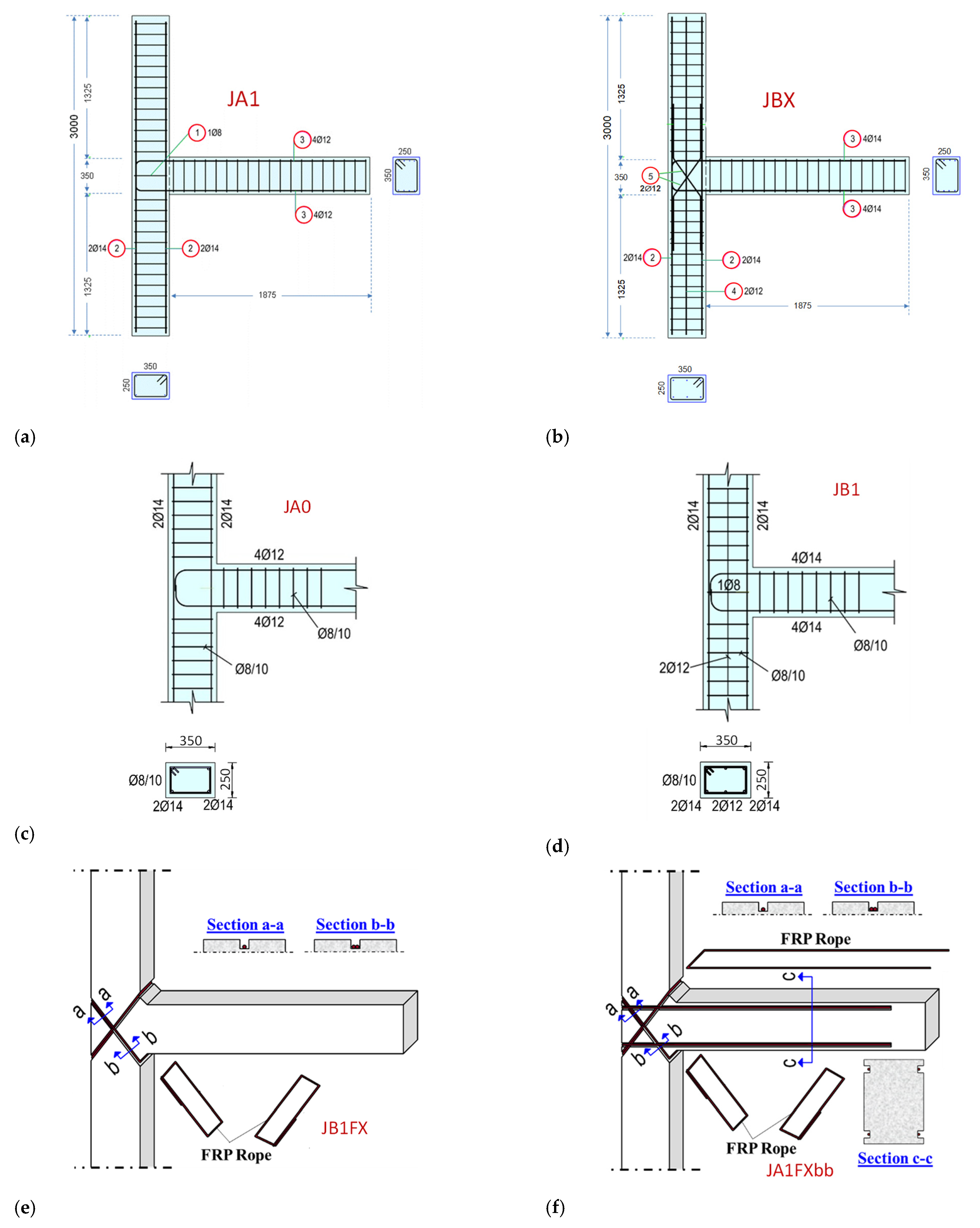
2.3. Group A Specimens

Group A comprises 4 specimens; two specimens of group A, specimens JA0 and JA1 are the reference specimens whereas the other two specimens (JA0F2x2b and JA1F2x2b) have been strengthened with C-FRP ropes diagonally placed as external superficial reinforcement for the strengthening of the joint.
Specimens of group A have been designed in the way that the damage is mainly expected to be located in the beam and not within the joint body (capacity design of frames). They represent common cases of existing structures that have to be strengthened for a reason. The adopted strengthening scheme has been chosen to improve the strength and ductility of the beam-column joint as a whole. The purpose of group A specimens is to experimentally study the efficacy of the use of ropes as external reinforcement to strengthen exterior beam-column connections designed to withstand seismic actions without significant damage in the joint body.

2.4. Group B Specimens

Group B comprises 5 specimens (Table 1); specimens JB0 and JB1 are the reference ones and JB1Fx and JB2F2x2b have been strengthened with C-FRP ropes. Specimen JBX (Figure 1b) has been constructed with steel bars diagonally (X-type) placed in the joint body as shear reinforcement of the beam-column joint. Comparing the shear deformations of specimen JBX with the shear deformations of specimen JB0, useful conclusions about the effectiveness of the X-type reinforcement as shear reinforcement of the joint is evaluated.
In order to investigate the efficacy of the use of the ropes as external strengthening technique for substandard joints the group B specimens have been designed in the way that cracks and some damages are expected to develop in the joint body.
The maximum shear force enforced in the joint by the 4 bars (14 mm diameter) of the tensile reinforcement of the beam is Vjhd = 320 kN and therefrom the shear stress is τ = 3.67 MPa. Further, it is calculated that for the specimens holds ΣMc/MRb = 1.43. According to ACI 318 external joints have to satisfy the relationship ΣMc/MRb > 1.40. Thereunder cracks are expected in the beam but since ΣMc/MRb = 1.43 is almost equal to the critical value 1.40 cracks and damage are also expected in the joint body.

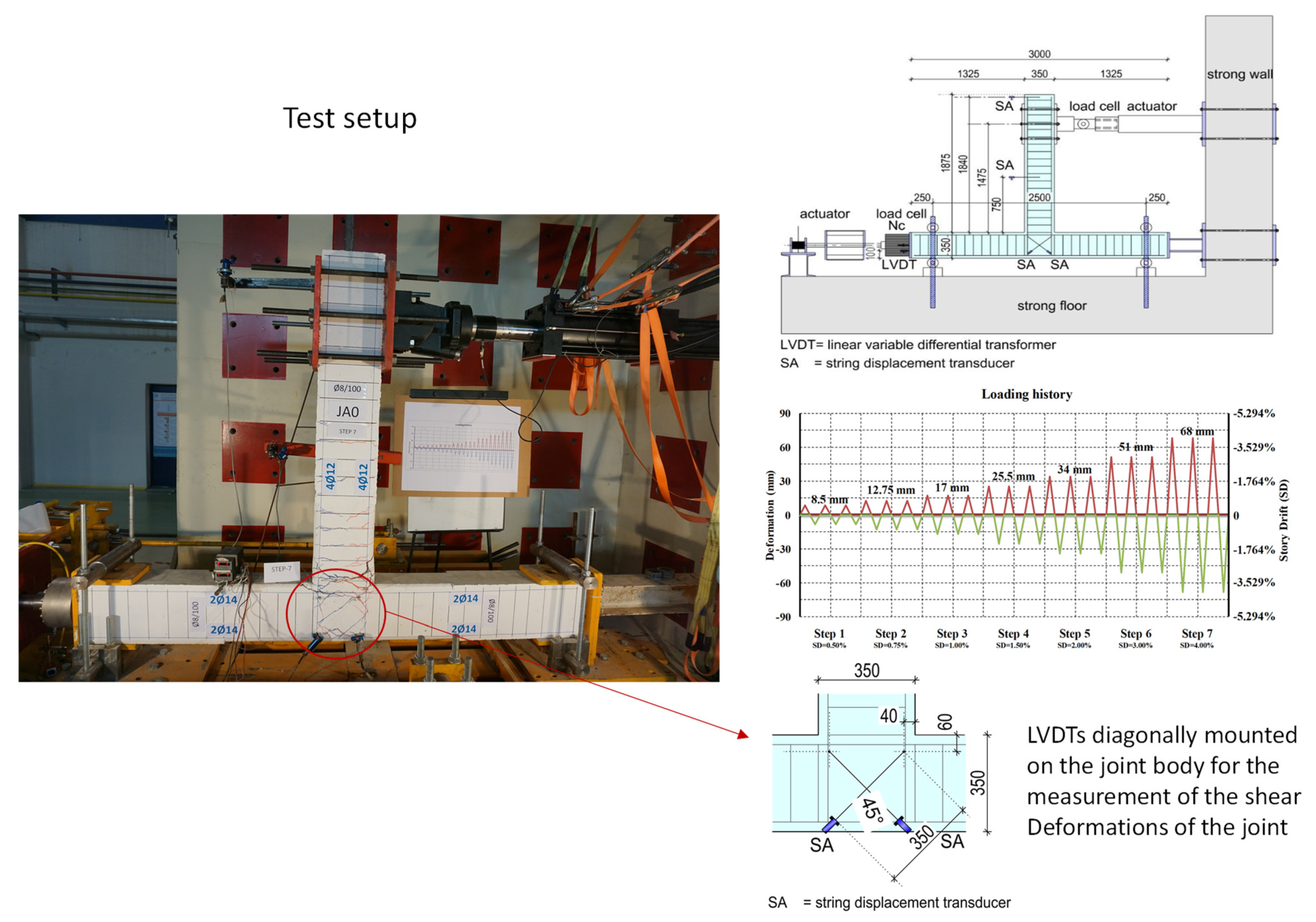
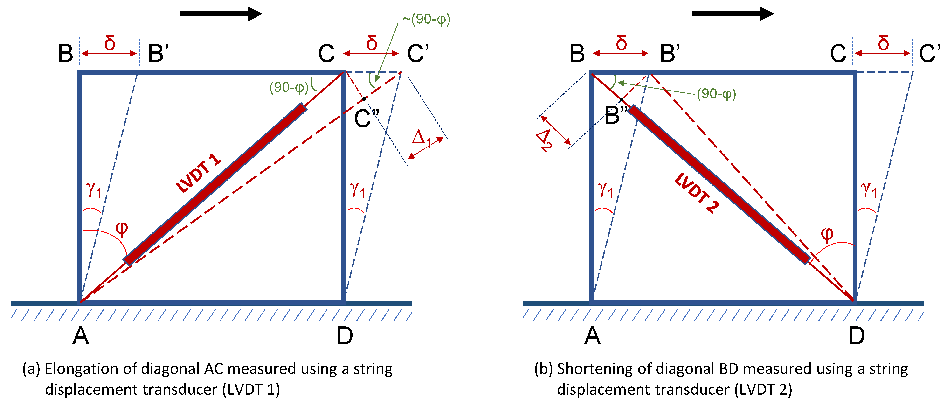
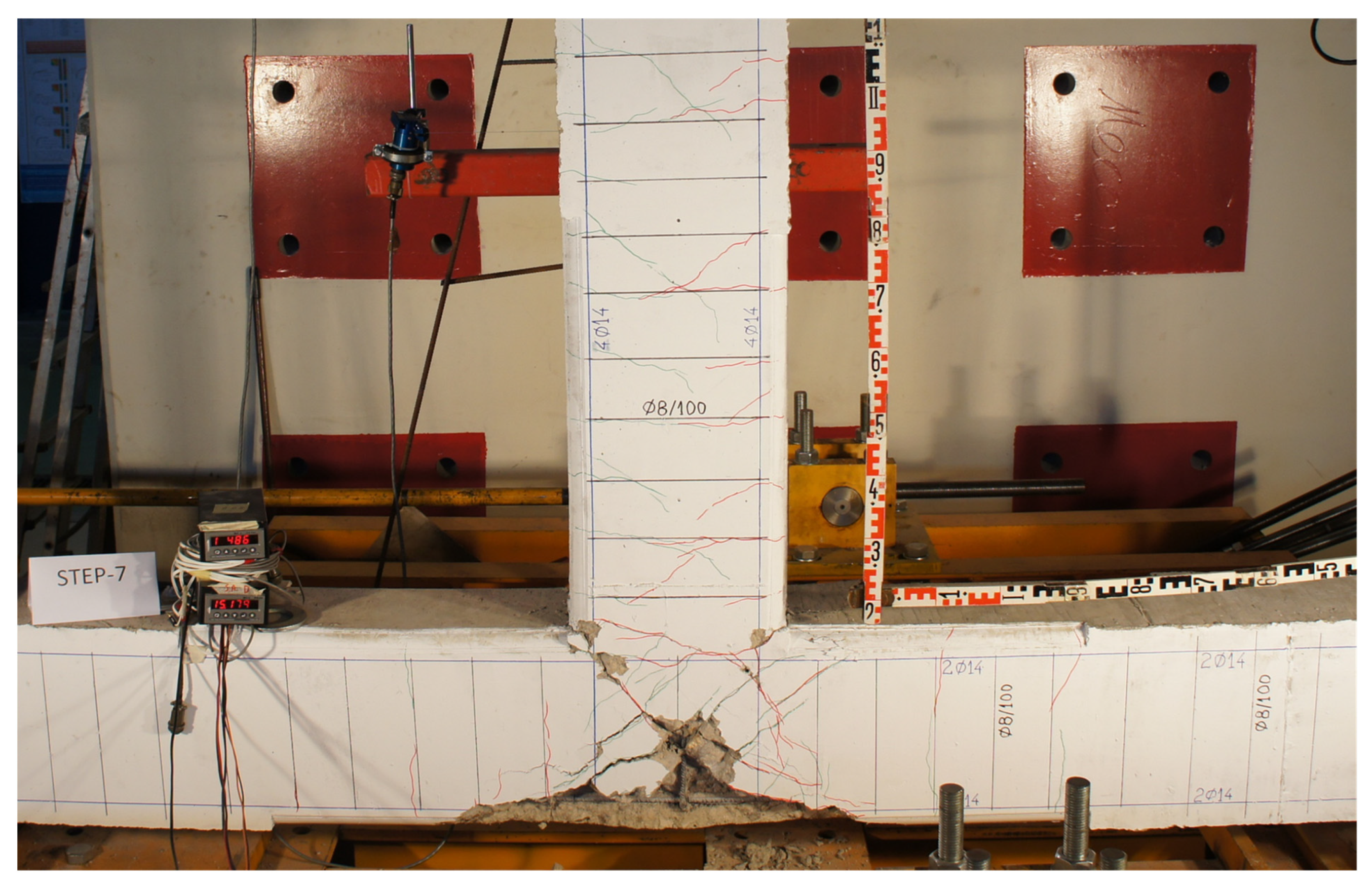
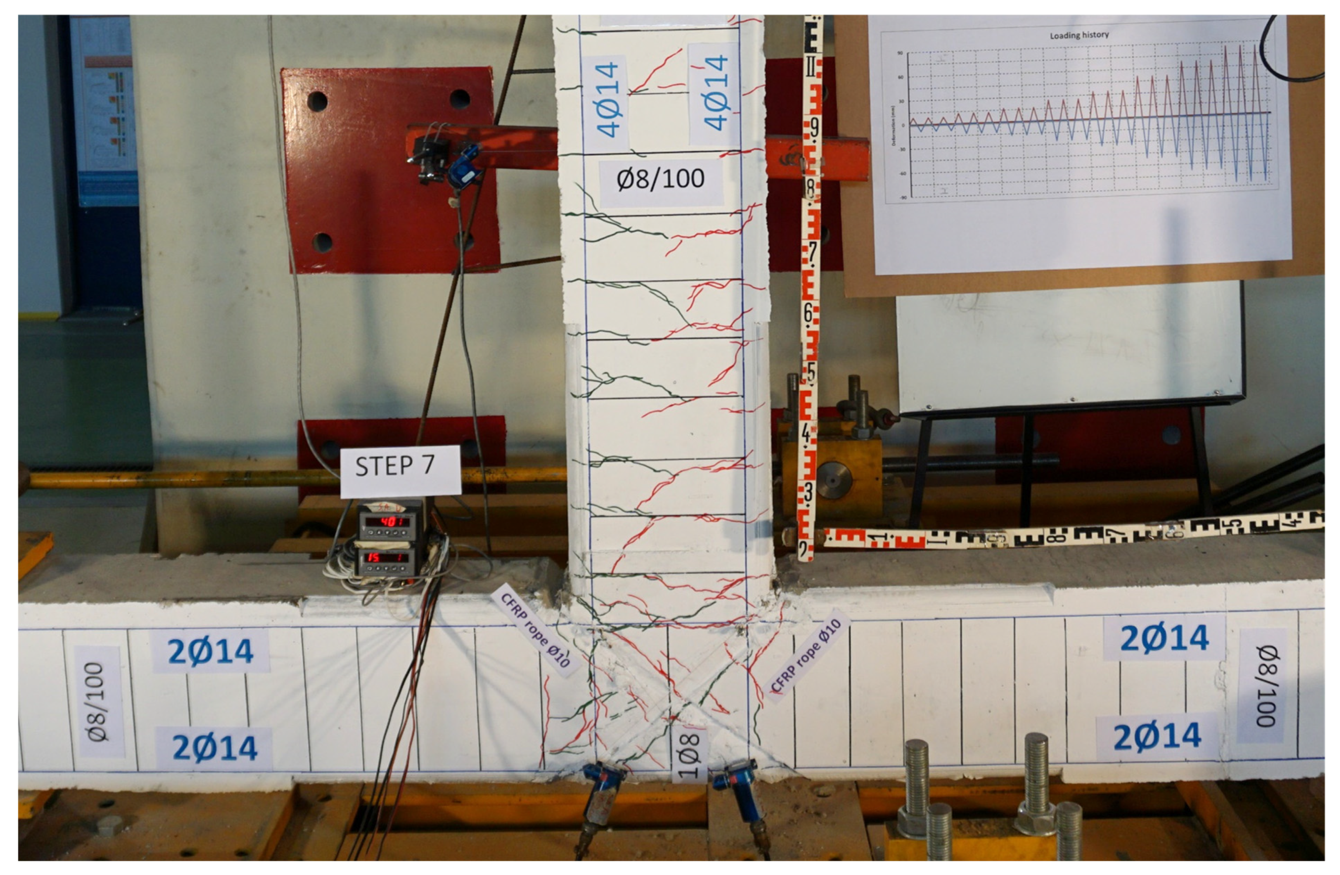
3. Test Setup and Measurement of Shear Deformations

Test setup and the applied loading history are presented in Figure 2 [26,27]. Deformations of the specimen are presented in terms of Story Drift (SD). In general, the term drift represents the ratio between the imposed displacement and the beam length from the loaded end to the column centerline [27,34,35]. In the tested specimens drift is calculated based on the observed deformation Δℓ at each loading step as follows:
Δℓ/(ℓb + hc/2)= Δℓ/(1.525 + 0.35/2) = Δℓ/1700 mm
Shear deformations of the joint body of the beam-column connections are measured using two string LVDTs externally mounted on the joint panel. These LVDTs are diagonally placed in order to record the elongation and the shortening of the diagonals of the orthogonal joint panel at each step of the loading as it can be observed in Figure 3a,b.
The developing shear deformations due to seismic actions of the joint body of a beam-column connection is a valuable measure that indicates the cracking and microcracking state of the material and hence the level of the developing damage. This measure is very useful for the evaluation of the efficiency of strengthening techniques applied for the improvement of the beam-column response to seismic actions.
The joint shear deformation is estimated from the diagonal shortening (Δ2 in Figure 3b) and the diagonal elongation (Δ1 in Figure 3a) of joint body as measured using two string displacement transducers diagonally mounted on the joint panel.
From the elongation Δ1 of diagonal AC as measured by LVDT1 (Figure 3a) the shear deformation is extracted. It is equal to γ1 = δ/h1 where h1 = L1cosφ1 and L1 is the length of the diagonal string LVDT1, and from the orthogonal triangle CC′C″ it can be deduced that
Δ = Δ1/cos(90 − φ1) = Δ1/sinφ1
Thus, it is deduced that
γ1 = (Δ1/sinφ1)/(L1cosφ1) = Δ1/(sinφ1cosφ1) = 2Δ1/sin2φ1
Similarly, from the shortening Δ2 of the diagonal BD and the orthogonal triangle BB′B″ it can be yielded that
γ2 = 2Δ2/sin2φ2
From the rectangular shape of the geometry of the joint panel of the specimens it can be accepted that L1 is more or less equal to L2 and φ1 ≈ φ2.
In this case let L = L1 = L2 and φ = φ1 = φ2, hence the average value of the shear deformation γavg in rad can be approximately expressed as
γ avg = γ 1 + γ 2 2 γ avg = Δ 1 + Δ 2 L sin 2 φ

4. Test Results and Evaluation

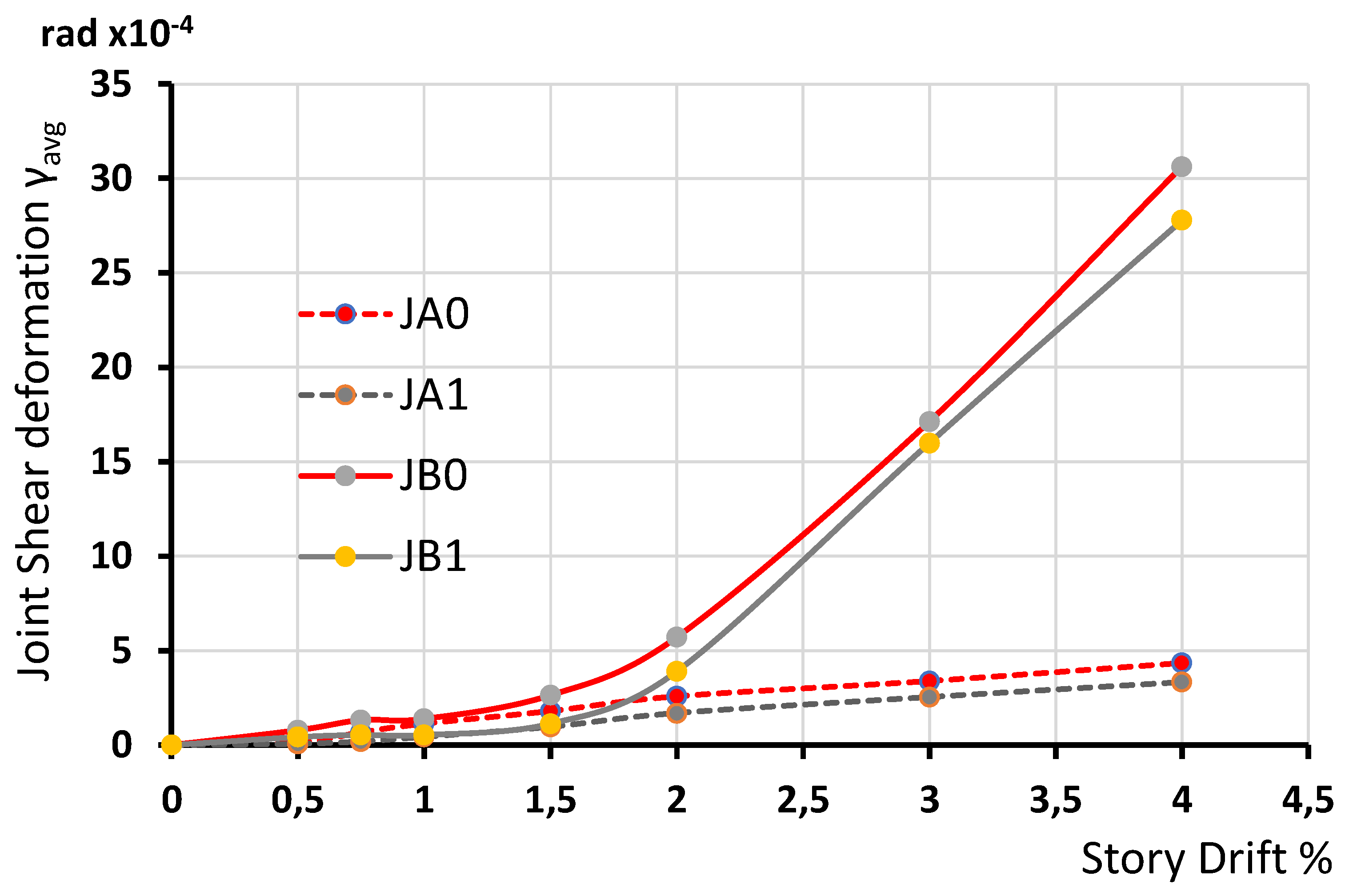
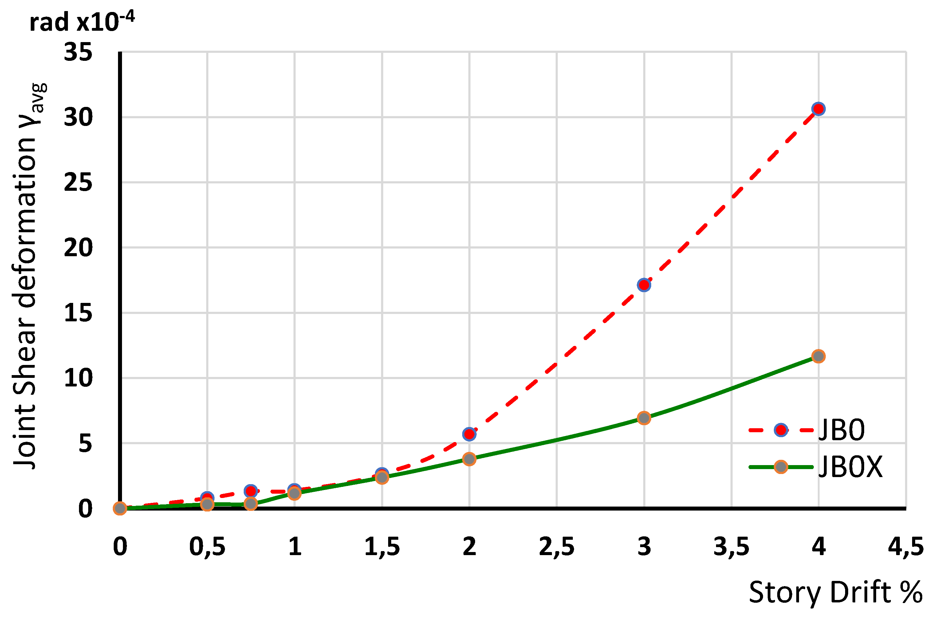
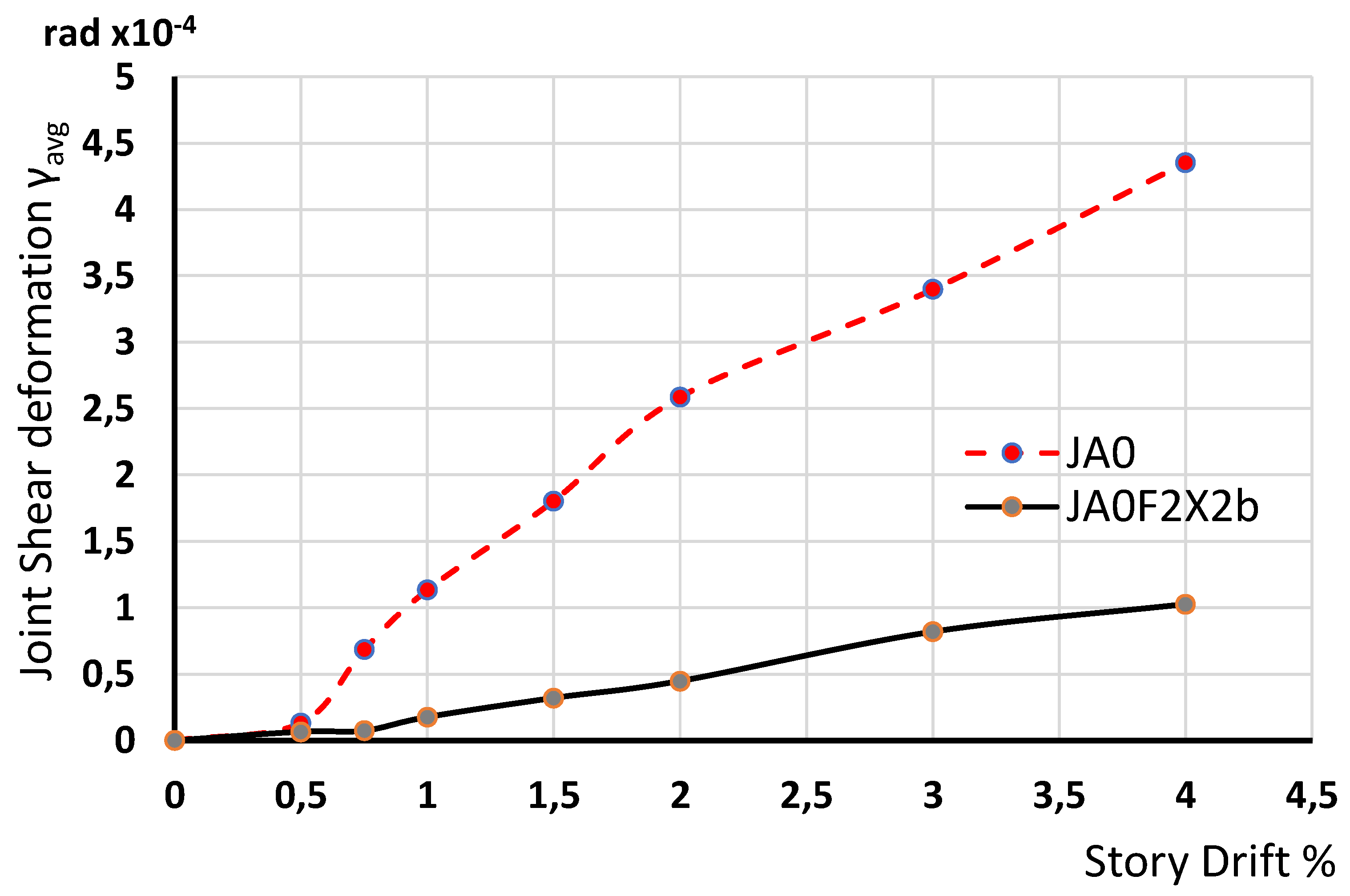
4.1. Shear Deformations—Comparative Presentation and Remarks

The maximum absolute values of the joint shear deformations have been calculated using relationships 1–4 and based on the observed tested measurements of shortening and elongation of diagonals of the joint panel recorded by the diagonal two string LVDTs (Figure 3). Comparative presentations of the shear deformations of the tested specimens are presented in Figure 4, Figure 5, Figure 6, Figure 7 and Figure 8.
Figure 4 presents a comparative examination of the observed shear deformations for specimens JA0, JA1, JB0 and JB1. Specimens JB0 and JB1 exhibited higher values of shear deformations as expected since cracking system in these cases developed in the joint body and the beam. In group A specimens (JA0 and JA1) cracks and damages are located only in the beam and consequently shear deformations of the joint body remained low even in high story drifts.
In Figure 5 the influence of the X-shaped steel reinforcement of the joint (specimen JB0X) on the shear deformations of the joint is studied. Comparative presentation of the observed joint shear deformations of specimens JB0 and JB0X can be shown in Figure 5. The strong influence of the X-shape steel reinforcement placed in the joint body of the specimen JB0X is apparent. In high story drifts (2–4%) the diagonal steel reinforcement kept the joint body intact and efficiently reduced the shear deformations compared to the shear deformations developed in reference specimen JB0 without the diagonal steel reinforcement.
In Figure 6 the influence of the C-FRP ropes externally mounted at both sides of the joint body of the specimen JB1Fx on the shear deformations of the joint panel is examined. The shear deformations of specimen JB1Fx are compared to the ones of the reference specimen JB1. Specimen JB1 has the same characteristics with specimen JB1Fx but the C-FRP ropes. From the comparative presentation (Table 2 and Figure 6) of the observed joint shear deformations of specimens JB1 and JB1Fx it can be observed that the X-form C-FRP cords substantially improved the behavior of the joint in specimen JB1Fx. In fact the ratios of the measured shear deformations of the strengthened specimen JBIFX over the shear deformations of the reference unstrengthened specimen JB1 were 0.77, 0.25, 0.13 and 0.28 for drifts 1.5%, 2.0, 3.0 and 4.0, respectively. Thereupon, it can be observed that in high story drifts (2–4%) the externally mounted C-FRP cords kept the joint body of specimen JB1Fx almost intact (Figure 8 and Figure 9) and efficiently reduced the shear deformations.
Comparative presentation of the observed joint shear deformations of specimens JB1 with specimen JB2F2X2b is presented in Figure 9. Thereupon, the ratios of the measured shear deformations of the strengthened specimen JB2F2X2b over the shear deformations of the reference unstrengthened specimen JB1 were 0.18, 0.17, 0.24 and 0.24 for the drifts 1.5%, 2.0, 3.0 and 4.0, respectively. In this case the externally mounted C-FRP ropes kept the joint body and part of the beam of JB2F2X2b almost intact throughout the testing procedure and efficiently reduced the shear deformations.
Comparative presentation of the observed joint shear deformations of specimens JA0 and JA0F2X2b is shown in Figure 10. Both specimens belong to group A and in both cases the joint body remained intact during the test. Nevertheless, even in this comparison it is observed (Figure 10) that the externally mounted C-FRP ropes of specimen JA0F2x2b substantially reduced the shear deformations.

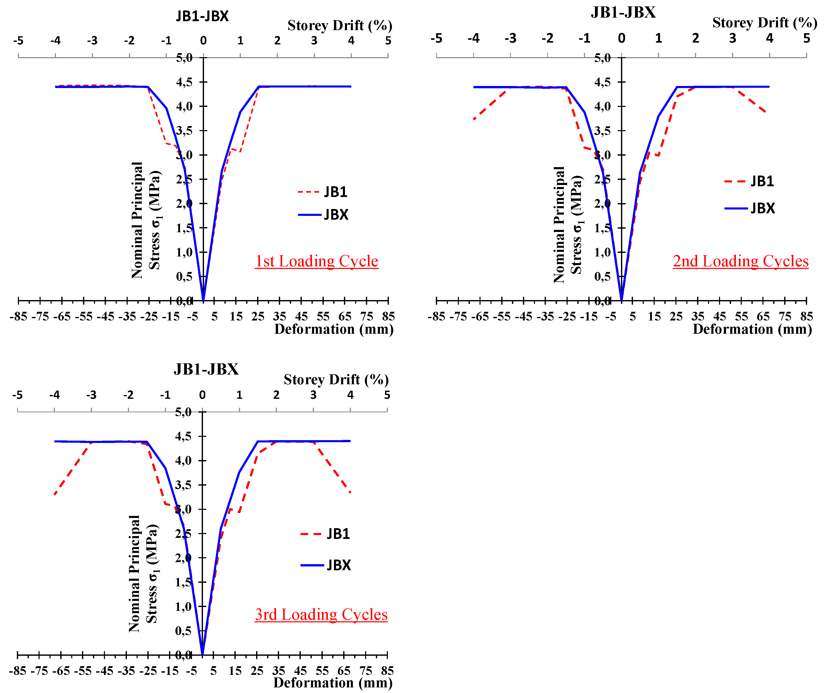
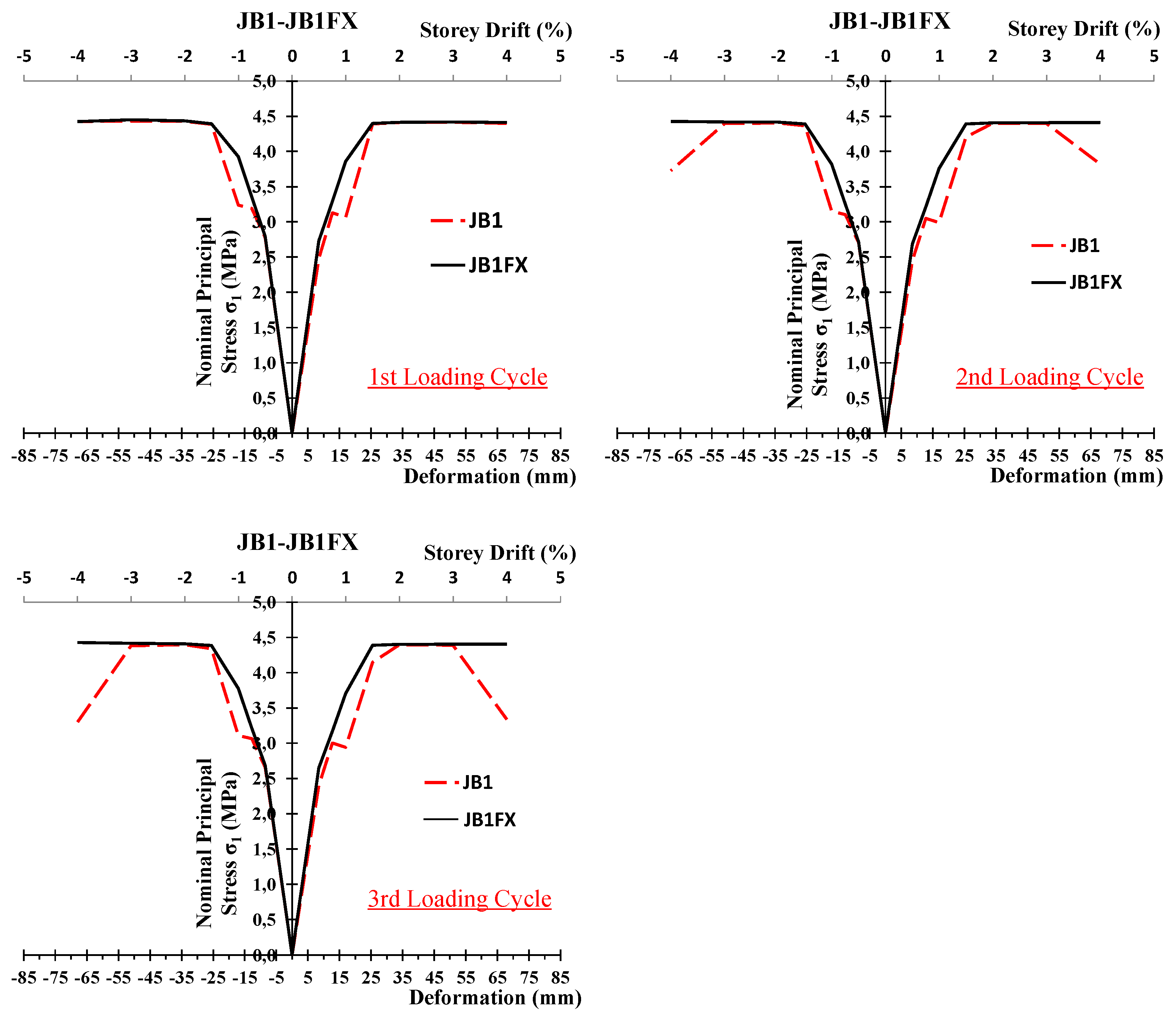
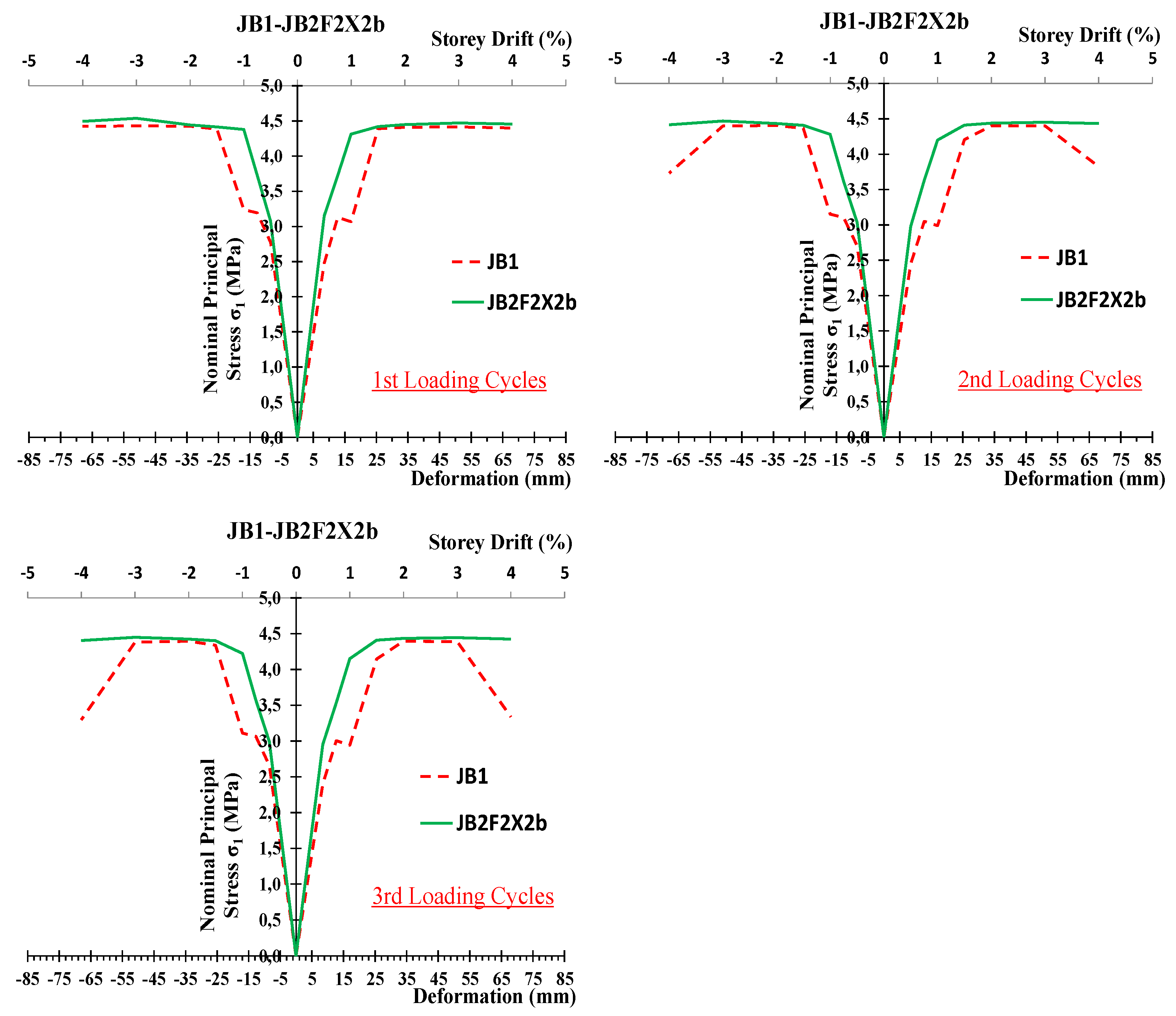
4.2. Principal Stresses—Comparative Presentation and Remarks

The influence of the X-type steel reinforcement placed inside the joint body of specimen JBX on the behaviour of the specimen is examined in terms of the developing principal stresses at each drift step of the testing procedure [26,27,36,37]. Furthermore, the influence of the externally mounted X-shaped C-FRP ropes on the joint body of the specimens JBFX and JB2F2x2b on the behaviour of these specimens in terms of the developing principal tensile stresses inside the joint body at each drift step of the testing procedure is also examined herein.
The principal stresses are calculated based on the normal stress σp and the shear stress τ developing in the joint body at each step of the testing procedure according to the relationships
σ 1 , 2 = σ p 2   σ p 4 + τ 2
where
σ p = N c + P A col     and   τ = V j h / ( b c h c )
Nc is axial force acting on the column of the specimen, P the loading force imposed by the load cell actuator (Figure 2), Vij the shear induced in the beam-column body through the beam and bc, hc the dimensions of the column cross-section.
The values of the principal stresses characterize the damage state of the specimen as a whole. During the testing high values of the principal stresses at a loading step indicated a low level of damage at this level of loading. Furthermore, in case the damage is located in the joint body (and not at the beam) the principal stresses characterize the damage level in the joint body. High principal stresses indicate low damage level in the joint at the specific loading step.
Comparative presentation of the developed principal stresses of specimens JBX, JBFX and JB2F2X2b with the principal stresses of the reference specimen JB1 are presented in Figure 11, Figure 12 and Figure 13.
In Figure 11 the principal stresses of specimen JBX developed during the 1st, 2nd and 3rd loading cycle of each loading step are compared with the corresponding ones of reference specimen JB1. The influence of the X-shape steel reinforcement placed in the joint body proved to be vital. In 2nd and 3rd loading cycles and especially in high story drifts (3–4%) this reinforcement kept the joint body intact and the values of the principal stresses remained high.
In Figure 12 the principal stresses of specimen JB1FX developed during the 1st, 2nd and 3rd loading cycle of each loading step are compared with the corresponding ones of reference specimen JB1. The influence of the X-shape C-FRP ropes mounted on both sides of the joint body proved to be very important. In 2nd and 3rd loading cycles and especially in high story drifts (3–4%) the values of the principal stresses of specimen JB1FX remained high compared to the ones of reference specimen JB1 indicating that the external strengthening C-FRP ropes kept the joint body of the JB1FX intact whereas the joint body of the JB1 severely damaged.
Finally, in Figure 13 the principal stresses of specimen JB2F2X2b developed during the 1st, 2nd and 3rd loading cycle of each loading step are presented. These stresses are compared with the corresponding ones of the unstrengthened reference specimen JB1. The influence of the X-shape C-FRP ropes mounted on both sides of the joint body and the beam proved to be very important. In 2nd and 3rd loading cycles and especially in high story drifts (3–4%) the external strengthening reinforcement kept the joint body almost intact and the values of the principal stresses remained high compared to the ones of reference specimen JB1. These observations indicate that the externally applied strengthening C-FRP ropes kept the joint body of the JB2F2X2b intact whereas the joint body of the JB1 severely damaged.

5. Concluding Remarks

The effectiveness of the innovative strengthening technique of beam-column joints with externally applied C-FRP ropes is examined in terms of the developing shear deformations of the joint body and the study of the tensile principal stresses. The technique is fast and easy to apply whereas the structure’s original dimensions and geometry remains unchanged. Further, the structure’s mass does not change significantly and therefore the dynamic characteristics also remain the same. Nine full scale beam-column joints tested in cyclic loading and the measured shear deformations of their joint body are elaborated and presented in this work. The following concluding remarks have been drawn:
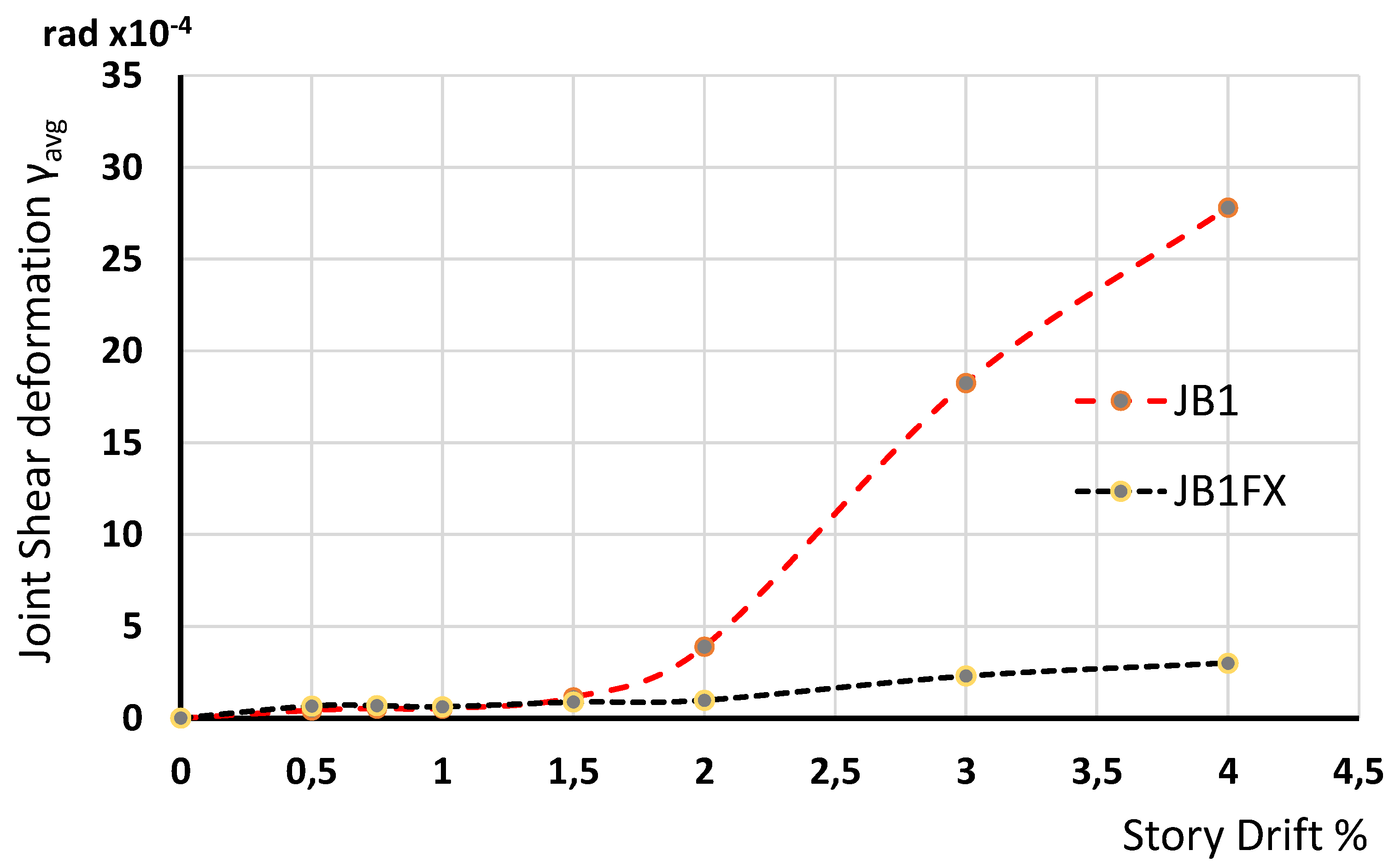
  • From the comparative presentation of the observed joint shear deformations of specimens JB1 and JB1Fx it can be observed that the X-form C-FRP cords substantially improved the behavior of the joint in specimen JB1Fx. The ratios of the measured shear deformations of the strengthened specimen JBIFX over the shear deformations of the reference unstrengthened specimen JB1 were 0.13–0.28 for high story drifts (2.0–4.0). Thereupon, it can be observed that the externally mounted C-FRP cords kept the joint body of specimen JB1Fx almost intact and efficiently reduced the shear deformations.
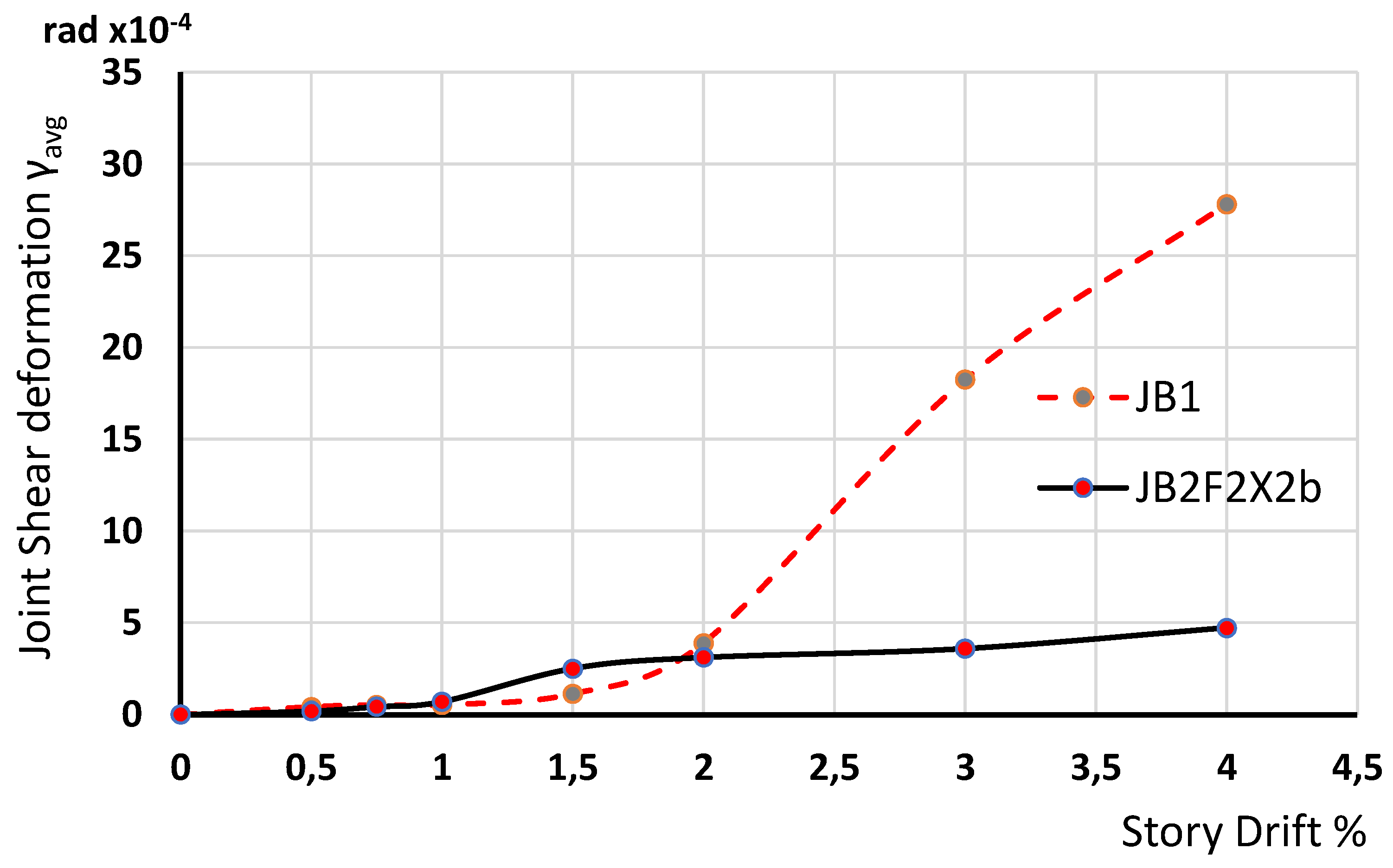
  • Systematic and extended comparative presentations of the shear deformation of specimens with and without ropes proved in all the examined cases that the externally mounted C-FRP ropes kept the joint body almost intact and substantially reduced the shear deformations especially in high drifts. Thus, it can be concluded that the application of the C-FRP ropes for the strengthening of beam—column connections either designed according to modern codes or deficient ones proved to be an efficient and easy to apply technique.
  • Moreover, the influence of the externally mounted X-shaped C-FRP ropes on the seismic behaviour of these specimens has been also examined in terms of the developing principal tensile stresses inside the joint body. From the comparisons of the principal stresses developing in specimens with X-form C-FRP ropes to the reference specimen JB1 it has been yielded that in all the examined cases the ropes kept the joint body intact and allowed the development of higher values of principal stresses comparing to the stresses developing in specimen JB1 without ropes where the joint body severely damaged.

Author Contributions

Conceptualization, C.K.; methodology, E.G.; software, G.I.K.; validation, C.K. and E.G.; investigation, E.G. and G.I.K.; data curation, E.G.; writing—review and editing, C.K.; visualization, G.I.K.; project administration, C.K.; funding acquisition, E.G. All authors have read and agreed to the published version of the manuscript.

Funding

The presented research received no external funding.

Institutional Review Board Statement

Not applicable.

Informed Consent Statement

Not applicable.

Data Availability Statement

Data available on request.

Acknowledgments

We would like to thank the company SIKA HELLAS SA for the supply and free disposal of the needed FRP materials.

Conflicts of Interest

The authors declare no conflict of interest.

References

  1. De Risi, M.T.; Del Vecchio, C.; Ricci, P.; Ludovico, M.D.; Prota, A.; Verderame, G.M. Light FRP Strengthening of poorly detailed reinforced concrete exterior beam-column joints. J. Compos. Constr. 2020, 24, 04020014. [Google Scholar] [CrossRef]
  2. Karayannis, C.G.; Sirkelis, G.M. Strengthening and rehabilitation of RC beam-column joints using FRP jacketing and epoxy resin injections. J. Earthq. Eng. Struct. Dyn. 2008, 37, 769–790. [Google Scholar] [CrossRef]
  3. Tsonos, A.G. Ultra-high-performance fiber reinforced concrete: An innovative solution for strengthening old R/C structures and for improving the FRP strengthening method. WIT Trans. Eng. Sci. 2008, 64, 273–284. [Google Scholar] [CrossRef] [Green Version]
  4. Karayannis, C.G.; Golias, E. Fullscale tests of RC joints with minor to moderate damage repaired using C-FRP sheets. Earthq. Struct. 2018, 15, 617–627. [Google Scholar] [CrossRef]
  5. Pohoryles, D.A.; Melo, J.; Rossetto, T.; Varum, H.; Bisby, L. Seismic retrofit schemes with FRP for deficient RC beam-column joints: State-of-the-art review. J. Compos. Constr. 2019, 23, 4. [Google Scholar] [CrossRef] [Green Version]
  6. Murad, Y.; Al Bodur, W.; Ashteyat, A. Seismic retrofitting of severely damaged RC connections made with recycled concrete using CFRP sheets. Front. Struct. Civ. Eng. 2020, 14, 554–568. [Google Scholar] [CrossRef]
  7. Tafsirojjaman, T.; Fawzia, S.; Thambiratnam, D.P. Structural behaviour of CFRP strengthened beam-column connections under monotonic and cyclic loading. Structures 2021, 33, 2689–2699. [Google Scholar] [CrossRef]
  8. Mostofinejad, D.; Akhlaghi, A. Experimental Investigation of the Efficacy of EBROG Method in Seismic Rehabilitation of Deficient Reinforced Concrete Beam–Column Joints Using CFRP Sheets. J. Compos. Constr. 2017, 21, 04016116. [Google Scholar] [CrossRef]
  9. Mostofinejad, D.; Akhlaghi, A. Flexural strengthening of reinforced concrete beam column joints using innovative anchorage system. ACI Struct. J. 2017, 114, 1603–1614. [Google Scholar] [CrossRef]
  10. Hamzah, M.K.; Rashid, R.S.M.; Hejazi, F. Cyclic performance of exterior RC beam-column strengthened with different thicknesses of CFRP sheets. IOP Conf. Ser. Earth Environ. Sci. 2022, 961, 012069. [Google Scholar] [CrossRef]
  11. Al-Rousan, R.Z.; Sharma, A. Integration of FRP sheet as internal reinforcement in reinforced concrete beam-column joints exposed to sulfate damaged. Structures 2021, 31, 891–908. [Google Scholar] [CrossRef]
  12. Al-Mahmoud, F.; Castel, A.; François, R.; Tourneur, C. Strengthening of RC members with near-surface mounted CFRP rods. Compos. Struct. 2009, 91, 138–147. [Google Scholar] [CrossRef]
  13. Dalfre, G.M.; Barros, J.A.O. NSM technique to increase the load carrying capacity of continuous RC slabs. Eng. Struct. 2013, 56, 137–153. [Google Scholar] [CrossRef] [Green Version]
  14. Alwash, D.; Kalfat, R.; Al-Mahaidi, R.; Du, H. Shear strengthening of RC beams using NSM CFRP bonded using cement based adhesive. Constr. Build. Mater. 2021, 301, 124365. [Google Scholar] [CrossRef]
  15. Murad, Y.Z.; Alseid, B.H. Retrofitting interior RC beam-to-column joints subjected to quasi-static loading using NSM CFRP ropes. Structures 2021, 34, 4158–4168. [Google Scholar] [CrossRef]
  16. MohammadiFirouz, R.; Pereira, E.; Barros, J. Thermo-mechanical Bonding Behaviour of CFRP NSM System Using Cement-Based Adhesive. In Proceedings of the 10th International Conference on FRP Composites in Civil Engineering, Istanbul, Turkey, 8–10 December 2021; Lecture Notes in Civil Engineering. Springer: Cham, Switzerland, 2021; Volume 19, pp. 287–299. [Google Scholar] [CrossRef]
  17. Al-Saadi, N.T.K.; Mohammed, A.; Al-Mahaidi, R.; Sanjayan, J. A state-of-the-art review: Near-surface mounted FRP composites for reinforced concrete structures. Constr. Build. Mater. 2019, 209, 748–769. [Google Scholar] [CrossRef]
  18. Marchisella, A.; Muciaccia, G.; Sharma, A.; Eligehausen, R. Experimental investigation of 3d RC exterior joint retrofitted with fully-fastened-haunch-retrofit-solution. Eng. Struct. 2021, 239, 112206. [Google Scholar] [CrossRef]
  19. Yu, F.; Feng, C.; Fang, Y.; Liu, Q.; Hu, Y.; Bu, S. Experimental study on low-strength concrete joint core strengthened with steel meshes for connecting PFCC column and RC beam. Adv. Struct. Eng. 2021, 24, 797–814. [Google Scholar] [CrossRef]
  20. Ruiz-Pinilla, J.G.; Cladera, A.; Pallares, F.J.; Calderon, P.A.; Adam, J.M. Joint strengthening by external bars on RC beam-column joints. J. Build. Eng. 2022, 45, 103445. [Google Scholar] [CrossRef]
  21. Ebanesar, A.; Gladston, H.; Noroozinejad Farsangi, E.; Sharma, S.V. Strengthening of RC beam-column joints using steel plate with shear connectors: Experimental investigation. Structures 2022, 35, 1138–1150. [Google Scholar] [CrossRef]
  22. Araby, Z.; Abdullah, A.; Affifuddih, M. Analysis of reinforced concrete beam-column joint structures retrofitting. IOP Conf. Ser. Mater. Sci. Eng. 2020, 933, 012037. [Google Scholar] [CrossRef]
  23. Al-Rousan, R.Z.; Alkhawaldeh, A. Numerical simulation of the influence of bond strength degradation on the behavior of reinforced concrete beam-column joints externally strengthened with FRP sheets. Case Stud. Constr. Mater. 2021, 15, e00567. [Google Scholar] [CrossRef]
  24. Golias, E.; Zapris, A.G.; Kytinou, V.K.; Kalogeropoulos, G.I.; Chalioris, C.E.; Karayannis, C.G. Effectiveness of the novel rehabilitation method of seismically damaged rc joints using c-frp ropes and comparison with widely applied method using c-frp sheets—experimental investigation. Sustainability 2021, 13, 6454. [Google Scholar] [CrossRef]
  25. Chalioris, C.E.; Kosmidou, P.-M.K.; Papadopoulos, N.A. Investigation of a new strengthening technique for RC deep beams using carbon FRP ropes as transverse reinforcements. Fibers 2018, 6, 52. [Google Scholar] [CrossRef] [Green Version]
  26. Karayannis, C.G.; Golias, E. Full-scale experimental testing of RC beam-column joints strengthened using CFRP ropes as external reinforcement. Eng. Struct. 2022, 250, 113305. [Google Scholar] [CrossRef]
  27. Karayannis, C.G.; Golias, E. Strengthening of deficient RC joints with diagonally placed C-FRP ropes. Earthq. Struct. 2021, 20, 123–132. [Google Scholar] [CrossRef]
  28. Rashmi, M.; Anand, V.N.; Balaji, N.C. Shear strengthening of RC beams using near surface mounted technique with glass fiber reinforced polymer. AIP Conf. Proc. 2021, 2327, 020012. [Google Scholar] [CrossRef]
  29. De Lorenzis, L.; Teng, J.G. Near-surface mounted FRP reinforcement: An emerging technique for strengthening structures. Compos. Part B Eng. 2007, 38, 119–143. [Google Scholar] [CrossRef]
  30. Tsonos, A.G. A model for the evaluation of the beam-column joint ultimate strength—A more simplified version. Earthq. Struct. 2019, 16, 141–148. [Google Scholar] [CrossRef]
  31. Tsonos, A.G. An innovative solution for strengthening of old R/C structures and for improving the FRP strengthening method. Struct. Monit. Maint. 2014, 1, 323–338. [Google Scholar] [CrossRef]
  32. Kalogeropoulos, G.I.; Tsonos, A.-D.G.; Konstandinidis, D.; Tsetines, S. Pre-Earthquake and Post-Earthquake Retrofitting of Poorly Detailed Exterior RC Beam-to-Column Joints. Eng. Struct. 2016, 109, 1–15. [Google Scholar] [CrossRef]
  33. Tsonos, A.G. Effectiveness of CFRP jackets in post-earthquake and pre-earthquake retrofitting of beam-column subassemblages. Struct. Eng. Mech. 2007, 27, 393–408. [Google Scholar] [CrossRef]
  34. Verderame, G.M.; De Risi, M.T.; Ricci, P. Experimental investigation of exterior unreinforced beam-column joints with plain and deformed bars. J. Earthq. Eng. 2016, 22, 404–434. [Google Scholar] [CrossRef]
  35. Bonacci, J.F.; Wight, J.K. Displacement-based assessment of reinforced concrete frames in earthquakes. ACI Spec. Publ. 1996, 162, 117–138. [Google Scholar]
  36. Golias, E.; Zapris, A.G.; Kytinou, V.K.; Osman, M.; Koumtzis, M.; Siapera, D.; Chalioris, C.E.; Karayannis, C.G. Application of X-shaped CFRP ropes for Structural Upgrading of Reinforced Concrete Beam-Column Joints under Cyclic Loading—Experimental Study. Fibers 2021, 9, 42. [Google Scholar] [CrossRef]
  37. Golias, E.; Lindenthal, H.; Franz-Hermann Schlüter, F.H.; Karabinis, A. Ertüchtigung seismisch beschädigter Rahmenknoten aus Stahlbeton mittels FRP-Filamentbündelverbindungen. Bautechnik 2020, 97, 268–278. [Google Scholar] [CrossRef]
Figure 1. Geometry and steel reinforcement for the specimens (dimensions in mm): (a) JA1, (b) JBX, (c) JA0, (d) JB1, (e) JB1FX, (f) JA1FXb.
Fibers 10 00028 g001
Figure 2. Test setup and instrumentation for the measurement of shear deformation of the joint body of the tested specimens.
Fibers 10 00028 g002
Figure 3. Measurement of the shortening (a) and the elongation (b) of the diagonals of the joint body using two string LVDTs diagonally mounted on the joint panel.
Fibers 10 00028 g003
Figure 4. Comparative presentation of the observed joint shear deformations of specimens JA0, JA1, JB0 and JB1. Group B specimens (solid lines) exhibited higher values of shear deformations as expected since cracking system and damages are located in the joint body and the beam. On the contrary in group A specimens the cracks and damages are located in the beam only; therefore, shear deformations of the joint body remained low even in high story drifts.
Fibers 10 00028 g004
Figure 5. Comparative presentation of the observed joint shear deformations of specimens JB0 and JB0X. The influence of the X-shape steel reinforcement placed in the joint body of the specimen JB0X is apparent. In high story drifts (2–4%) X steel reinforcement kept the joint body intact and efficiently reduced the shear deformations.
Fibers 10 00028 g005
Figure 6. Comparative presentation of the observed joint shear deformations of specimens JB1 and JB1FX. The influence of the X-form C-FRP ropes external mounted on the joint body of the specimen JB1FX is apparent. In high story drifts (2–4%) the externally mounted C-FRP ropes kept the joint body intact and efficiently reduced the shear deformations.
Fibers 10 00028 g006
Figure 7. Comparative presentation of the observed joint shear deformations of specimens JB1 and JB2F2X2b. In high story drifts (2–4%) the externally mounted C-FRP ropes kept the joint body intact and efficiently reduced the shear deformations.
Fibers 10 00028 g007
Figure 8. Specimen JB1 after the testing. The main damage has been located in the joint body.
Fibers 10 00028 g008
Figure 9. Specimen JB1FX after the testing. CFRP ropes have been applied diagonally on the joint body forming external X-shape reinforcement. Cracks mainly appear at the beam and very few at the joint body. The joint body remained almost intact after the loading.
Fibers 10 00028 g009
Figure 10. Comparative presentation of the observed joint shear deformations of specimens JA0 and JA0F2X2b. The specimens belong to group A and in both cases the joint body remained intact. Nevertheless, even in this comparison it is observed that the externally mounted C-FRP reduced the shear deformations.
Fibers 10 00028 g010
Figure 11. Principal stresses developing in the joint body of specimen JB1X during the testing are presented and compared to the ones of the reference specimen JB1.
Fibers 10 00028 g011
Figure 12. Principal stresses developing in the joint body of specimen JB1FX during the testing are presented and compared to the ones of the reference specimen JB1.
Fibers 10 00028 g012
Figure 13. Principal stresses developing in the joint body of specimen JB2F2X2b during the testing are presented and compared to the ones of the reference specimen JB1.
Fibers 10 00028 g013
Table 1. Reinforcements of beam-column specimens.
ReinforcementsJA0JA0F2x2bJA1JA1F2x2bJB0JB1JBXJB1FxJB2F2x2b
Fibers 10 00028 i001--1Ø81Ø8-1Ø81Ø81Ø82Ø8
Fibers 10 00028 i0022Ø142Ø142Ø142Ø142Ø142Ø142Ø142Ø142Ø14
Fibers 10 00028 i0034Ø124Ø124Ø124Ø124Ø144Ø144Ø144Ø144Ø14
Fibers 10 00028 i004-2Ø12-2Ø122Ø122Ø122Ø12-2Ø12
Fibers 10 00028 i005------2Ø12--
FRP ropes
of joint
-X-type Double rope-X-type Double rope---X-type Single ropeX-type
Double rope
FRP ropes
of beam
-Double rope-Double rope----Double rope
Table 2. Measured shear deformations γavg of specimens JB1 and JB1FX.
Shear Deformations γavg rad × 10−4
DriftJB1JB1FX
1.51.1390.875
2.03.8990.981
3.018.2622.291
4.027.7977.902
Publisher’s Note: MDPI stays neutral with regard to jurisdictional claims in published maps and institutional affiliations.

