Article

Performance of Steel Bar Lap Splices at the Base of Seismic Resistant Reinforced Concrete Columns Retrofitted with FRPs—3D Finite Element Analysis

by
Evgenia Anagnostou
and
Theodoros Rousakis
*
Department of Civil Engineering, Democritus University of Thrace, 67100 Xanthi, Greece
*
Author to whom correspondence should be addressed.
Fibers 2022, 10(12), 107; https://doi.org/10.3390/fib10120107
Submission received: 13 October 2022 / Revised: 29 November 2022 / Accepted: 6 December 2022 / Published: 14 December 2022
(This article belongs to the Collection Feature Papers in Fibers)

Abstract

:
This paper examines analytically the design criteria for the composite retrofit of reinforced concrete (RC) columns with a short lap splice length of steel rebars inside the critical region. The advanced potential of pseudo-dynamic three-dimensional (3D) finite element (FE) modelling is utilized to investigate critical design parameters for the required carbon fiber-reinforced polymer (FRP) jacketing of RC columns with a rectangular cross-section based on the experimental lateral force-to-drift envelope behavior of characteristic cases from the international literature. The satisfactory analytical reproduction of the experimental results allows for the systematic numerical investigation of the developed stress along the lap splice length. The maximum lateral force and the horizontal displacement ductility of the column, as well as the maximum developed tensile axial force on the longitudinal bars, their variation along the lap, the bar yielding, and the plastic hinge length variation, are considered to determine the seismic behavior of the columns. For the first time, cases of smooth bar slip together with delayed bar yielding or without bar yielding are identified that may be recorded through a “ductile” P-d seismic response. Such pseudo-ductile response cases are revisited through suitably revised redesign criteria for adequate FRP jacketing.

1. Introduction

Existing earthquake-prone columns in RC brick wall-infilled framed structures often need to be repaired or strengthened together with the suitable modification of infills [1,2,3,4,5,6,7] in order to meet modern seismic and energy retrofit requirements. RC columns designed according to early code provisions may suffer detrimental damage during strong seismic excitations, as in many cases the corresponding ductility demands or detailing of reinforcement are inadequate.
A widespread technique to strengthen RC columns is the external application of advanced composite jacketing. Axially loaded concrete specimens, with or without internal steel reinforcement, have been used to investigate the confinement effect of external bonded composite materials (with an organic or inorganic matrix) [8,9,10,11,12,13,14,15]. They suggest that the use of such techniques leads to the increase of lateral pressure on the member and therefore to the increase of axial compressive strength and axial strain ductility of the concrete.
Furthermore, to estimate the effectiveness of FRP confinement on RC columns under seismic loading, numerous experimental tests have been carried out that subjected the foundation of half RC columns to a constant top axial load and imposed top cyclic horizontal displacements. Among the numerous parameters under investigation, columns with square and rectangular cross-sections with lap-spliced longitudinal steel bars [16,17,18,19,20,21,22,23,24,25,26,27,28,29,30,31,32,33,34,35,36,37,38,39] within the critical region are included. Such columns are usually met in existing structures, and when the lap splice length is inadequate, an elastic or inelastic relative slip of the longitudinal bars may limit the shear strength and/or the horizontal deformation capacity.
The available experimental investigations have led to the proposal of equations for calculating the chord rotation at failure (θu) of the columns. Modern codes for seismic design and interventions, such as Eurocode 8 part 3 (EC8.3) [40] and Greek Retrofit Code (KANEPE) [41], have adopted such equations. The extensive investigation of the recent experimental and analytical database by Anagnostou et al. [42] (see also [43]) for 261 columns with or without lap splices suggests that the existing design models for RC columns of square or rectangular sections, with or without FRP confinement, provide the predicted shear strength compared against the experimental one, with an average absolute error (AAE) of about 20%. Further, the same study reveals that the AAE of the predicted chord rotation at failure was higher than 35% (for both codes). Therefore, besides the recent research focusing on the effects of external confinement with composites on the seismic behavior of columns [44,45,46], including their deformation capacity [47,48] and the plastic hinge length [49,50,51], further research is necessary to address the unidentified gaps in our knowledge.
Finite element (FE) analyses may provide the suitable analytical framework to improve our understanding, better assess the effects of different design parameters, and identify missing ones in different RC applications [52,53,54,55,56,57,58,59,60,61,62,63]. Three-dimensional (3D) pseudo-dynamic FE inelastic analyses with advanced material models may help with analytically investigating the interactions among different materials, as well as the internal reinforcements and external retrofits [64,65,66,67]. Such advanced analyses may provide critical missing parameters to enrich existing analytical databases through a hybrid experimental-analytical approach to propose improved design models (see its application in RC beams strengthened with FRPs in shear in Rousakis et al. [68] and in FRP-confined RC columns under axial concentric load in [69]). In RC columns with lap-spliced bars and an external FRP retrofit that are subjected to seismic loading, a similar approach is necessary to address the varying bars’ lap-splice performance.
This study utilizes several characteristic published seismic experiments of columns with lap-spliced longitudinal bars [16,17,18,19,20,21,22,23,24,25,26,27,28,29,30,31,32,33,34,35,36,37,38,39], which were retrofitted with FRPs based on earlier investigations of all available experiments and design models in the field of seismic-resistant FRP retrofits ([48,70], among others). Then, these carefully chosen columns were modelled and analyzed pseudo-dynamically with 3D finite elements (FEs). The variable performance of bar lap splices at the base of the columns was thoroughly investigated. The maximum developed tensile axial force on the longitudinal bars, their variation along the lap, the bar yielding, and the plastic hinge length variation were considered to determine the seismic behavior of the columns. The FE analysis-derived missing variables enrich the developed databases. The abovementioned systematic hybrid approach is utilized for the first time to propose more reliable design models for the prediction of the chord rotation at failure of columns with lap spliced bars and external FRP confinement. For the first time, cases of smooth bar slip together with delayed bar yielding or without bar yielding are identified that may be recorded through a “rather ductile” P-d seismic response. Such pseudo-ductile response cases are revisited through suitably revised redesign criteria for adequate FRP jacketing.

2. Experimental Database

An experimental database has been created by the authors that includes 261 large-scale RC column specimens with a square or rectangular cross-section. All columns were loaded with a constant (or zero) axial compressive load and subjected to cycles of increasing lateral displacements, simulating pseudo-seismic loading [16,17,18,19,20,21,22,23,24,25,26,27,28,29,30,31,32,33,34,35,36,37,38,71,72,73,74,75,76,77,78,79,80,81,82,83,84,85,86,87,88,89,90,91,92,93,94,95,96,97,98,99,100]. The columns are sorted according to those with or without seismic-related damage and with or without FRP confinement. The database gathers the geometrical and mechanical characteristics of these columns, as well as the experimental values of maximum lateral force (VR or Pmax) and chord rotation at failure (θu). In addition, the yield and ultimate chord rotation, the yield curvature, the yield moment, and the shear strength of the columns are calculated according to EC8.3 [40] and KANEPE [41].
In order to compare the analytical and numerical values to the experimental ones, the Average Ratio, AR, of the analytical-to-experimental values (Equation (1)) and the Average Absolute Error, AAE (Equation (2)), are utilized.
A R = 1 n · i = 1 n ( x a n a l ) i ( x e x p ) i
A A Ε = 1 n · i = 1 n | ( x a n a l ) i ( x e x p ) i | ( x e x p ) i · 100 ,
In the above equations, xanal is the analytical value and xexp is the experimental value of the parameter (e.g., θu, VR). It should be noticed that values of AR close to 1 and values of AAE close to 0% indicate accurate predictions of the values under investigation.
In this study, columns with lap splices are further investigated. RC cantilever columns subjected to seismic loading are selected from the study by Bousias et al. [17] in order to investigate the effect of different parameters, such as the lap splice length and the CFRP jacket layers, through advanced FE analyses. The geometry and the material properties, as well as the axial load, of the nine thoroughly selected columns are presented in Table 1. More details on the geometry and the material properties of these specimens, as well as the experimental procedure, can be found in [17].

3. 3D Finite Elements Modelling

The analytical models of the characteristic columns are developed in ANSYS Workbench, Explicit Dynamics. Advanced material models for concrete, steel, and composites are suitably calibrated.

3.1. Materials

The response of a part is determined by the material properties assigned to the part. Material properties, depending on their application, may be linear, non-linear, or temperature-dependent.

3.1.1. Concrete

The Riedel–Hiermaier–Thoma (RHT) [101] plasticity model for brittle materials, which is also suitable for modelling the dynamic loading of concrete, was used. The RHT constitutive model is a combined plasticity and shear damage model which enables the reproduction of monotonic, repeated, or cyclic imposed displacements. The deviatoric stress in the material is limited by a generalized failure surface (Equation (3)) which can be used to represent the aspects of the response of geological materials: pressure hardening, strain hardening, strain rate hardening in tension and compression, third invariant dependence for compressive and tensile meridians, strain softening (shear induced damage), and coupling of damage due to porous collapse.
f ( p , σ e q , θ , ε ˙ ) = σ e q Y T X C ( p ) · F C A P ( p ) · R 3 ( θ ) · F R A T E ( ε ˙ )
The RHT model is suitably calibrated to provide the behavior of concrete under pseudo-seismic loading, as well as the effects of pre-damaged concrete. The values for the compressive strength of concrete for each column are included in Table 1. The material parameters for concrete modeling are presented in Table 2.

3.1.2. Longitudinal and Transverse Steel Bars

The elastic-plastic behavior of the steel bars (longitudinal and transverse) and the strain hardening of the material after yield strength were simulated using the multilinear isotropic hardening model, a plasticity model usually used in large strain analysis. The multilinear hardening behavior is described by a piece-wise linear stress—total strain curve, starting at the origin and defined by sets of positive stress and strain values, according to the information provided by the experimental tests. The first stress-strain point corresponds to the yield stress. Subsequent points define the elastic-plastic response of the material. In addition, the Young’s modulus of steel was considered equal to 200 GPa and Poisson’s ratio equal to 0.3. The steel material parameters of the model are presented in Table 3. The impactor (steel plate) is modelled as a purely elastic material.

3.1.3. Fiber Reinforced Polymer Jacket
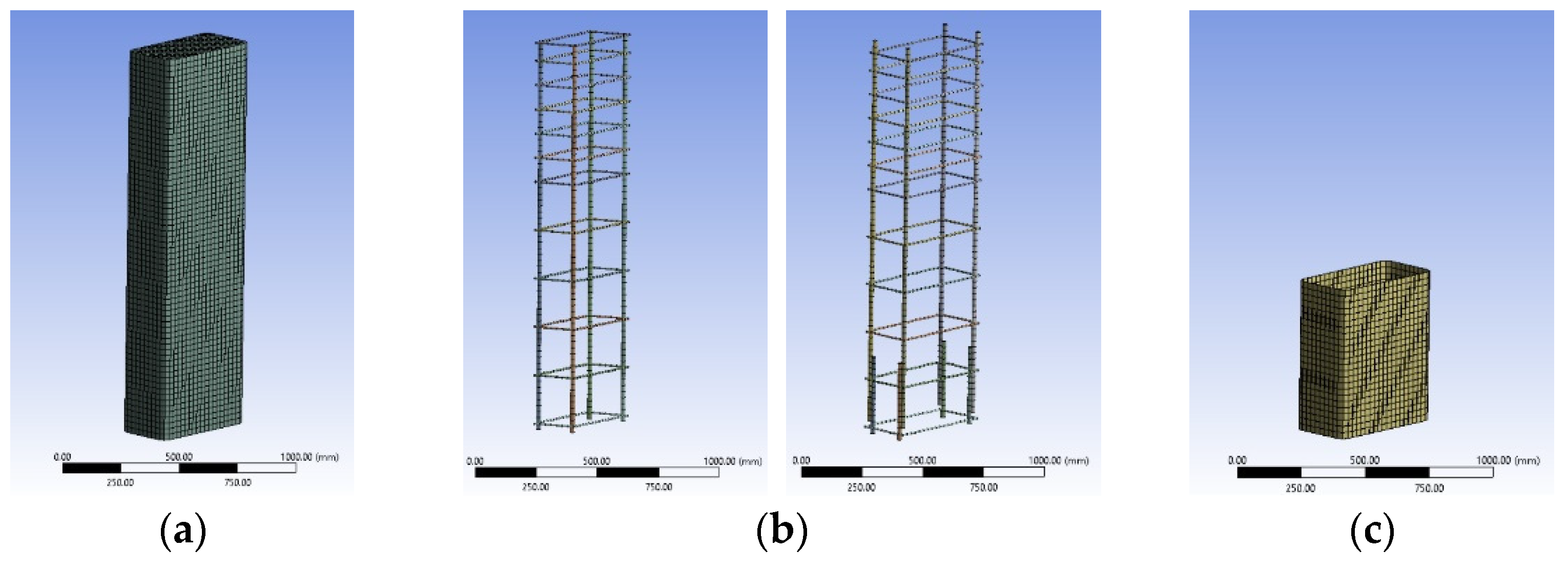
The elastic behavior of the FRP jacket was simulated with the orthotropic elasticity model. For elastic modulus of the carbon fibers alone of 230 GPa per fiber layer thickness, the elastic modulus was considered to be 59.16 GPa to include the properties of the impregnation epoxy resin. The thickness of the jacket was suitably increased to account for the combined fiber and resin thickness per layer (with a similar axial rigidity value for fiber thickness multiplied by the fiber modulus of elasticity or for combined thickness multiplied by the modulus of elasticity of the fiber-resin jacket). This approach provides more reliable stress-strain behavior and the local fracture of the FRP jacket. Table 4 presents the material parameters of CFRP used for the orthotropic elasticity model.

3.2. Geometry

The geometry of the RC columns was accurately reproduced. The models consist of different parts of solid body for the concrete, the FRP jacket, and the impactor. Line bodies were used for the longitudinal and transverse reinforcements (Figure 1).

3.3. Connections

The interaction between the different parts of the FE model need to be defined for an accurate prediction of the behavior and failure mode of the member [102,103,104,105]. In the context of the present numerical study, the contact region between concrete and FRP was defined as “bonded” for all columns and no sliding or separation between faces or edges was allowed. This approach is in line with other analytical research work [60,106], and is supported by the experimental evidence [9,12]. No slip was observed during RC column tests confined with FRP jackets. In cases where the fracture of the concrete core occured at the neighboring area, this was captured by the advanced concrete model. For all bodies, the body interaction type was defined as “frictionless” if it activated frictionless sliding contact between any exterior node or face of the selected bodies. In addition, all elements of the line bodies (internal steel reinforcement), which are contained within any solid body (concrete) in the model, are defined to be converted to discrete reinforcement (using the “reinforcement” body interaction type, typically used for RC applications).

3.4. Mesh

Explicit mesh was followed to form an accurate 3D grid. The solid bodies for concrete and the CFRP jacket were modelled with eight-node hexahedral elements (element type Hex8). They are well suited to transient dynamic applications including large deformations, large strains, large rotations, and complex contact conditions. The line bodies for steel bars and stirrups were modelled with 2-node line elements that allow for large displacements and the resultant elasto-plastic response.
Regarding the element size, as it gets smaller, more divisions are generated, and the accuracy is improved. However, a greater number of elements are created, and the required time for one analysis becomes unprofitable for the large-scale model of an RC column. Based on the mesh convergence study conducted by the authors, a mesh size of 25 mm (for all individual parts of the model) was chosen as the most favorable to provide satisfactory accuracy regarding the seismic behavior of RC columns at an acceptable analysis time.

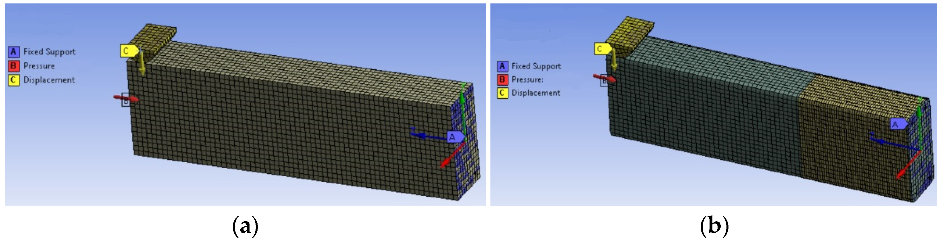
3.5. Boundary Conditions and Loading

The cantilever column specimens were fix-supported at the base. A constant pressure was exerted on the top section, reproducing the constant axial load during the experimental test (the values for normalized axial load, v, are included in Table 1). After the application of the axial load, an increasing horizontal displacement (monotonic loading) was imposed at the steel impactor (Figure 2). The monotonic response (pseudo-dynamic analysis) can serve as a rather reliable envelope force-to-deformation curve of the cyclic one and thus save valuable computational time. Therefore, the 3D FE analyses were performed by imposing an increasing horizontal displacement.

4. Numerical Results and Discussion

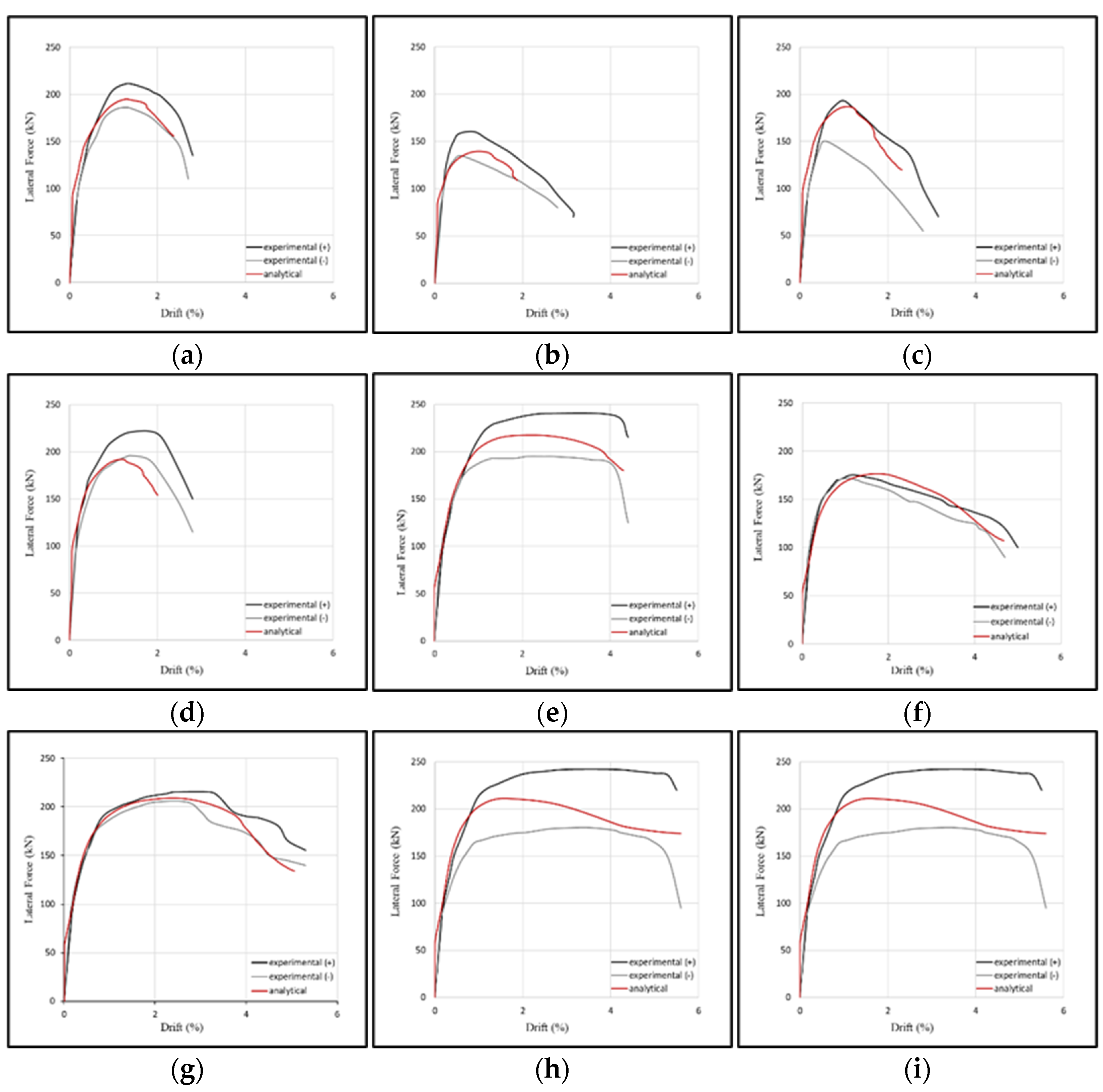
4.1. Lateral Force-to-Drift (%) Curves

The numerical lateral force-to-drift (P-θ) curves of columns R-0L0, R-0L1, R-0L3, R-0L4, R-P2L0, R-P2L1, R-P2L3, R-P2L4, and R-P5L3 are presented against the experimental ones in Figure 3.
The displacement and load at ultimate were considered at the fracture of the steel reinforcement, at the failure of concrete under compression, at the fracture of the FRP jacket (not local), or when the limit lateral bearing load reached 80% of the maximum one (KANEPE, EC8.3).
The numerical and experimental results of all columns for the maximum and ultimate lateral force (Pmax, Pu) and the ultimate displacements (δPu) are presented and compared in Table 5. The experimental results refer to the average values of the two directions, push and pull.
The divergence between the experimental and numerical values of loads at maximum and ultimate, as well as of displacements at ultimate (based on the experimental load at ultimate or the experimental displacement), is low. Therefore, the analytical results can be further elaborated to draw reliable conclusions for the mechanical behavior of RC columns with lap-spliced longitudinal bars. Based on the unique features of the concrete material model, the developed 3D FE columns may be utilized to investigate the effects of steel corrosion or the preloading of columns as well.

4.2. Analytical Response of the Longitudinal Bars

The maximum axial tensile force of the bars throughout the loading, as well as the variation of the axial force (or of the stress) along the lap splice, are examined.

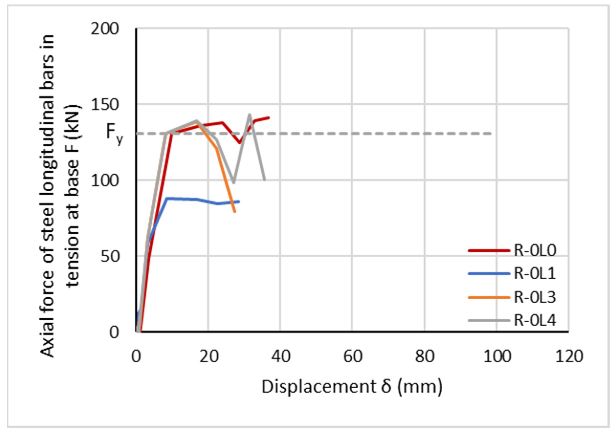
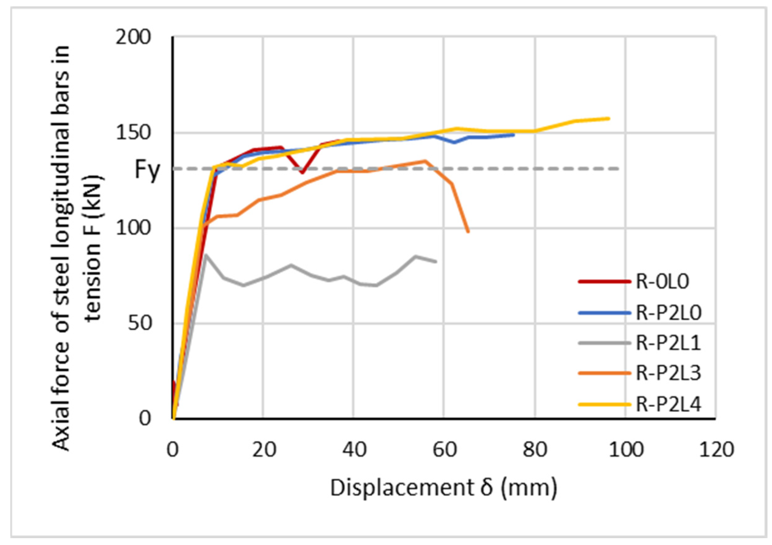
4.2.1. Axial Force of Longitudinal Bars at the Base of Column

The axial force developed on the longitudinal bars in tension at the base of the column, Fmax (or the developed stress, fs), is provided. The comparative curves of the tensile axial force of the bar versus the horizontal displacement of the columns (F-δ curves) without FRP confinement are depicted in Figure 4.
The analyses suggest that the axial force developed on the bars in tension at the lap region at the base of column (Fmax) of unretrofitted column without lap splices (R-0L0) is 145.94 kN at a displacement of 37.80 mm (at ultimate or failure), higher than the analytical yield force Fy = 130.8 kN. The presence of inadequate lap splices with 15 dbL length at the base of an unretrofitted RC column results in the decrease of Fmax by 40% in column R-0L1 (Fmax = 87.95 kN at 8.57 mm, lower than the analytical yield force Fy = 130.8 kN), 5% in column R-0L3 (Fmax = 138.33 kN at 16.64 mm), and 2% in column R-0L4 (Fmax = 143.30 kN at 31.36 mm) compared to R-0L0. Both columns with considered adequate lap splice lengths (R-0L3, R-0L4) may face some temporary or detrimental slip after steel bar yielding.
As for the columns externally confined with two layers of FRP (Figure 5), the analyses suggest that the Fmax is 147.89 kN (at 57.78 mm) in column R-P2L0, 85.49kN (at 7.29 mm) in column R-P2L1 (lower than the analytical yield force, Fy = 130.8 kN), 134.63 kN (at 55.90 mm) in column R-P2L3, and 157.42 kN (at 96.27 mm) in column R-P2L4. It is observed that the Fmax-to-displacement curves of R-P2L0 (without lap splices) and R-P2L4 (45 dbL lap splice length) are almost identical (also with R-0L0), confirming that a lap splice length of 45 dbL provides an equivalent tensile bar response (Figure 5). In contrast, the analyses suggest that the Fmax obtained for column R-P2L1 is lower than the Fy, although the column is externally confined with FRPs. The two layers of CFRP jacketing, in this case, are inadequate to prevent the lap-spliced bars from slipping, despite the pseudo-ductile behavior observed in Figure 3f. This pseudo-ductility is attributed to the pseudo-ductile bar contribution (see Figure 5). However, the response of the column is considered to be inadequate, as there is slip and it fails to reach bar yielding. This bar response is similar to the one in R-0L1 (Figure 4). For R-P2L3, the maximum tensile force of the bars exceeds the yield one, but at a horizontal displacement of 40 mm. The column seems to suffer initially by the controlled slip of the bars, starting before the displacement at the yielding of the bars of columns R-0L0 or R-P2L0 (Figure 5). However, at around 60 mm displacement, the bars slip again. The revealed deficient performance of the lap-spliced bars in R-P2L3 is in accordance with the lower bearing horizontal load of around 180–200 kN at the pseudo-yielding point (Figure 3). The corresponding bearing horizontal load for R-P2L0 at real bar yielding is around 190–225 kN (Figure 3).
The above conclusions coincide with observations made based on the experimental results of Bournas & Triantafillou [19]. They tested RC columns with lap-spliced bars (20 dbL = 280 mm = 0.67 lb,min or 40 dbL = 560 mm = 1.29 lb,min) without FRP confinement (L20d_C, L40d_C) or with FRP confinement (L20d_R2, L40d_R2). They provided the steel strain histories of starter bars at the column base during testing, measured with strain-gauges (Figure 6). The lap-splice length equal to 20 dbL is inadequate for developing the yield strain (or yield stress) of the longitudinal bars (εyL = 523/200,000 = 2.62‰), while the slippage of lap-spliced bars is observed. Although a lap-splice length of 40 dbL is adequate to develop the yield stress of the longitudinal bars, it is not sufficient to prevent slippage, which is observed after yielding. The application of two layers of CFRP delays the slippage of the lap-spliced bars for the inadequate lap-splice length of 20 dbL, happening at higher drifts of 3.75%. However, longitudinal bars do not really surpass yielding strain, while this marginal yielding of bars initiates at a higher column drift of 3.44%. As for the adequate lap-splice length of 40 dbL, FRP confinement does not affect the drift at the yielding of the lap-spliced bars, while no slippage is observed at higher drifts up to column failure.
Getting back to the 3D FE analyses, the axial force of the tensile longitudinal bar at the base of the column (F) to the top displacement (δ) curve changes slope when F = Fy (Figure 7a). However, for inadequate lap splice lengths, this change occurs at a lower force (F < Fy). In this case, the axial force is defined as pseudo-yield force (Fpy) and the corresponding displacement as pseudo-yield displacement (δpy), as shown in Figure 7b. This pseudo-ductility or delay in real tensile bar yielding development may explain the divergences in prediction in some cases in the yield flexural moment or chord rotation of the columns with lap-spliced bars, despite the fact that they are more or less affected by the mechanical characteristics of the steel bar under tension. These cases urge an assessment of the performance of such columns as acceptable or not in redesign.

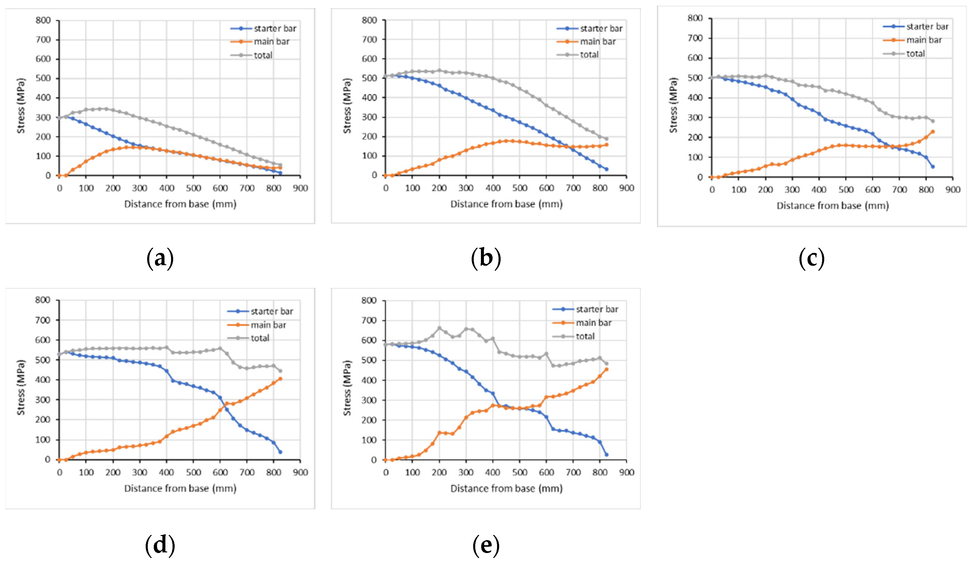
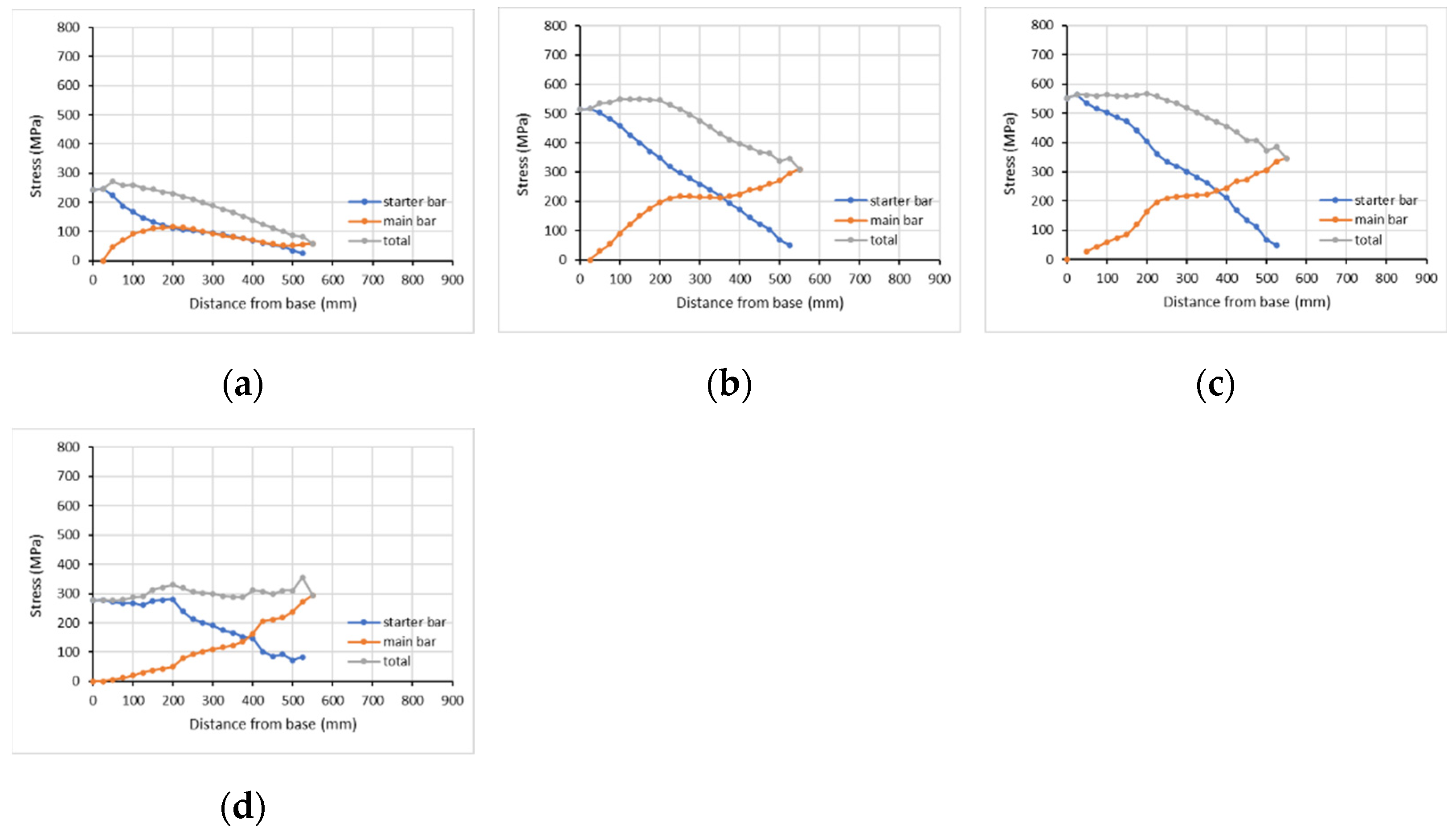
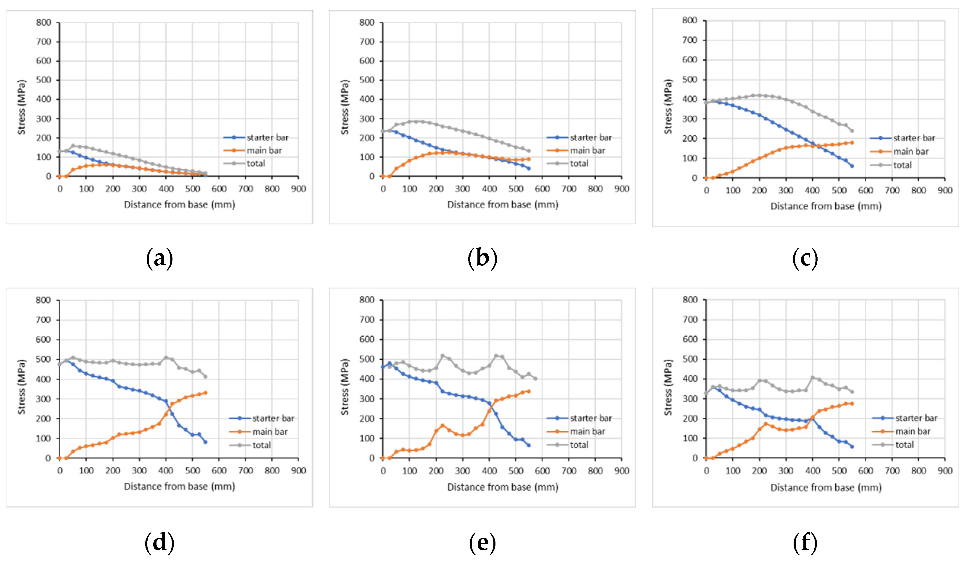
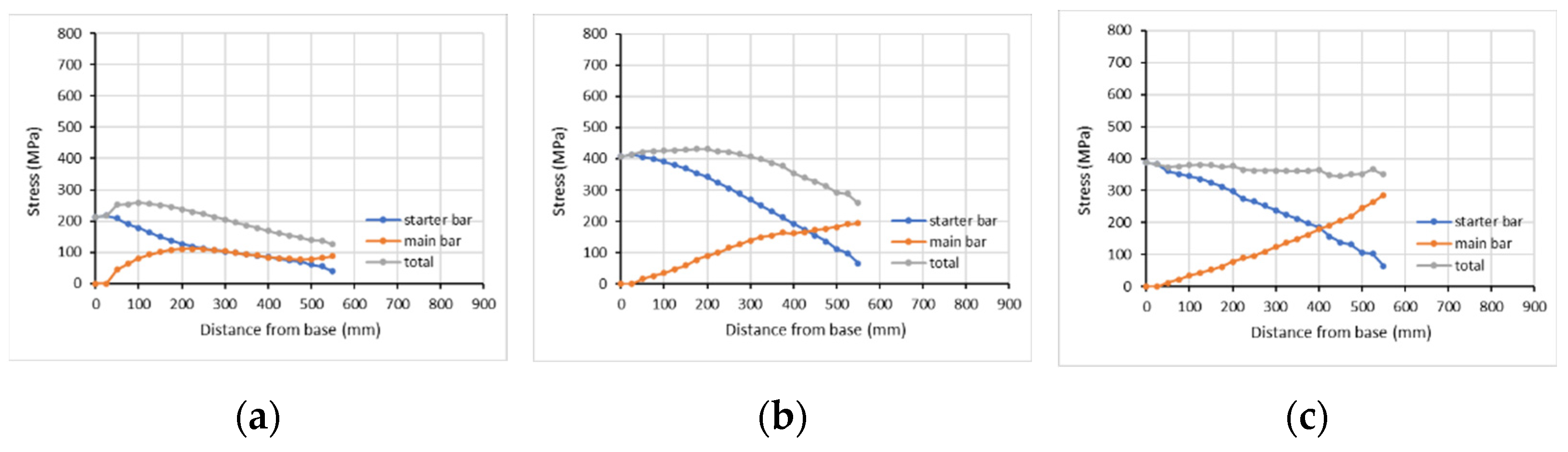
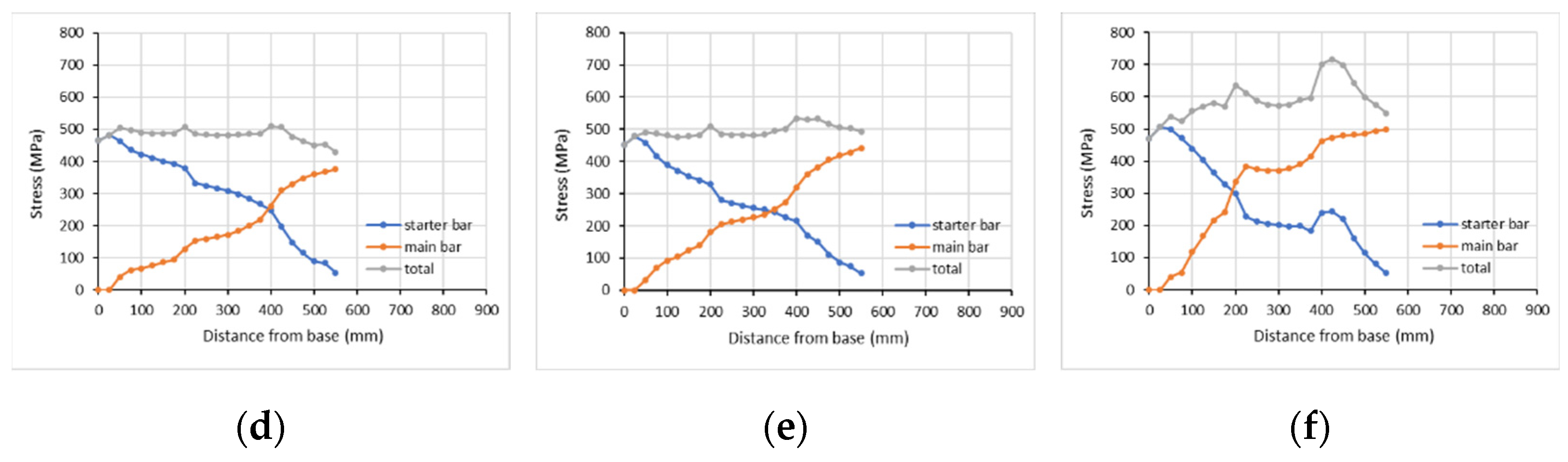
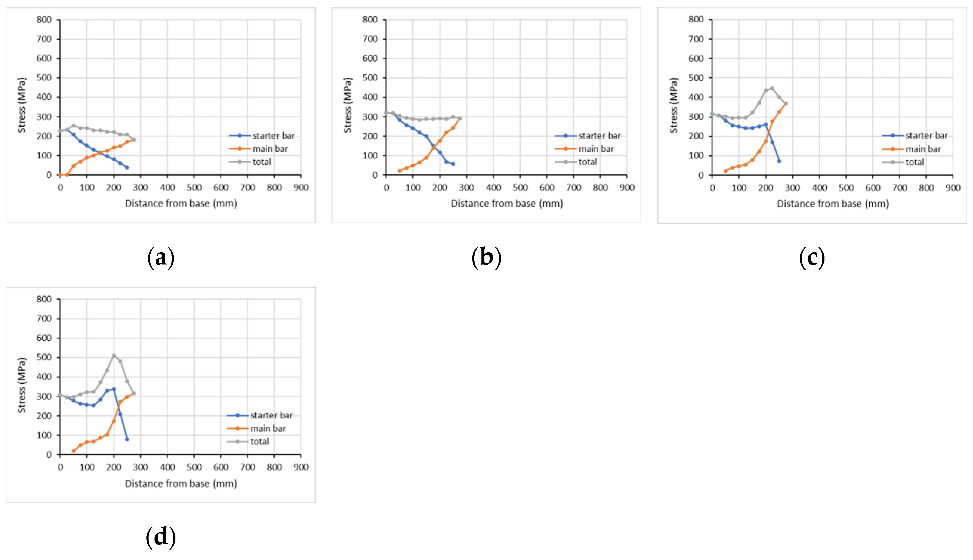
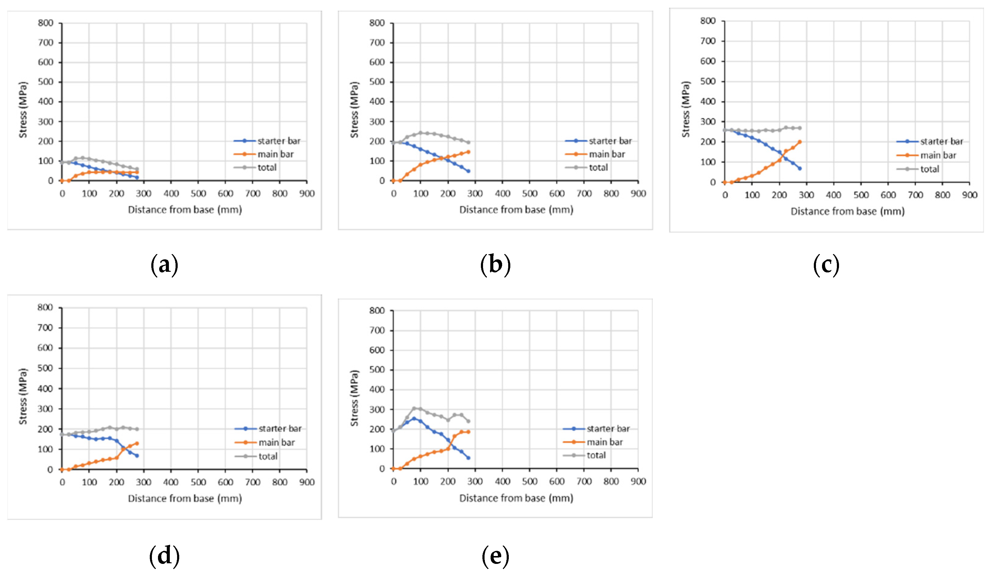
4.2.2. Stress along the Lap Splice Length

Melek et al. [107] carried out experimental tests on six RC columns with short lap splices (20 dbL = 508 mm = 0.78 lb,min). They placed strain gauges to monitor the strain histories of the lap-spliced bars (Figure 8a), which recorded at about 3% lateral drift when most of them were damaged due to the damage to the columns. They expected a triangular strain distribution before bond deterioration (Figure 8b).
Figure 9a,b show the strain distribution of corner and middle bars, respectively, for column S20MI tested by Melek et al. [107]. The yield stress of the longitudinal bars is fyL,main = 510 MPa for the main bars and fyL,starter = 521 MPa for the starter bars. For the starter bars, the strain distribution is triangular indeed (blue), while for the main bars it has a curved form (orange). A different response of the corner and middle longitudinal bars in tension during cyclic loading can also be observed.
The analytical model proposed by Chowdhury & Orakcal [108] (calibrated with the experimental results of Melek et al. [107] research work) for inadequate lap splices (20 dbL = 508 mm = 0.78 lb,min) predicts the increment of stress in both the starter and the main bars, for monotonic (Figure 10a) and cyclic (Figure 10b) analyses, as the drift ratio increases up to the lateral load capacity of columns (about 0.5% drift level). For both bars, the stress increases as the drift level increases. The stress of the starter bar along the lap splice length resembles a parabolic distribution at lower lateral drifts, which changes into triangular at higher lateral drifts. The stress distribution of the main bar has a wavy form.
3D FEA can provide the developed tensile (as well as compressive) stresses along lap-splice length for both starter and main bars at points of interest (depending on finite element size) and at any displacement/drift level during analysis. The effect of the steel stirrups, as well as of the FRP jacket, on developed stresses can also be examined. Herein, the developed tensile stress on bars at the lap-splice region is examined, as it constitutes a critical parameter to better understand the seismic behavior of RC columns.
Figure 11 shows the developed stress along the bar in tension of column R-0L0 without lap-spliced bars and without FRP confinement at about (a) one third of the yielding force of tensile bars, (b) the yielding force of tensile bars, (c) the maximum lateral force of the column and (d) failure. It is observed that initially, as the developed stress remains lower than the yield stress (fyL = 514 MPa), it has a wavy form. For higher lateral displacements and after yielding, it has a triangular form. Moreover, a longer part of the steel bar reaches the yield stress and the critical region within which the plastic hinge develops is extended up to 300 mm.
Similarly, Figure 12, Figure 13, Figure 14, Figure 15, Figure 16, Figure 17 and Figure 18 show the numerical stress distribution on reinforcing bars (starter and main), as well as the total developed stress, along the lap splice length at different displacement levels for columns R-0L1, R-0L3, and R-0L4 well as for R-P2L1, R-P2L3, R-P2L4, and R-P5L3.
Around the horizontal displacement level of the column without laps, at which the yielding of the tensile reinforcement occurs (around 10 mm), the developed stress along the lap splice length is maximum at the starter bars at the column section adjacent to the joint and zero at the end of starter bars (and vice versa for the main column bars, especially after starter bar yielding (fyL = 514 MPa and yield strain εsL = 2.57‰). Both bars seem to develop the same stress at about two thirds of the lap splice length away from the bottom section, even in cases of inadequate lap splice length. Moreover, the shape of the curves representing the stress along lap splice up to yielding for starter and main bars validates more or less the analytical model provided by Chowdhury & Orakcal [108]. FE analyses suggest that in most cases the developed stress at the base of the column is not fully transferred to the end of the lap splice, as the tensile strain of the bars may be lower far from the bottom section due to lower moment values along the column. Therefore, the loading along the lap-splice length is obviously not symmetrical.
In cases where the lap splice length is adequately long (45 dbL = 810 mm = 1.53 lb,min) and no slippage is observed, the total bearing tensile stress by both bars at any section (gray line in Figure 12 and Figure 13) is lower at the end of the lap splice in accordance with the developed moments, similar to the column without laps (Figure 11). For higher column drift, the same pattern is valid (see R-0L4 and R-P2L4), as the bars achieve hardening behavior in response to the increased bearing stress. Further, it is interesting to note that in column R-0L0, the plastic hinge length is around 300 mm, defined by the length the tensile steel bars surpass the yield stress. In the case of R-0L4 with adequate lap-splice, the plastic hinge length is extended to 400 mm, as we consider the sum of the stress developed in both bars at an identical column length (gray line in Figure 12). Similarly, in R-P2L4, the FRP jacketing further extends the plastic hinge length to around 620 mm.
In cases where the lap splice length is 30 dbL (540 mm = 1.02 lb,min), the bars develop their yielding, but clearly, a slip occurs at ultimate drift (see R-0L3, Figure 15, and R-P2L3, Figure 16). When the column is confined with two layers of FRP, slip occurs at a far higher ultimate drift. Further, in the case of R-0L3, the plastic hinge length is extended to 325 mm, as we consider the sum of the stress developed in both bars at an identical column length (gray line in Figure 14). Similarly, in R-P2L3, the FRP jacketing further extends the plastic hinge length to around 450 mm. In R-P5L3, the corresponding plastic hinge length is developed at higher drifts but extends to 540 mm.
In cases where the lap splice length is inadequate (15 dbL = 270 mm = 0.51 lb,min), the total tensile stress by both bars at any section remains rather constant all along the lap-splice, and lower than the yield stress of the bars. This pattern is not affected by external FRP confinement. The total stress of the main bar may be higher than the starter’s for different horizontal drifts of the column. No plastic hinge length may be defined based on steel yielding.
The 3D FE numerical results suggest increased tensile stresses of the bars at the steel stirrups levels for different columns, as they tend to resist the opening of the potential longitudinal crack along the spliced bars that leads to their relative slip. The CFRP retrofit seems to improve the axial force transfer mechanism between the bars and to result in a better bar stress distribution. The total stress received by the bars increases for more layers of FRP. The plastic hinge length is remarkably extended for a higher lap-splice length or for higher FRP jacketing.
Furthermore, EC8.3 takes into consideration the height of the FRP jacket compared to the lap splice length for calculating the plastic part to chord rotation. Herein, the height of FRP (hf) is 600 mm (Table 1). It barely exceeds the lap splice length of 30 dbL (hf = 600 mm > lo = 540 mm), while it is shorter than a lap splice length of 45 dbL (hf = 600 mm < lo = 810 mm). The height of the provided FRP confinement seems to affect the transfer mechanism of stress along the lap splice, as the diagrams in Figure 13 show a sudden stress decrease at 600 mm from the column bottom, at the end of the FRP jacket.
Based on the above observations, it is suggested that the critical position to place strain gauges on the starter and the main bar along the lap splice length to measure tensile stress under seismic loading is at the mid-distance between two consecutively steel stirrups and at the steel stirrups level. Further, the whole lap-splice length has to be covered with strain gauges in both bars, as the sum of the stress at both bars is crucial.

4.2.3. Proposed Modifications

In previous research work conducted by the authors [42], it was suggested that the characteristic stress-strain behavior of internal steel bars, exhibiting hardening, should be taken into account (regarding columns with FRP confinement). In [64], it was proposed that fy must be multiplied by an additional relation c (Equation (4)), regarding the RC columns with insufficient lap splices (0 < lb/lb,min < 1).
c = ( 4 · α + 6.2 ) · l b l b , m i n + ( 4.5 · α 5.95 )
The relation c takes values between 0.5 and 1 (0.5 ≤ c ≤ 1) and provides the maximum developed stress at the lap splice region based on the provided lap splice length and the provided confinement by stirrups and the FRP jacket. It identifies the cases where the bar does not reach the yield stress in order to avoid FRP strengthening (an unsuitable retrofit method for such inadequate lap-splices—alternative suitable methods could be proposed). Similarly, FRP strengthening is avoided for lb < 0.5 lb,min. If the bars reach the yield stress (c = 1), then the hardening of the steel bar is taken into consideration (1.25·fy). The (Equation (4)) is inserted in the yield curvature to calculate My and θy, and in the mechanical ratios of reinforcement to calculate θu and therefore μδ for adequate FRP strengthening (at least two layers). Obtained values of μδ lower than 3.5 are avoided and higher FRP strengthening is recommended. Further, it should be secured that the shear force required to develop the full flexural strength of the column after the tensile yielding of the bars is lower than the shear capacity of the column. In cases where the lap length is adequate (higher than lb,min), c equals 1. It should be noted that, based on the proposed modification, the lb,min is different from that in seismic codes.

4.2.4. Comparison of Analytical and Experimental Values

The original database of 261 columns revealed an AAE of 22.99% and AR 0.82 for VR and an AAE of 37.48% and AR 0.97 for θu, according to KANEPE. The corresponding values, according to EC8.3, are 19.40% and 0.87 for VR and 41.45% and 0.91 for θu.
Regarding the 61 gathered columns with lap splices and FRP confinement (included in the total database), the design relations of KANEPE predict the VR with an AAE of 20.83% and an AR of 0.80, while they predict the θu with an AAE of 38.86% and an AR of 0.64. As for EC8.3, the corresponding values are 18.73% and 0.83 for VR and 46.11% and 0.54 for θu. The above performance of the existing design models suggests that the error of prediction of the existing models is significant. As was already proposed in Section 4.2.3, the variable performance of the lap splices with inadequate length should be incorporated into the models to better address the variable beneficial effects of different quantities of external FRP confinement and their upper and lower limits.
Therefore, in this paper, the use of relation c (Equation (4)) reduces the absolute error (AE) of predictions remarkably, especially for FRP retrofitted RC columns with an inadequate lap splice length. Table 6 gathers the experimental and analytical (according to KANEPE-columns 5 & 6 of the table, EC8.3-columns 7 & 8 and proposed model-columns 9 & 10) values of chord rotation at failure, as well as the comparison of the analytical values to the experimental ones, for the examined columns with lap splices and CFRP confinement. Some indicative AR and AAE values for the five RC columns are also included at the last line of Table 6 to assess the improvement in predictions when using the proposed model including relation c (Equation (4)).
On the basis of the above observations, the divergences in shear capacity are explained by the fact that no yielding occurs, or the yielding of the reinforcing bars has occurred belatedly. The predicted error of chord rotation is higher, as it is affected by the plastic hinge length. The use of relation c better predicts whether the steel bars yield or not. The yielding affects the base shear and the flexural capacity of the RC column. In addition, the plastic hinge length needs to be further investigated because it affects the chord rotation for cases involving the yielding of the reinforcing bars.

5. Conclusions

This study follows a hybrid approach to enrich the developed database of FRP-confined RC columns under axial load and top lateral cyclic imposed displacements with analytically derived missing design parameters. 3D FE models of characteristic RC columns are developed and analyzed pseudo-dynamically to accomplish this task. Suitably calibrated models for concrete, steel, and FRP confinement are used. The numerical horizontal load—drift (%) curves compare well with the experimental ones (reported in experiments by Bousias et al. [9]) in terms of the general response and characteristic load and displacement values at maximum and ultimate. Therefore, the analytical results are further elaborated to retrieve for the first time a rather consequent advanced analytical insight of the variable response of the rebars at the lap-splice region.
Based on the 3D FE analytical investigation of the lap splice region, it is concluded for the considered columns that:
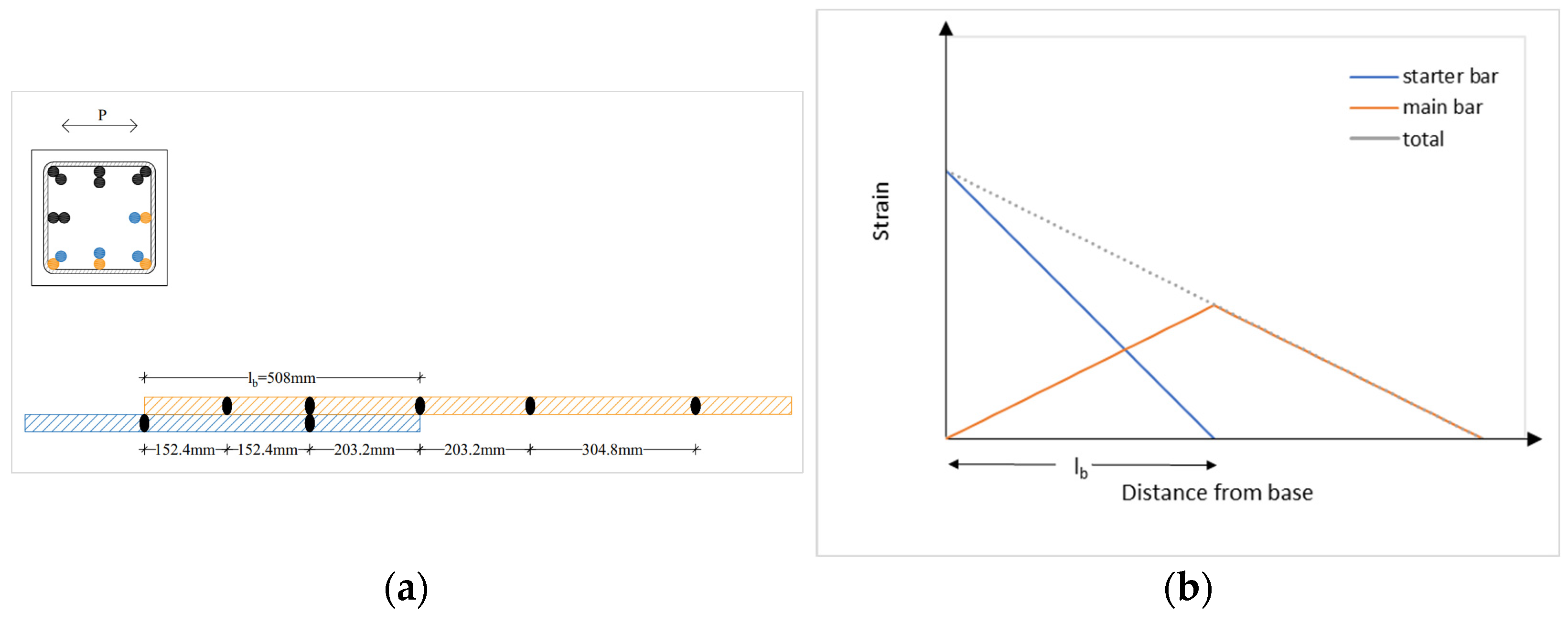
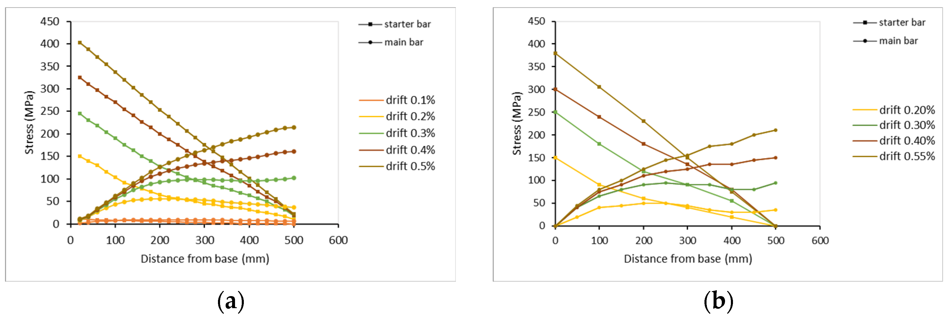
  • In most cases, the developed stress at the base of the column is not fully transferred to the end of the lap splice, as the tensile strain of the bars may be lower far from the bottom section (because of lower moment values). Both bars (starter and main) seem to develop the same stress at about two thirds of the lap splice length away from the bottom section (even in cases of inadequate lap length).
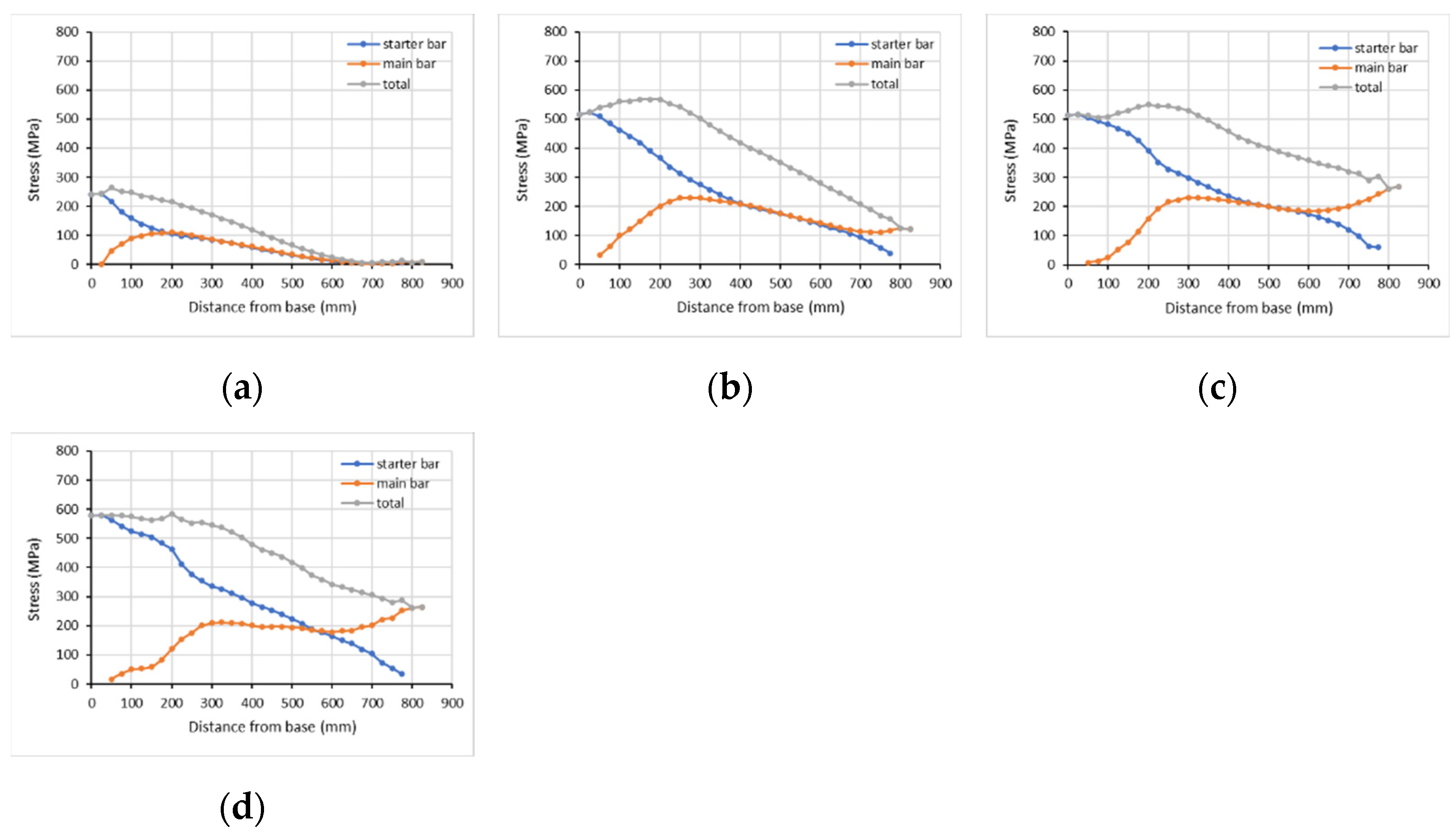
  • In cases where the lap splice length is adequately long (45 dbL), the total bearing tensile stress by both bars at any section is lower at the end of the lap in accordance with the developed moments, similar to the column without laps. For higher column drift, the same pattern is valid, as the bars achieve the hardening behavior of increased bearing stress. Further, if we consider the sum of the developed stress for the lapped bars at any point, the plastic hinge length is extended from 300 mm for R-0L0 without lap, to 400 mm for R-0L4, and to more than double (620 mm) for FRP jacketing at the lap region in R-P2L4.
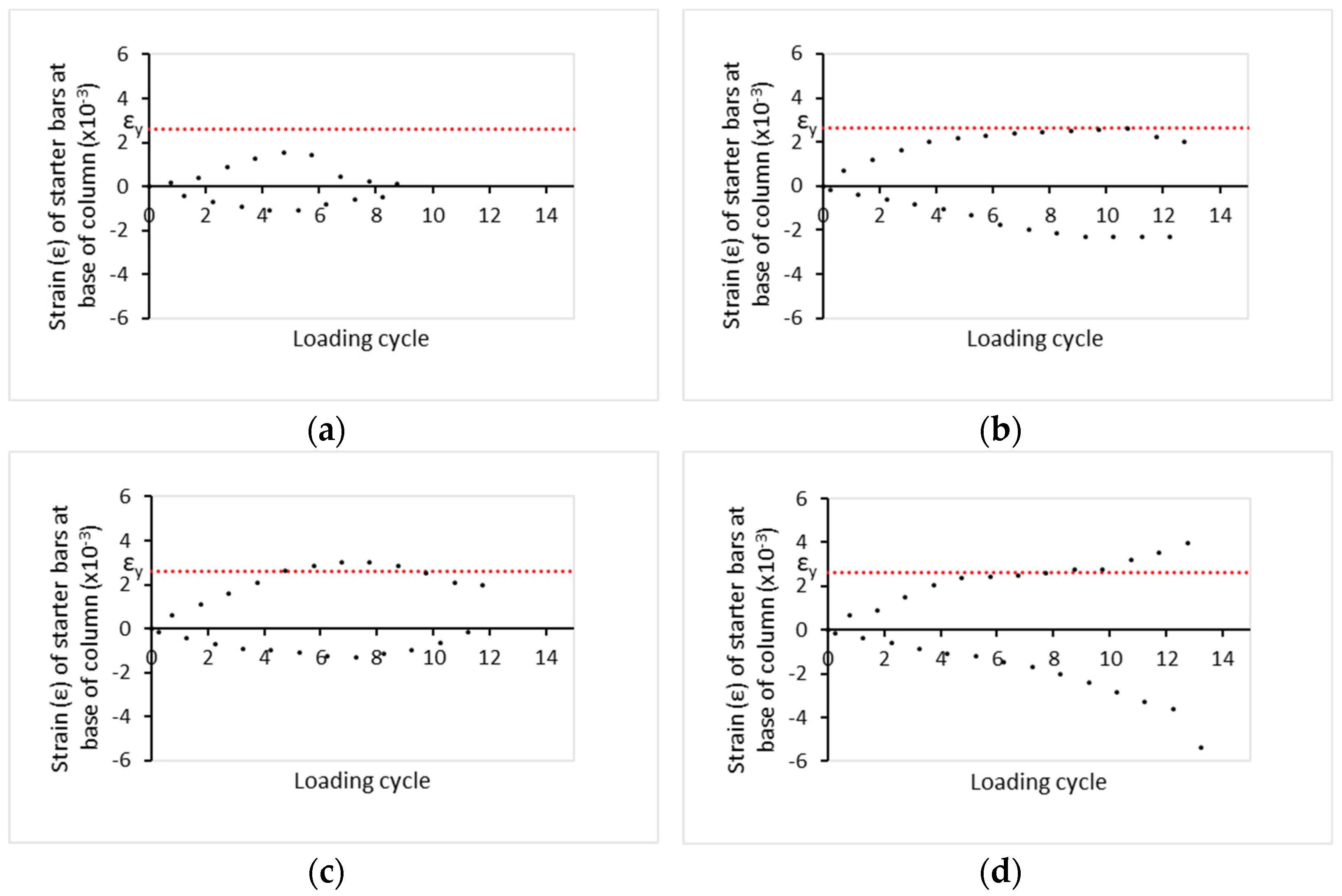
  • In cases the lap splice is 30 dbL the bars develop their yielding, but clearly a slip occurs at ultimate drift. When a column is confined with two layers of FRP, it initially suffers a temporary controlled slip of the bars, starting before the displacement at yielding of the columns R-0L0 or R-P2L0. After delayed bar yielding, the detrimental slip occurs at a far higher ultimate drift. The plastic hinge length is lower than in R-0L4 but higher than in R-0L0 (325 mm). Again, the plastic hinge length extends to around 450 mm or 540 mm for two or five layers of FRP jacketing, based on which is higher for higher lap length or FRP jacketing.
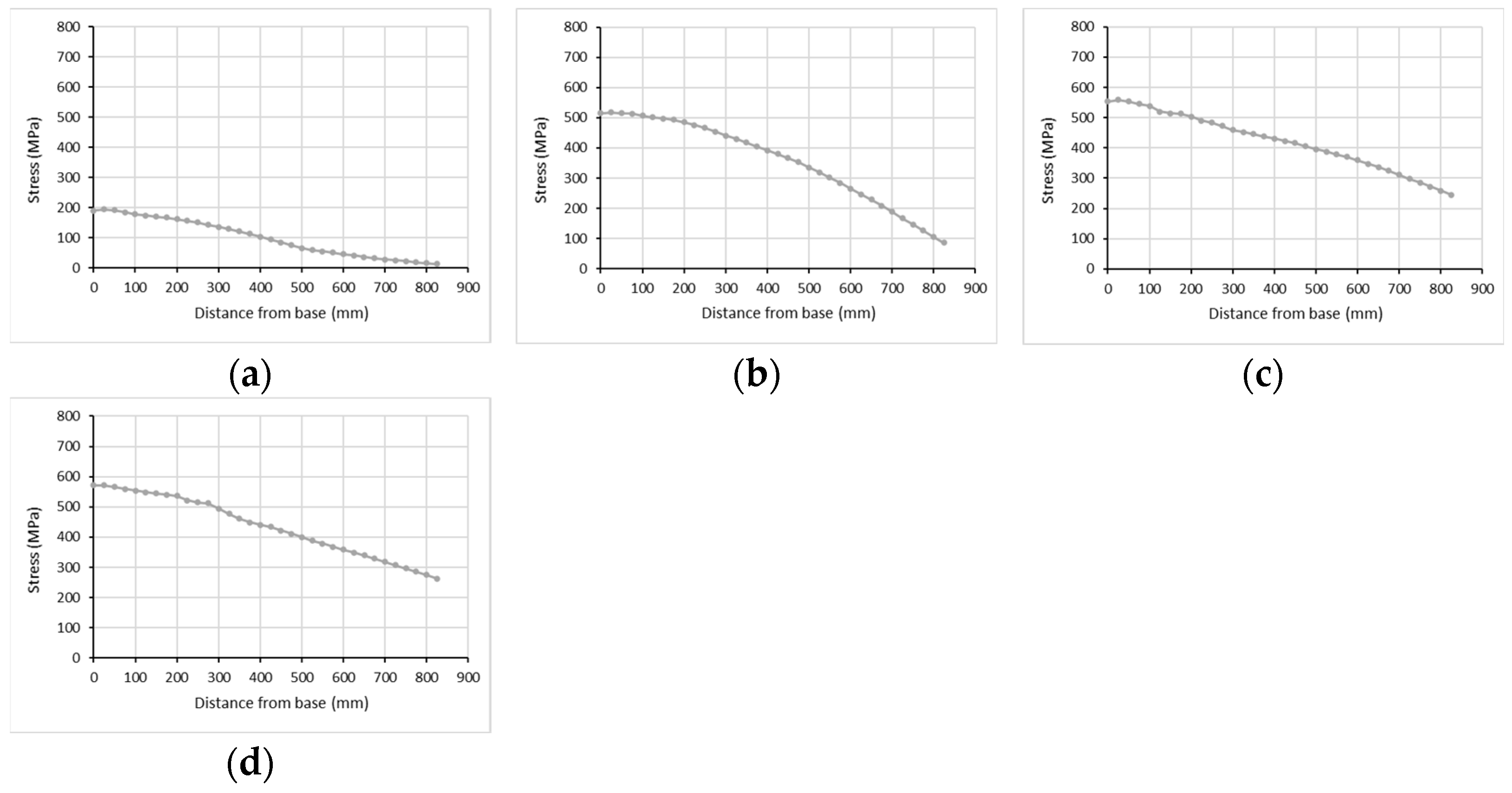
  • In cases where the lap splice length is inadequate (lap length of 15 dbL), the total tensile stress of both bars at any section remains rather constant all along the lap-splice and lower than the yield stress of the bars. This pattern is not affected by external FRP confinement. The total stress of the main bar one may be higher than the starter’s for different horizontal drifts of the column. No plastic hinge length may be defined in these cases, as no bar yielding occurs (despite pseudo-yielding).
  • Increased tensile bar stresses occur at the steel stirrups levels for different columns, as they tend to resist the opening of the potential crack along the spliced bars that leads to their relative slip. The CFRP retrofit seems to improve the axial force transfer mechanism and to result in a better bar stress distribution. The sum of the tensile stress received by both lapped bars increases for more layers of FRP.
  • The height of the provided FRP confinement seems to affect the transfer mechanism of stress along the lap splice. If the FRP does not cover all lap splice regions, then a sudden bar stress decrease at the end of the FRP jacketing occurs.
  • For the first time, cases of smooth bar slip together with delayed bar yielding or without bar yielding are identified that may be recorded through a “ductile” P-d seismic response. Such pseudo-ductile response cases are revisited through suitably revised redesign criteria for adequate FRP jacketing that identify if the lapped bar will yield.
  • The authors propose that composite jacketing that leads to pseudo-ductile P-d behavior while the lapped bar does not yield due to slip (temporary or not) should be considered as inadequate in redesign, and additional FRP layers should be provided as per the framework presented in Section 4.2.2.
  • The high potential of advanced dynamic 3D FEA should be further utilized to extend investigations in several challenging real cases of deficient existing columns with different cross-section geometry, multiple side steel bars inside the lap region, and different detailing of existing steel stirrups or of composite jacketing to assist successful redesign.

Author Contributions

Conceptualization, T.R.; methodology, T.R. and E.A.; formal analysis, T.R. and E.A.; investigation, T.R. and E.A.; writing-review and editing, T.R. and E.A.; visualization, T.R. and E.A.; supervision, T.R.; project administration, T.R. All authors have read and agreed to the published version of the manuscript.

Funding

This research received no external funding.

Data Availability Statement

Not applicable.

Conflicts of Interest

The authors declare no conflict of interest.

References

  1. Rousakis, T.; Ilki, A.; Kwiecien, A.; Viskovic, A.; Gams, M.; Triller, P.; Ghiassi, B.; Benedetti, A.; Rakicevic, Z.; Colla, C.; et al. Deformable Polyurethane Joints and Fibre Grids for Resilient Seismic Performance of Reinforced Concrete Frames with Orthoblock Brick Infills. Polymers 2020, 12, 2869. [Google Scholar] [CrossRef] [PubMed]
  2. Rousakis, T.C.; Panagiotakis, G.D.; Archontaki, E.E.; Kostopoulos, A.K. Prismatic RC columns externally confined with FRP sheets and pre-tensioned basalt fiber ropes under cyclic axial load. Compos. Part B Eng. 2019, 163, 96–106. [Google Scholar] [CrossRef]
  3. Pohoryles, D.A.; Bournas, D.A. Seismic retrofit of infilled RC frames with textile reinforced mortars: State-of-the-art review and analytical modelling. Compos. Part B Eng. 2020, 183, 107702. [Google Scholar] [CrossRef]
  4. Zeng, J.J.; Ye, Y.Y.; Guo, Y.C.; Lv, J.F.; Ouyang, Y.; Jiang, C. PET FRP-concrete-high strength steel hybrid solid columns with strain-hardening and ductile performance: Cyclic axial compressive behavior. Compos. Part B Eng. 2020, 190, 107903. [Google Scholar] [CrossRef]
  5. Park, S.H.; Dinh, N.H.; Um, J.W.; Choi, K.K. Experimental study on the seismic performance of RC columns retrofitted by lap-spliced textile-reinforced mortar jackets after high-temperature exposure. Compos. Struct. 2021, 256, 113108. [Google Scholar] [CrossRef]
  6. Sakthimurugan, K.; Baskar, K. Experimental investigation on rcc external beam-column joints retrofitted with basalt textile fabric under static loading. Compos. Struct. 2021, 268, 114001. [Google Scholar] [CrossRef]
  7. Karayannis, C.G.; Golias, E. Full scale tests of RC joints with minor to moderate seismic damage repaired using C-FRP sheets. Earthq. Struct. 2018, 15, 617–627. [Google Scholar]
  8. Parvin, A.; Jamwal, A.S. Performance of externally FRP reinforced columns for changes in angle and thickness of the wrap and concrete strength. Compos. Struct. 2006, 73, 451–457. [Google Scholar] [CrossRef]
  9. Rousakis, T.C.; Karabinis, A.I. Adequately FRP confined reinforced concrete columns under axial compressive monotonic or cyclic loading. Mater. Struct. 2012, 45, 957–975. [Google Scholar] [CrossRef]
  10. Wang, Z.; Wang, D.; Smith, S.T.; Lu, D. CFRP-confined square RC columns. I: Experimental investigation. J. Compos. Constr. 2012, 16, 150. [Google Scholar] [CrossRef]
  11. Rousakis, T.C. Hybrid confinement of concrete by fiber-reinforced polymer sheets and fiber ropes under cyclic axial compressive loading. J. Compos. Constr. 2013, 17, 732–743. [Google Scholar] [CrossRef]
  12. Triantafyllou, G.G.; Rousakis, T.C.; Karabinis, A.I. Axially loaded reinforced concrete columns with a square section partially confined by light GFRP straps. J. Compos. Constr. 2015, 19, 04014035. [Google Scholar] [CrossRef]
  13. Rousakis, T.C. Reusable and recyclable nonbonded composite tapes and ropes for concrete columns confinement. Compos. Part B Eng. 2016, 100, 15–22. [Google Scholar] [CrossRef]
  14. Fanaradelli, T.; Rousakis, T.; Karabinis, A. Reinforced concrete columns of square and rectangular section, confined with FRP–Prediction of stress and strain at failure. Compos. Part B Eng. 2019, 174, 107046. [Google Scholar] [CrossRef]
  15. Ombres, L.; Mazzuca, P.; Verre, S. Effects of Thermal Conditioning at High Temperatures on the Response of Concrete Elements Confined with a PBO-FRCM Composite System. J. Mater. Civil Eng. 2022, 34, 04021413. [Google Scholar] [CrossRef]
  16. Ma, R.; Xiao, Y.; Li, K. Full-scale testing of a parking structure column retrofitted with carbon fiber reinforced composites. Constr. Build. Mater. 2000, 14, 63–71. [Google Scholar] [CrossRef]
  17. Bousias, S.N.; Spathis, A.L.; Fardis, M.N. Concrete or FRP jacketing of columns with lap splices for seismic rehabilitation. J. Adv. Concr. Technol. 2006, 4, 431–444. [Google Scholar] [CrossRef] [Green Version]
  18. Bournas, D.; Lontou, P.; Papanicolaou, C.; Triantafillou, T. Textile-reinforced mortar vs fiber-reinforced polymer confinement in reinforced concrete columns. ACI Struct. J. 2007, 104, 740–748. [Google Scholar]
  19. Bournas, D.A.; Triantafillou, T.C. Bond strength of lap-spliced bars in concrete confined with composite jackets. J. Comput. Constr. 2011, 15, 157–167. [Google Scholar] [CrossRef]
  20. Bournas, D.A.; Triantafillou, T.C.; Zygouris, K.; Stavropoulos, F. Textile-reinforced mortar versus FRP jacketing in seismic retrofitting of RC columns with continuous or lap-spliced deformed bars. J. Compos. Constr. 2009, 13, 360–371. [Google Scholar] [CrossRef]
  21. Yalcin, C.; Kaya, O.; Sinangil, M. Seismic retrofitting of R/C columns having plain rebars using CFRP sheets for improved strength and ductility. Constr. Build. Mater. 2008, 22, 295–307. [Google Scholar] [CrossRef]
  22. Realfonzo, R.; Napoli, A. Cyclic behavior of RC columns strengthened by FRP and steel devices. J. Struct. Eng. 2009, 135, 1164–1176. [Google Scholar] [CrossRef]
  23. Realfonzo, R.; Napoli, A. Results from cyclic tests on high aspect ratio RC columns strengthened with FRP systems. Constr. Build. Mater. 2012, 37, 606–620. [Google Scholar] [CrossRef]
  24. El Gawady, M.; Endeshaw, M.; McLean, D.; Sack, R. Retrofitting of rectangular columns with deficient lap splices. ASCE. J. Compos. Constr. 2010, 14, 22–35. [Google Scholar] [CrossRef]
  25. Harajli, M.; Rteil, A. Effect of confinement using fiber-reinforced polymer or fiber reinforced concrete on seismic performance of gravity load-designed columns. ACI Struct. J. 2004, 101, 47–56. [Google Scholar]
  26. Harajli, M.H. Bond strengthening of lap spliced reinforcement using external FRP jackets: An effective technique for seismic retrofit of rectangular or circular RC columns. Constr. Build. Mater. 2009, 23, 1265–1278. [Google Scholar] [CrossRef]
  27. Harajli, M. Seismic behavior of RC columns with bond-critical regions: Criteria for bond strengthening using external FRP jackets. ASCE J. Compos. Constr. 2008, 12, 69–79. [Google Scholar] [CrossRef]
  28. Harajli, M.H.; Dagher, F. Seismic strengthening of bond-critical regions in rectangular reinforced concrete columns using fiber-reinforced polymer wraps. ACI Struct. J. 2008, 105, 68. [Google Scholar]
  29. Harajli, M.H.; Dagher, F.K.; ElSouri, A.M. Cyclic response of rectangular RC columns with bond-damaged zones repaired using steel or CFRP confinement. Spec. Publ. 2010, 272, 225–250. [Google Scholar]
  30. Haroun, M.A.; Mossalam, A.S.; Feng, Q.; Elsanadedy, H.M. Experimental investigation of seismic repair and retrofit of bridge columns by composite jackets. FRP Compos. Civ. Eng. 2001, I, 1243–1268. [Google Scholar] [CrossRef]
  31. Haroun, M.A.; Elsanadedy, H.M. Behavior of cyclically loaded squat reinforced concrete bridge columns upgraded with advanced composite-material jackets. J. Bridge Eng. 2005, 10, 741–748. [Google Scholar] [CrossRef]
  32. Haroun, M.A.; Elsanadedy, H.M. Fiber-reinforced plastic jackets for ductility enhancement of reinforced concrete bridge columns with poor lap-splice detailing. J. Bridge Eng. 2005, 10, 749–757. [Google Scholar] [CrossRef]
  33. Chang, K.; Liu, K.; Chang, S. Seismic retrofit study of RC rectangular bridge columns lap-spliced at the plastic hinge zone. FRP Compos. Civ. Eng. 2001, I, 869–875. [Google Scholar]
  34. Eshghi, S.; Zanjanizadeh, V. Retrofit of slender square reinforced concrete columns with glass fiber-reinforced polymer for seismic resistance. Iran J. Sci. Technol. Trans. B Eng. 2008, 32, 437–450. [Google Scholar]
  35. Ghosh, K.K.; Sheikh, S.A. Seismic upgrade with carbon fiber reinforced polymer of columns containing lap-spliced reinforcing bars. ACI Struct. J. 2007, 104, 227–236. [Google Scholar]
  36. Sheikh, S.A.; Li, Y. Design of FRP confinement for square concrete columns. Eng. Struct. 2007, 29, 1074–1083. [Google Scholar] [CrossRef]
  37. Saadatmanesh, H.; Ehsani, M.R.; Jin, L. Repair of earthquake-damaged RC columns with FRP wraps. ACI Struct. J. 1997, 94, 206–214. [Google Scholar]
  38. Saadatmanesh, H.; Ehsani, M.R.; Jin, L. Seismic retrofitting of rectangular bridge columns with composite straps. Earthq. Spectra 1997, 13, 281–304. [Google Scholar] [CrossRef]
  39. Kalogeropoulos, G.; Tsonos, A.D. Cyclic Performance of RC Columns with Inadequate Lap Splices Strengthened with CFRP Jackets. Fibers 2020, 8, 39. [Google Scholar] [CrossRef]
  40. N 1998-1:2004; Eurocode 8: Design of Structures for Earthquake Resistance—Part 3: Assessment and Retrofitting of Buildings. European Committee for Standardization: Brussels, Belgium, 2005.
  41. Greek Retrofit Code (KANEPE), 2nd ed.; 2017. Available online: https://oasp.gr/node/92 (accessed on 25 May 2021).
  42. Anagnostou, E.; Rousakis, T.C.; Karabinis, A.I. Seismic retrofitting of damaged RC columns with lap-spliced bars using FRP sheets. Compos. Part B Eng. 2019, 166, 598–612. [Google Scholar] [CrossRef]
  43. Anagnostou, E.; Rousakis, T. Seismic retrofitting of damaged RC columns with composites and other techniques. In Proceedings of the 25th Annual International Conference on Composites or Nano Engineering (ICCE-25), Rome, Italy, 16–22 July 2017. [Google Scholar]
  44. Seyhan, E.C.; Goksu, C.; Uzunhasanoglu, A.; Ilki, A. Seismic behavior of substandard RC columns retrofitted with embedded aramid fiber reinforced polymer (AFRP) reinforcement. Polymers 2015, 7, 2535–2557. [Google Scholar] [CrossRef] [Green Version]
  45. Farrokh Ghatte, H.; Comert, M.; Demir, C.; Akbaba, M.; Ilki, A. Seismic retrofit of full-scale substandard extended rectangular RC columns through CFRP jacketing: Test results and design recommendations. J. Compos. Constr. 2019, 23, 04018071. [Google Scholar] [CrossRef]
  46. Dai, J.G.; Lam, L.; Ueda, T. Seismic retrofit of square RC columns with polyethylene terephthalate (PET) fibre reinforced polymer composites. Constr. Build. Mater. 2012, 27, 206–217. [Google Scholar] [CrossRef]
  47. Biskinis, D.; Fardis, M.N. Flexure-controlled ultimate deformations of members with continuous or lap-spliced bars. Struct. Concr. 2010, 11, 93–108. [Google Scholar] [CrossRef]
  48. Grammatikou, S.; Biskinis, D.; Fardis, M.N. Effect of load cycling, FRP jackets, and lap-splicing of longitudinal bars on the effective stiffness and ultimate deformation of flexure-controlled RC members. J. Struct. Eng. 2018, 144, 04018056. [Google Scholar] [CrossRef]
  49. Jiang, C.; Wu, Y.F.; Wu, G. Plastic hinge length of FRP-confined square RC columns. J. Compos. Constr. 2014, 18, 04014003. [Google Scholar] [CrossRef]
  50. Yuan, F.; Wu, Y.F. Effect of load cycling on plastic hinge length in RC columns. Eng. Struct. 2017, 147, 90–102. [Google Scholar] [CrossRef]
  51. Yuan, F.; Wu, Y.F.; Li, C.Q. Modelling plastic hinge of FRP-confined RC columns. Eng. Struct. 2017, 131, 651–668. [Google Scholar] [CrossRef]
  52. Triantafyllou, G.G.; Rousakis, T.C.; Karabinis, A.I. Corroded RC beams patch repaired and strengthened in flexure with fiber-reinforced polymer laminates. Compos. Part B Eng. 2017, 112, 125–136. [Google Scholar] [CrossRef]
  53. Rousakis, T.C.; Manolitsi, G.; Karabinis, A.I. FRP strengthening of RC columns: Parametric finite element analyses of bar quality effect. In Proceedings of the 1st Asia-Pacific Conference on FRP in Structures (APFIS 2007), Hong Kong, China, 12–14 December 2007. [Google Scholar]
  54. Karabinis, A.I.; Rousakis, T.C.; Manolitsi, G.E. 3D finite-element analysis of substandard RC columns strengthened by fiber-reinforced polymer sheets. J. Compos. Constr. 2008, 12, 531–540. [Google Scholar] [CrossRef]
  55. Rousakis, T.C.; Karabinis, A.I.; Kiousis, P.D.; Tepfers, R. Analytical modelling of plastic behaviour of uniformly FRP confined concrete members. Compos. Part B Eng. 2008, 39, 1104–1113. [Google Scholar] [CrossRef]
  56. Charalambidi, B.; Rousakis, T.; Karabinis, A. Finite Element Modeling of Reinforced Concrete Columns Seismically Strengthened through Partial FRP Jacketing. In Proceedings of the 15th World Conference on Earthquake Engineering, Lisbon, Portugal, 24–28 September 2012. [Google Scholar]
  57. Chalioris, C.E.; Kytinou, V.K.; Voutetaki, M.E.; Karayannis, C.G. Flexural damage diagnosis in reinforced concrete beams using a wireless admittance monitoring system—Tests and finite element analysis. Sensors 2021, 21, 679. [Google Scholar] [CrossRef] [PubMed]
  58. Yuan, F.; Pan, J.; Wu, Y. Numerical study on flexural behaviors of steel reinforced engineered cementitious composite (ECC) and ECC/concrete composite beams. Sci. China Technol. Sci. 2014, 57, 637–645. [Google Scholar] [CrossRef]
  59. Nisticò, N.; Ožbolt, J.; Polimanti, G. Modeling of reinforced concrete beams strengthened in shear with CFRP: Microplane-based approach. Compos. Part B Eng. 2016, 90, 351–364. [Google Scholar] [CrossRef]
  60. Hany, N.F.; Hantouche, E.G.; Harajli, M.H. Finite element modeling of FRP-confined concrete using modified concrete damaged plasticity. Eng. Struct. 2016, 125, 1–14. [Google Scholar] [CrossRef]
  61. Ozbakkaloglu, T.; Gholampour, A.; Lim, J.C. Damage-plasticity model for FRP-confined normal-strength and high-strength concrete. J. Compos. Constr. 2016, 20, 04016053. [Google Scholar] [CrossRef]
  62. Yu, T.T.; Teng, J.G.; Wong, Y.L.; Dong, S.L. Finite element modeling of confined concrete-I: Drucker–Prager type plasticity model. Eng. Struct. 2010, 32, 665–679. [Google Scholar] [CrossRef]
  63. Yu, T.; Teng, J.G.; Wong, Y.L.; Dong, S.L. Finite element modeling of confined concrete-II: Plastic-damage model. Eng. Struct. 2010, 32, 680–691. [Google Scholar] [CrossRef]
  64. Rousakis, T.; Anagnostou, E.; Fanaradelli, T. Advanced Composite Retrofit of RC Columns and Frames with Prior Damages-Pseudodynamic Finite Element Analyses and Design Approaches. Fibers 2021, 9, 56. [Google Scholar] [CrossRef]
  65. Rousakis, T.; Anagnostou, E.; Fanaradelli, T. Pseudo-dynamic analyses of infilled reinforced concrete framed structures with prior damages after advanced retrofit. In Proceedings of the 8th International Conference on Computational Methods in Structural Dynamics and Earthquake Engineering (COMPDYN 2021), Athens, Greece, 27–30 June 2021. [Google Scholar]
  66. Rousakis, T.; Vanian, V.; Fanaradelli, T.; Anagnostou, E. 3D FEA of infilled RC framed structures protected by seismic joints and FRP jackets. Appl. Sci. 2021, 11, 6403. [Google Scholar] [CrossRef]
  67. Anagnostou, E.; Rousakis, T.; Georgiadis, N. Finite element analysis of deficient RC columns with square and rectangular section under pseudoseismic load and comparison with retrofit code predictions. In Proceedings of the ICCE-26 Conference, Paris, France, 15–21 July 2018. [Google Scholar]
  68. Rousakis, T.C.; Saridaki, M.E.; Mavrothalassitou, S.A.; Hui, D. Utilization of hybrid approach towards advanced database of concrete beams strengthened in shear with FRPs. Compos. Part B Eng. 2016, 85, 315–335. [Google Scholar] [CrossRef]
  69. Fanaradelli, T.D.; Rousakis, T.C. 3D Finite Element Pseudodynamic Analysis of Deficient RC Rectangular Columns Confined with Fiber Reinforced Polymers under Axial Compression. Polymers 2020, 12, 2546. [Google Scholar] [CrossRef] [PubMed]
  70. Biskinis, D.; Fardis, M.N. Models for FRP-wrapped rectangular RC columns with continuous or lap-spliced bars under cyclic lateral loading. Eng. Struct. 2013, 57, 199–212. [Google Scholar] [CrossRef]
  71. Bousias, S.N.; Triantafillou, T.C.; Fardis, M.N.; Spathis, L.; O’Regan, B.A. Fiber-reinforced polymer retrofitting of rectangular reinforced concrete columns with or without corrosion. Struct. J. 2004, 101, 512–520. [Google Scholar]
  72. Eshghi, S.; Zanjanizadeh, V. Repair of earthquake-damaged square R/C columns with glass fiber-reinforced polymer. Int. J. Civ. Eng. 2007, 5, 210–223. [Google Scholar]
  73. Vrettos, I.; Kefala, E.; Triantafillou, T. Innovative flexural strengthening of reinforced concrete columns using carbon-fiber anchors. ACI Struct. J. 2013, 110, 63–70. [Google Scholar]
  74. Ghobarah, A.; Galal, K. Seismic rehabilitation of short rectangular rc columns. J. Earthq. Eng. 2004, 8, 45–68. [Google Scholar] [CrossRef]
  75. Colomb, F.; Tobbi, H.; Ferrier, E.; Hamelin, P. Seismic retrofit of reinforced concrete short columns by CFRP materials. Compos. Struct. 2008, 82, 475–487. [Google Scholar] [CrossRef]
  76. Ye, L.P.; Zhang, K.; Zhao, S.H.; Feng, P. Experimental study on seismic strengthening of RC columns with wrapped CFRP sheets. J. Constr. Build. Mater. 2003, 17, 499–506. [Google Scholar] [CrossRef]
  77. Ye, L.; Yue, O.; Zhao, S.; Li, Q. Shear strength of reinforced concrete columns strengthened with carbon-fiber-reinforced plastic sheet. ASCE J. Comp. Constr. 2002, 128, 1527–1534. [Google Scholar] [CrossRef]
  78. Kim, J.; Kwon, M.; Jung, W.; Limkatanyu, S. Seismic performance evaluation of RC columns reinforced by GFRP composite sheets with clip connectors. Constr. Build. Mater. 2013, 43, 563–574. [Google Scholar] [CrossRef]
  79. Lee, Y.T.; Kim, S.H.; Hwang, H.S.; Lee, L.H. Evaluation on the shear strengthening effect of RC columns with carbon fiber sheets. In Proceedings of the 13th World Conference on Earthquake Engineering, Vancouver, BC, Canada, 1–6 August 2004. [Google Scholar]
  80. Sadone, R.; Quiertant, M.; Mercier, J.; Ferrier, E. Experimental study on RC columns retrofitted by FRP and subjected to seismic loading. In Proceedings of the 6th International Conference on FRP Composites in Civil Engineering, Rome, Italy, 13–15 June 2012. [Google Scholar]
  81. Promis, G.; Ferrier, E. Performance indices to assess the efficiency of external FRP retrofitting of reinforced concrete short columns for seismic strengthening. Constr. Build. Mater. 2012, 26, 32–40. [Google Scholar] [CrossRef]
  82. Sause, R.; Harries, K.A.; Waikup, S.L.; Pessiki, S.; Ricles, J.M. Flexural behavior of concrete columns retrofitted with carbon fiber-reinforced polymer jackets. ACI Struct. J. 2004, 101, 708–716. [Google Scholar]
  83. Yoshimura, K.; Kikuchi, K.; Kuroki, M.; Wang, J.; Ichinose, K. Seismic strengthening of rectangular R/C columns confined by circular steel- and CF-jackets. In Proceedings of the 13th World Conference on Earthquake Engineering, Vancouver, BC, Canada, 1–6 August 2004. [Google Scholar]
  84. Thermou, G.E.; Pantazopoulou, S.J. Fiber-reinforced polymer retrofitting of predamaged substandard RC prismatic members. J. Compos. Constr. 2009, 13, 535–546. [Google Scholar] [CrossRef]
  85. Kwon, M.; Seo, H.; Kim, J. Seismic performance of RC-column wrapped with velcro. Struct. Eng. Mech. 2016, 58, 379–395. [Google Scholar] [CrossRef]
  86. Anggawidjaja, D.; Ueda, T.; Dai, J.; Nakai, H. Deformation capacity of RC piers wrapped by new fiber-reinforced polymer with large fracture strain. Cement. Concr. Compos. 2006, 28, 914–927. [Google Scholar] [CrossRef]
  87. Juntanalikit, P.; Jirawattanasomkul, T.; Pimanmas, A. Experimental and numerical study of strengthening non-ductile RC columns with and without lap splice by CFRP jacketing. Eng. Struct. 2016, 125, 400–418. [Google Scholar] [CrossRef]
  88. Fahmy, M.; Wu, Z. Exploratory study of seismic response of deficient lap-splice columns retrofitted with near surface–mounted basalt FRP bars. J. Struct. Eng 2016, 142, 04016020. [Google Scholar] [CrossRef]
  89. Oscan, O.; Binici, B.; Canbay, E.; Ozcebe, G. Repair and strengthening of reinforced concrete columns with CFRPs. J. Reinf. Plast. Compos. 2015, 29, 3411–3424. [Google Scholar] [CrossRef]
  90. Ozcan, O.; Binici, B.; Ozcebe, G. Improving seismic performance of deficient reinforced concrete columns using carbon fiber-reinforced polymers. Eng. Struct. 2008, 30, 1632–1646. [Google Scholar] [CrossRef]
  91. Ozcan, O.; Binici, B.; Ozcebe, G. Seismic strengthening of rectangular concrete columns using fiber reinforced polymers. Eng. Struct. 2010, 32, 964–973. [Google Scholar] [CrossRef]
  92. Abdel-Mooty, M.; Issa, M.; Farag, H.; Bitar, M. Seismic upgrading of square and rectangular RC columns using FRP wrapping. High. Perform. Struct. Mater. III 2006, 85, 419–428. [Google Scholar]
  93. He, R.; Sneed, L.; Belarbi, A. Rapid repair of severely damaged RC columns with different damage conditions. An Experimental Study. Intern. J. Conc. Struct. Mater. 2013, 7, 35–50. [Google Scholar] [CrossRef] [Green Version]
  94. ElSouri, A.; Harajli, M. Seismic repair and strengthening of lap splices in RC columns: Carbon fiber–reinforced polymer versus steel confinement. ASCE. J. Compos. Constr. 2011, 15, 721–731. [Google Scholar] [CrossRef]
  95. Goksu, C.; Ilki, A. Seismic Behavior of Reinforced Concrete Columns with Corroded Deformed Reinforcing Bars. ACI Struct. J. 2016, 113, 1053–1064. [Google Scholar] [CrossRef]
  96. Guo, A.; Li, H.; Ba, X.; Guan, X.; Li, H. Experimental investigation on the cyclic performance of reinforced concrete piers with chloride-induced corrosion in marine environment. Eng. Struct. 2015, 105, 1–11. [Google Scholar] [CrossRef]
  97. Yang, S.Y.; Song, X.B.; Jia, H.X.; Chen, X.; Liu, X.L. Experimental research on hysteretic behaviors of corroded reinforced concrete columns with different maximum amounts of corrosion of rebar. Constr. Build. Mater. 2016, 121, 319–327. [Google Scholar] [CrossRef]
  98. Rajput, A.S.; Sharma, U.K. Corroded reinforced concrete columns under simulated seismic loading. Eng. Struct. 2018, 171, 453–463. [Google Scholar] [CrossRef]
  99. Li, J.; Gong, J.; Wang, L. Seismic behavior of corrosion-damaged reinforced concrete columns strengthened using combined carbon fiber-reinforced polymer and steel jacket. Constr. Build. Mater. 2009, 23, 2653–2663. [Google Scholar] [CrossRef]
  100. Li, D.; Wei, R.; Xing, F.; Sui, L.; Zhou, Y.; Wang, W. Influence of Non-uniform corrosion of steel bars on the seismic behavior of reinforced concrete columns. Constr. Build. Mater. 2018, 167, 20–32. [Google Scholar]
  101. Riedel, W.; Kawai, N.; Kondo, K.I. Numerical assessment for impact strength measurements in concrete materials. Intern. J. Impact. Eng. 2009, 36, 283–293. [Google Scholar] [CrossRef] [Green Version]
  102. Bencardino, F.; Nisticò, M.; Verre, S. Experimental investigation and numerical analysis of bond behavior in SRG-strengthened masonry prisms using UHTSS and stainless-steel fibers. Fibers 2020, 8, 8. [Google Scholar] [CrossRef] [Green Version]
  103. Carozzi, F.G.; Colombi, P.; Fava, G.; Poggi, C. A cohesive interface crack model for the matrix–textile debonding in FRCM composites. Compos. Struct. 2016, 143, 230–241. [Google Scholar] [CrossRef]
  104. Hawileh, R.A.; El-Maaddawy, T.A.; Naser, M.Z. Nonlinear finite element modeling of concrete deep beams with openings strengthened with externally-bonded composites. Mater. Design 2012, 42, 378–387. [Google Scholar] [CrossRef]
  105. Anıl, Ö.; Durucan, C.; Kara, M.E.; Başeğmez, Ö. Nonlinear three-dimensional FE analyses of RC beams retrofitted using externally bonded CFRP sheets with or without anchorages. J. Adhes. Sci. Technol. 2017, 31, 770–786. [Google Scholar] [CrossRef]
  106. Kargaran, A.; Kheyroddin, A. Experimental and numerical investigation of seismic retrofitting of RC square short columns using FRP composites. European J. Environ. Civil Eng. 2022, 26, 4619–4642. [Google Scholar] [CrossRef]
  107. Melek, M.; Conte, J.P.; Wallace, J.W. Experimental assessment of columns with short lap splices subjected to cyclic loads. Pacific Earthq. Eng. Res. Cent. 2003; Peer Report 2003/4. [Google Scholar]
  108. Chowdhury, S.R.; Orakcal, K. An analytical model for reinforced concrete columns with lap splices. Eng. Struct. 2012, 43, 180–193. [Google Scholar] [CrossRef]
Figure 1. Parts of FE model (a) concrete, (b) internal (steel) reinforcement, (c) external reinforcement (FRP jacket).
Fibers 10 00107 g001
Figure 2. Boundary conditions and loading of (a) unretrofitted and (b) retrofitted columns.
Fibers 10 00107 g002
Figure 3. Lateral Force-Drift curves for columns (a) R-0L0, (b) R-0L1, (c) R-0L3, (d) R-0L4, (e) R-P2L0, (f) R-P2L1, (g) R-P2L3, (h) R-P2L4 and (i) R-P5L3.
Fibers 10 00107 g003
Figure 4. Comparative F-δ curves of unretrofitted columns.
Fibers 10 00107 g004
Figure 5. Comparative F-δ curves of retrofitted columns.
Fibers 10 00107 g005
Figure 6. Peak pull and push steel strain of starter bars at the base of column (a) L20d_C, (b) L20d_R2, (c) L40d_C and (d) L40d_R2 at each loading cycle (based on results by [19]).
Fibers 10 00107 g006
Figure 7. Definition of (a) yield Fy and (b) pseudo-yield Fpy.
Fibers 10 00107 g007
Figure 8. (a) Strain gauges layout. (b) Expected strain distribution along lap-spliced bars (based on [107]).
Fibers 10 00107 g008
Figure 9. Strain distribution of (a) corner and (b) middle bars of column S20MI (based on [107]).
Fibers 10 00107 g009
Figure 10. Predicted steel stress distribution on starter and main bar, for (a) monotonic analysis, and (b) cyclic analysis (based on results by [108]).
Fibers 10 00107 g010
Figure 11. Developed stress along starter longitudinal bars in tension at a displacement of (a) 3.39 mm, (b) 9.74 mm (δy), (c) 23.88 mm (δPmax) and (d) 36.86 mm (δu), for column R-0L0.
Fibers 10 00107 g011
Figure 12. Developed stress along lap splice length at a displacement of (a) 3.15 mm, (b) 8.19 mm (δy), (c) 22.34 mm (δPmax), and (d) 31.36 mm (δu), for column R-0L4.
Fibers 10 00107 g012
Figure 13. Developed stress along lap splice length at a displacement of (a) 4.70 mm, (b) 8.91 mm, (c) 12.02 mm (δy), (d) 26.50 mm (δPmax), and (e) 96.27 mm (δu), for column R-P2L4.
Fibers 10 00107 g013
Figure 14. Developed stress along lap splice length at a displacement of (a) 3.16 mm, (b) 8.22 mm (δy), (c) 16.64 mm (δPmax), and (d) 27.20 mm (δu), for column R-0L3.
Fibers 10 00107 g014
Figure 15. Developed stress along lap splice length at a displacement of (a) 2.07 mm, (b) 4.20 mm, (c) 6.58 mm (δpy), (d) 36.21 mm (δP€), (e) 49.30 mm (δy), and (f) 69.11 mm (δu), for column R-P2L3.
Fibers 10 00107 g015
Figure 16. Developed stress along lap splice length at a displacement of (a) 3.44 mm, (b) 7.23 mm, (c) 10.14 mm (δpy), (d) 37.83 mm (Pmax), (e) 51.20 mm (δy), and (f) 97.17 mm (δu), for column R-P5L3.
Fibers 10 00107 g016aFibers 10 00107 g016b
Figure 17. Developed stress along lap splice length at a displacement of (a) 3.15 mm, (b) 8.57 mm (δpy), (c) 16.95 mm (δPmax), and (d) 28.50 mm (δu), for column R-0L1.
Fibers 10 00107 g017
Figure 18. Developed stress along lap splice length at a displacement of (a) 2.24 mm, (b) 4.49 mm, (c) 7.29 mm (δpy), (d) 26.28 mm (δPmax), and (e) 49.36 mm (δu), for column R-P2L1.
Fibers 10 00107 g018
Table 1. Features of selected columns for pseudo-dynamic 3D FE analyses.
Columnfc
(MPa)
GeometryFRPLongitudinal BarsStirrupsv
bw
(m)
h
(m)
Ls
(m)
Type of
FRP
Height of FRP
(mm)
tj
(mm)
Ej
(GPa)
εjur
(mm)
dbL
(mm)
Lap-splice Length
(dbL)
fyL
(MPa)
fuL
(MPa)
dw
(mm)
fyw
(MPa)
s
(m)
fuw
(MPa)
R-0L031.00.2500.5001.60----- 18-51465984250.25960.26
R-0L127.40.2500.5001.60----- 181551465984250.25960.23
R-0L327.40.2500.5001.60----- 183051465984250.25960.28
R-0L427.40.2500.5001.60----- 184551465984250.25960.28
R-P2L032.90.2500.5001.60CFRP6000.262300.0153018-51465984250.25960.23
R-P2L126.90.2500.5001.60CFRP6000.262300.01530181551465984250.25960.30
R-P2L326.90.2500.5001.60CFRP6000.262300.01530183051465984250.25960.28
R-P2L426.90.2500.5001.60CFRP6000.262300.01530184551465984250.25960.28
R-P5L327.00.2500.5001.60CFRP6000.652300.01530183051465984250.25960.29
fc: concrete compressive strength, bw: width of cross-section, h: depth of cross-section, Ls: shear span length, tj: total thickness of FRP jacket, Ej: elastic modulus of CFRP, εju: strain at failure of CFRP, r: bend radius of FRP at the corners of the member, dbL: diameter of longitudinal steel bar, fyL: yield stress of longitudinal steel bar, fuL: ultimate stress of longitudinal steel bar, dw: diameter of transverse steel bar, fyw: yield stress of transverse reinforcement, s: stirrup spacing, fuw: ultimate stress of transverse reinforcement, v: normalized axial force.
Table 2. Basic concrete material parameters.
PropertyValue
Density (kg·m−3)2314
Tensile Strength ft/fc0.1
Shear Strength fs/fc0.18
Intact Failure Surface Constant A1.6
Intact Failure Surface Exponent n0.61
Tension/Compression Meridian Ratio Q2.00.6805
Brittle to Ductile Transition BQ0.0105
Hardening Slope2
Elastic Strength/ft0.7
Elastic Strength/fc0.53
Table 3. Basic steel material parameters.
PropertyValue
Density (kg·m−3)7850
Isotropic elasticityYoung’s Modulus (MPa)2 × 10⁵
Poisson’s Ratio0.3
Bulk Modulus (Pa)1.6667 × 10¹¹
Shear Modulus (Pa)7.6923 × 10¹⁰
Plastic StrainStress
Multilinear isotropic hardening
(Steel stirrups)
0425
0.05550
0.1580
0.195596
Multilinear isotropic hardening
(Longitudinal bars)
0514
0.05630
0.1650
0.17659
Table 4. Basic CFRP jacket parameters.
PropertyValue
Density (kg·m−3)1.451 × 10⁻⁹
Young’s Modulus X direction (MPa)59,160
Young’s Modulus Y direction (MPa)59,160
Table 5. Comparative experimental and numerical results of columns R-0L0, R-0L1, R-0L3, R-0L4, R-P2L0, R-P2L1, R-P2L3, R-P2L4, and R-P5L3.
ColumnResultsPmax
(kN)
AE
(%)
Pu,exp
(kN)
δPu
(mm)
δPu AE
(%)
δu,exp
(mm)
Pδu
(kN)
Pδu AE
(%)
R-0L0Experimental196.500.79157.2040.006.9340.00157.202.06
numerical194.95157.2037.2340.00153.96
R-0L1Experimental148.005.63123.4030.4010.7930.40123.4012.77
numerical139.67123.4027.1230.40107.64
R-0L3Experimental173.757.67139.0030.401.7830.40139.001.64
numerical187.07139.0030.9430.40141.28
R-0L4Experimental205.006.32164.0039.0022.9239.00164.0019.62
numerical192.05164.0030.0639.00131.82
R-P2L0Experimental217.000.33173.6067.2014.0267.20173.605.67
numerical217.73173.6076.6267.20183.44
R-P2L1Experimental171.503.13137.2052.2015.3152.20137.2011.84
numerical176.86137.2060.1952.20153.45
R-P2L3Experimental211.501.13169.2070.105.3470.10169.207.29
numerical209.11169.2066.3670.10156.86
R-P2L4Experimental208.501.24166.8087.3010.2787.30166.804.46
numerical211.08166.8096.2787.30174.24
R-P5L3Experimental225.251.04180.0089.308.8189.30180.004.73
numerical222.90180.0097.1789.30188.52
Table 6. Comparison of analytical and experimental values of chord rotation at failure.
(1)(2)(3)(4)(5)(6)(7)(8)(9)(10)
ColumnLap Length
(dbL)
Layers CFRPθu,expθu,pred
(KANEPE)
AE
(%)
θu,pred
(EC8.3)
AE
(%)
θu,prop
(Proposed-
Including Equation c)
AE
(%)
R-P2L0020.0440.04224.10.04194.90.04194.8
R-P2L11520.0340.012164.50.016750.90.03523.5
R-P2L33020.0470.023151.00.022751.70.04425.9
R-P2L44520.0560.030345.90.029846.80.046716.5
R-P5L33050.0560.025654.30.025255.00.063212.8
AAE(%) 44.0 41.9 8.7
AR 0.56 0.58 0.98
Publisher’s Note: MDPI stays neutral with regard to jurisdictional claims in published maps and institutional affiliations.

