
Evaluation of the Tensile Characteristics and Bond Behaviour of Steel Fibre-Reinforced Concrete: An Overview


Abstract
:1. Introduction
2. Bond Behaviour of Steel Fibre Reinforced Concrete
3. Types of Bond
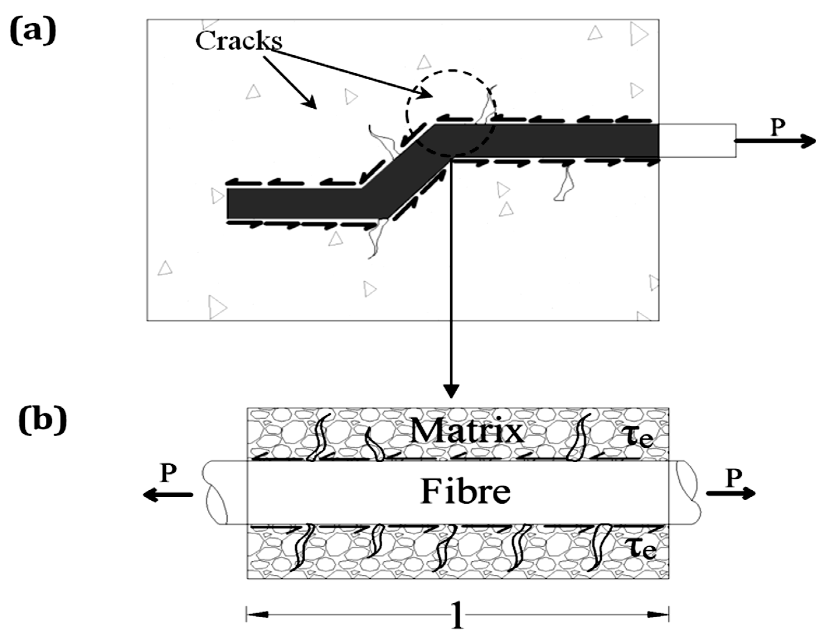
3.1. Shear Bond
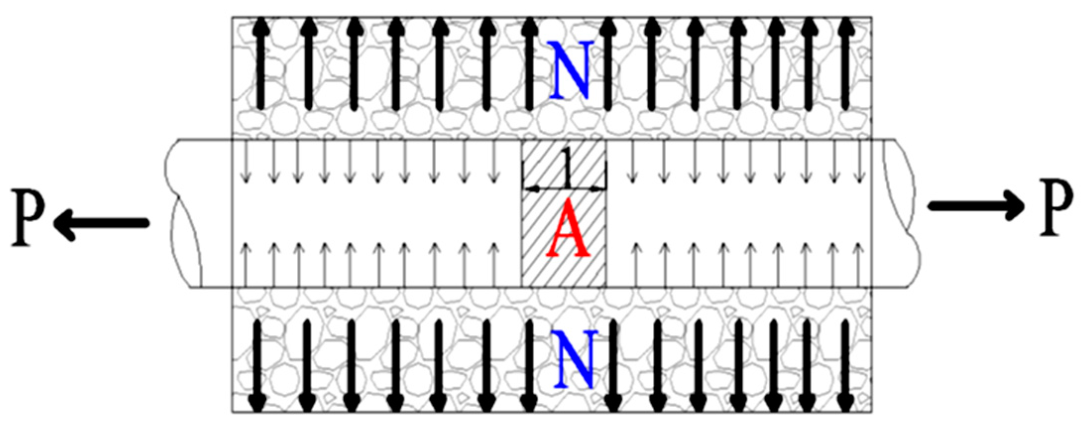
3.2. Tensile Bond
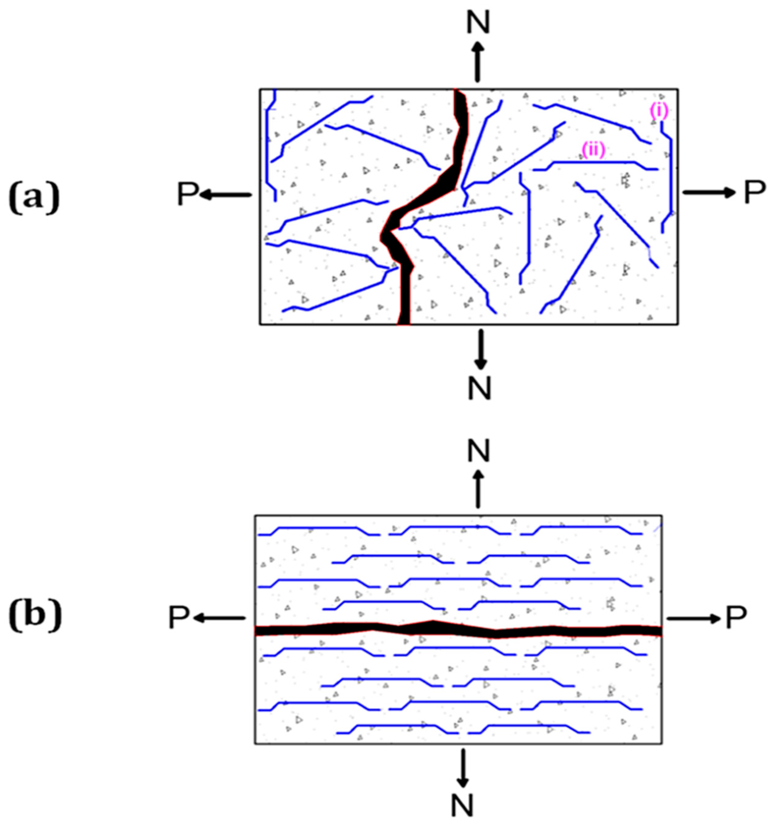
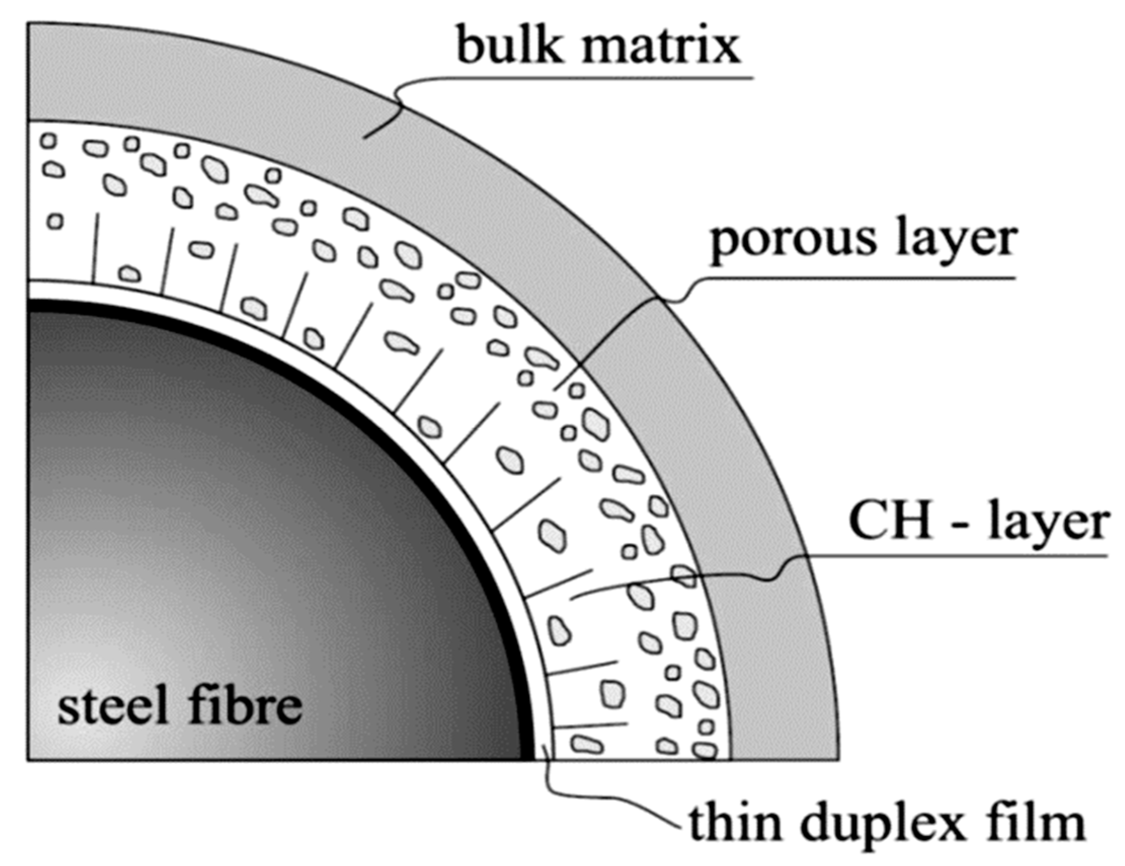
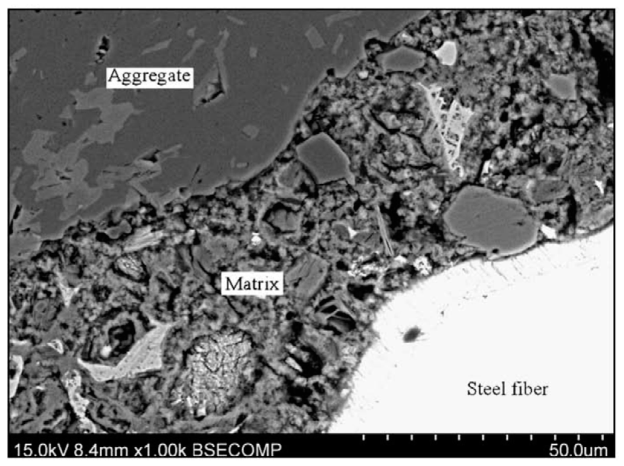
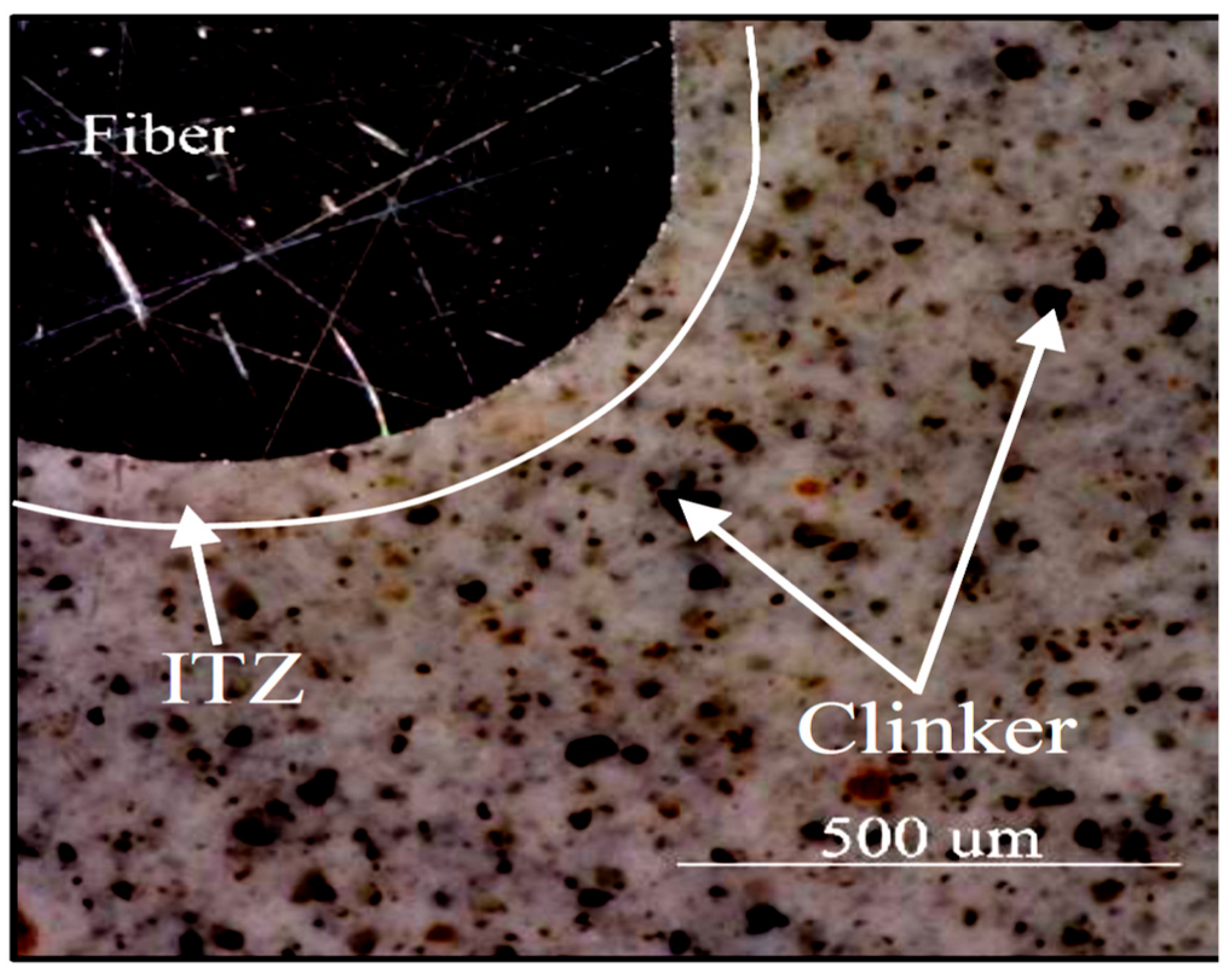
4. Fibre–Matrix Interfacial Transition Zone
5. Factors Affecting Bond Behaviour
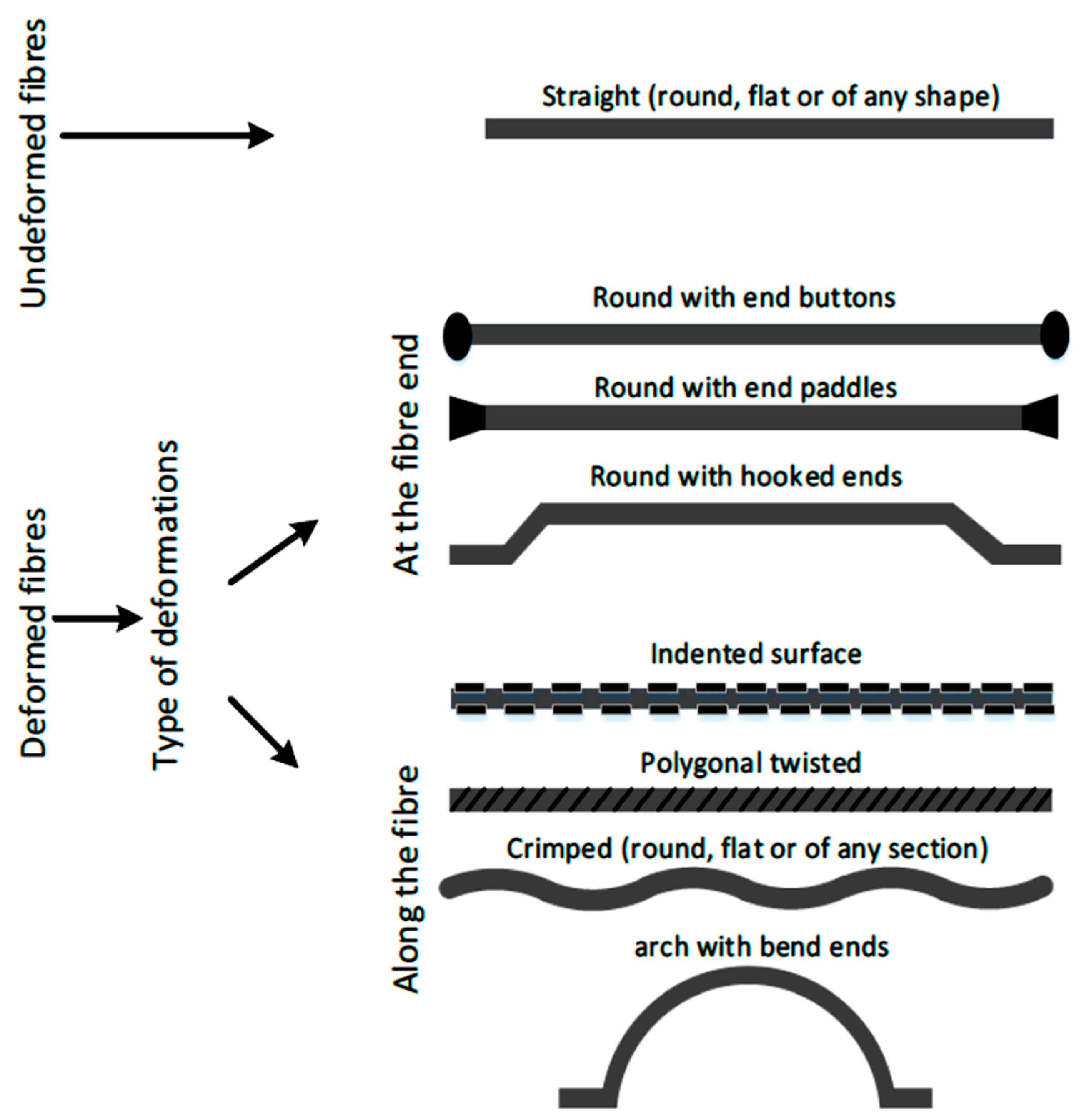
5.1. Fibre Geometry
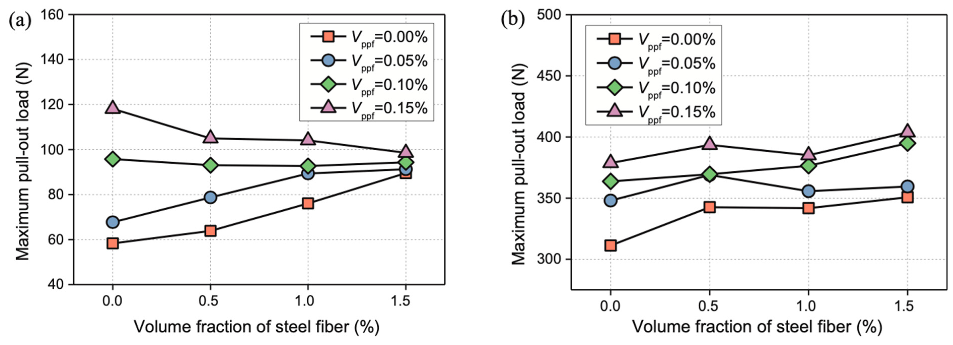
5.2. Fibre Volume Fraction
5.3. Fibre Aspect Ratio
5.4. Fibre Orientation
5.5. Fibre Embedded Length
5.6. Matrix Strength
6. Experimental Research on the Strength and Bond Characteristics of SFRC
6.1. Compressive Strength
6.2. Tensile Strength
6.3. Flexural Strength
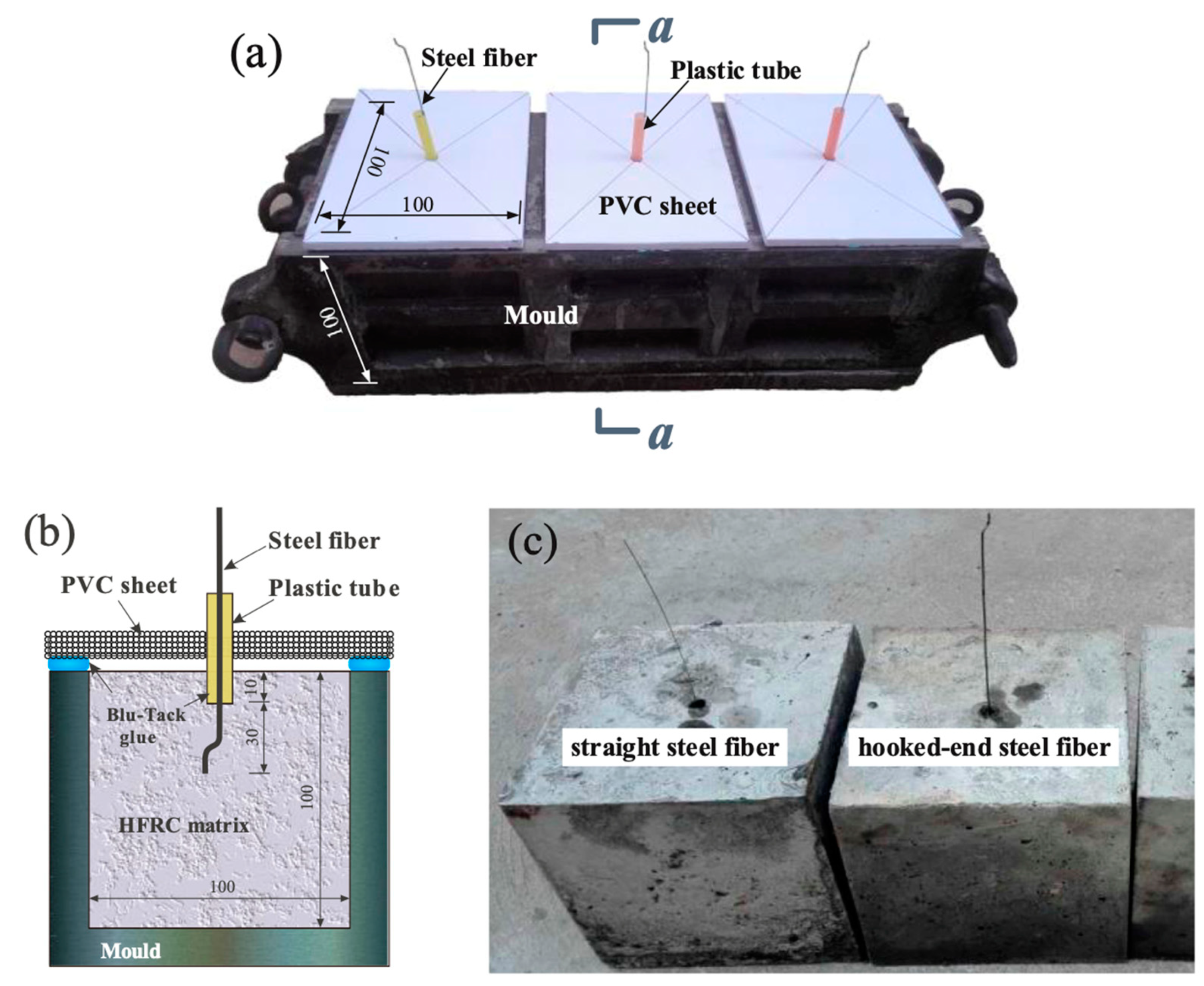
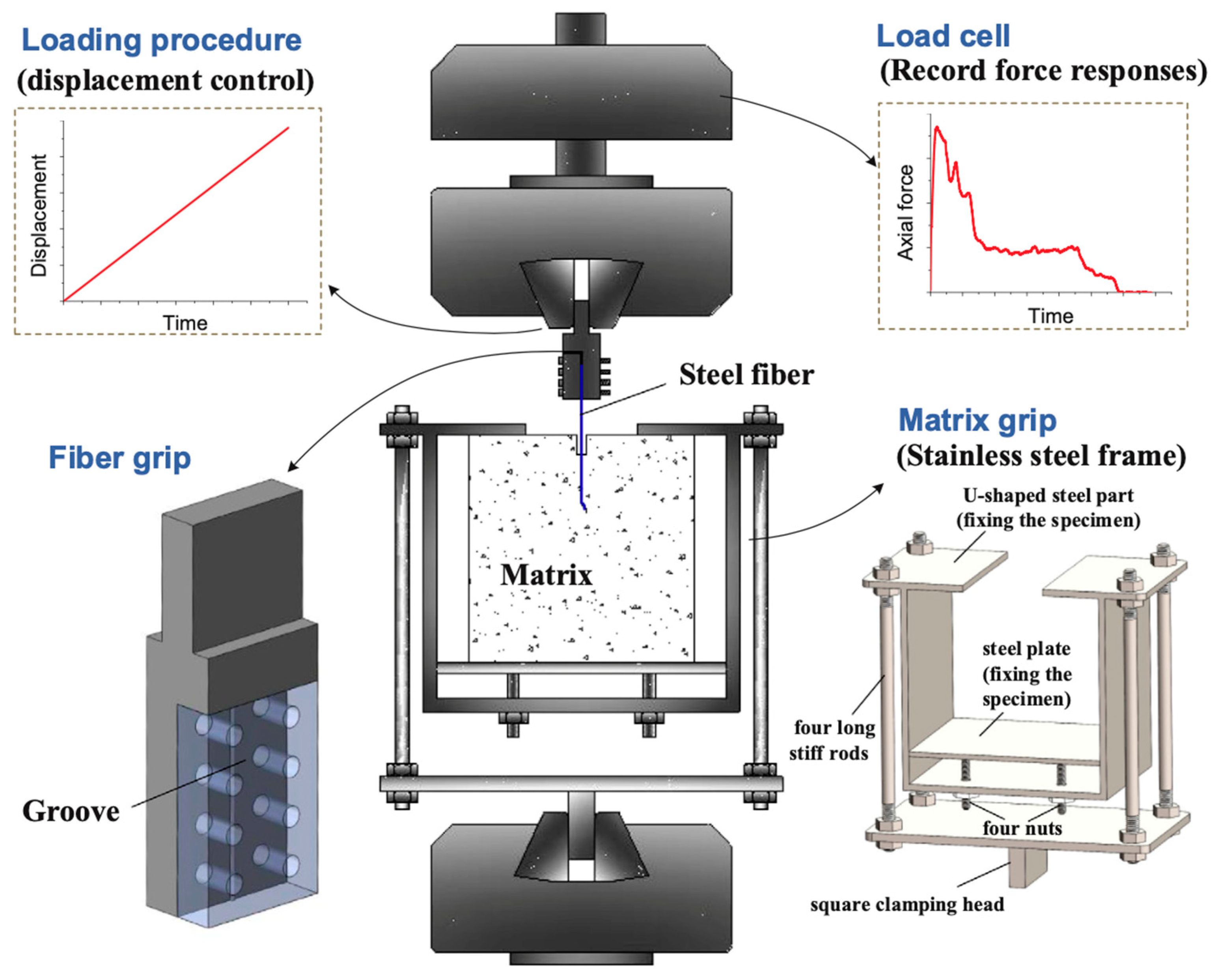
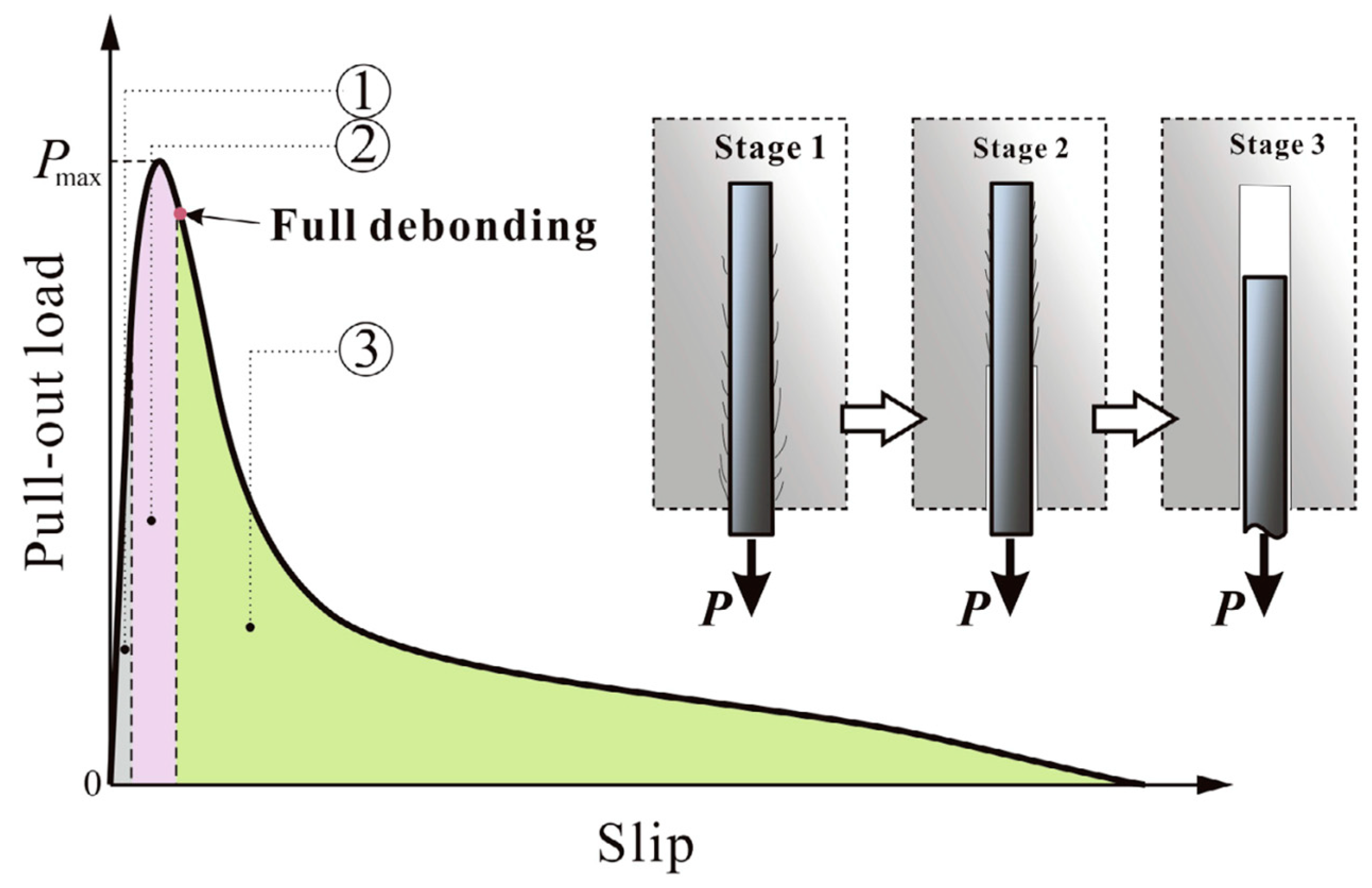
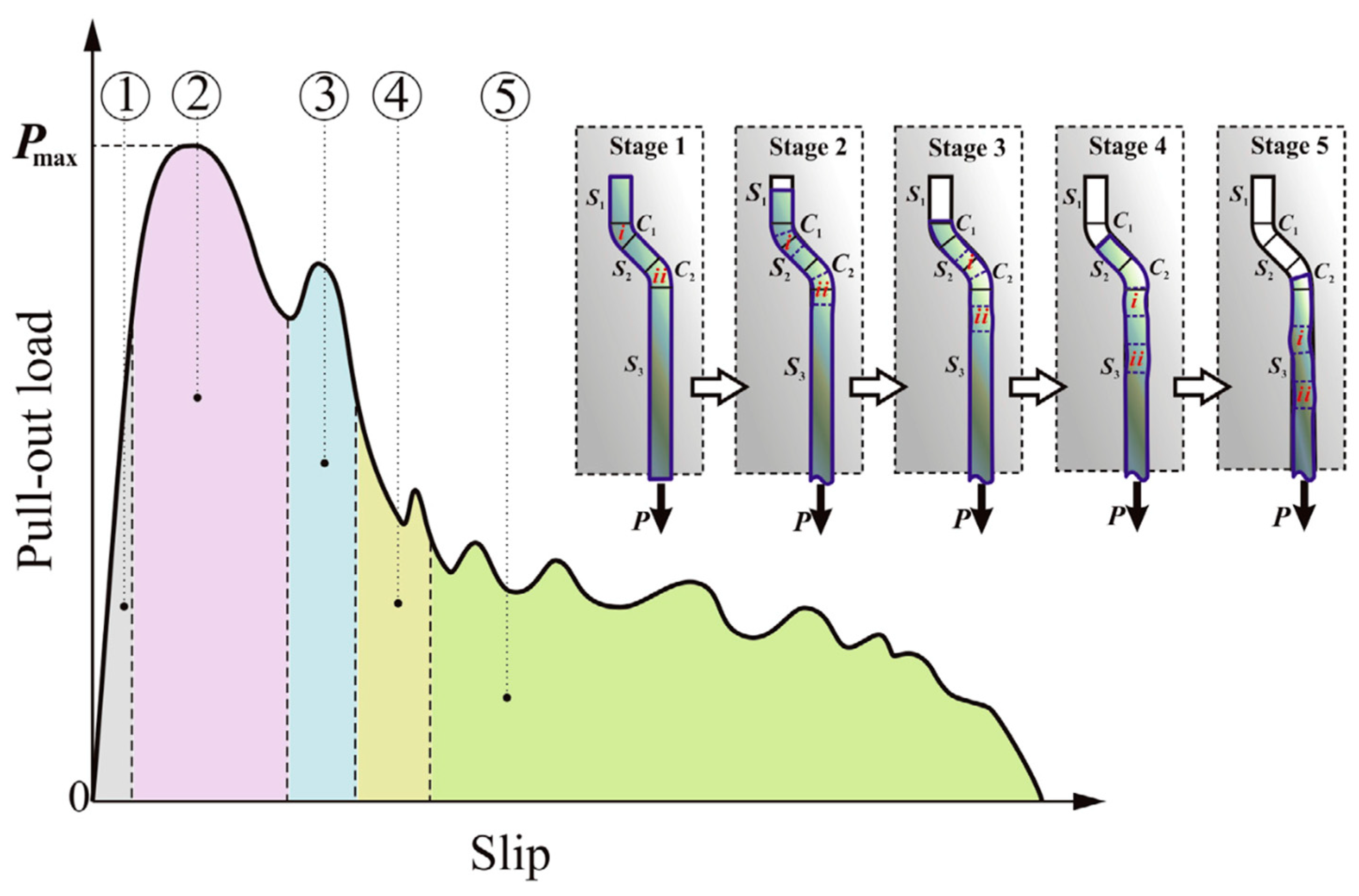
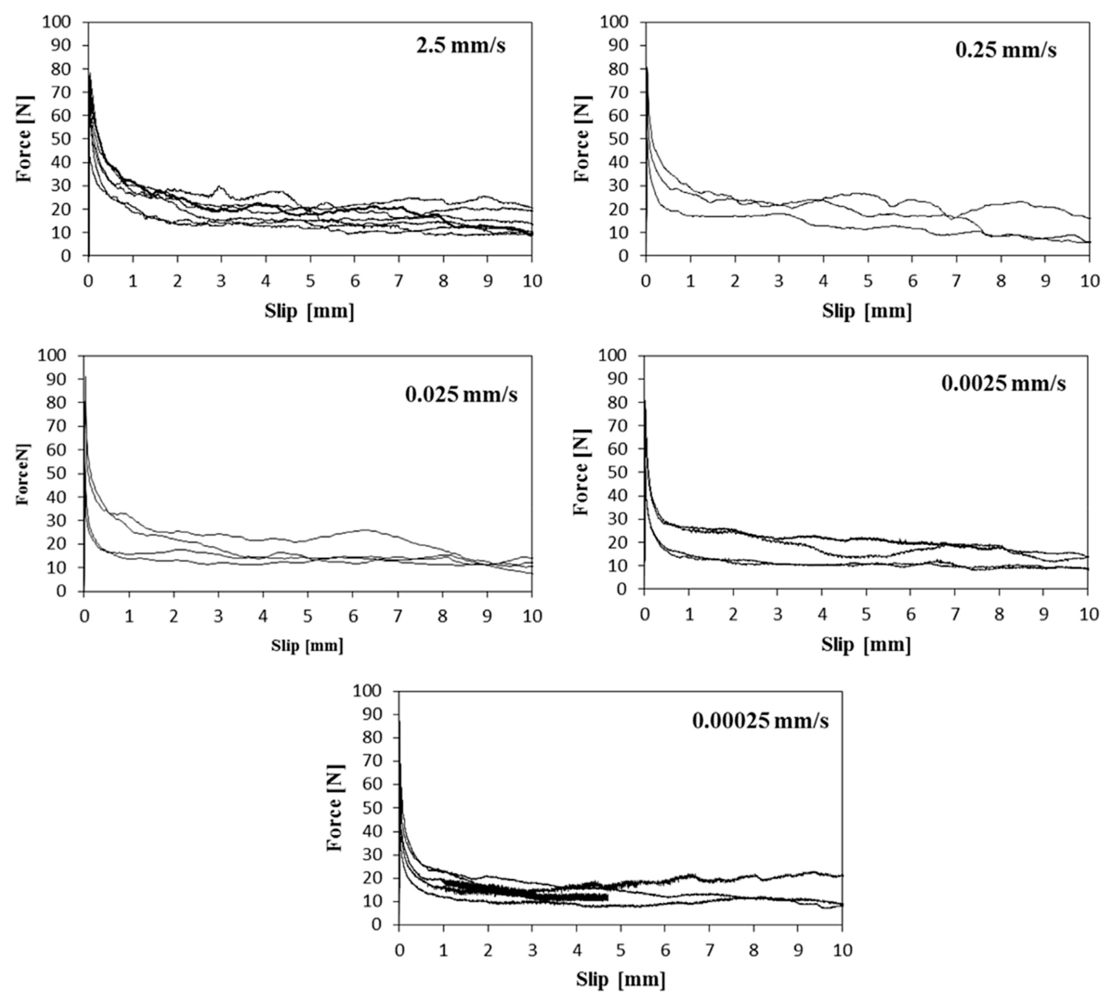
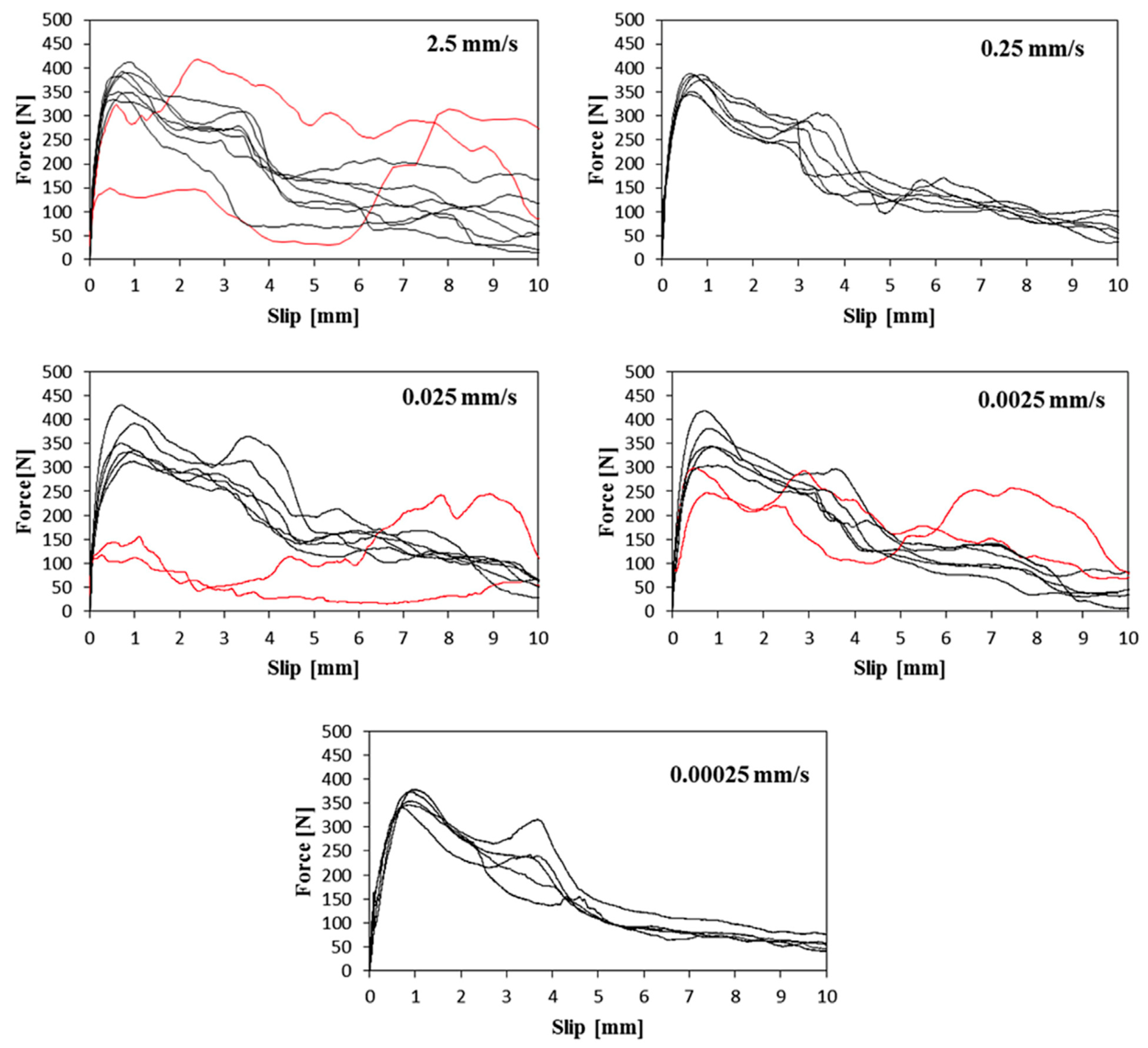
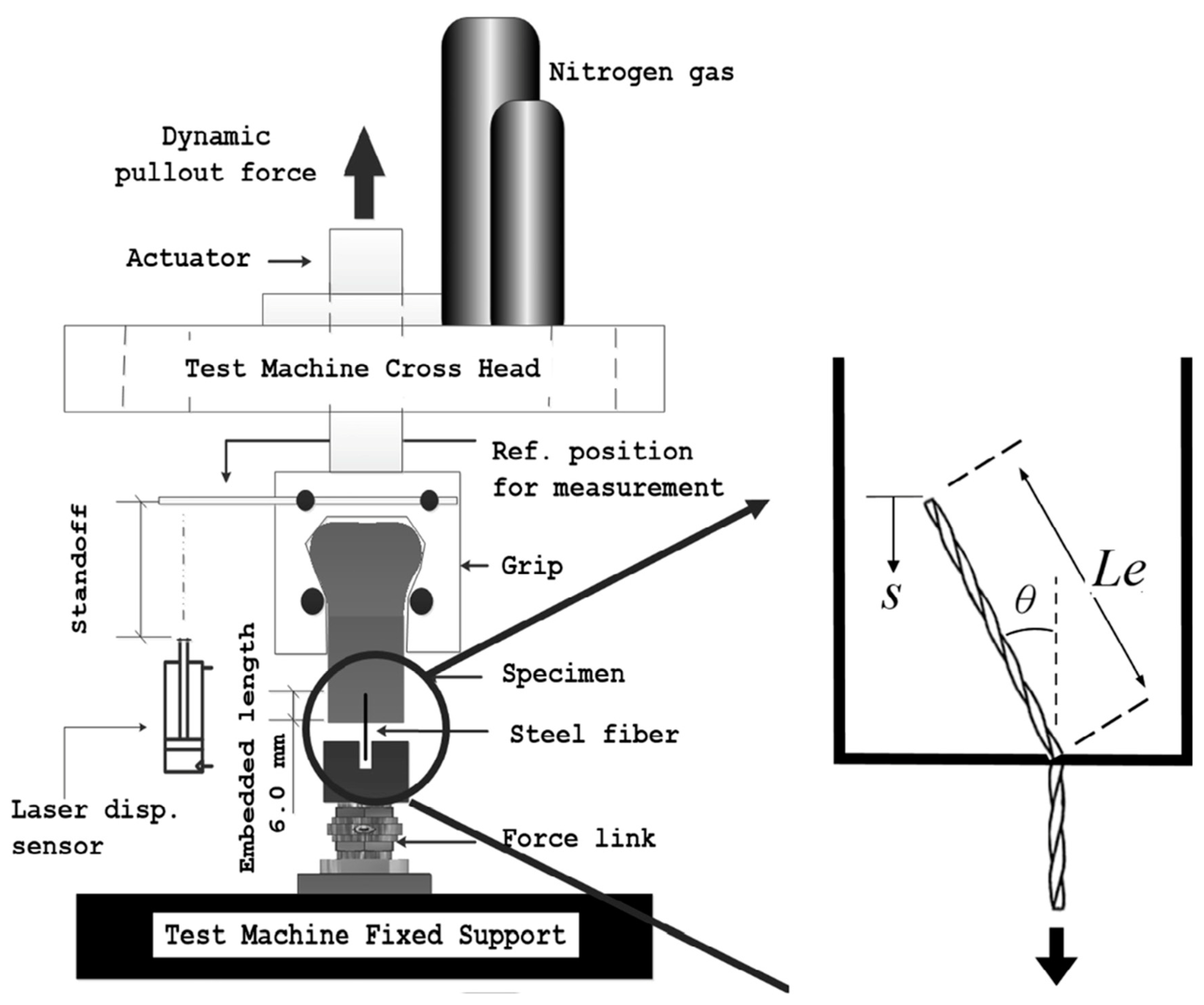
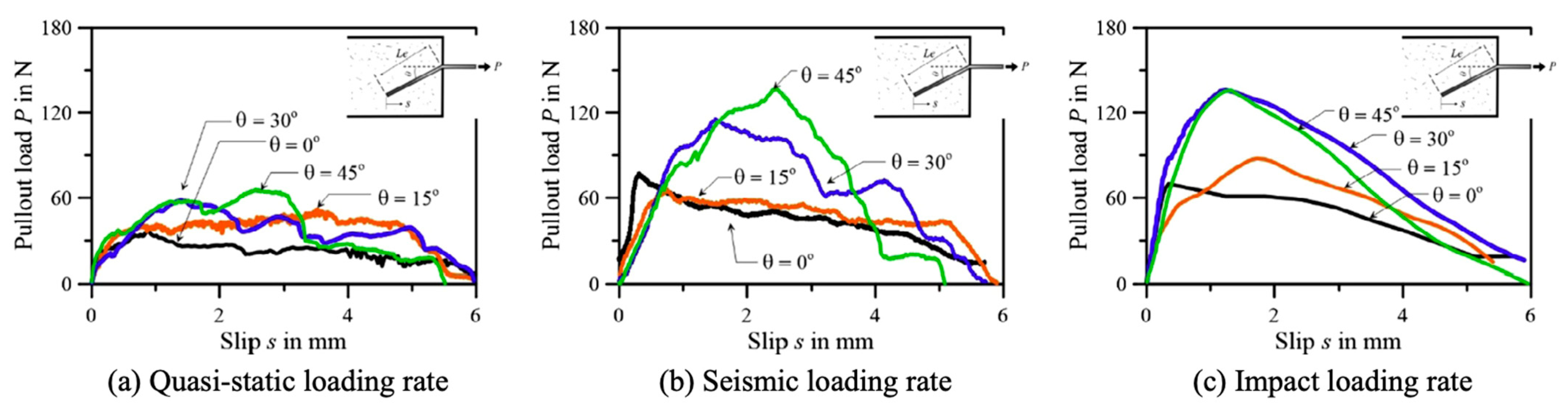
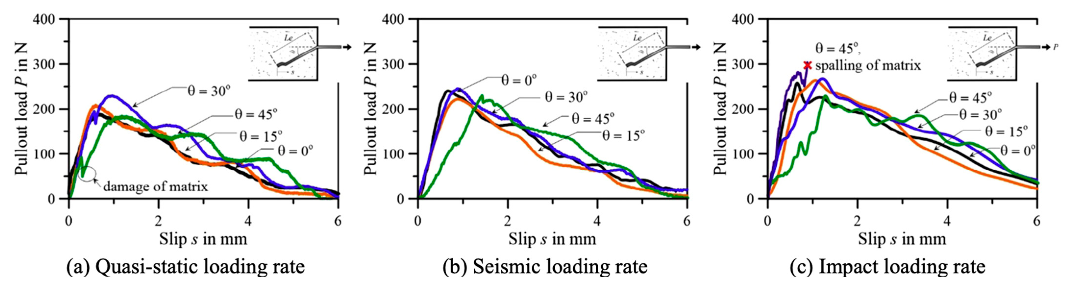
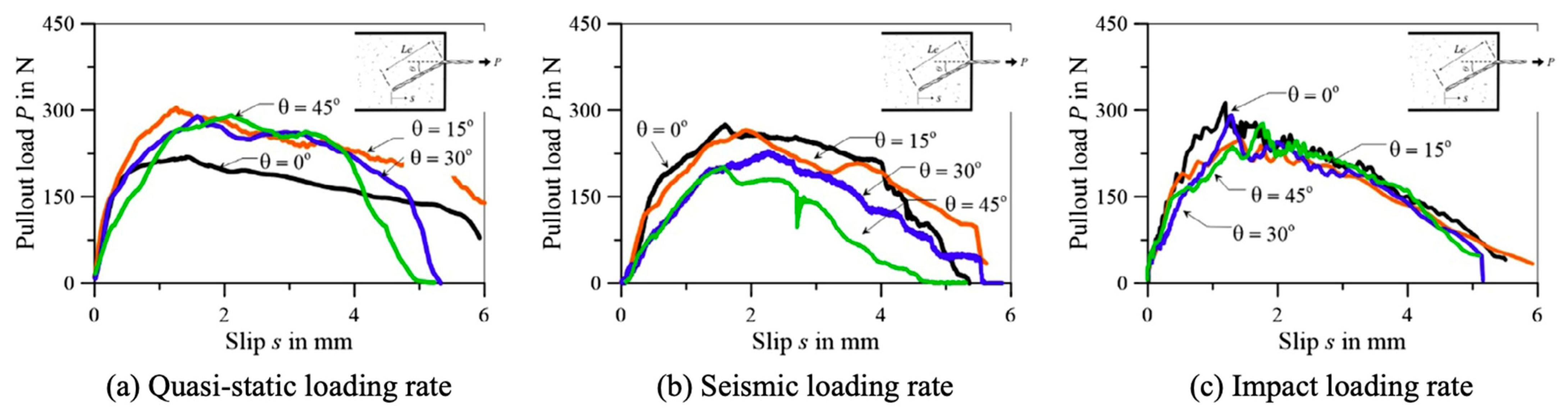
6.4. Pull-Out Behaviour of Steel Fibres
7. Conclusions and Future Perspectives
- The addition of fibres, especially steel fibres, increases the compressive strength of SFRC in general; however, the inclusion of more than 2% steel fibre is expected to result in a decrease in strength, due to decreased workability and higher pore content.
- Steel fibres have a much greater impact on improving the splitting tensile strength and flexural strength than on improving compressive strength. The strength increases as the fibre aspect ratio rises at a given fibre content. The tensile and flexural strengths of concrete containing 2.0% steel fibre have been found to be increased by up to 143 and 167%, respectively.
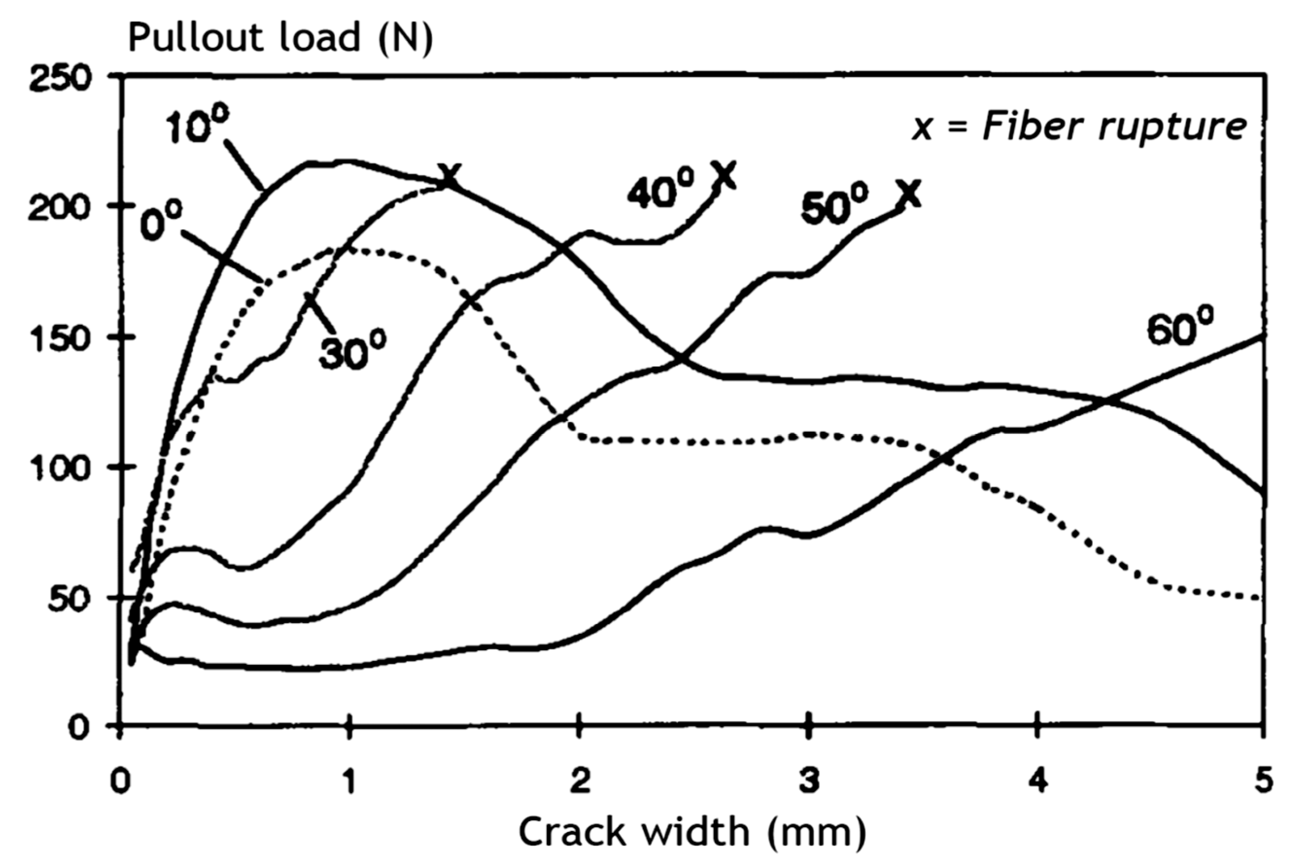
- The hook geometry of the fibre had a significant impact on its mechanical anchorage efficacy. The pull-out behaviour is directly influenced by the number of bends at the fibre ends. Even though all hooked-end fibres had the same diameter and embedded weight, there was a significant difference in their pull-out performance under hook geometry variations.
- Compared to chemical adhesion, the sliding frictional force of straight steel fibre is less susceptible to fibre addition. The addition of hybrid fibres affects mechanical hook interlocking and controls the maximum pull-out load.
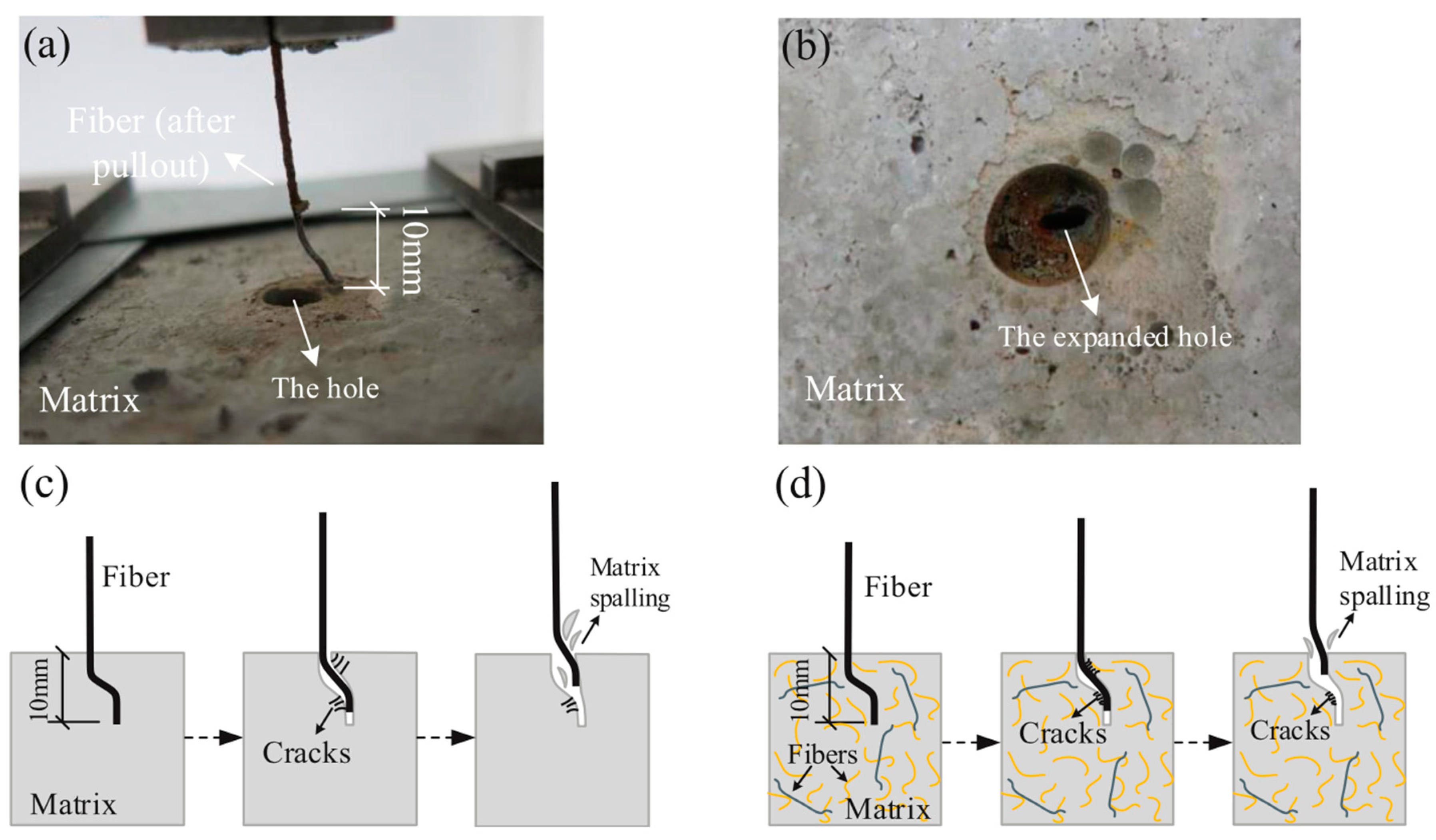
- The bonding mechanisms that control the pull-out performance of inclined fibres are very different from those that control the pull-out behaviour of aligned fibres. The maximum pull-out load and pull-out feature of inclined fibres are higher than those of aligned fibres, up to a 15° inclination angle. Nevertheless, as the inclination angle increases to 45° and beyond, the pull-out load decreases due to fibre bending and matrix spalling and all the hooked-end fibres may be ruptured.
- The loads required to pull out the deformed steel bars embedded in the specimens prepared from concretes are related to the mechanical properties of the concrete, the cover, steel fibre dosage, and the steel fibre aspect ratio.
Author Contributions
Funding
Acknowledgments
Conflicts of Interest
References
- Zollo, R.F. Fiber-reinforced concrete: An overview after 30 years of development. Cem. Concr. Compos. 1997, 19, 107–122. [Google Scholar] [CrossRef]
- Abdulhameed, A.A.; Al-Zuhairi, A.H.; Al Zaidee, S.R.; Hanoon, A.N.; Al Zand, A.W.; Hason, M.M.; Abdulhameed, H.A. The Behavior of Hybrid Fiber-Reinforced Concrete Elements: A New Stress-Strain Model Using an Evolutionary Approach. Appl. Sci. 2022, 12, 2245. [Google Scholar] [CrossRef]
- Brandt, A.M. Fibre reinforced cement-based (FRC) composites after over 40 years of development in building and civil engineering. Compos. Struct. 2008, 86, 3–9. [Google Scholar] [CrossRef]
- Abdulhameed, A.A.; Said, A.I. CFRP laminates reinforcing performance of short-span wedge-blocks segmental beams. Fibers 2020, 8, 6. [Google Scholar] [CrossRef] [Green Version]
- Abdulhameed, A.A.; Hanoon, A.N.; Abdulhameed, H.A.; Banyhussan, Q.S.; Mansi, A.S. Push-out test of steel–concrete–steel composite sections with various core materials: Behavioural study. Arch. Civ. Mech. Eng. 2021, 21, 17. [Google Scholar] [CrossRef]
- García-Taengua, E.; Martí-Vargas, J.R.; Serna, P. Bond of rebars to steel fibre reinforced concrete: Minimum concrete cover requirements to prevent splitting. In Concrete-Innovation and Design; International Federation for Structural Concrete (fib): Lausanne, Switzerland, 2015. [Google Scholar]
- Mohammadhosseini, H.; Yatim, J.M.; Sam, A.R.M.; Awal, A.A. Durability performance of green concrete composites containing waste carpet fibers and palm oil fuel ash. J. Clean. Prod. 2017, 144, 448–458. [Google Scholar] [CrossRef]
- Rossi, P.; Charron, J.P.; Bastien-Masse, M.; Tailhan, J.L.; Le Maou, F.; Ramanich, S. Tensile basic creep versus compressive basic creep at early ages: Comparison between normal strength concrete and a very high strength fibre reinforced concrete. Mater. Struct. 2014, 47, 1773–1785. [Google Scholar] [CrossRef] [Green Version]
- Garcia-Taengua, E.; Marti-Vargas, J.R.; Serna-Ros, P. Statistical Approach to Effect of Factors Involved in Bond Performance of Steel Fiber-Reinforced Concrete. Aci Struct. J. 2011, 108, 461–468. [Google Scholar]
- Yazıcı, Ş.; Arel, H.Ş. The effect of steel fiber on the bond between concrete and deformed steel bar in SFRCs. Constr. Build. Mater. 2013, 40, 299–305. [Google Scholar] [CrossRef]
- Deng, F.; Ding, X.; Chi, Y.; Xu, L.; Wang, L. The pull-out behavior of straight and hooked-end steel fiber from hybrid fiber reinforced cementitious composite: Experimental study and analytical modelling. Compos. Struct. 2018, 206, 693–712. [Google Scholar] [CrossRef]
- Zile, E.; Zile, O. Effect of the fiber geometry on the pullout response of mechanically deformed steel fibers. Cem. Concr. Res. 2013, 44, 18–24. [Google Scholar] [CrossRef]
- Frazão, C.; Barros, J.; Camões, A.; Alves, A.C.; Rocha, L. Corrosion effects on pullout behavior of hooked steel fibers in self-compacting concrete. Cem. Concr. Res. 2016, 79, 112–122. [Google Scholar] [CrossRef] [Green Version]
- Yoo, D.-Y.; Je, J.; Choi, H.-J.; Sukontasukkul, P. Influence of embedment length on the pullout behavior of steel fibers from ultra-high-performance concrete. Mater. Lett. 2020, 276, 128233. [Google Scholar] [CrossRef]
- Feng, J.; Sun, W.; Wang, X.; Shi, X. Mechanical analyses of hooked fiber pullout performance in ultra-high-performance concrete. Constr. Build. Mater. 2014, 69, 403–410. [Google Scholar] [CrossRef]
- Qi, J.; Wu, Z.; Ma, Z.J.; Wang, J. Pullout behavior of straight and hooked-end steel fibers in UHPC matrix with various embedded angles. Constr. Build. Mater. 2018, 191, 764–774. [Google Scholar] [CrossRef]
- Yoo, D.-Y.; Choi, H.-J.; Kim, S. Bond-slip response of novel half-hooked steel fibers in ultra-high-performance concrete. Constr. Build. Mater. 2019, 224, 743–761. [Google Scholar] [CrossRef]
- Soulioti, D.; Barkoula, N.-M.; Koutsianopoulos, F.; Charalambakis, N.; Matikas, T. The effect of fibre chemical treatment on the steel fibre/cementitious matrix interface. Constr. Build. Mater. 2013, 40, 77–83. [Google Scholar] [CrossRef]
- Zhang, H.; Ji, T.; Lin, X. Pullout behavior of steel fibers with different shapes from ultra-high performance concrete (UHPC) prepared with granite powder under different curing conditions. Constr. Build. Mater. 2019, 211, 688–702. [Google Scholar] [CrossRef]
- Li, L.; Li, B.; Wang, Z.; Zhang, Z.; Alselwi, O. Effects of Hybrid PVA–Steel Fibers on the Mechanical Performance of High-Ductility Cementitious Composites. Buildings 2022, 12, 1934. [Google Scholar] [CrossRef]
- Kim, B.-J.; Yi, C.; Ahn, Y.-R. Effect of embedment length on pullout behavior of amorphous steel fiber in Portland cement composites. Constr. Build. Mater. 2017, 143, 83–91. [Google Scholar] [CrossRef]
- Yoo, D.-Y.; Park, J.-J.; Kim, S.-W. Fiber pullout behavior of HPFRCC: Effects of matrix strength and fiber type. Compos. Struct. 2017, 174, 263–276. [Google Scholar] [CrossRef]
- Cao, Y.Y.Y.; Yu, Q.L. Effect of inclination angle on hooked end steel fiber pullout behavior in ultra-high performance concrete. Compos. Struct. 2018, 201, 151–160. [Google Scholar] [CrossRef]
- Yoo, D.-Y.; Kim, J.-J.; Chun, B. Dynamic pullout behavior of half-hooked and twisted steel fibers in ultra-high-performance concrete containing expansive agents. Composites. Part B Eng. 2019, 167, 517–532. [Google Scholar] [CrossRef]
- Lee, J.-H.; Kighuta, K. Twin-twist effect of fibers on the pullout resistance in cementitious materials. Constr. Build. Mater. 2017, 146, 555–562. [Google Scholar] [CrossRef]
- Tai, Y.-S.; El-Tawil, S. High loading-rate pullout behavior of inclined deformed steel fibers embedded in ultra-high performance concrete. Constr. Build. Mater. 2017, 148, 204–218. [Google Scholar] [CrossRef]
- Awal, A.A.; Mohammadhosseini, H. Green concrete production incorporating waste carpet fiber and palm oil fuel ash. J. Clean. Prod. 2016, 137, 157–166. [Google Scholar] [CrossRef]
- Kim, J.J.; Yoo, D.Y. Spacing and bundling effects on rate-dependent pullout behavior of various steel fibers embedded in ultra-high-performance concrete. Arch. Civ. Mech. Eng. 2020, 20, 46. [Google Scholar] [CrossRef] [Green Version]
- Yoo, D.-Y.; Kim, S.; Kim, J.-J.; Chun, B. An experimental study on pullout and tensile behavior of ultra-high-performance concrete reinforced with various steel fibers. Constr. Build. Mater. 2019, 206, 46–61. [Google Scholar] [CrossRef]
- Cunha, V.M.C.F.; Barros, J.A.O.; Sena-Cruz, J.M. An integrated approach for modelling the tensile behaviour of steel fibre reinforced self-compacting concrete. Cem. Concr. Res. 2011, 41, 64–76. [Google Scholar] [CrossRef] [Green Version]
- Aslani, F.; Nejadi, S. Bond characteristics of steel fiber and deformed reinforcing steel bar embedded in steel fiber reinforced self-compacting concrete (SFRSCC). Open Eng. 2012, 2, 445–470. [Google Scholar] [CrossRef]
- Abdallah, S.; Fan, M.; Cashell, K.A. Bond-slip behaviour of steel fibres in concrete after exposure to elevated temperatures. Constr. Build. Mater. 2017, 140, 542–551. [Google Scholar] [CrossRef]
- Zhang, Y.; Ju, J.W.; Chen, Q.; Yan, Z.; Zhu, H.; Jiang, Z. Characterizing and analyzing the residual interfacial behavior of steel fibers embedded into cement-based matrices after exposure to high temperatures. Compos. Part B Eng. 2020, 191, 107933. [Google Scholar] [CrossRef]
- Mohammadhosseini, H.; Alyousef, R.; Poi Ngian, S.; Tahir, M.M. Performance evaluation of sustainable concrete comprising waste polypropylene food tray fibers and palm oil fuel ash exposed to sulfate and acid attacks. Crystals 2021, 11, 966. [Google Scholar] [CrossRef]
- Chun, B.; Yoo, D.-Y. Hybrid effect of macro and micro steel fibers on the pullout and tensile behaviors of ultra-high-performance concrete. Compos. Part B Eng. 2019, 162, 344–360. [Google Scholar] [CrossRef]
- Luccioni, B.; Ruano, G.; Isla, F.; Zerbino, R.; Giaccio, G. A simple approach to model SFRC. Constr. Build. Mater. 2012, 37, 111–124. [Google Scholar] [CrossRef]
- Mohammadhosseini, H.; Alrshoudi, F.; Tahir, M.M.; Alyousef, R.; Alghamdi, H.; Alharbi, Y.R.; Alsaif, A. Durability and thermal properties of prepacked aggregate concrete reinforced with waste polypropylene fibers. J. Build. Eng. 2020, 32, 101723. [Google Scholar] [CrossRef]
- Gandomi, A.; Alavi, A.; Yun, G. Nonlinear modeling of shear strength of SFRC beams using linear genetic programming. Struct. Eng. Mech. 2011, 38, 1–25. [Google Scholar] [CrossRef]
- Zhang, W.; Lee, D.; Lee, C.; Zhang, X.; Ikechukwu, O. Bond performance of SFRC considering random distributions of aggregates and steel fibers. Constr. Build. Mater. 2021, 291, 123304. [Google Scholar] [CrossRef]
- Abdallah, S.; Fan, M.; Rees, D.W.A. Bonding Mechanisms and Strength of Steel Fiber–Reinforced Cementitious Composites: Overview. J. Mater. Civ. Eng. 2018, 30, 04018001. [Google Scholar] [CrossRef]
- Zhou, A.; Yu, Z.; Wei, H.; Tam, L.H.; Liu, T.; Zou, D. Understanding the Toughening Mechanism of Silane Coupling Agents in the Interfacial Bonding in Steel Fiber-Reinforced Cementitious Composites. ACS Appl. Mater. Interface 2020, 12, 44163–44171. [Google Scholar] [CrossRef]
- Bandelt, M.J.; Frank, T.E.; Lepech, M.D.; Billington, S.L. Bond behavior and interface modeling of reinforced high-performance fiber-reinforced cementitious composites. Cem. Concr. Compos. 2017, 83, 188–201. [Google Scholar] [CrossRef]
- Yoo, D.-Y.; Gim, J.Y.; Chun, B. Effects of rust layer and corrosion degree on the pullout behavior of steel fibers from ultra-high-performance concrete. J. Mater. Res. Technol. 2020, 9, 3632–3648. [Google Scholar] [CrossRef]
- Naaman, A.E.; Namur, G.G.; Alwan, J.M.; Najm, H.S. Fiber Pullout and Bond Slip. II: Experimental Validation. J. Struct. Eng. 1991, 117, 2791–2800. [Google Scholar] [CrossRef]
- Naaman, A.E.; Namur, G.G.; Alwan, J.M.; Najm, H.S. Fiber Pullout and Bond Slip. I: Analytical Study. J. Struct. Eng. 1991, 117, 2769–2790. [Google Scholar] [CrossRef]
- Wang, X.H.; Jacobsen, S.; He, J.Y.; Zhang, Z.L.; Lee, S.F.; Lein, H.L. Application of nanoindentation testing to study of the interfacial transition zone in steel fiber reinforced mortar. Cem. Concr. Res. 2009, 39, 701–715. [Google Scholar] [CrossRef]
- Su, Y.; Li, J.; Wu, C.; Wu, P.; Tao, M.; Li, X. Mesoscale study of steel fibre-reinforced ultra-high performance concrete under static and dynamic loads. Mater. Des. 2017, 116, 340–351. [Google Scholar] [CrossRef]
- Allison, P.; Weiss, C.; Moser, R.; Diaz, A.; Rivera, O.; Holton, S. Nanoindentation and SEM/EDX characterization of the geopolymer-to-steel interfacial transition zone for a reactive porcelain enamel coating. Compos. Part B Eng. 2015, 78, 131–137. [Google Scholar] [CrossRef]
- Xu, L.; Deng, F.; Chi, Y. Nano-mechanical behavior of the interfacial transition zone between steel-polypropylene fiber and cement paste. Constr. Build. Mater. 2017, 145, 619–638. [Google Scholar] [CrossRef]
- Zacharda, V.; Němeček, J.; Štemberk, P. Nanomechanical Performance of Interfacial Transition Zone in Fiber Reinforced Cement Matrix. Key Eng. Mater. 2018, 760, 251–256. [Google Scholar] [CrossRef]
- Zacharda, V.; Němeček, J.; Štemberk, P. Micromechanical performance of interfacial transition zone in fiber-reinforced cement matrix. IOP Conf. Ser. Mater. Sci. Eng. 2017, 246, 12018. [Google Scholar] [CrossRef]
- Feng, H.; Li, L.; Zhang, P.; Gao, D.; Zhao, J.; Feng, L.; Sheikh, M.N. Microscopic characteristics of interface transition zone between magnesium phosphate cement and steel fiber. Constr. Build. Mater. 2020, 253, 119179. [Google Scholar] [CrossRef]
- Teixeira, R.; Tonoli, G.; Santos, S.; Rayón, E.; Amigó, V.; Savastano, H.; Lahr, F.R. Nanoindentation study of the interfacial zone between cellulose fiber and cement matrix in extruded composites. Cem. Concr. Compos. 2018, 85, 1–8. [Google Scholar] [CrossRef]
- Liu, J.; Farzadnia, N.; Shi, C. Effects of superabsorbent polymer on interfacial transition zone and mechanical properties of ultra-high performance concrete. Constr. Build. Mater. 2020, 231, 117142. [Google Scholar] [CrossRef]
- Kang, S.H.; Kim, J.J.; Kim, D.J.; Chung, Y.-S. Effect of sand grain size and sand-to-cement ratio on the interfacial bond strength of steel fibers embedded in mortars. Constr. Build. Mater. 2013, 47, 1421–1430. [Google Scholar] [CrossRef]
- Wu, Z.; Shi, C.; Khayat, K.H. Influence of silica fume content on microstructure development and bond to steel fiber in ultra-high strength cement-based materials (UHSC). Cem. Concr. Compos. 2016, 71, 97–109. [Google Scholar] [CrossRef] [Green Version]
- Rossignolo, J.A.; Rodrigues, M.S.; Frias, M.; Santos, S.F.; Junior, H.S. Improved interfacial transition zone between aggregate-cementitious matrix by addition sugarcane industrial ash. Cem. Concr. Compos. 2017, 80, 157–167. [Google Scholar] [CrossRef] [Green Version]
- Zhang, L.; Zhang, Y.; Liu, C.; Liu, L.; Tang, K. Study on microstructure and bond strength of interfacial transition zone between cement paste and high-performance lightweight aggregates prepared from ferrochromium slag. Constr. Build. Mater. 2017, 142, 31–41. [Google Scholar] [CrossRef]
- Erdem, S.; Dawson, A.R.; Thom, N.H. Influence of the micro- and nanoscale local mechanical properties of the interfacial transition zone on impact behavior of concrete made with different aggregates. Cem. Concr. Res. 2012, 42, 447–458. [Google Scholar] [CrossRef]
- Mondai, P.; Shah, S.R.; Marks, L.D. Nanoscale characterization of cementitious materials. ACI Mater. J. 2008, 105, 174–179. [Google Scholar]
- Valcuende, M.; Parra, C. Bond behaviour of reinforcement in self-compacting concretes. Constr. Build. Mater. 2009, 23, 162–170. [Google Scholar] [CrossRef]
- Sharaky, I.; Torres, L.; Baena, M.; Miàs, C. An experimental study of different factors affecting the bond of NSM FRP bars in concrete. Compos. Struct. 2013, 99, 350–365. [Google Scholar] [CrossRef]
- Berrocal, C.G.; Fernandez, I.; Lundgren, K.; Lofgren, I. Corrosion-induced cracking and bond behaviour of corroded reinforcement bars in SFRC. Composites. Part B Eng. 2017, 113, 123–137. [Google Scholar] [CrossRef]
- Yuan, C.; Chen, W.; Pham, T.M.; Hao, H. Effect of aggregate size on bond behaviour between basalt fibre reinforced polymer sheets and concrete. Composites. Part B Eng. 2019, 158, 459–474. [Google Scholar] [CrossRef]
- Soulioti, D.V.; Barkoula, N.M.; Paipetis, A.; Matikas, T.E. Effects of Fibre Geometry and Volume Fraction on the Flexural Behaviour of Steel-Fibre Reinforced Concrete. Strain 2011, 47, e535–e541. [Google Scholar] [CrossRef]
- Bangi, M.R.; Horiguchi, T. Effect of fibre type and geometry on maximum pore pressures in fibre-reinforced high strength concrete at elevated temperatures. Cem. Concr. Res. 2012, 42, 459–466. [Google Scholar] [CrossRef]
- Jansson, A.; Lofgren, I.; Lundgren, K.; Gylltoft, K. Bond of reinforcement in self-compacting steel-fibre-reinforced concrete. Mag. Concr. Res. 2012, 64, 617–630. [Google Scholar] [CrossRef] [Green Version]
- Simões, T.; Octávio, C.; Valença, J.; Costa, H.; Dias-Da-Costa, D.; Júlio, E. Influence of concrete strength and steel fibre geometry on the fibre/matrix interface. Composites. Part B Eng. 2017, 122, 156–164. [Google Scholar] [CrossRef] [Green Version]
- Susetyo, J. Fibre Reinforcement for Shrinkage Crack Control in Prestressed, Precast Segmental Bridges; University of Toronto: Toronto, ON, Canada, 2009. [Google Scholar]
- Deluce, J.R. Cracking Behaviour of Steel Fibre Reinforced Concrete Containing Conventional Steel Reinforcement; University of Toronto: Toronto, ON, Canada, 2011. [Google Scholar]
- Kim, J.H.J.; Park, C.G.; Lee, S.W.; Lee, S.W.; Won, J.P. Effects of the geometry of recycled PET fiber reinforcement on shrinkage cracking of cement-based composites. Composites. Part B Eng. 2008, 39, 442–450. [Google Scholar] [CrossRef]
- Köksal, F.; Altun, F.; Yiğit, I.; Şahin, Y. Combined effect of silica fume and steel fiber on the mechanical properties of high strength concretes. Constr. Build. Mater. 2008, 22, 1874–1880. [Google Scholar] [CrossRef]
- Nili, M.; Afroughsabet, V. Combined effect of silica fume and steel fibers on the impact resistance and mechanical properties of concrete. Int. J. Impact Eng. 2010, 37, 879–886. [Google Scholar] [CrossRef] [Green Version]
- Mastali, M.; Dalvand, A. Use of silica fume and recycled steel fibers in self-compacting concrete (SCC). Constr. Build. Mater. 2016, 125, 196–209. [Google Scholar] [CrossRef]
- Soetens, T.; Van Gysel, A.; Matthys, S.; Taerwe, L. A semi-analytical model to predict the pull-out behaviour of inclined hooked-end steel fibres. Constr. Build. Mater. 2013, 43, 253–265. [Google Scholar] [CrossRef]
- Abdallah, S.; Fan, M.; Zhou, X. Effect of hooked-end steel fibres geometry on pull-out behaviour of ultra-high performance concrete. World Acad. Sci. Eng. Technol. Int. J. Civ. Environ. Struct. Constr. Archit. Eng. 2016, 10, 1530–1535. [Google Scholar]
- Hao, Y.; Hao, H. Pull-out behaviour of spiral-shaped steel fibres from normal-strength concrete matrix. Constr. Build. Mater. 2017, 139, 34–44. [Google Scholar] [CrossRef]
- Abdallah, S.; Rees, D.W.A. Comparisons Between Pull-Out Behaviour of Various Hooked-End Fibres in Normal–High Strength Concretes. Int. J. Concr. Struct. Mater. 2019, 13, 27. [Google Scholar] [CrossRef]
- Khaloo, A.R.; Kim, N. Influence of concrete and fiber characteristics on behavior of steel fiber reinforced concrete under direct shear. Aci Mater. J. 1997, 94, 592–601. [Google Scholar]
- Robins, P.; Austin, S.; Jones, P. Pull-out behaviour of hooked steel fibres. Mater. Struct. 2002, 35, 434–442. [Google Scholar] [CrossRef]
- Anbukarasi, K.; Kalaiselvam, S. Study of effect of fibre volume and dimension on mechanical, thermal, and water absorption behaviour of luffa reinforced epoxy composites. Mater. Eng. 2015, 66, 321–330. [Google Scholar] [CrossRef]
- Li, B.; Xu, L.; Shi, Y.; Chi, Y.; Liu, Q.; Li, C. Effects of fiber type, volume fraction and aspect ratio on the flexural and acoustic emission behaviors of steel fiber reinforced concrete. Constr. Build. Mater. 2018, 181, 474–486. [Google Scholar] [CrossRef]
- Marar, K.; Eren, Ö.; Roughani, H. The influence of amount and aspect ratio of fibers on shear behaviour of steel fiber reinforced concrete. KSCE J. Civ. Eng. 2017, 21, 1393–1399. [Google Scholar] [CrossRef]
- Sahin, Y.; Koksal, F. The influences of matrix and steel fibre tensile strengths on the fracture energy of high-strength concrete. Constr. Build. Mater. 2011, 25, 1801–1806. [Google Scholar] [CrossRef]
- Boulekbache, B.; Hamrat, M.; Chemrouk, M.; Amziane, S. Influence of yield stress and compressive strength on direct shear behaviour of steel fibre-reinforced concrete. Constr. Build. Mater. 2012, 27, 6–14. [Google Scholar] [CrossRef]
- Boulekbache, B.; Hamrat, M.; Chemrouk, M.; Amziane, S. Flexural behaviour of steel fibre-reinforced concrete under cyclic loading. Constr. Build. Mater. 2016, 126, 253–262. [Google Scholar] [CrossRef]
- Wang, L.; Shen, N.; Zhang, M.; Fu, F.; Qian, K. Bond performance of Steel-CFRP bar reinforced coral concrete beams. Constr. Build. Mater. 2020, 245, 118456. [Google Scholar] [CrossRef]
- Lee, S.-J.; Hong, Y.; Eom, A.-H.; Won, J.-P. Effect of steel fibres on fracture parameters of cementitious composites. Compos. Struct. 2018, 204, 658–663. [Google Scholar] [CrossRef]
- Wu, Z.; Shi, C.; He, W.; Wu, L. Effects of steel fiber content and shape on mechanical properties of ultra high performance concrete. Constr. Build. Mater. 2016, 103, 8–14. [Google Scholar] [CrossRef]
- ACI 544.1R; Report on Fiber Reinforced Concrete. American Concrete Institute-ACI Committee: Detroit, Michigan, 1996.
- Wu, Z.; Shi, C.; Khayat, K.H. Investigation of mechanical properties and shrinkage of ultra-high performance concrete: Influence of steel fiber content and shape. Composites. Part B Eng. 2019, 174, 107021. [Google Scholar] [CrossRef]
- Ashkezari, G.D.; Fotouhi, F.; Razmara, M. Experimental relationships between steel fiber volume fraction and mechanical properties of ultra-high performance fiber-reinforced concrete. J. Build. Eng. 2020, 32, 101613. [Google Scholar] [CrossRef]
- Hoang, A.L.; Fehling, E. Influence of steel fiber content and aspect ratio on the uniaxial tensile and compressive behavior of ultra high performance concrete. Constr. Build. Mater. 2017, 153, 790. [Google Scholar] [CrossRef]
- Guneyisi, E.; Gesoglu, M.; Ipek, S. Effect of steel fiber addition and aspect ratio on bond strength of cold-bonded fly ash lightweight aggregate concretes. Constr. Build. Mater. 2013, 47, 358–365. [Google Scholar] [CrossRef]
- Zhang, L.; Liu, J.; Liu, J.; Zhang, Q.; Han, F. Effect of Steel Fiber on Flexural Toughness and Fracture Mechanics Behavior of Ultrahigh-Performance Concrete with Coarse Aggregate. J. Mater. Civ. Eng. 2018, 30, 04018323. [Google Scholar] [CrossRef]
- Dupont, D.; Vandewalle, L. Distribution of steel fibres in rectangular sections. Cem. Concr. Compos. 2005, 27, 391–398. [Google Scholar] [CrossRef]
- Huang, H.; Gao, X.; Li, L.; Wang, H. Improvement effect of steel fiber orientation control on mechanical performance of UHPC. Constr. Build. Mater. 2018, 188, 709–721. [Google Scholar] [CrossRef]
- Soroushian, P.; Lee, C.-D. Distribution and orientation of fibers in steel fiber reinforced concrete. Mater. J. 1990, 87, 433–439. [Google Scholar]
- Laranjeira, F.; Grünewald, S.; Walraven, J.; Blom, C.; Molins, C.; Aguado, A. Characterization of the orientation profile of steel fiber reinforced concrete. Mater. Struct. 2011, 44, 1093–1111. [Google Scholar] [CrossRef]
- Mudadu, A.; Tiberti, G.; Germano, F.; Plizzari, G.A.; Morbi, A. The effect of fiber orientation on the post-cracking behavior of steel fiber reinforced concrete under bending and uniaxial tensile tests. Cem. Concr. Compos. 2018, 93, 274–288. [Google Scholar] [CrossRef]
- Nieuwoudt, P.D.; Boshoff, W.P. Time-dependent pull-out behaviour of hooked-end steel fibres in concrete. Cem. Concr. Compos. 2017, 79, 133–147. [Google Scholar] [CrossRef]
- Marcos-Meson, V.; Solgaard, A.; Fischer, G.; Edvardsen, C.; Michel, A. Pull-out behaviour of hooked-end steel fibres in cracked concrete exposed to wet-dry cycles of chlorides and carbon dioxide—Mechanical performance. Constr. Build. Mater. 2020, 240, 117764. [Google Scholar] [CrossRef]
- de Oliveira, F.L. Design-Oriented Constitutive Model for Steel Fiber Reinforced Concrete; Universitat Politècnica de Catalunya: Barcelona, Spain, 2010. [Google Scholar]
- Marković, I. High-Performance Hybrid-Fibre Concrete: Development and Utilisation; IOS Press: Amsterdam, The Netherlands, 2006. [Google Scholar]
- Breitenbücher, R.; Meschke, T.G.; Song, M.F.; Zhan, M.Y. Experimental, analytical and numerical analysis of the pullout behaviour of steel fibres considering different fibre types, inclinations and concrete strengths. Struct. Concr. 2014, 15, 126–135. [Google Scholar] [CrossRef]
- Abdallah, S.; Fan, M.; Zhou, X. Pull-Out Behaviour of Hooked End Steel Fibres Embedded in Ultra-high Performance Mortar with Various W/B Ratios. Int. J. Concr. Struct. Mater. 2017, 11, 301–313. [Google Scholar] [CrossRef]
- Thomas, J.; Ramaswamy, A. Mechanical Properties of Steel Fiber-Reinforced Concrete. J. Mater. Civ. Eng. 2007, 19, 385–392. [Google Scholar] [CrossRef]
- Silva, F.d.A.; Mobasher, B.; Filho, R.D.T. Cracking mechanisms in durable sisal fiber reinforced cement composites. Cem. Concr. Compos. 2009, 31, 721–730. [Google Scholar] [CrossRef]
- Pujadas, P.; Blanco, A.; Cavalaro, S.H.P.; De La Fuente, A.; Aguado, A. The need to consider flexural post-cracking creep behavior of macro-synthetic fiber reinforced concrete. Constr. Build. Mater. 2017, 149, 790–800. [Google Scholar] [CrossRef]
- Llano-Torre, A.; Arango, S.E.; García-Taengua, E.; Martí-Vargas, J.R.; Serna, P. Influence of fibre reinforcement on the long-term behaviour of cracked concrete. In Creep Behaviour in Cracked Sections of Fibre Reinforced Concrete; Springer: Berlin/Heidelberg, Germany, 2017; pp. 195–209. [Google Scholar]
- García-Taengua, E.; Mas, L.; Martí Vargas, J.R.; Ros, P.S. New Views on the Study of Variables Affecting Bond of Reinforcing Bars to Steel Fiber Reinforced Concrete. In Proceedings of the 8th RILEM International Symposium on Fibre Reinforced Concrete: Challenges and Opportunities (BEFIB 2012), Guimarães, Portugal, 19–21 September 2012; RILEM Publications SARL: Marne, France, 2012. [Google Scholar]
- Torre-Casanova, A.; Jason, L.; Davenne, L.; Pinelli, X. Confinement effects on the steel–concrete bond strength and pull-out failure. Eng. Fract. Mech. 2013, 97, 92–104. [Google Scholar] [CrossRef]
- Tattersall, G.; Urbanowicz, C. Bond strength in steel-fibre-reinforced concrete. Mag. Concr. Res. 1974, 26, 105–113. [Google Scholar] [CrossRef]
- Chan, Y.-W.; Chu, S.-H. Effect of silica fume on steel fiber bond characteristics in reactive powder concrete. Cem. Concr. Res. 2004, 34, 1167–1172. [Google Scholar] [CrossRef]
- Nazarimofrad, E.; Shaikh, F.U.A.; Nili, M. Effects of steel fibre and silica fume on impact behaviour of recycled aggregate concrete. J. Sustain. Cem. Based Mater. 2017, 6, 54–68. [Google Scholar] [CrossRef]
- Shaikh, F.U.A.; Shafaei, Y.; Sarker, P.K. Effect of nano and micro-silica on bond behaviour of steel and polypropylene fibres in high volume fly ash mortar. Constr. Build. Mater. 2016, 115, 690–698. [Google Scholar] [CrossRef] [Green Version]
- Xu, L.; Wu, F.; Chi, Y.; Cheng, P.; Zeng, Y.; Chen, Q. Effects of coarse aggregate and steel fibre contents on mechanical properties of high performance concrete. Constr. Build. Mater. 2019, 206, 97. [Google Scholar] [CrossRef]
- Huang, C.; Zhao, G. Properties of steel fibre reinforced concrete containing larger coarse aggregate. Cem. Concr. Compos. 1995, 17, 199–206. [Google Scholar] [CrossRef]
- Liu, J.; Han, F.; Cui, G.; Zhang, Q.; Lv, J.; Zhang, L.; Yang, Z. Combined effect of coarse aggregate and fiber on tensile behavior of ultra-high performance concrete. Constr. Build. Mater. 2016, 121, 310–318. [Google Scholar] [CrossRef]
- Larsen, I.L.; Thorstensen, R.T. The influence of steel fibres on compressive and tensile strength of ultra high performance concrete: A review. Constr. Build. Mater. 2020, 256, 119459. [Google Scholar] [CrossRef]
- Song, P.S.; Hwang, S. Mechanical properties of high-strength steel fiber-reinforced concrete. Constr. Build. Mater. 2004, 18, 669–673. [Google Scholar] [CrossRef]
- Ding, Y.; You, Z.; Jalali, S. The composite effect of steel fibres and stirrups on the shear behaviour of beams using self-consolidating concrete. Eng. Struct. 2011, 33, 107–117. [Google Scholar] [CrossRef]
- Eren, Ö.; Marar, K. Effects of limestone crusher dust and steel fibers on concrete. Constr. Build. Mater. 2009, 23, 981–988. [Google Scholar] [CrossRef]
- Köksal, F.; Şahin, Y.; Gencel, O.; Yiğit, I. Fracture energy-based optimisation of steel fibre reinforced concretes. Eng. Fract. Mech. 2013, 107, 29–37. [Google Scholar] [CrossRef]
- Shafaei, Y.; Shaikh, F.U.A.; Sarker, P.K. Effect of the Fibre Geometry on Pull-out Behaviour of HVFA Mortar Containing Nanosilica. Procedia Eng. 2017, 171, 1535–1541. [Google Scholar] [CrossRef]
- Abdallah, S.; Fan, M.; Rees, D.W.A. Analysis and modelling of mechanical anchorage of 4D/5D hooked end steel fibres. Mater. Des. 2016, 112, 539–552. [Google Scholar] [CrossRef] [Green Version]
- Afroughsabet, V.; Biolzi, L.; Ozbakkaloglu, T. High-performance fiber-reinforced concrete: A review. J. Mater. Sci. 2016, 51, 6517–6551. [Google Scholar] [CrossRef] [Green Version]
- Zain, M.; Mahmud, H.; Ilham, A.; Faizal, M. Prediction of splitting tensile strength of high-performance concrete. Cem. Concr. Res. 2002, 32, 1251–1258. [Google Scholar] [CrossRef]
- Li, Z. Advanced Concrete Technology; Wiley: Hoboken, NJ, USA, 2011. [Google Scholar]
- Alhozaimy, A.M.; Soroushian, P.; Mirza, F. Mechanical properties of polypropylene fiber reinforced concrete and the effects of pozzolanic materials. Cem. Concr. Compos. 1996, 18, 85–92. [Google Scholar] [CrossRef]
- Hsie, M.; Tu, C.; Song, P.S. Mechanical properties of polypropylene hybrid fiber-reinforced concrete. Mater. Sci. Eng. A Struct. Mater. Prop. Microstruct. Process 2008, 494, 153–157. [Google Scholar] [CrossRef]
- Oluokun, F.A.; Burdette, E.G.; Deatherage, J.H. Splitting tensile-strength and compressive strength relationship at early ages. Aci Mater. J. 1991, 88, 115–121. [Google Scholar]
- Choi, Y.; Yuan, R.L. Experimental relationship between splitting tensile strength and compressive strength of GFRC and PFRC. Cem. Concr. Res. 2005, 35, 1587–1591. [Google Scholar] [CrossRef]
- Murali, G.; Santhi, A.S.; Ganesh, G.M. Impact resistance and strength reliability of fiber reinforced concrete using two parameter weibull distribution. J. Eng. Appl. Sci. 2014, 9, 554–559. [Google Scholar]
- Lu, X.; Hsu, C.-T.T. Behavior of high strength concrete with and without steel fiber reinforcement in triaxial compression. Cem. Concr. Res. 2006, 36, 1679–1685. [Google Scholar] [CrossRef]
- Sivakumar, A.; Santhanam, M. Mechanical properties of high strength concrete reinforced with metallic and non-metallic fibres. Cem. Concr. Compos. 2007, 29, 603–608. [Google Scholar] [CrossRef]
- Wang, H.T.; Wang, L.C. Experimental study on static and dynamic mechanical properties of steel fiber reinforced lightweight aggregate concrete. Constr. Build. Mater. 2013, 38, 1146–1151. [Google Scholar] [CrossRef]
- Yazıcı, Ş.; İnan, G.; Tabak, V. Effect of aspect ratio and volume fraction of steel fiber on the mechanical properties of SFRC. Constr. Build. Mater. 2007, 21, 1250–1253. [Google Scholar] [CrossRef]
- Abbass, W.; Khan, M.I.; Mourad, S. Evaluation of mechanical properties of steel fiber reinforced concrete with different strengths of concrete. Constr. Build. Mater. 2018, 168, 556. [Google Scholar] [CrossRef]
- Yap, S.P.; Bu, C.H.; Alengaram, U.J.; Mo, K.H.; Jumaat, M.Z. Flexural toughness characteristics of steel–polypropylene hybrid fibre-reinforced oil palm shell concrete. Mater. Eng. 2014, 57, 652–659. [Google Scholar] [CrossRef]
- Mo, K.H.; Yap, K.K.Q.; Alengaram, U.J.; Jumaat, M.Z. The effect of steel fibres on the enhancement of flexural and compressive toughness and fracture characteristics of oil palm shell concrete. Constr. Build. Mater. 2014, 55, 20–28. [Google Scholar] [CrossRef]
- Wang, J.-Y.; Chia, K.-S.; Liew, R.; Zhang, M.-H. Flexural performance of fiber-reinforced ultra lightweight cement composites with low fiber content. Cem. Concr. Compos. 2013, 43, 39–47. [Google Scholar] [CrossRef]
- Balaguru, R.; Najm, H. High-performance fiber-reinforced concrete mixture proportions with high fiber volume fractions. Aci Mater. J. 2004, 101, 281–286. [Google Scholar]
- Soroushian, P.; Bayasi, Z. Fiber type effects on the performance of steel fiber reinforced concrete. Mater. J. 1991, 88, 129–134. [Google Scholar]
- Abu-Lebdeh, T.; Hamoush, S.; Heard, W.; Zornig, B. Effect of matrix strength on pullout behavior of steel fiber reinforced very-high strength concrete composites. Constr. Build. Mater. 2011, 25, 39–46. [Google Scholar] [CrossRef]
- Isla, F.; Ruano, G.; Luccioni, B. Analysis of steel fibers pull-out. Experimental study. Constr. Build. Mater. 2015, 100, 183–193. [Google Scholar] [CrossRef]


Publisher’s Note: MDPI stays neutral with regard to jurisdictional claims in published maps and institutional affiliations. |
© 2022 by the authors. Licensee MDPI, Basel, Switzerland. This article is an open access article distributed under the terms and conditions of the Creative Commons Attribution (CC BY) license (https://creativecommons.org/licenses/by/4.0/).
Share and Cite
Mujalli, M.A.; Dirar, S.; Mushtaha, E.; Hussien, A.; Maksoud, A. Evaluation of the Tensile Characteristics and Bond Behaviour of Steel Fibre-Reinforced Concrete: An Overview. Fibers 2022, 10, 104. https://doi.org/10.3390/fib10120104
Mujalli MA, Dirar S, Mushtaha E, Hussien A, Maksoud A. Evaluation of the Tensile Characteristics and Bond Behaviour of Steel Fibre-Reinforced Concrete: An Overview. Fibers. 2022; 10(12):104. https://doi.org/10.3390/fib10120104
Chicago/Turabian StyleMujalli, Mohammed A., Samir Dirar, Emad Mushtaha, Aseel Hussien, and Aref Maksoud. 2022. "Evaluation of the Tensile Characteristics and Bond Behaviour of Steel Fibre-Reinforced Concrete: An Overview" Fibers 10, no. 12: 104. https://doi.org/10.3390/fib10120104