
Nanofibres in Drug Delivery Applications


Abstract
:
1. Introduction
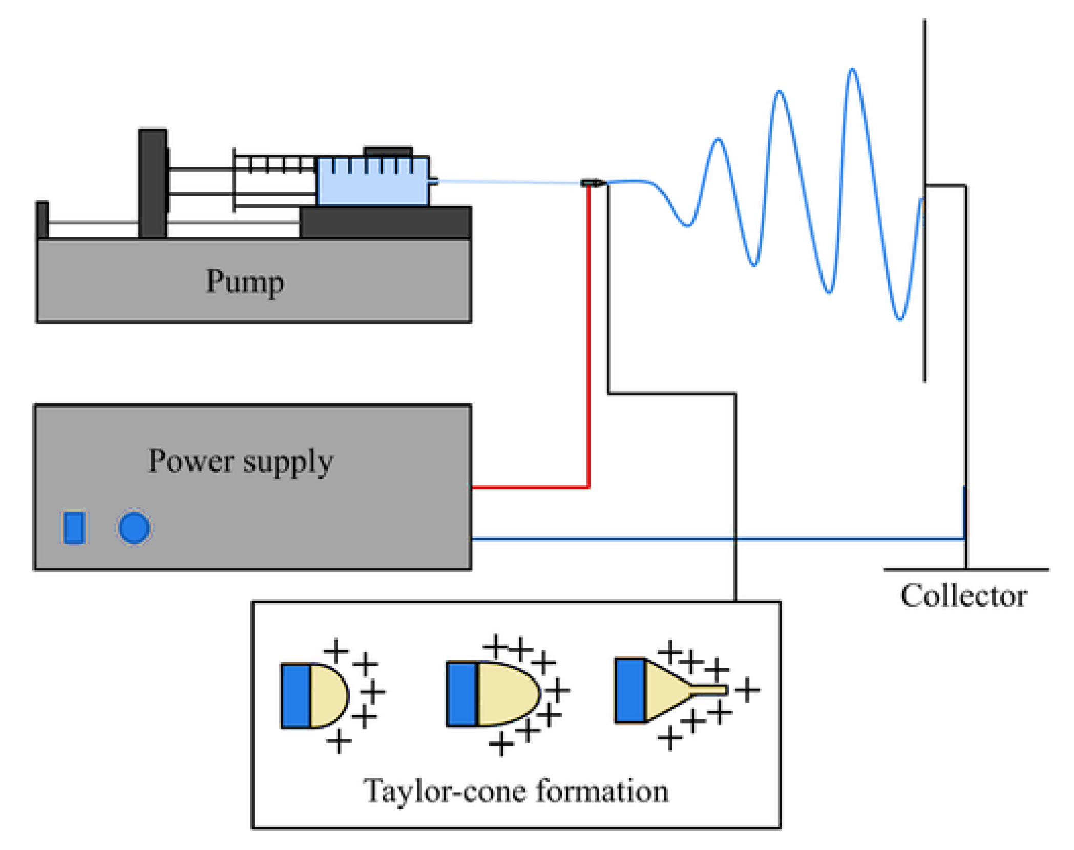
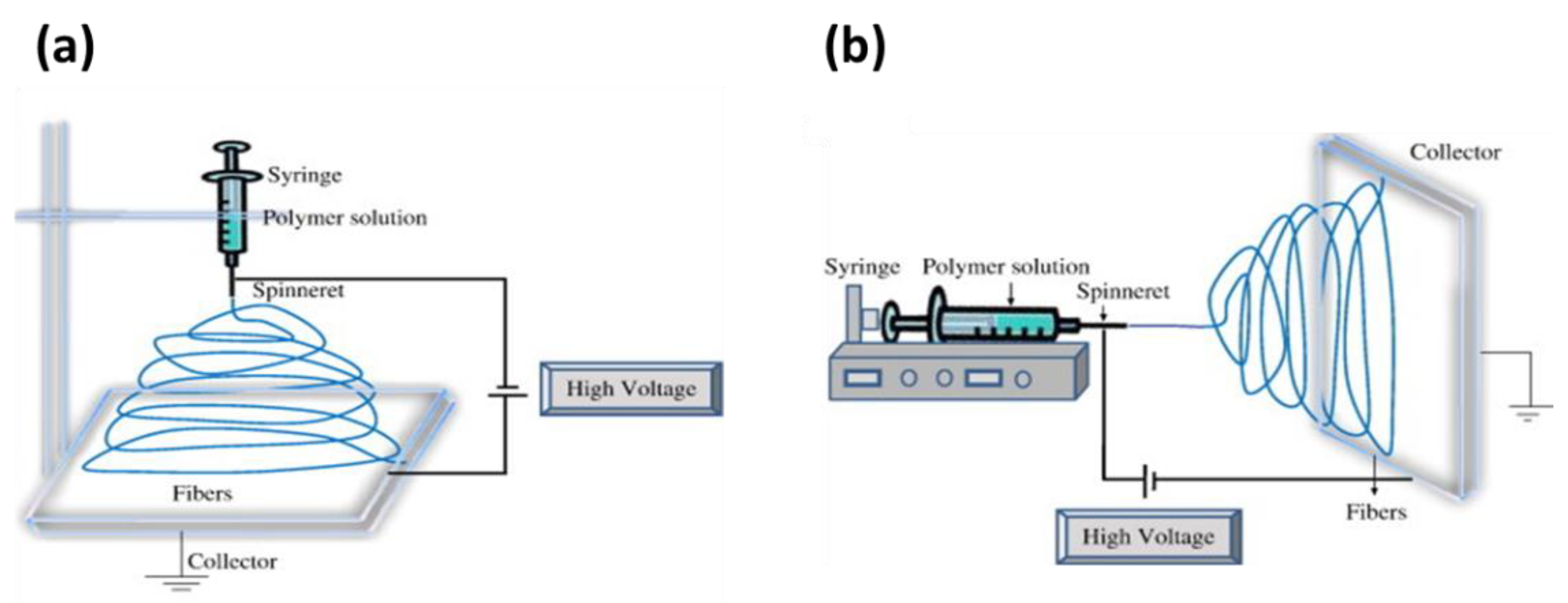
2. Electrospinning
2.1. Factors Affecting the Electrospinning Process
2.1.1. Effect of Process Parameters
Effect of Applied Voltage
Effect of Flow Rate
Effect of Distance between Needle and the Collector

| Parameters | Effect on Fibre Morphology |
|---|---|
| Increases in applied voltage | Increase/decrease in fibre diameter |
| Increase in flow rate | Increase in fibre diameter also leads to (beads on fibre) in case of high flow rate |
| Increase distance from needle to collector | Electric field unstable, difficulties in performing process |
| Concentration of polymer | Increase in fibre diameter with increase in concentration |
| Viscosity | Low generation of beads, high increase in fibre diameter |
| Solution conductivity | Decrease in fibre diameter with increase in concentration |
| Solvent volatility | Fibres exhibit micro texture (pores on the surface of fibres, which increase their surface area) |
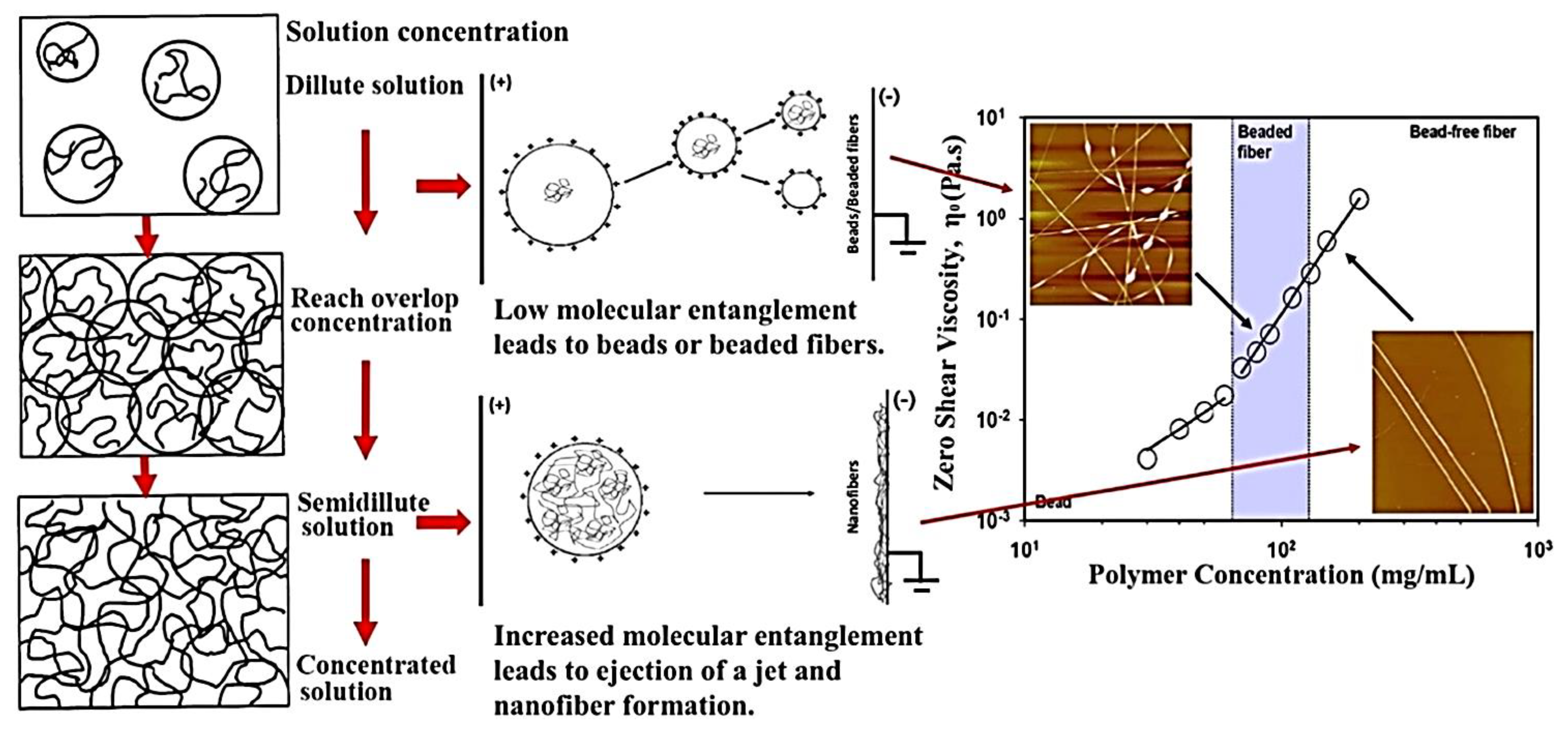
2.1.2. Solution Parameters
2.1.3. Ambient Conditions
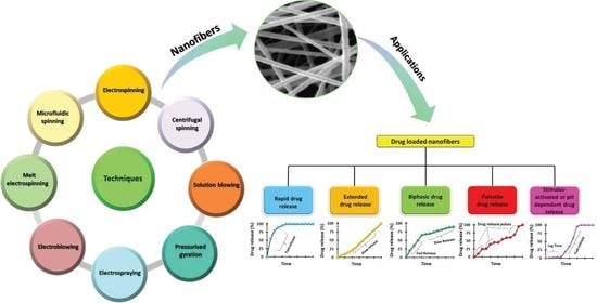
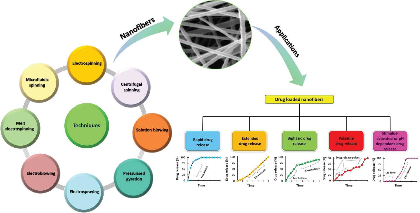
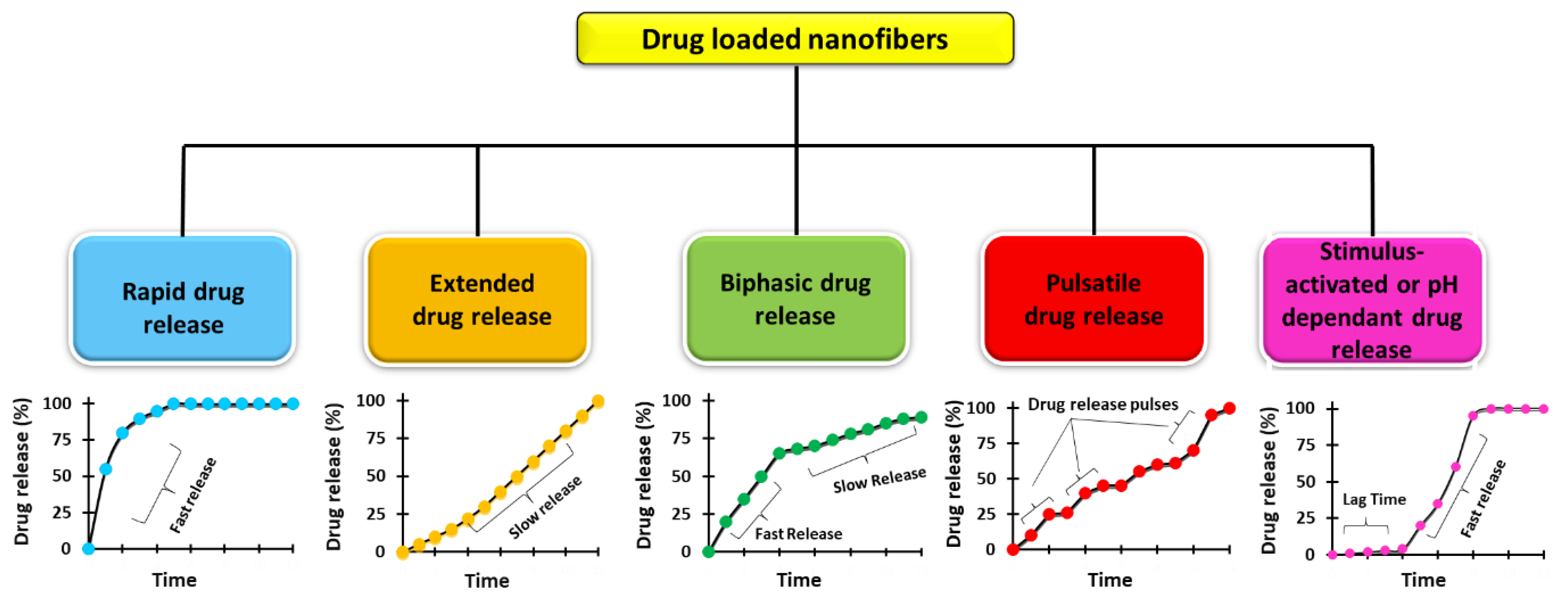
3. Types of Electrospinning Techniques and Their Applications in Drug Delivery
3.1. Monoaxial Electrospinning
Application of Monoaxial Electrospinning in Drug Delivery
| Drug(s) | Polymer(s) | Solvent(s) | Drug Release Characteristics | Reference |
|---|---|---|---|---|
| Vancomycin | Chitosan and gelatin | Glacial acetic acid and water | Sustained drug release | [75] |
| Levofloxacillin | Bletilla striata and PCL | DCM and DMF | Sustained drug release | [76] |
| Indomethacin | Eudragit RS100 and Eudragit S100 | Ethanol | pH-controlled drug release | [84] |
| Doxorubicin | PEO and PLA | 2,2,2-Trifluoroethanol | Biphasic release | [77] |
| 5-fluorouracil | Polycaprolactone and chitosan | Formic acid/acetic acid solution | Sustained drug release | [78] |
| 5-fluorouracil | Polycaprolactone and gelatin | Acetic acid and Formic acid | Controlled drug release | [89] |
| Tetracycline hydrochloride | PVA and Chitosan | Water and acetic acid solution | Initial burst followed by sustained release | [99] |
| Ciprofloxacin | PLCL and PNIPAAm | HFIP | Thermosensitive drug release | [102] |
| Gentamicin | Chitosan and alginate | Acetic acid and DI water | - | [100] |
| Moxifloxacin | Chitosan and PEO | DI Water | - | [101] |
| Timolol maleate | PVP and (PNIPAM) | Ethanol | Triphasic drug release | [82] |
| Ferulic Acid | Hyaluronan and PVP | Ethanol and Water | Burst release | [83] |
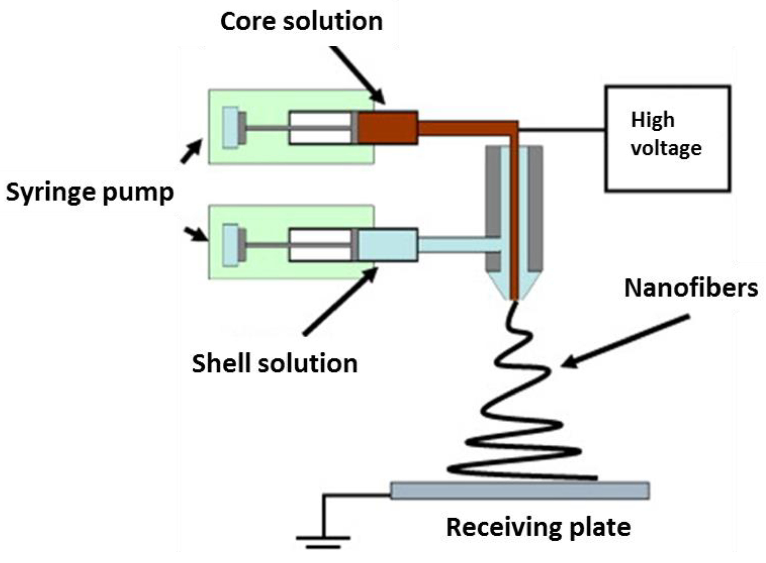
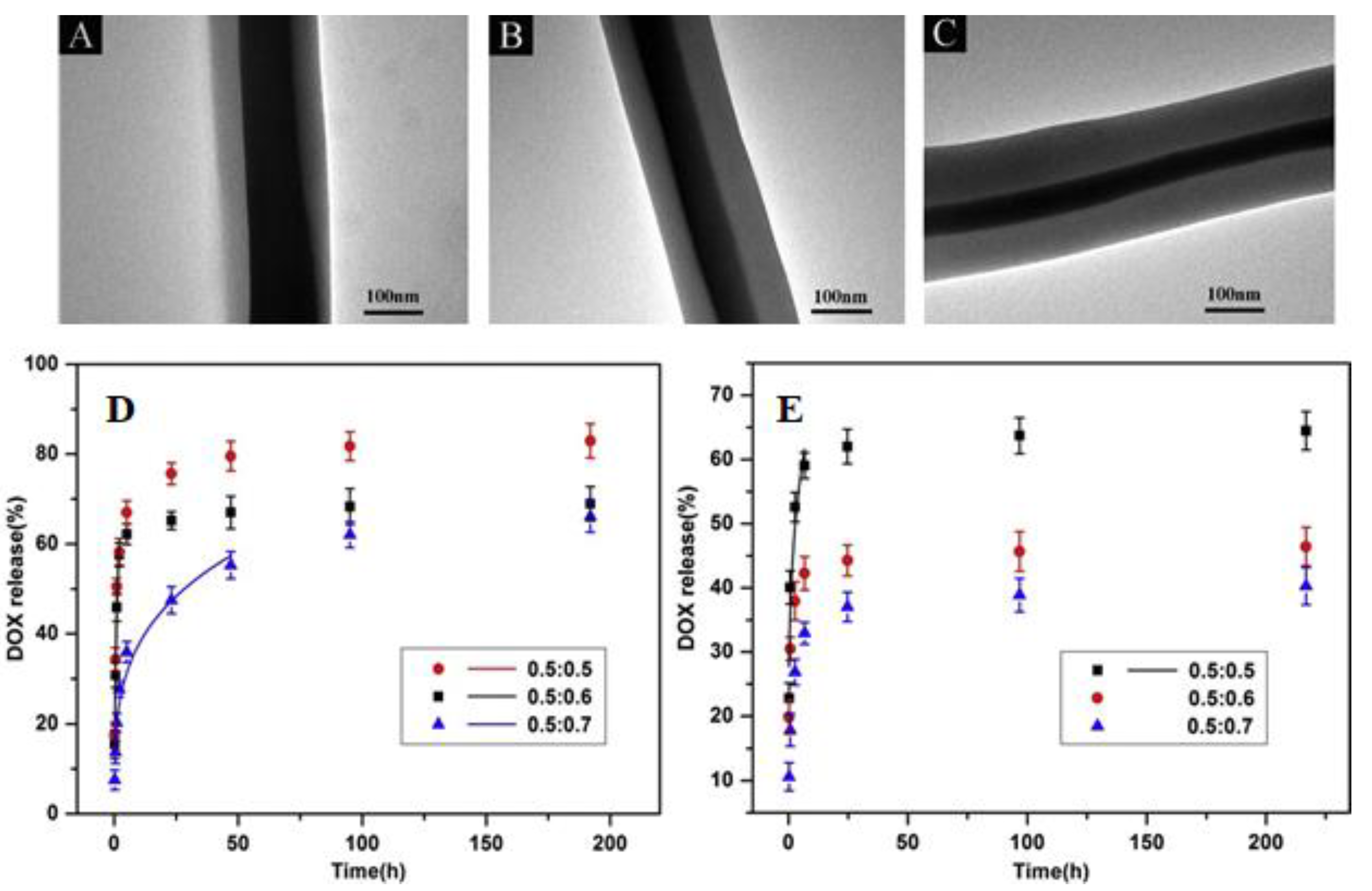
3.2. Coaxial Electrospinning
Applications of Coaxial Electrospinning in Drug Delivery
| Drug(s) | Core Fluid | Sheath Fluid | Solvent(s) | Drug Release Characteristics | Reference |
|---|---|---|---|---|---|
| Gentamicin | PCL and Pluronic ® F-127 | Silver and PCL | DCM and DMF | Initial burst followed by Sustained drug release | [108] |
| Silibinin | PEG-PLGA with Ag or Au | Fe2O3 in PVA | DCM | Sustained drug release | [109] |
| Doxorubicin | PVA | PCL | Distilled water and 2,2,2-Trifluoroethanol via stirring | pH-responsive drug release | [110] |
| Rosuvastatin | PCL | Chitosan | Acetic acid | pH-responsive release | [111] |
| Erythromycin | PCL | Zein with Titanium dioxide nanoparticles | Chloroform and ethanol | Sustained release | [112] |
| Moxifloxacin | PVP | PLGA | Acetonitrile and ethanol | Initial burst, then sustained drug release | [114] |
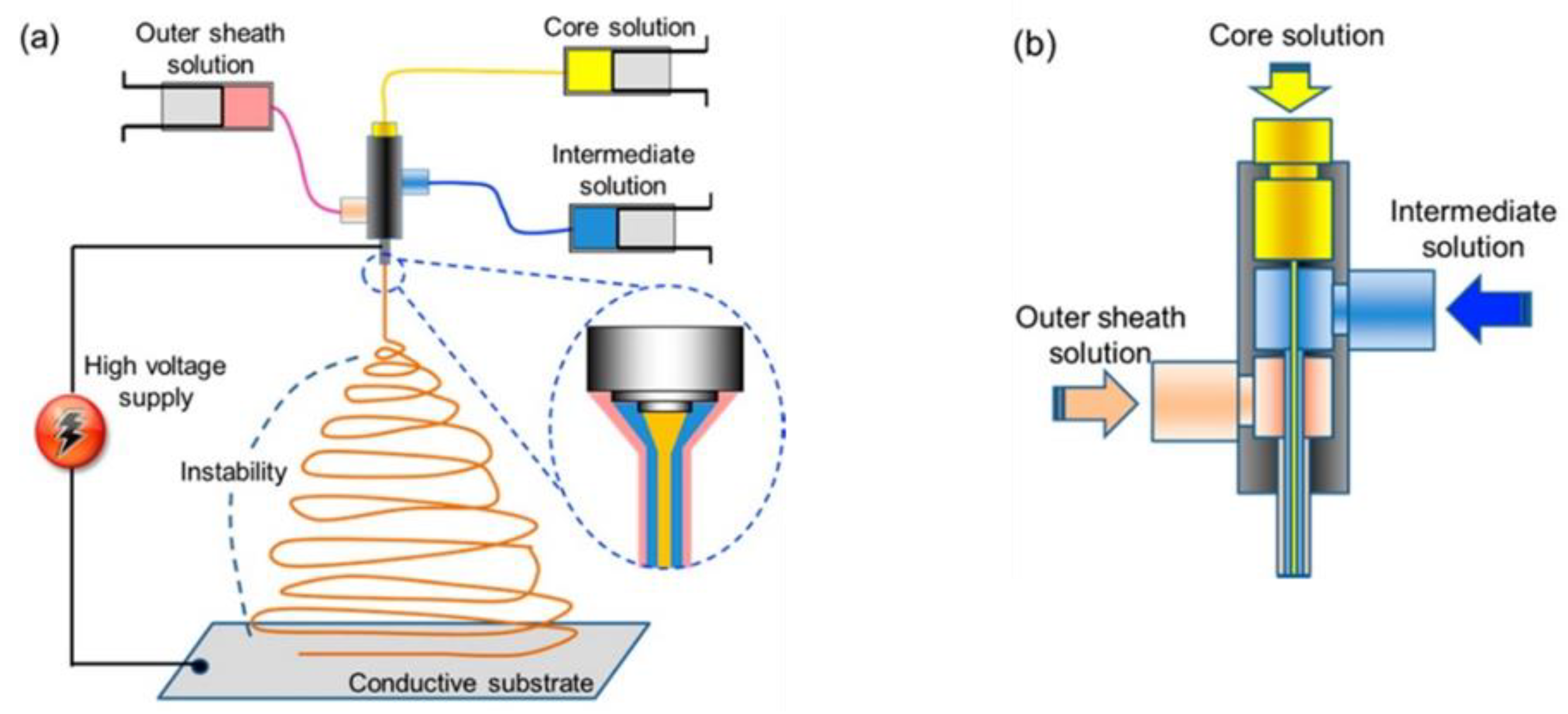
3.3. Triaxial Electrospinning
Applications of Triaxial Electrospinning in Drug Delivery
| Drug(s) | Core Layer | Intermediate Layer | Sheath Layer | Drug Release Characteristics | Reference |
|---|---|---|---|---|---|
| Lecithin and Diclofenac sodium | Lecithin and diclofenac sodium | Eudragit S100 | Ethanol | pH-controlled drug release | [123] |
| 5-fluorouracil, Doxorubicin and Paclitaxel | Chitosan/PVA | PLA/Chitosan | PLA/chitosan | Controlled drug release | [124] |
| Doxorubicin and apatinib | Glycerol | PLLA and PCL | Initial burst followed by sustained drug release | [125] | |
| Rhodamine B and Fluorescein isothiocyanate-Bovine Serum Albumin conjugate | PCL | Gelatin | PLGA | Dual drug release. | [126] |
| Aspirin | Eudragit (ES100) with Aspirin | Eudragit® S100 | Ethanol and DMAc | Extended drug release | [127] |
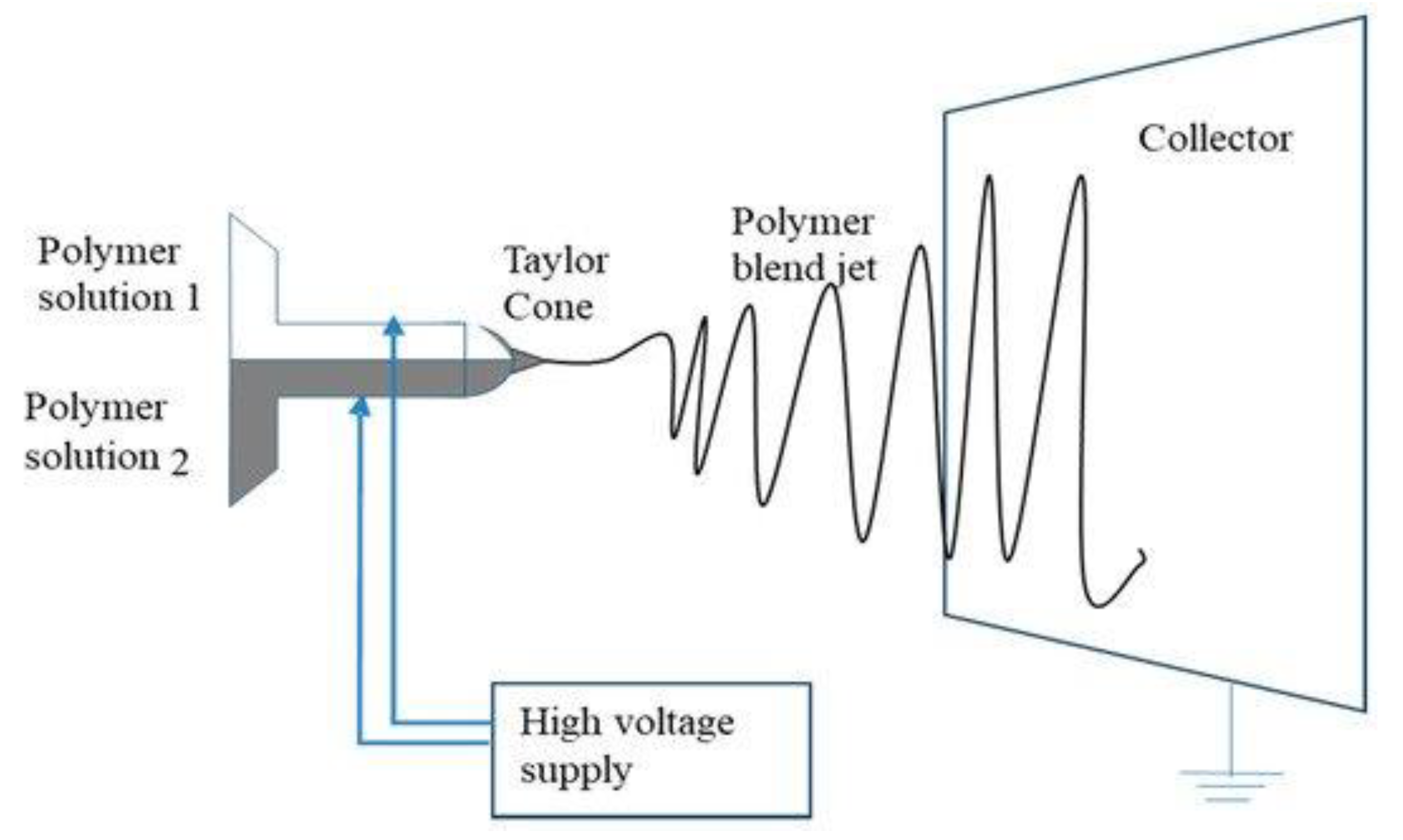
3.4. Side-by-Side Electrospinning
Applications of Side-by-Side Electrospinning in Drug Delivery
4. Centrifugal Spinning
4.1. Brief History of Centrifugal Spinning
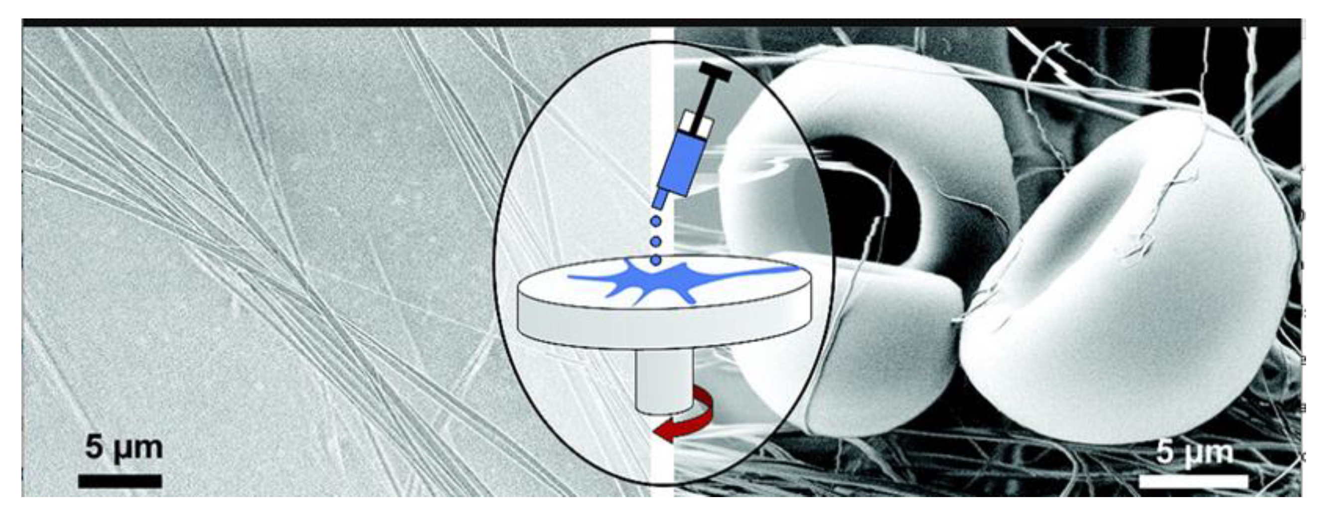
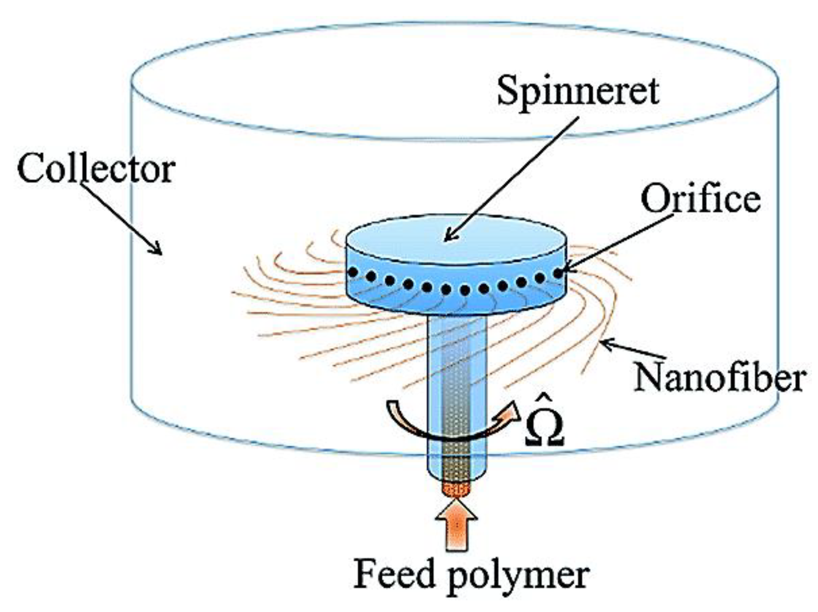
4.2. Basic Centrifugal Spinning Mechanism
4.3. Effect of Processing Parameters for Fibre Morphology and Diameter
4.4. Viscosity and Surface Tension of the Spinning Solution
4.5. Spinneret Speed
4.6. Collection Distance from the Spinneret
4.7. Diameter of the Orifice
4.8. Applications of Centrifugal Spinning in Drug Delivery
| Drug(s) | Polymer/Carrier | Solvent(s) | Drug Release Characteristics | Reference |
|---|---|---|---|---|
| Tetracycline | PVP/PCL | Chloroform/ethanol | Rapid drug release followed by sustained drug release | [133] |
| Carvedilol | Hydroxypropyl cellulose | Ethanol | Rapid drug release | [152] |
| Olanzapine and piroxicam | Sucrose | - | Fast disintegrating drug release | [153] |
| Ibuprofen, Indomethacin, tinidazole, nifedipine and metoprolol tartrate | Eudragit® EPO, Eudragit® RS Polyethylene glycol, Soluplus® | - | Modulable drug release | [154] |
| Tetracycline hydrogen chloride | PVP | Ethanol | Faster drug release followed by controlled drug release | [155] |
| Platelet | PCL | Chloroform and ethanol | Dose dependant drug release | [160] |
| Ibuprofen and Ketoprofen | PEO | Water/sodium hydroxide | Fast drug release without initial burst, then sustained drug release | [156] |
| Cinnamaldehyde or silver | Chitosan | Trifluoroacetic/dichloromethane | - | [157] |
| Ciprofloxacin | PLA/GE | HFP | Initial burst release of drug followed by sustained drug release | [158] |
| Bacterial cellulose | PLA/PCL | Chloroform | - | [159] |
| TGF-β, IGF and bFGF | PCL | Ethanol and chloroform | Prolonged drug release | [161] |
| Doxorubicin | PCL/PMPMA-CNOs | Trifluoroacetic acid | Sustained drug release | [162] |
5. Solution and Melt Blowing Spinning
5.1. Factors Affecting Solution Blowing and Melt Blowing Spinning
5.2. Applications of Solution- and Melt-Blowing in Drug Delivery
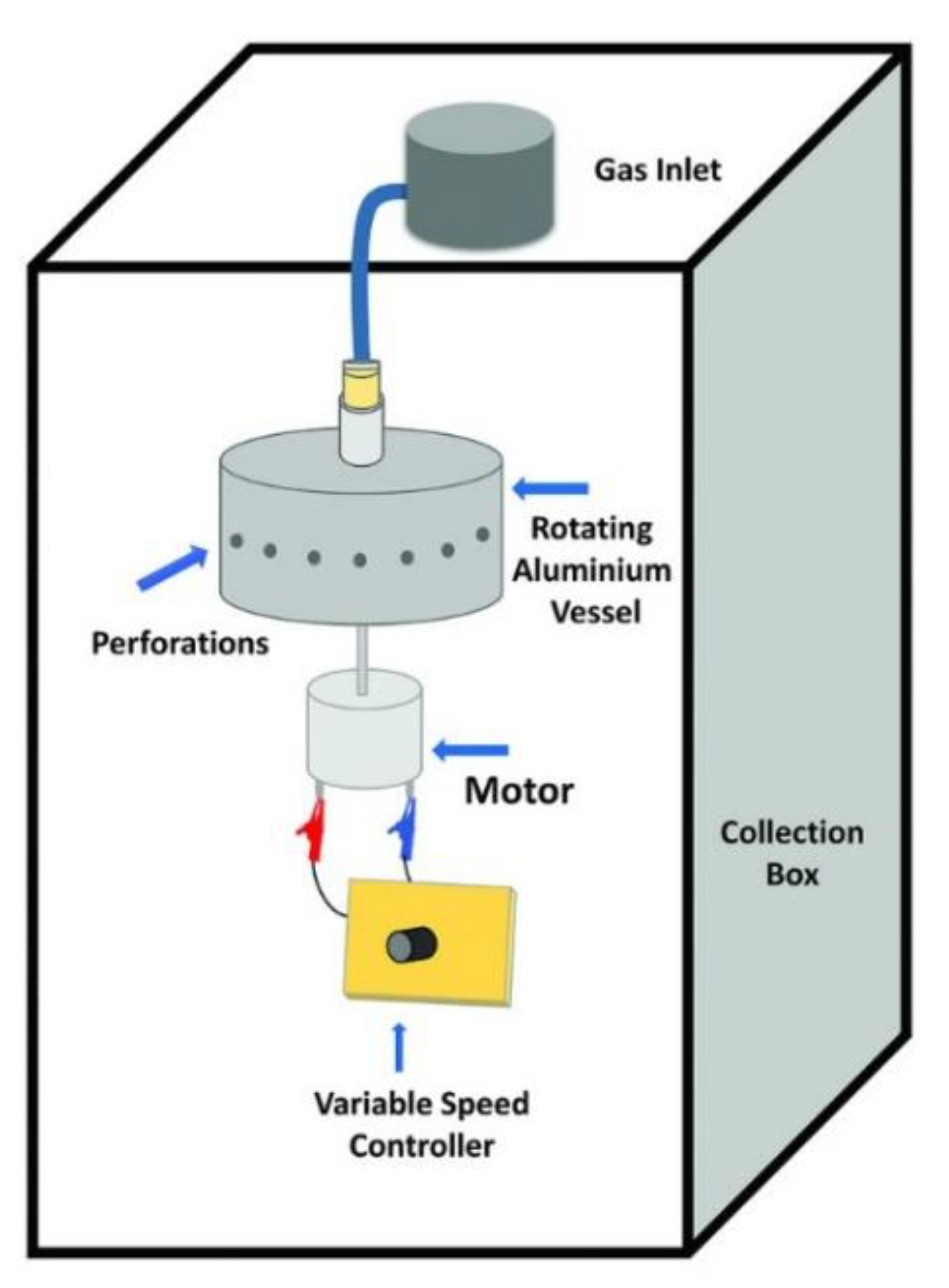
6. Pressurised Gyration
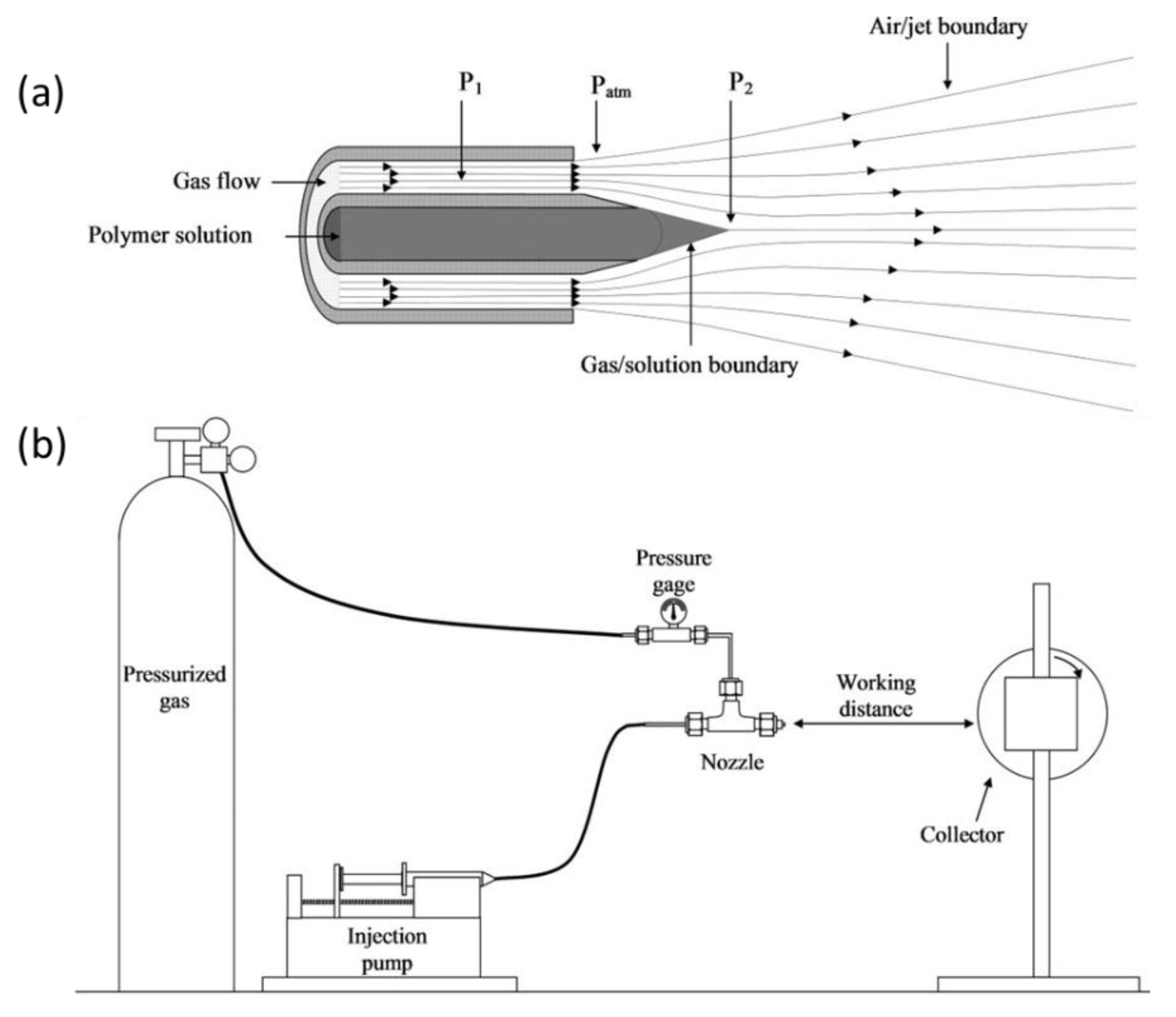
6.1. Mechanism of Pressurised Gyration
6.2. System Parameters of Pressurised Gyration
6.3. Applications of Pressurised Gyration in Drug Delivery
| Drug(s) | Polymer(s) | Solvent(s) | Drug Release Characteristics | Reference |
|---|---|---|---|---|
| Ibuprofen | PVP | Ethanol | Fast drug release | [174] |
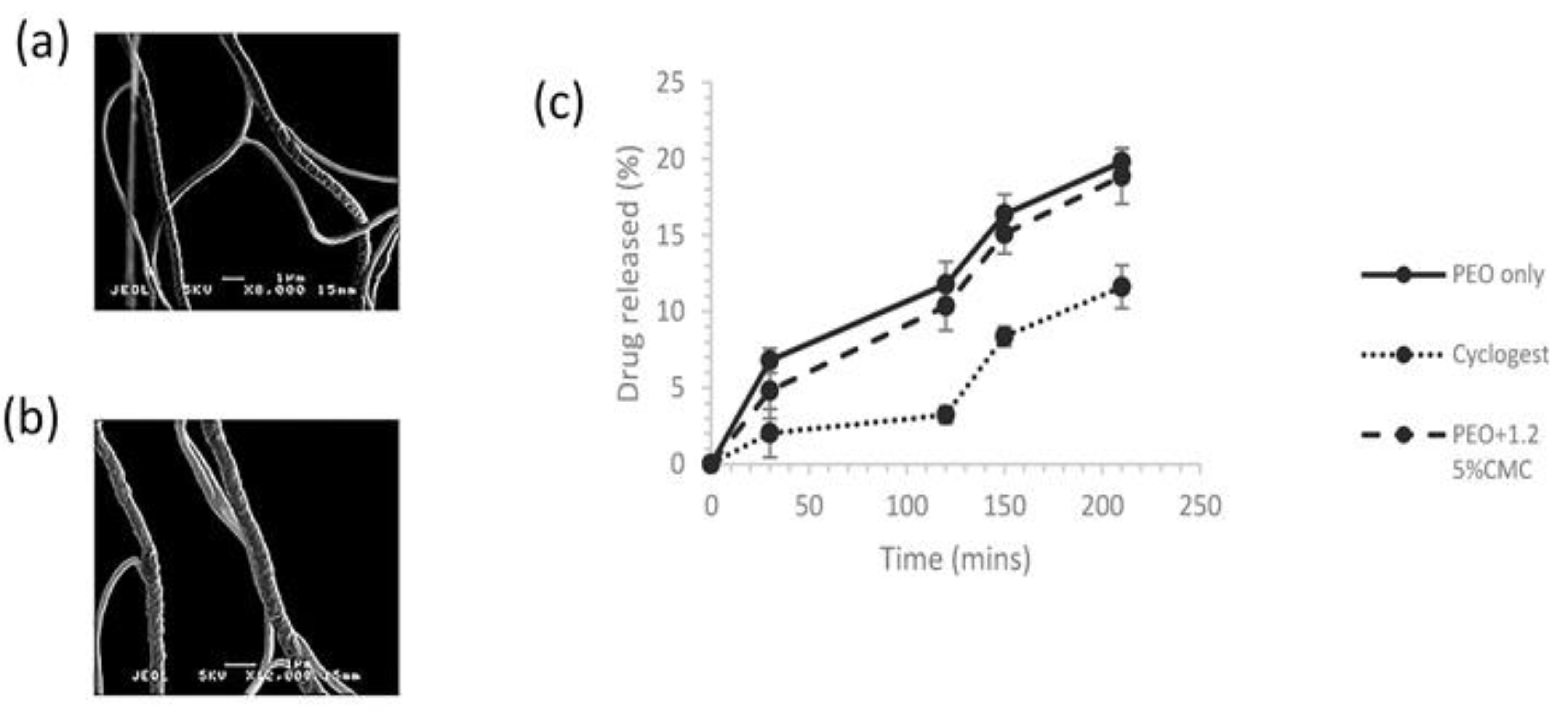
| Progesterone | PEO and CMC | Ethanol | Zero-order drug release | [175] |
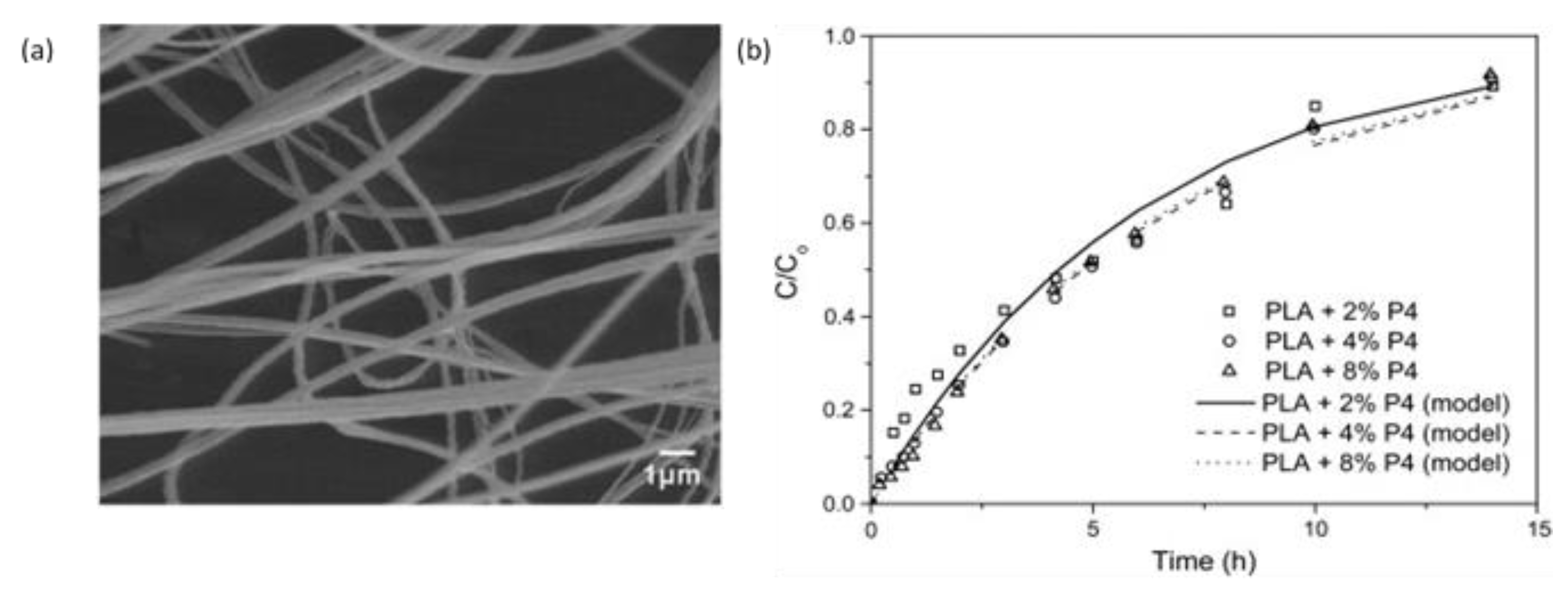
| Progesterone | PLA | Chloroform | Initial burst release followed by sustained drug release | [176] |
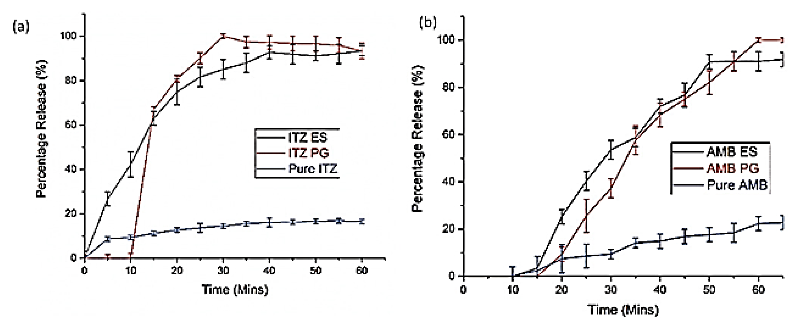
| Itraconazole and amphotericin B | PVP, PMMA, PNIPAM, and PVDF | Ethanol, dichloromethane, acetone, chloroform, dimethylformamide | Fast drug release | [177] |
| Cinnamon | PCL | Chloroform | - | [178] |
| Pioglitazone hydrochloride | PCL and PVP | Ethanol | Depends on the polymer concentration in the fibres. Some showed burst release, while one formulation showed sustained drug release | [179] |
| Pioglitazone Glibenclamide Metformin | PVP/PCL | Chloroform and methanol | Initial burst followed by sustained drug release | [180] |
7. Other Techniques
8. Conclusions
9. Challenges and Future Outlook
Author Contributions
Funding
Institutional Review Board Statement
Data Availability Statement
Acknowledgments
Conflicts of Interest
References
- Khan, S.; Mansoor, S.; Rafi, Z.; Kumari, B.; Shoaib, A.; Saeed, M.; Alshehri, S.; Ghoneim, M.M.; Rahamathulla, M.; Hani, U.; et al. A review on nanotechnology: Properties, applications, and mechanistic insights of cellular uptake mechanisms. J. Mol. Liq. 2022, 348, 118008. [Google Scholar] [CrossRef]
- Fajardo, C.; Martinez-Rodriguez, G.; Blasco, J.; Mancera, J.M.; Thomas, B.; De Donato, M. Nanotechnology in aquaculture: Applications, perspectives and regulatory challenges. Aquacult. Fish. 2022, 7, 185–200. [Google Scholar] [CrossRef]
- Singh, G.; Kapoor, I.; Dubey, S.; Siril, P.F. Preparation, characterization and catalytic activity of transition metal oxide nanocrystals. J. Sci. Conf. Proc. 2009, 1, 11–17. [Google Scholar] [CrossRef]
- Kumar, R.; Aadil, K.R.; Ranjan, S.; Kumar, V.B. Advances in nanotechnology and nanomaterials based strategies for neural tissue engineering. J. Drug Deliv. Sci. Technol. 2020, 57, 101617. [Google Scholar] [CrossRef]
- Sridhar, R.; Lakshminarayanan, R.; Madhaiyan, K.; Barathi, V.A.; Lim, K.H.C.; Ramakrishna, S. Electrosprayed nanoparticles and electrospun nanofibers based on natural materials: Applications in tissue regeneration, drug delivery and pharmaceuticals. Chem. Soc. Rev. 2015, 44, 790–814. [Google Scholar] [CrossRef] [PubMed] [Green Version]
- Shanmugam, V.; Selvakumar, S.; Yeh, C.-S. Near-infrared light-responsive nanomaterials in cancer therapeutics. Chem. Soc. Rev. 2014, 43, 6254–6287. [Google Scholar] [CrossRef] [Green Version]
- Mehta, P.; Zaman, A.; Smith, A.; Rasekh, M.; Haj-Ahmad, R.; Arshad, M.S.; van der Merwe, S.; Chang, M.-W.; Ahmad, Z. Broad Scale and Structure Fabrication of Healthcare Materials for Drug and Emerging Therapies via Electrohydrodynamic Techniques. Adv. Ther. 2019, 2, 1800024. [Google Scholar] [CrossRef] [Green Version]
- Ingavle, G.C.; Leach, J.K. Advancements in electrospinning of polymeric nanofibrous scaffolds for tissue engineering. Tissue Eng. B 2014, 20, 277–293. [Google Scholar] [CrossRef]
- Oliveira, J.E.; Mattoso, L.H.; Orts, W.J.; Medeiros, E.S. Structural and morphological characterization of micro and nanofibers produced by electrospinning and solution blow spinning: A comparative study. Adv. Mater. Sci. Eng. 2013, 2013, 409572. [Google Scholar] [CrossRef] [Green Version]
- Rezaei, A.; Nasirpour, A.; Fathi, M. Application of Cellulosic Nanofibers in Food Science Using Electrospinning and Its Potential Risk. Compr. Rev. Food Sci. Food Saf. 2015, 14, 269–284. [Google Scholar] [CrossRef]
- Kajdič, S.; Planinšek, O.; Gašperlin, M.; Kocbek, P. Electrospun nanofibers for customized drug-delivery systems. J. Drug Deliv. Sci. Technol. 2019, 51, 672–681. [Google Scholar] [CrossRef]
- Tan, E.P.S.; Lim, C.T. Mechanical characterization of nanofibers—A review. Compos. Sci. Technol. 2006, 66, 1102–1111. [Google Scholar] [CrossRef]
- Patel, G.C.; Yadav, B.K. Polymeric nanofibers for controlled drug delivery applications. In Organic Materials as Smart Nanocarriers for Drug Delivery; Patel, G.C., Yadav, B., Eds.; William Andrew Publishing: Norwich, NY, USA, 2018; pp. 147–175. [Google Scholar]
- Rahman, M.M. Introductory Chapter: Overview of Nanofibers. In Nanofiber Research Reaching New Heights; Rahman, M.M., Asiri, A., Eds.; IntechOpen: London, UK, 2016; pp. 3–8. [Google Scholar]
- Unnithan, A.R.; Barakat, N.A.M.; Pichiah, P.B.T.; Gnanasekaran, G.; Nirmala, R.; Cha, Y.-S.; Jung, C.-H.; Newehy, M.E.-N.; Kim, H.Y. Wound-dressing materials with antibacterial activity from electrospun polyurethane–dextran nanofiber mats containing ciprofloxacin HCl. Carbohydr. Polym. 2012, 90, 1786–1793. [Google Scholar] [CrossRef] [PubMed]
- Faccini, M.; Vaquero, C.; Amantia, D. Development of protective clothing against nanoparticle based on electrospun nanofibers. J. Nanomater. 2012, 2012, 892894. [Google Scholar] [CrossRef] [Green Version]
- Sundarrajan, S.; Tan, K.L.; Lim, S.H.; Ramakrishna, S. Electrospun nanofibers for air filtration applications. Procedia Eng. 2014, 75, 159–163. [Google Scholar] [CrossRef] [Green Version]
- Hrib, J.; Sirc, J.; Hobzova, R.; Hampejsova, Z.; Bosakova, Z.; Munzarova, M.; Michalek, J. Nanofibers for drug delivery—Incorporation and release of model molecules, influence of molecular weight and polymer structure. Beilstein J. Nanotechnol. 2015, 6, 1939–1945. [Google Scholar] [CrossRef] [Green Version]
- Zahmatkeshan, M.; Adel, M.; Bahrami, S.; Esmaeili, F.; Rezayat, S.M.; Saeedi, Y.; Mehravi, B.; Ashtari, K. Polymer Based Nanofibers: Preparation, Fabrication, and Applications. In Handbook of Nanofibers; Barhoum, A., Bechelany, M., Makhlouf, A., Eds.; Springer International Publishing: Cham, Switzerland, 2018; pp. 1–47. [Google Scholar]
- Abdul Hameed, M.M.; Mohamed Khan, S.A.P.; Thamer, B.M.; Rajkumar, N.; El-Hamshary, H.; El-Newehy, M. Electrospun nanofibers for drug delivery applications: Methods and mechanism. Polym. Adv. Technol. 2023, 34, 6–23. [Google Scholar] [CrossRef]
- Sill, T.J.; Von Recum, H.A. Electrospinning: Applications in drug delivery and tissue engineering. Biomaterials 2008, 29, 1989–2006. [Google Scholar] [CrossRef]
- Reneker, D.H.; Yarin, A.L. Electrospinning jets and polymer nanofibers. Polymer 2008, 49, 2387–2425. [Google Scholar] [CrossRef] [Green Version]
- Baji, A.; Mai, Y.-W.; Wong, S.-C.; Abtahi, M.; Chen, P. Electrospinning of polymer nanofibers: Effects on oriented morphology, structures and tensile properties. Compos. Sci. Technol. 2010, 70, 703–718. [Google Scholar] [CrossRef]
- Mottaghitalab, V.; Haghi, A.K. A study on electrospinning of polyacrylonitrile nanofibers. Korean J. Chem. Eng. 2011, 28, 114–118. [Google Scholar] [CrossRef]
- Lu, H.; Chen, W.-J.; Xing, Y.; Ying, D.-J.; Jiang, B. Design and preparation of an electrospun biomaterial surgical patch. J. Bioact. Compat. Polym. 2009, 24, 158–168. [Google Scholar] [CrossRef]
- Nisbet, D.R.; Forsythe, J.S.; Shen, W.; Finkelstein, D.I.; Horne, M.K. A review of the cellular response on electrospun nanofibers for tissue engineering. J. Biomater. Appl. 2009, 24, 7–29. [Google Scholar] [CrossRef] [PubMed]
- Bhattarai, S.R.; Bhattarai, N.; Yi, H.K.; Hwang, P.H.; Cha, D.I.; Kim, H.Y. Novel biodegradable electrospun membrane: Scaffold for tissue engineering. Biomaterials 2004, 25, 2595–2602. [Google Scholar] [CrossRef]
- Li, W.J.; Laurencin, C.T.; Caterson, E.J.; Tuan, R.S.; Ko, F.K. Electrospun nanofibrous structure: A novel scaffold for tissue engineering. J. Biomed. Mater. Res. 2002, 60, 613–621. [Google Scholar] [CrossRef]
- Lee, S.; Obendorf, S.K. Use of electrospun nanofiber web for protective textile materials as barriers to liquid penetration. Text. Res. J. 2007, 77, 696–702. [Google Scholar] [CrossRef]
- Thavasi, V.; Singh, G.; Ramakrishna, S. Electrospun nanofibers in energy and environmental applications. Energy Environ. Sci. 2008, 1, 205–221. [Google Scholar] [CrossRef]
- Tucker, N.; Stanger, J.J.; Staiger, M.P.; Razzaq, H.; Hofman, K. The history of the science and technology of electrospinning from 1600 to 1995. J. Eng. Fibers Fabr. 2012, 7 (Suppl. 2), 63–73. [Google Scholar] [CrossRef] [Green Version]
- Anton, F. Process and Apparatus for Preparing Artificial Threads. U.S. Patent US1975504A, 2 October 1934. [Google Scholar]
- Formhals, A. Method and Apparatus for Spinning. U.S. Patent 2,349,950, 2 October 1934. [Google Scholar]
- Taylor, G.I. Disintegration of water drops in an electric field. Proc. R. Soc. Lond. A 1964, 280, 383–397. [Google Scholar]
- Taylor, G.I. Electrically driven jets. Proc. R. Soc. Lond. A 1969, 313, 453–475. [Google Scholar]
- Doshi, J.; Reneker, D.H. Electrospinning process and applications of electrospun fibers. J. Electrostat. 1995, 35, 151–160. [Google Scholar] [CrossRef]
- Kowalewski, T.; Hiller, W.; Behnia, M. An experimental study of evaporating small diameter jets. Phys. Fluid A 1993, 5, 1883–1890. [Google Scholar] [CrossRef] [Green Version]
- Vass, P.; Szabó, E.; Domokos, A.; Hirsch, E.; Galata, D.; Farkas, B.; Démuth, B.; Andersen, S.K.; Vigh, T.; Verreck, G.; et al. Scale-up of electrospinning technology: Applications in the pharmaceutical industry. Wiley Interdiscip. Rev. Nanomed. Nanobiotechnol. 2020, 12, e1611. [Google Scholar] [CrossRef] [Green Version]
- Sahay, R.; Thavasi, V.; Ramakrishna, S. Design Modifications in Electrospinning Setup for Advanced Applications. J. Nanomater. 2011, 2011, 317673. [Google Scholar] [CrossRef] [Green Version]
- He, X.-X.; Zheng, J.; Yu, G.-F.; You, M.-H.; Yu, M.; Ning, X.; Long, Y.Z. Near-field electrospinning: Progress and applications. J. Phys. Chem. C 2017, 121, 8663–8678. [Google Scholar] [CrossRef]
- Kriegel, C.; Arecchi, A.; Kit, K.; McClements, D.J.; Weiss, J. Fabrication, functionalization, and application of electrospun biopolymer nanofibers. Crit. Rev. Food Sci. Nutr. 2008, 48, 775–797. [Google Scholar] [CrossRef]
- Haider, A.; Haider, S.; Kang, I.-K. A comprehensive review summarizing the effect of electrospinning parameters and potential applications of nanofibers in biomedical and biotechnology. Arab. J. Chem. 2018, 11, 1165–1188. [Google Scholar] [CrossRef]
- Ribeiro, C.; Sencadas, V.; Ribelles, J.L.G.; Lanceros-Méndez, S. Influence of processing conditions on polymorphism and nanofiber morphology of electroactive poly (vinylidene fluoride) electrospun membranes. Soft Mater. 2010, 8, 274–287. [Google Scholar] [CrossRef]
- Beachley, V.; Wen, X. Effect of electrospinning parameters on the nanofiber diameter and length. Mater. Sci. Eng. C 2009, 29, 663–668. [Google Scholar] [CrossRef] [Green Version]
- Fridrikh, S.V.; Jian, H.Y.; Brenner, M.P.; Rutledge, G.C. Controlling the fiber diameter during electrospinning. Phys. Rev. Lett. 2003, 90, 144502. [Google Scholar] [CrossRef] [Green Version]
- Megelski, S.; Stephens, J.S.; Chase, D.B.; Rabolt, J.F. Micro-and nanostructured surface morphology on electrospun polymer fibers. Macromolecules 2002, 35, 8456–8466. [Google Scholar] [CrossRef]
- Gu, S.; Ren, J.; Vancso, G. Process optimization and empirical modeling for electrospun polyacrylonitrile (PAN) nanofiber precursor of carbon nanofibers. Eur. Polym. J. 2005, 41, 2559–2568. [Google Scholar] [CrossRef]
- Tan, S.-H.; Inai, R.; Kotaki, M.; Ramakrishna, S. Systematic parameter study for ultra-fine fiber fabrication via electrospinning process. Polymer 2005, 46, 6128–6134. [Google Scholar] [CrossRef]
- Deitzel, J.M.; Kleinmeyer, J.; Harris, D.; Tan, N.B. The effect of processing variables on the morphology of electrospun nanofibers and textiles. Polymer 2001, 42, 261–272. [Google Scholar] [CrossRef]
- Tang, X.-P.; Si, N.; Xu, L.; Liu, H.-Y. Effect of flow rate on diameter of electrospun nanoporous fibers. Therm. Sci. 2014, 18, 1447–1449. [Google Scholar] [CrossRef]
- Barua, B.; Saha, M.C. Investigation on jet stability, fiber diameter, and tensile properties of electrospun polyacrylonitrile nanofibrous yarns. J. Appl. Polym. Sci. 2015, 132, 18. [Google Scholar] [CrossRef]
- Matabola, K.P.; Moutloali, R.M. The influence of electrospinning parameters on the morphology and diameter of poly(vinyledene fluoride) nanofibers-effect of sodium chloride. J. Mater. Sci. 2013, 48, 5475–5482. [Google Scholar] [CrossRef]
- Bhardwaj, N.; Kundu, S.C. Electrospinning: A fascinating fiber fabrication technique. Biotechnol. Adv. 2010, 28, 325–347. [Google Scholar]
- Wang, T.; Kumar, S. Electrospinning of polyacrylonitrile nanofibers. J. Appl. Polym. Sci. 2006, 102, 1023–1029. [Google Scholar] [CrossRef]
- Zhang, C.; Yuan, X.; Wu, L.; Han, Y.; Sheng, J. Study on morphology of electrospun poly(vinyl alcohol) mats. Eur. Polym. J. 2005, 41, 423–432. [Google Scholar] [CrossRef]
- M.Moghadam, S.; Dong, Y.; Barbhuiya, S.; Guo, L.; Liu, D.; Umer, R.; Qi, X.; Tang, Y. Electrospinning: Current Status and Future Trends. In Nano-Size Polymers; Fakirov, S., Ed.; Springer: Cham, Switzerland, 2016; pp. 89–154. [Google Scholar]
- Jiang, S.; Lv, L.-P.; Landfester, K.; Crespy, D. Nanocontainers in and onto Nanofibers. Acc. Chem. Res. 2016, 49, 816–823. [Google Scholar] [CrossRef] [PubMed]
- Balaji, A.; Vellayappan, M.; John, A.; Subramanian, A.; Jaganathan, S.; Supriyanto, E.; Razak, S.I.A. An insight on electrospun-nanofibers-inspired modern drug delivery system in the treatment of deadly cancers. RSC Adv. 2015, 5, 57984–58004. [Google Scholar] [CrossRef]
- Zong, X.; Kim, K.; Fang, D.; Ran, S.; Hsiao, B.S.; Chu, B. Structure and process relationship of electrospun bioabsorbable nanofiber membranes. Polymer 2002, 43, 4403–4412. [Google Scholar] [CrossRef]
- Liu, G.; Gu, Z.; Hong, Y.; Cheng, L.; Li, C. Electrospun starch nanofibers: Recent advances, challenges, and strategies for potential pharmaceutical applications. J. Control. Release 2017, 252, 95–107. [Google Scholar] [CrossRef] [PubMed]
- Son, W.K.; Youk, J.H.; Park, W.H. Preparation of Ultrafine Oxidized Cellulose Mats via Electrospinning. Biomacromolecules 2004, 5, 197–201. [Google Scholar] [CrossRef]
- Son, W.K.; Youk, J.H.; Lee, T.S.; Park, W.H. Preparation of Antimicrobial Ultrafine Cellulose Acetate Fibers with Silver Nanoparticles. Macromol. Rapid Commun. 2004, 25, 1632–1637. [Google Scholar] [CrossRef]
- Mit-uppatham, C.; Nithitanakul, M.; Supaphol, P. Ultrafine Electrospun Polyamide-6 Fibers: Effect of Solution Conditions on Morphology and Average Fiber Diameter. Macromol. Chem. Phys. 2004, 205, 2327–2338. [Google Scholar] [CrossRef]
- Fashandi, H.; Karimi, M. Pore formation in polystyrene fiber by superimposing temperature and relative humidity of electrospinning atmosphere. Polymer 2012, 53, 5832–5849. [Google Scholar] [CrossRef]
- Gifford-Hollingsworth, R.C. Varying the Porosity of Electrospun Monoaxial and Coaxial Collagen Nanofibers. Master’s Thesis, Drexel University, Philadelphia, PA, USA, 2014. [Google Scholar]
- Rafiei, S.; Maghsoodloo, S.; Saberi, M.; Lotfi, S.; Motaghitalab, V.; Noroozi, B.; Haghi, A.K. New horizons in modeling and simulation of electrospun nanofibers: A detailed review. Cellul. Chem. Technol. 2014, 48, 401–424. [Google Scholar]
- Ball, C.; Krogstad, E.; Chaowanachan, T.; Woodrow, K.A. Drug-eluting fibers for HIV-1 inhibition and contraception. PLoS ONE 2012, 7, e49792. [Google Scholar] [CrossRef]
- Blakney, A.K.; Ball, C.; Krogstad, E.A.; Woodrow, K.A. Electrospun fibers for vaginal anti-HIV drug delivery. Antivir. Res. 2013, 100, S9–S16. [Google Scholar] [CrossRef] [PubMed]
- Zupančič, Š.; Sinha-Ray, S.; Sinha-Ray, S.; Kristl, J.; Yarin, A.L. Long-term sustained ciprofloxacin release from pmma and hydrophilic polymer blended nanofibers. Mol. Pharm. 2016, 13, 295–305. [Google Scholar] [CrossRef]
- Chou, S.-F.; Carson, D.; Woodrow, K.A. Current strategies for sustaining drug release from electrospun nanofibers. J. Control. Release 2015, 220, 584–591. [Google Scholar] [CrossRef] [PubMed] [Green Version]
- Krogstad, E.A.; Woodrow, K.A. Manufacturing scale-up of electrospun poly(vinyl alcohol) fibers containing tenofovir for vaginal drug delivery. Int. J. Pharm. 2014, 475, 282–291. [Google Scholar] [CrossRef] [PubMed] [Green Version]
- Ball, C.; Woodrow, K.A. Electrospun solid dispersions of maraviroc for rapid intravaginal preexposure prophylaxis of HIV. Antimicrob. Agents Chemother. 2014, 58, 4855–4865. [Google Scholar] [CrossRef] [PubMed] [Green Version]
- Krogstad, E.A.; Rathbone, M.J.; Woodrow, K.A. Vaginal drug delivery. In Focal Controlled Drug Delivery; Domb, A., Khan, W., Eds.; Springer: Boston, MA, USA, 2014; pp. 607–651. [Google Scholar]
- Pisani, S.; Dorati, R.; Chiesa, E.; Genta, I.; Modena, T.; Bruni, G.; Grisoli, P.; Conti, B. Release Profile of Gentamicin Sulfate from Polylactide-co-Polycaprolactone Electrospun Nanofiber Matrices. Pharmaceutics 2019, 11, 161. [Google Scholar] [CrossRef] [Green Version]
- Behbood, L.; Moradipour, P.; Moradi, F.; Arkan, E. Mucoadhesive electrospun nanofibers of chitosan/gelatin containing vancomycin as a delivery system. J. Rep. Pharm. Sci. 2017, 6, 150. [Google Scholar]
- Li, Z.; Zeng, R.; Yang, L.; Ren, X.; Maffucci, K.G.; Qu, Y. Development and characterization of PCL electrospun membrane-coated Bletilla striata polysaccharide-based gastroretentive drug delivery system. AAPS PharmSciTech 2020, 21, 66. [Google Scholar] [CrossRef]
- Kuang, G.; Zhang, Z.; Liu, S.; Zhou, D.; Lu, X.; Jing, X.; Huang, Y. Biphasic drug release from electrospun polyblend nanofibers for optimized local cancer treatment. Biomater. Sci. 2018, 6, 324–331. [Google Scholar] [CrossRef] [Green Version]
- Hadjianfar, M.; Semnani, D.; Varshosaz, J. Polycaprolactone/chitosan blend nanofibers loaded by 5-fluorouracil: An approach to anticancer drug delivery system. Polym. Adv. Technol. 2018, 29, 2972–2981. [Google Scholar] [CrossRef]
- Zhao, J.; Cui, W. Fabrication of acid-responsive electrospun fibers via doping sodium bicarbonate for quick releasing drug. Nanosci. Nanotechnol. Lett. 2014, 6, 339–345. [Google Scholar] [CrossRef]
- Kersani, D.; Mougin, J.; Lopez, M.; Degoutin, S.; Tabary, N.; Cazaux, F.; Janus, L.; Maton, M.; Chai, F.; Sobocinski, J. Stent coating by electrospinning with chitosan/poly-cyclodextrin based nanofibers loaded with simvastatin for restenosis prevention. Eur. J. Pharm. Biopharm. 2020, 150, 156–167. [Google Scholar] [CrossRef] [PubMed]
- Bakola, V.; Karagkiozaki, V.; Tsiapla, A.; Pappa, F.; Moutsios, I.; Pavlidou, E.; Logothetidis, S. Dipyridamole-loaded biodegradable PLA nanoplatforms as coatings for cardiovascular stents. Nanotechnology 2018, 29, 275101. [Google Scholar] [CrossRef] [PubMed] [Green Version]
- Mehta, P.; Al-Kinani, A.A.; Arshad, M.S.; Chang, M.-W.; Alany, R.G.; Ahmad, Z. Development and characterisation of electrospun timolol maleate-loaded polymeric contact lens coatings containing various permeation enhancers. Int. J. Pharm. 2017, 532, 408–420. [Google Scholar] [CrossRef] [Green Version]
- Grimaudo, M.A.; Concheiro, A.; Alvarez-Lorenzo, C. Crosslinked Hyaluronan Electrospun Nanofibers for Ferulic Acid Ocular Delivery. Pharmaceutics 2020, 12, 274. [Google Scholar] [CrossRef] [PubMed] [Green Version]
- Akhgari, A.; Heshmati, Z.; Afrasiabi Garekani, H.; Sadeghi, F.; Sabbagh, A.; Sharif Makhmalzadeh, B.; Nokhodchi, A. Indomethacin electrospun nanofibers for colonic drug delivery: In vitro dissolution studies. Colloids Surf. B 2017, 152, 29–35. [Google Scholar] [CrossRef] [Green Version]
- Chen, Z.; Chen, Z.; Zhang, A.; Hu, J.; Wang, X.; Yang, Z. Electrospun nanofibers for cancer diagnosis and therapy. Biomater. Sci. 2016, 4, 922–932. [Google Scholar] [CrossRef]
- Jouybari, M.H.; Hosseini, S.; Mahboobnia, K.; Boloursaz, L.A.; Moradi, M.; Irani, M. Simultaneous controlled release of 5-FU, DOX and PTX from chitosan/PLA/5-FU/g-C3N4-DOX/g-C3N4-PTX triaxial nanofibers for breast cancer treatment in vitro. Colloids Surf. B 2019, 179, 495–504. [Google Scholar] [CrossRef]
- Anothra, P.; Pradhan, D.; Naik, P.K.; Ghosh, G.; Rath, G. Development and characterization of 5-fluorouracil nanofibrous film for the treatment of stomach cancer. J. Drug Deliv. Sci. Technol. 2021, 61, 102219. [Google Scholar] [CrossRef]
- Esfahani, R.E.; Zahedi, P.; Zarghami, R. 5-Fluorouracil-loaded poly(vinyl alcohol)/chitosan blend nanofibers: Morphology, drug release and cell culture studies. Iran. Polym. J. 2021, 30, 167–177. [Google Scholar] [CrossRef]
- Ghahreman, F.; Semnani, D.; Khorasani, S.N.; Varshosaz, J.; Khalili, S.; Mohammadi, S.; Kaviannasab, E. Polycaprolactone–Gelatin Membranes in Controlled Drug Delivery of 5-Fluorouracil. Polym. Sci. Ser. A 2020, 62, 636–647. [Google Scholar] [CrossRef]
- Hu, X.; Liu, S.; Zhou, G.; Huang, Y.; Xie, Z.; Jing, X. Electrospinning of polymeric nanofibers for drug delivery applications. J. Control. Release 2014, 185, 12–21. [Google Scholar] [CrossRef]
- Son, Y.J.; Kim, W.J.; Yoo, H.S. Therapeutic applications of electrospun nanofibers for drug delivery systems. Arch. Pharm. Res. 2014, 37, 69–78. [Google Scholar] [CrossRef]
- Aggarwal, U.; Goyal, A.K.; Rath, G. Development and characterization of the cisplatin loaded nanofibers for the treatment of cervical cancer. Mater. Sci. Eng. C 2017, 75, 125–132. [Google Scholar] [CrossRef]
- Kaplan, J.A.; Liu, R.; Freedman, J.D.; Padera, R.; Schwartz, J.; Colson, Y.L.; Grinstaff, M.W. Prevention of lung cancer recurrence using cisplatin-loaded superhydrophobic nanofiber meshes. Biomaterials 2016, 76, 273–281. [Google Scholar] [CrossRef] [Green Version]
- Absar, S.; Khan, M.; Edwards, K.; Calamas, D. Electrospinning of cisplatin-loaded cellulose nanofibers for cancer drug delivery. In Proceedings of the ASME 2014 International Mechanical Engineering Congress and Exposition, Montreal, QC, Canada, 14–20 November 2014; p. V009T012A085. [Google Scholar]
- Li, B.; Xia, X.; Chen, J.; Xia, D.; Xu, R.; Zou, X.; Wang, H.; Liang, C. Paclitaxel-loaded lignin particle encapsulated into electrospun PVA/PVP composite nanofiber for effective cervical cancer cell inhibition. Nanotechnology 2020, 32, 015101. [Google Scholar] [CrossRef]
- Chi, H.Y.; Chan, V.; Li, C.; Hsieh, J.H.; Lin, P.H.; Tsai, Y.-H.; Chen, Y. Fabrication of polylactic acid/paclitaxel nano fibers by electrospinning for cancer therapeutics. BMC Chem. 2020, 14, 63. [Google Scholar] [CrossRef]
- Samadzadeh, S.; Mousazadeh, H.; Ghareghomi, S.; Dadashpour, M.; Babazadeh, M.; Zarghami, N. In vitro anticancer efficacy of Metformin-loaded PLGA nanofibers towards the post-surgical therapy of lung cancer. J. Drug Deliv. Sci. Technol. 2021, 61, 102318. [Google Scholar] [CrossRef]
- Croitoru, A.-M.; Ficai, D.; Ficai, A.; Mihailescu, N.; Andronescu, E.; Turculet, C.F. Nanostructured Fibers Containing Natural or Synthetic Bioactive Compounds in Wound Dressing Applications. Materials 2020, 13, 2407. [Google Scholar] [CrossRef] [PubMed]
- Alavarse, A.C.; de Oliveira Silva, F.W.; Colque, J.T.; da Silva, V.M.; Prieto, T.; Venancio, E.C.; Bonvent, J.-J. Tetracycline hydrochloride-loaded electrospun nanofibers mats based on PVA and chitosan for wound dressing. Mater. Sci. Eng. C 2017, 77, 271–281. [Google Scholar] [CrossRef]
- Bakhsheshi-Rad, H.R.; Hadisi, Z.; Ismail, A.F.; Aziz, M.; Akbari, M.; Berto, F.; Chen, X.B. In vitro and in vivo evaluation of chitosan-alginate/gentamicin wound dressing nanofibrous with high antibacterial performance. Polym. Test. 2020, 82, 106298. [Google Scholar] [CrossRef]
- Hameed, M.; Rasul, A.; Nazir, A.; Yousaf, A.M.; Hussain, T.; Khan, I.U.; Abbas, G.; Abid, S.; Yousafi, Q.u.A.; Ghori, M.U. Moxifloxacin-loaded electrospun polymeric composite nanofibers-based wound dressing for enhanced antibacterial activity and healing efficacy. Int. J. Polym. Mater. Polym. Biomater. 2020, 70, 1271–1279. [Google Scholar] [CrossRef]
- Li, H.; Williams, G.R.; Wu, J.; Wang, H.; Sun, X.; Zhu, L.-M. Poly(N-isopropylacrylamide)/poly(l-lactic acid-co-ε-caprolactone) fibers loaded with ciprofloxacin as wound dressing materials. Mater. Sci. Eng. C 2017, 79, 245–254. [Google Scholar] [CrossRef]
- Chen, R.; Huang, C.; Ke, Q.; He, C.; Wang, H.; Mo, X. Preparation and characterization of coaxial electrospun thermoplastic polyurethane/collagen compound nanofibers for tissue engineering applications. Colloids Surf. B 2010, 79, 315–325. [Google Scholar] [CrossRef]
- Sun, Z.; Zussman, E.; Yarin, A.L.; Wendorff, J.H.; Greiner, A. Compound Core–Shell Polymer Nanofibers by Co-Electrospinning. Adv. Mater. 2003, 15, 1929–1932. [Google Scholar] [CrossRef]
- Vasita, R.; Gelain, F. Core-sheath fibers for regenerative medicine. In Nanomaterials in Drug Delivery, Imaging, and Tissue Engineering; John Wiley and Sons: Hoboken, NJ, USA, 2013; pp. 493–533. [Google Scholar]
- Lu, Y.; Huang, J.; Yu, G.; Cardenas, R.; Wei, S.; Wujcik, E.K.; Guo, Z. Coaxial electrospun fibers: Applications in drug delivery and tissue engineering. Wiley Interdiscip. Rev. Nanomed. Nanobiotechnol. 2016, 8, 654–677. [Google Scholar] [CrossRef]
- Tong, H.-W.; Zhang, X.; Wang, M. A new nanofiber fabrication technique based on coaxial electrospinning. Mater. Lett. 2012, 66, 257–260. [Google Scholar] [CrossRef]
- Chen, S.; Ge, L.; Mueller, A.; Carlson, M.A.; Teusink, M.J.; Shuler, F.D.; Xie, J. Twisting electrospun nanofiber fine strips into functional sutures for sustained co-delivery of gentamicin and silver. Nanomedicine 2017, 13, 1435–1445. [Google Scholar] [CrossRef] [Green Version]
- Fazio, E.; Ridolfo, A.; Neri, G. Thermally activated noble metal Nanoparticles incorporated in electrospun fiber-based drug delivery systems. Curr. Nanomater. 2019, 4, 21–31. [Google Scholar] [CrossRef]
- Yan, E.; Jiang, J.; Yang, X.; Fan, L.; Wang, Y.; An, Q.; Zhang, Z.; Lu, B.; Wang, D.; Zhang, D. pH-sensitive core-shell electrospun nanofibers based on polyvinyl alcohol/polycaprolactone as a potential drug delivery system for the chemotherapy against cervical cancer. J. Drug Deliv. Sci. Technol. 2020, 55, 101455. [Google Scholar] [CrossRef]
- Yousefi, P.; Dini, G.; Movahedi, B.; Vaezifar, S.; Mehdikhani, M. Polycaprolactone/chitosan core/shell nanofibrous mat fabricated by electrospinning process as carrier for rosuvastatin drug. Polym. Bull. 2021, 79, 1627–1645. [Google Scholar] [CrossRef]
- Baghali, M.; Ziyadi, H.; Faridi-Majidi, R. Fabrication and characterization of core–shell TiO2-containing nanofibers of PCL-zein by coaxial electrospinning method as an erythromycin drug carrier. Polym. Bull. 2022, 79, 1729–1749. [Google Scholar] [CrossRef]
- Luraghi, A.; Peri, F.; Moroni, L. Electrospinning for drug delivery applications: A review. J. Control. Release 2021, 334, 463–484. [Google Scholar] [CrossRef] [PubMed]
- Tawfik, E.A.; Craig, D.Q.M.; Barker, S.A. Dual drug-loaded coaxial nanofibers for the treatment of corneal abrasion. Int. J. Pharm. 2020, 581, 119296. [Google Scholar] [CrossRef] [PubMed]
- Han, D.; Steckl, A.J. Triaxial Electrospun Nanofiber Membranes for Controlled Dual Release of Functional Molecules. ACS Appl. Mater. Interfaces 2013, 5, 8241–8245. [Google Scholar] [CrossRef] [PubMed]
- Liu, W.; Ni, C.; Chase, D.B.; Rabolt, J.F. Preparation of multilayer biodegradable nanofibers by triaxial electrospinning. ACS Macro Lett. 2013, 2, 466–468. [Google Scholar] [CrossRef]
- Huang, C.K.; Zhang, K.; Gong, Q.; Yu, D.G.; Wang, J.; Tan, X.; Quan, H. Ethylcellulose-based drug nano depots fabricated using a modified triaxial electrospinning. Int. J. Biol. Macromol. 2020, 152, 68–76. [Google Scholar] [CrossRef]
- Nagiah, N.; Murdock, C.J.; Bhattacharjee, M.; Nair, L.; Laurencin, C.T. Development of Tripolymeric Triaxial Electrospun Fibrous Matrices for Dual Drug Delivery Applications. Sci. Rep. 2020, 10, 609. [Google Scholar] [CrossRef] [Green Version]
- Yang, C.; Yu, D.-G.; Pan, D.; Liu, X.-K.; Wang, X.; Bligh, S.A.; Williams, G.R. Electrospun pH-sensitive core–shell polymer nanocomposites fabricated using a tri-axial process. Acta Biomater. 2016, 35, 77–86. [Google Scholar] [CrossRef]
- Khalf, A.; Madihally, S.V. Modeling the permeability of multiaxial electrospun poly (ε-caprolactone)-gelatin hybrid fibers for controlled doxycycline release. Mater. Sci. Eng. C 2017, 76, 161–170. [Google Scholar] [CrossRef]
- Yu, D.-G.; Li, X.-Y.; Wang, X.; Yang, J.-H.; Bligh, S.A.; Williams, G.R. Nanofibers fabricated using triaxial electrospinning as zero order drug delivery systems. ACS Appl. Mater. Interfaces 2015, 7, 18891–18897. [Google Scholar] [CrossRef] [PubMed] [Green Version]
- Yang, G.-Z.; Li, J.-J.; Yu, D.-G.; He, M.-F.; Yang, J.-H.; Williams, G.R. Nanosized sustained-release drug depots fabricated using modified tri-axial electrospinning. Acta Biomater. 2017, 53, 233–241. [Google Scholar] [CrossRef] [PubMed]
- Adepu, S.; Ramakrishna, S. Controlled drug delivery systems: Current status and future directions. Molecules 2021, 26, 5905. [Google Scholar] [CrossRef] [PubMed]
- Liu, M.; Zhang, Y.; Sun, S.; Khan, A.R.; Ji, J.; Yang, M.; Zhai, G. Recent advances in electrospun for drug delivery purpose. J. Drug Target. 2019, 27, 270–282. [Google Scholar] [CrossRef]
- Li, X.; He, Y.; Hou, J.; Yang, G.; Zhou, S. A Time-Programmed Release of Dual Drugs from an Implantable Trilayer Structured Fiber Device for Synergistic Treatment of Breast Cancer. Small 2020, 16, 1902262. [Google Scholar] [CrossRef]
- Chen, S.; Boda, S.K.; Batra, S.K.; Li, X.; Xie, J. Emerging roles of electrospun nanofibers in cancer research. Adv. Healthc. Mater. 2018, 7, 1701024. [Google Scholar] [CrossRef]
- Ding, Y.; Dou, C.; Chang, S.; Xie, Z.; Yu, D.-G.; Liu, Y.; Shao, J. Core–Shell Eudragit S100 Nanofibers Prepared via Triaxial Electrospinning to Provide a Colon-Targeted Extended Drug Release. Polymers 2020, 12, 2034. [Google Scholar] [CrossRef]
- Bhattarai, R.S.; Bachu, R.D.; Boddu, S.H.; Bhaduri, S. Biomedical applications of electrospun nanofibers: Drug and nanoparticle delivery. Pharmaceutics 2019, 11, 5. [Google Scholar] [CrossRef] [Green Version]
- Gupta, P.; Wilkes, G.L. Some investigations on the fiber formation by utilizing a side-by-side bicomponent electrospinning approach. Polymer 2003, 44, 6353–6359. [Google Scholar] [CrossRef]
- Yu, D.-G.; Yang, C.; Jin, M.; Williams, G.R.; Zou, H.; Wang, X.; Annie Bligh, S.W. Medicated Janus fibers fabricated using a Teflon-coated side-by-side spinneret. Colloids Surf. B 2016, 138, 110–116. [Google Scholar] [CrossRef] [Green Version]
- Wang, K.; Liu, X.-K.; Chen, X.-H.; Yu, D.-G.; Yang, Y.-Y.; Liu, P. Electrospun Hydrophilic Janus Nanocomposites for the Rapid Onset of Therapeutic Action of Helicid. ACS Appl. Mater. Interfaces 2018, 10, 2859–2867. [Google Scholar] [CrossRef] [PubMed]
- Yang, J.; Wang, K.; Yu, D.-G.; Yang, Y.; Bligh, S.W.A.; Williams, G.R. Electrospun Janus nanofibers loaded with a drug and inorganic nanoparticles as an effective antibacterial wound dressing. Mater. Sci. Eng. C 2020, 111, 110805. [Google Scholar] [CrossRef] [PubMed]
- Mary, L.A.; Senthilram, T.; Suganya, S.; Nagarajan, L.; Venugopal, J.; Ramakrishna, S.; Giri Dev, V. Centrifugal spun ultrafine fibrous web as a potential drug delivery vehicle. Express Polym. Lett. 2013, 7, 238–248. [Google Scholar] [CrossRef]
- McEachin, Z.; Lozano, K. Production and characterization of polycaprolactone nanofibers via forcespinning™ technology. J. Appl. Polym. Sci. 2012, 126, 473–479. [Google Scholar] [CrossRef]
- Zhang, X.; Lu, Y. Centrifugal spinning: An alternative approach to fabricate nanofibers at high speed and low cost. Polym. Rev. 2014, 54, 677–701. [Google Scholar] [CrossRef]
- Voelker, H.; Zettler, H.D.; Fath, W.; Berbner, H. Production of Fibers by Centrifugal Spinning. U.S. Patent 5494616A, 27 February 1996. [Google Scholar]
- Weitz, R.; Harnau, L.; Rauschenbach, S.; Burghard, M.; Kern, K. Polymer nanofibers via nozzle-free centrifugal spinning. Nano Lett. 2008, 8, 1187–1191. [Google Scholar] [CrossRef] [Green Version]
- Sarkar, K.; Gomez, C.; Zambrano, S.; Ramirez, M.; de Hoyos, E.; Vasquez, H.; Lozano, K. Electrospinning to forcespinning™. Mater. Today 2010, 13, 12–14. [Google Scholar] [CrossRef]
- Lu, Y.; Li, Y.; Zhang, S.; Xu, G.; Fu, K.; Lee, H.; Zhang, X. Parameter study and characterization for polyacrylonitrile nanofibers fabricated via centrifugal spinning process. Eur. Polym. J. 2013, 49, 3834–3845. [Google Scholar] [CrossRef]
- Bao, N.; Wei, Z.; Ma, Z.; Liu, F.; Yin, G. Si-doped mesoporous TiO2 continuous fibers: Preparation by centrifugal spinning and photocatalytic properties. J. Hazard. Mater. 2010, 174, 129–136. [Google Scholar] [CrossRef]
- Wang, L.; Shi, J.; Liu, L.; Secret, E.; Chen, Y. Fabrication of polymer fiber scaffolds by centrifugal spinning for cell culture studies. Microelectron. Eng. 2011, 88, 1718–1721. [Google Scholar] [CrossRef]
- Yanilmaz, M.; Lu, Y.; Zhu, J.; Zhang, X. Silica/polyacrylonitrile hybrid nanofiber membrane separators via sol-gel and electrospinning techniques for lithium-ion batteries. J. Power Sources 2016, 313, 205–212. [Google Scholar] [CrossRef]
- Lu, Y.; Fu, K.; Zhu, J.; Chen, C.; Yanilmaz, M.; Dirican, M.; Ge, Y.; Jiang, H.; Zhang, X. Comparing the structures and sodium storage properties of centrifugally spun SnO2 microfiber anodes with/without chemical vapor deposition. J. Mater. Sci. 2016, 51, 4549–4558. [Google Scholar] [CrossRef]
- Taghavi, S.M.; Larson, R.G. Regularized thin-fiber model for nanofiber formation by centrifugal spinning. Phys. Rev. E 2014, 89, 023011. [Google Scholar] [CrossRef] [PubMed]
- Padron, S.; Fuentes, A.; Caruntu, D.; Lozano, K. Experimental study of nanofiber production through forcespinning. J. Appl. Phys. 2013, 113, 024318. [Google Scholar] [CrossRef] [Green Version]
- Loordhuswamy, A.M.; Krishnaswamy, V.R.; Korrapati, P.S.; Thinakaran, S.; Rengaswami, G.D.V. Fabrication of highly aligned fibrous scaffolds for tissue regeneration by centrifugal spinning technology. Mater. Sci. Eng. C 2014, 42, 799–807. [Google Scholar] [CrossRef]
- Stojanovska, E.; Canbay, E.; Pampal, E.S.; Calisir, M.D.; Agma, O.; Polat, Y.; Simsek, R.; Gundogdu, N.A.S.; Akgul, Y.; Kilic, A. A review on non-electro nanofibre spinning techniques. RSC Adv. 2016, 6, 83783–83801. [Google Scholar] [CrossRef]
- Fang, Y.; Dulaney, A.R.; Gadley, J.; Maia, J.; Ellison, C.J. A comparative parameter study: Controlling fiber diameter and diameter distribution in centrifugal spinning of photocurable monomers. Polymer 2016, 88, 102–111. [Google Scholar] [CrossRef] [Green Version]
- Natarajan, T.S.; Bhargava, P. Influence of spinning parameters on synthesis of alumina fibres by centrifugal spinning. Ceram. Int. 2018, 44, 11644–11649. [Google Scholar] [CrossRef]
- Stojanovska, E.; Kurtulus, M.; Abdelgawad, A.; Candan, Z.; Kilic, A. Developing lignin-based bio-nanofibers by centrifugal spinning technique. Int. J. Biol. Macromol. 2018, 113, 98–105. [Google Scholar] [CrossRef]
- Zou, W.; Chen, R.Y.; Zhang, G.Z.; Zhang, H.C.; Qu, J.P. Recent advances in centrifugal spinning preparation of nanofibers. Adv. Mater.Res. 2014, 1015, 170–176. [Google Scholar] [CrossRef]
- Szabó, P.; Sebe, I.; Stiedl, B.; Kállai-Szabó, B.; Zelkó, R. Tracking of crystalline-amorphous transition of carvedilol in rotary spun microfibers and their formulation to orodispersible tablets for in vitro dissolution enhancement. J. Pharm. Biomed. Anal. 2015, 115, 359–367. [Google Scholar] [CrossRef] [Green Version]
- Marano, S.; Barker, S.A.; Raimi-Abraham, B.T.; Missaghi, S.; Rajabi-Siahboomi, A.; Craig, D.Q.M. Development of micro-fibrous solid dispersions of poorly water-soluble drugs in sucrose using temperature-controlled centrifugal spinning. Eur. J. Pharm. Biopharm. 2016, 103, 84–94. [Google Scholar] [CrossRef] [Green Version]
- Yang, Y.; Zheng, N.; Zhou, Y.; Shan, W.; Shen, J. Mechanistic study on rapid fabrication of fibrous films via centrifugal melt spinning. Int. J. Pharm. 2019, 560, 155–165. [Google Scholar] [CrossRef]
- Wang, L.; Chang, M.-W.; Ahmad, Z.; Zheng, H.; Li, J.-S. Mass and controlled fabrication of aligned PVP fibers for matrix type antibiotic drug delivery systems. Chem. Eng. J. 2017, 307, 661–669. [Google Scholar] [CrossRef]
- Li, X.; Lu, Y.; Hou, T.; Zhou, J.; Yang, B. Centrifugally spun ultrafine starch/PEO fibres as release formulation for poorly water-soluble drugs. Micro Nano Lett. 2018, 13, 1688–1692. [Google Scholar] [CrossRef]
- Cremar, L.; Gutierrez, J.; Martinez, J.; Materon, L.; Gilkerson, R.; Xu, F.; Lozano, K. Development of antimicrobial chitosan based nanofiber dressings for wound healing applications. Nanomed. J. 2018, 5, 6–14. [Google Scholar]
- Xia, L.; Lu, L.; Liang, Y.; Cheng, B. Fabrication of centrifugally spun prepared poly(lactic acid)/gelatin/ciprofloxacin nanofibers for antimicrobial wound dressing. RSC Adv. 2019, 9, 35328–35335. [Google Scholar] [CrossRef] [Green Version]
- Aydogdu, M.O.; Altun, E.; Ahmed, J.; Gunduz, O.; Edirisinghe, M. Fiber Forming Capability of Binary and Ternary Compositions in the Polymer System: Bacterial Cellulose–Polycaprolactone–Polylactic Acid. Polymers 2019, 11, 1148. [Google Scholar] [CrossRef] [Green Version]
- Rampichová, M.; Buzgo, M.; Míčková, A.; Vocetková, K.; Sovková, V.; Lukášová, V.; Filová, E.; Rustichelli, F.; Amler, E. Platelet-functionalized three-dimensional poly-ε-caprolactone fibrous scaffold prepared using centrifugal spinning for delivery of growth factors. Int. J. Nanomed. 2017, 12, 347–361. [Google Scholar] [CrossRef] [Green Version]
- Rampichová, M.; Lukášová, V.; Buzgo, M.; Vocetková, K.; Sovková, V.; Blahnová, V.; Amler, E.; Filová, E. Coaxial Nanofibrous Scaffold Prepared Using Centrifugal Spinning as a Drug Delivery System for Skeletal Tissue Engineering. Key Eng. Mater. 2020, 162–168. [Google Scholar] [CrossRef]
- Mamidi, N.; Zuníga, A.E.; Villela-Castrejón, J. Engineering and evaluation of forcespun functionalized carbon nano-onions reinforced poly (ε-caprolactone) composite nanofibers for pH-responsive drug release. Mater. Sci. Eng. C 2020, 112, 110928. [Google Scholar] [CrossRef]
- da Silva Parize, D.D.; Foschini, M.M.; de Oliveira, J.E.; Klamczynski, A.P.; Glenn, G.M.; Marconcini, J.M.; Mattoso, L.H.C. Solution blow spinning: Parameters optimization and effects on the properties of nanofibers from poly (lactic acid)/dimethyl carbonate solutions. J. Mater. Sci. 2016, 51, 4627–4638. [Google Scholar] [CrossRef]
- Behrens, A.M.; Casey, B.J.; Sikorski, M.J.; Wu, K.L.; Tutak, W.; Sandler, A.D.; Kofinas, P. In situ deposition of PLGA nanofibers via solution blow spinning. ACS Macro Lett. 2014, 3, 249–254. [Google Scholar] [CrossRef]
- Dadol, G.C.; Kilic, A.; Tijing, L.D.; Lim, K.J.A.; Cabatingan, L.K.; Tan, N.P.B.; Stojanovska, E.; Polat, Y. Solution blow spinning (SBS) and SBS-spun nanofibers: Materials, methods, and applications. Mater. Today Commun. 2020, 25, 101656. [Google Scholar] [CrossRef]
- Shi, S.; Zhuang, X.; Cheng, B.; Wang, X. Solution blowing of ZnO nanoflake-encapsulated carbon nanofibers as electrodes for supercapacitors. J. Mater. Chem. A 2013, 1, 13779–13788. [Google Scholar] [CrossRef]
- dos Santos, D.M.; Correa, D.S.; Medeiros, E.S.; Oliveira, J.E.; Mattoso, L.H.C. Advances in Functional Polymer Nanofibers: From Spinning Fabrication Techniques to Recent Biomedical Applications. ACS Appl. Mater. Interfaces 2020, 12, 45673–45701. [Google Scholar] [CrossRef]
- Medeiros, E.S.; Glenn, G.M.; Klamczynski, A.P.; Orts, W.J.; Mattoso, L.H. Solution blow spinning: A new method to produce micro-and nanofibers from polymer solutions. J. Appl. Polym. Sci. 2009, 113, 2322–2330. [Google Scholar] [CrossRef]
- Oliveira, J.E.; Medeiros, E.S.; Cardozo, L.; Voll, F.; Madureira, E.H.; Mattoso, L.H.C.; Assis, O.B.G. Development of poly(lactic acid) nanostructured membranes for the controlled delivery of progesterone to livestock animals. Mater. Sci. Eng. C 2013, 33, 844–849. [Google Scholar] [CrossRef]
- Souza, M.A.; Sakamoto, K.Y.; Mattoso, L.H.C. Release of the Diclofenac Sodium by Nanofibers of Poly(3-hydroxybutyrate--co-3-hydroxyvalerate) Obtained from Electrospinning and Solution Blow Spinning. J. Nanomater. 2014, 2014, 129035. [Google Scholar] [CrossRef] [Green Version]
- Bonan, R.F.; Bonan, P.R.F.; Batista, A.U.D.; Sampaio, F.C.; Albuquerque, A.J.R.; Moraes, M.C.B.; Mattoso, L.H.C.; Glenn, G.M.; Medeiros, E.S.; Oliveira, J.E. In vitro antimicrobial activity of solution blow spun poly(lactic acid)/polyvinylpyrrolidone nanofibers loaded with Copaiba (Copaifera sp.) oil. Mater. Sci. Eng. C 2015, 48, 372–377. [Google Scholar] [CrossRef]
- Balogh, A.; Farkas, B.; Faragó, K.; Farkas, A.; Wagner, I.; Verreck, G.; Nagy, Z.K.; Marosi, G. Melt-blown and electrospun drug-loaded polymer fiber mats for dissolution enhancement: A comparative study. J. Pharm. Sci. 2015, 104, 1767–1776. [Google Scholar] [CrossRef] [PubMed] [Green Version]
- Heseltine, P.L.; Ahmed, J.; Edirisinghe, M. Developments in pressurized gyration for the mass production of polymeric fibers. Macromol. Mater. Eng. 2018, 303, 1800218. [Google Scholar]
- Raimi-Abraham, B.T.; Mahalingam, S.; Davies, P.J.; Edirisinghe, M.; Craig, D.Q. Development and characterization of amorphous nanofiber drug dispersions prepared using pressurized gyration. Mol. Pharm. 2015, 12, 3851–3861. [Google Scholar] [CrossRef] [PubMed]
- Brako, F.; Raimi-Abraham, B.T.; Mahalingam, S.; Craig, D.Q.M.; Edirisinghe, M. The development of progesterone-loaded nanofibers using pressurized gyration: A novel approach to vaginal delivery for the prevention of pre-term birth. Int. J. Pharm. 2018, 540, 31–39. [Google Scholar] [CrossRef]
- Cam, M.E.; Hazar-Yavuz, A.N.; Cesur, S.; Ozkan, O.; Alenezi, H.; Turkoglu Sasmazel, H.; Sayip Eroglu, M.; Brako, F.; Ahmed, J.; Kabasakal, L.; et al. A novel treatment strategy for preterm birth: Intra-vaginal progesterone-loaded fibrous patches. Int. J. Pharm. 2020, 588, 119782. [Google Scholar] [CrossRef]
- Ahmed, J.; Matharu, R.K.; Shams, T.; Illangakoon, U.E.; Edirisinghe, M. A Comparison of Electric-Field-Driven and Pressure-Driven Fiber Generation Methods for Drug Delivery. Macromol. Mater. Eng. 2018, 303, 1700577. [Google Scholar] [CrossRef]
- Ahmed, J.; Altun, E.; Aydogdu, M.O.; Gunduz, O.; Kerai, L.; Ren, G.; Edirisinghe, M. Anti-fungal bandages containing cinnamon extract. Int. Wound J. 2019, 16, 730–736. [Google Scholar] [CrossRef] [Green Version]
- Cam, M.E.; Yildiz, S.; Alenezi, H.; Cesur, S.; Ozcan, G.S.; Erdemir, G.; Edirisinghe, U.; Akakin, D.; Kuruca, D.S.; Kabasakal, L.; et al. Evaluation of burst release and sustained release of pioglitazone-loaded fibrous mats on diabetic wound healing: An in vitro and in vivo comparison study. J. R. Soc. Interface 2020, 17, 20190712. [Google Scholar] [CrossRef] [Green Version]
- Cam, M.E.; Ertas, B.; Alenezi, H.; Hazar-Yavuz, A.N.; Cesur, S.; Ozcan, G.S.; Ekentok, C.; Guler, E.; Katsakouli, C.; Demirbas, Z.; et al. Accelerated diabetic wound healing by topical application of combination oral antidiabetic agents-loaded nanofibrous scaffolds: An in vitro and in vivo evaluation study. Mater. Sci. Eng. C 2021, 119, 111586. [Google Scholar] [CrossRef]
- Altun, E.; Aydogdu, M.O.; Koc, F.; Crabbe-Mann, M.; Brako, F.; Kaur-Matharu, R.; Ozen, G.; Kuruca, S.E.; Edirisinghe, U.; Gunduz, O.; et al. Novel Making of Bacterial Cellulose Blended Polymeric Fiber Bandages. Macromol. Mater. Eng. 2018, 303, 1700607. [Google Scholar] [CrossRef] [Green Version]
- Qi, S.; Craig, D. Recent developments in micro-and nanofabrication techniques for the preparation of amorphous pharmaceutical dosage forms. Adv. Drug Deliv. Rev. 2016, 100, 67–84. [Google Scholar] [CrossRef] [PubMed]
- Luo, C.; Stoyanov, S.D.; Stride, E.; Pelan, E.; Edirisinghe, M. Electrospinning versus fibre production methods: From specifics to technological convergence. Chem. Soc. Rev. 2012, 41, 4708–4735. [Google Scholar] [CrossRef]
- Brown, T.D.; Dalton, P.D.; Hutmacher, D.W. Melt electrospinning today: An opportune time for an emerging polymer process. Prog. Polym. Sci. 2016, 56, 116–166. [Google Scholar] [CrossRef]
- Cheng, J.; Jun, Y.; Qin, J.; Lee, S.-H. Electrospinning versus microfluidic spinning of functional fibers for biomedical applications. Biomaterials 2017, 114, 121–143. [Google Scholar] [CrossRef] [PubMed]
- Wang, F.; Li, Z.; Tamama, K.; Sen, C.K.; Guan, J. Fabrication and characterization of prosurvival growth factor releasing, anisotropic scaffolds for enhanced mesenchymal stem cell survival/growth and orientation. Biomacromolecules 2009, 10, 2609–2618. [Google Scholar] [CrossRef]
- Zhu, W.; Masood, F.; O’Brien, J.; Zhang, L.G. Highly aligned nanocomposite scaffolds by electrospinning and electrospraying for neural tissue regeneration. Nanomed. Nanotechnol. Biol. Med. 2015, 11, 693–704. [Google Scholar] [CrossRef]
- Birajdar, M.S.; Lee, J. Sonication-triggered zero-order release by uncorking core–shell nanofibers. Chem. Eng. J. 2016, 288, 1–8. [Google Scholar] [CrossRef]
- Nagy, Z.K.; Balogh, A.; Drávavölgyi, G.; Ferguson, J.; Pataki, H.; Vajna, B.; Marosi, G. Solvent-Free Melt Electrospinning for Preparation of Fast Dissolving Drug Delivery System and Comparison with Solvent-Based Electrospun and Melt Extruded Systems. J. Pharm. Sci. 2013, 102, 508–517. [Google Scholar] [CrossRef]
- Balogh, A.; Drávavölgyi, G.; Faragó, K.; Farkas, A.; Vigh, T.; Sóti, P.L.; Wagner, I.; Madarász, J.; Pataki, H.; Marosi, G.; et al. Plasticized Drug-Loaded Melt Electrospun Polymer Mats: Characterization, Thermal Degradation, and Release Kinetics. J. Pharm. Sci. 2014, 103, 1278–1287. [Google Scholar] [CrossRef]
- Lian, H.; Meng, Z. Melt electrospinning vs. solution electrospinning: A comparative study of drug-loaded poly (ε-caprolactone) fibres. Mater. Sci. Eng. C 2017, 74, 117–123. [Google Scholar] [CrossRef]
- Balogh, A.; Horváthová, T.; Fülöp, Z.; Loftsson, T.; Harasztos, A.H.; Marosi, G.; Nagy, Z.K. Electroblowing and electrospinning of fibrous diclofenac sodium-cyclodextrin complex-based reconstitution injection. J. Drug Deliv. Sci. Technol. 2015, 26, 28–34. [Google Scholar] [CrossRef]
- Sóti, P.L.; Bocz, K.; Pataki, H.; Eke, Z.; Farkas, A.; Verreck, G.; Kiss, É.; Fekete, P.; Vigh, T.; Wagner, I.; et al. Comparison of spray drying, electroblowing and electrospinning for preparation of Eudragit E and itraconazole solid dispersions. Int. J. Pharm. 2015, 494, 23–30. [Google Scholar] [CrossRef] [Green Version]
- Ahn, S.; Mun, C.; Lee, S.H. Microfluidic spinning of fibrous alginate carrier having highly enhanced drug loading capability and delayed release profile. RSC Adv. 2015, 5, 15172–15181. [Google Scholar] [CrossRef]


| Polymer Solution 1 | Polymer Solution 2 | Solvent(s) | Drug Release Characteristics | Reference |
|---|---|---|---|---|
| Ketoprofen and PVP K60 | Ethylcellulose, Ketoprofen and PVP k10 | Ethanol | Biphasic drug release | [130] |
| PVP k10 | PVP k90, Helicid | DMAc, ethanol | Fast-dissolving drug release | [131] |
| PVP and ciprofloxacin | Ethylcellulose and silver nanoparticles | Ethanol and acetone | Initial burst followed by sustained drug release | [132] |
| Processing parameters | Centrifugal force | Increase in centrifugal force leads to jet breaking and the formation of beads. |
| Spinneret angular velocity | Lower angular velocity beads on fibre. | |
| Orifice radius | Decrease in orifice diameter leads to a decrease in fibre diameter and fewer beads on fibres. | |
| Distance from spinneret to collector wall | Increase in the distance leads to the breaking of fibre. Decrease in distance leads to increase in fibre diameter. | |
| Rate of solvent evaporation | Low rate of solvent evaporation leads to collection of fibres in the form of thin film around the collector. | |
| High rate of evaporation leads to suppression of jet elongation, increase in fibre diameter. | ||
| Temperature of spinneret for meltspun applications | Increase in Temperature cause burning of polymer. | |
| Decrease in temperature leads to an increase in fibre diameter or no jet formation. | ||
| Solution parameters | Viscoelasticity | Increase in viscosity leads to no jet formation Decrease in viscosity leads to beads Formation. |
| Concentration of solution | This relates to viscosity of solution which needs to exceed the critical value to attain chain enlargement. | |
| Surface tension | Decrease in surface tension leads to production of bead fibres |
| Parameters | Effect on Fibre Morphology | |
|---|---|---|
| Solution parameters | Viscosity | Increase in viscosity low beads formation but increase in fibre diameter. |
| Polymer concentration | Polymer concentration is more than 15 wt%, fibre diameter increases. | |
| Low molecular concentration leads to no sufficient chain entanglement thus cause beads on fibre. | ||
| Molecular weight | Increase leads to decrease in beads formation Decrease leads to increase in number of beads. | |
| Surface tension | ||
| Vapour pressure | ||
| Process parameters | Air pressure | Cause great effect on the web uniformity. |
| Decrease in air pressures cause droplets on fibres. | ||
| No direct influence on diameter of fibre | ||
| Distance between nozzle to collector | The optimum working distance is 30 cm. When the distance is short thin film of nanofibre is generated around the collector due to insufficient solvent evaporation. | |
| Flow rate of solution | Increase in flow rate cause increase in fibre diameters with greater polymer droplets. | |
| System parameters | Nozzle diameter and geometry | Decrease in nozzle diameter decreases fibre diameter. Nozzle geometry lowers the pressure around inner nozzle, which helps in drawing of polymer solution in cone shape |
| Ambient conditions | Temperature Humidity Atmospheric pressure | Increase in temperature leads to decrease in fibre diameter. Increase in humidity small spherical pores appear further increase in humidity the pores will be connected. When humidity is very low, solvent evaporation occurs fast. The air flow above the needle, increase evaporation rate resulting in larger fibre diameter. |
| Drug(s) | Polymer(s) | Solvent(s) | Type of Drug Delivery | Reference |
|---|---|---|---|---|
| Progesterone | PLA | Chloroform and acetone | First-order release kinetics | [160] |
| Diclofenac sodium | PHBV | Hexafluoro isopropanol | Initial burst release followed by controlled drug delivery | [170] |
| Copaiba oil | PLA/PVP | Chloroform/Acetone | Controlled drug delivery | [171] |
| Carvedilol | PVPVA64 | PEG | Fast drug delivery | [172] |
| Parameters | Effect on Fibre Morphology | |
|---|---|---|
| Process parameters | Increase in Working pressure | Decrease in the fibre diameter. |
| Increase in spinneret rotating speed | Decrease in the fibre diameter. | |
| Solution parameters | Increase in Polymer molecular | Increase in the fibre diameter. |
| Increase in polymer concentration | Increase in the fibre diameter. | |
| Increase in Solvent volatility | Decrease in the fibre diameter. | |
| Increase in the pore size of fibre. | ||
| System parameters | Increase in size of orifice | Increase in the diameter of fibre. |
| Ambient | Increase in Temperature | No direct effect. |
| Increase in relative Humidity | Cause decrease in the fibre uniformity. | |
| Technique | Drugs | Polymers | Solvent(s)/ Excipients | Drug Release Characteristics | Reference |
|---|---|---|---|---|---|
| Electrospraying | IGF-1 (growth factor) | PLGA and poly(urethane-urea) | DMSO | Initial burst release followed by slow and subsequently fast drug release | [186] |
| Protein bovine serum albumin | PCL and PLGA | Chloroform | Sustained drug release | [187] | |
| Rhodamine B | PLA/PEO | DCM and DMF | Zero-order drug release | [188] | |
| Melt electrospinning | Carvedilol | Eudragit | - | Fast drug release | [189] |
| Carvedilol | Eudragit E | Triacetin, Tween 80, and polyethylene glycol 1500 | Fast drug release | [190] | |
| Curcumin | PCL | DCM/ethanol | Slow drug release without initial burst phase | [191] | |
| Electro blowing | Diclofenac Sodium | HPβCD | Ethanol | Fast drug release | [192] |
| Itraconazole | Eudragit E | DCM/methanol | Fast drug release | [193] | |
| Microfluidic spinning | Ampicillin | Alginate | IPA sheath | Extended drug release | [194] |
Disclaimer/Publisher’s Note: The statements, opinions and data contained in all publications are solely those of the individual author(s) and contributor(s) and not of MDPI and/or the editor(s). MDPI and/or the editor(s) disclaim responsibility for any injury to people or property resulting from any ideas, methods, instructions or products referred to in the content. |
© 2023 by the authors. Licensee MDPI, Basel, Switzerland. This article is an open access article distributed under the terms and conditions of the Creative Commons Attribution (CC BY) license (https://creativecommons.org/licenses/by/4.0/).
Share and Cite
Farhaj, S.; Conway, B.R.; Ghori, M.U. Nanofibres in Drug Delivery Applications. Fibers 2023, 11, 21. https://doi.org/10.3390/fib11020021
Farhaj S, Conway BR, Ghori MU. Nanofibres in Drug Delivery Applications. Fibers. 2023; 11(2):21. https://doi.org/10.3390/fib11020021
Chicago/Turabian StyleFarhaj, Samia, Barbara R. Conway, and Muhammad Usman Ghori. 2023. "Nanofibres in Drug Delivery Applications" Fibers 11, no. 2: 21. https://doi.org/10.3390/fib11020021