Article

The Formation of Microcrystal in Helium Ion Irradiated Aluminum Alloy

1
School of Naval Architecture and Mechanical-Electrical Engineering, Taizhou University, Taizhou 225300, China
2
School of Materials Science and Engineering, Jiangsu University, Zhenjiang 212013, China
*
Author to whom correspondence should be addressed.
Coatings 2019, 9(8), 516; https://doi.org/10.3390/coatings9080516
Submission received: 8 July 2019 / Revised: 3 August 2019 / Accepted: 12 August 2019 / Published: 15 August 2019
(This article belongs to the Special Issue Surface Engineering of Light Alloys)

Abstract

:
A microstructure variation in Al-1060 alloy after helium ion irradiation was revealed by a transmission electron microscope (TEM). The result shows that ion irradiation produced dislocations, dislocation loops, cavities and microcrystals in the irradiated layer. Dislocation-defect interactions were portrayed, especially the pinning effect of a dislocation loop and cavity on moving dislocation. Irradiation-induced stress was recognized as the main factor which impacted on the interaction of defect. Based on the dislocation inhibited with irradiation defects, the mechanism of microcrystal formation was proposed.

1. Introduction

In recent years, microstructure evolution and characteristics of materials subjected to various energetic ion irradiation were investigated [1,2,3]. When energetic ion impinges on a target surface, the momentum transfer between the incident ion and the target atom will lead to the generation of displacement and rearrangement in an irradiated layer of target. During the irradiation process, interstitial atoms and vacancies are produced continuously and accumulated as cluster defects [4]. Recent studies of irradiation effects in metals have highlighted the important role of primary point defects and clusters in microstructure evolution and property variations of target material.
At a very early stage of irradiation, interstitial atoms have a higher mobility than vacancies, interstitial atoms can accumulate as extrinsic stacking faults, dislocations and interstitial dislocation loops (I-loop). These defects can be observed by a transmission electron microscope (TEM) [5,6]. In Cu3+ ion irradiated copper, irradiation-induced defects comprise the stacking fault tetrahedra (SFT) and I-loop, and the defect density can be expressed as a function of the irradiation dose [7].
Similarly, vacancy could aggregate into a vacancy cluster, and a large enough vacancy cluster will collapse into a stacking fault tetrahedra (SFT) or a vacancy type dislocation loop (V-loop) which is intrinsically glissile [8]. On the other hand, a three dimension vacancy cluster was observed in neutron irradiated high purity nickel [9]. During annealing process, these 3D clusters may transform into SFT or V-loop. The formation and evolution of a V-loop in an austenitic stainless steel was in-situ investigated using a laser-equipped high-voltage electron microscope [10].
Another form of vacancy cluster exists as the cavity. Helium-vacancy clusters form at the early stage of irradiation. The accumulation of point defects facilitate the evolution of helium-vacancy clusters into cavities. Using kinetic Monte Carlo simulations, Caturla et al. provided an atomic scale description of this process [11]. Furthermore, glissile dislocation originated from a vacancy cluster provided a channel for atoms transfer which accelerated the rate of void formation [12].
In samples with ion irradiation, it has been known that defects such as dislocations, dislocation loops, SFTs and cavities produced by ion irradiation would alter the performance of an irradiated layer [13,14,15]. As a commonly used fuel cladding material in a low-temperature reactor, studying the influence of irradiation on microstructure is also beneficial to understand the stress status in the irradiated layer. In our previous work [16,17], irradiation-induced strain variation in the irradiated layer and a morphology change in the surface had been studied. In order to better explain the irradiation-induced tensile stress in an irradiated layer, vacancy cluster was mentioned, while, the configuration of interstitial or vacancy clusters were not studied in detail. The purpose of the present work is to investigate the specific configuration of defect clusters, especially dislocations, dislocation loops and cavities in irradiated samples. However, it has been reported that a lower dose of irradiation would not introduce obvious defects on the target, while an increasing dose of irradiation may raise a higher temperature of the target and result in annealing [18,19]. Synthesizing with our experimental results, the microstructure evolution of irradiated samples was evaluated in this paper. The work provided insight into the defect evolution and interactions, which is helpful to understand the formation mechanism of microcrystals in irradiated samples.

2. Materials and Methods

A commercially pure Al-1060 with a nominal chemical composition ((wt.%): Fe 0.35, Si 0.25, Cu 0.05, Zn 0.05, V 0.05, Mn 0.03, Ti 0.03, Mg 0.03 and Al balance) was studied in this work. Prior to the irradiation experiment, the alloy was cut into square-samples with a cross-section of 10 mm × 10 mm and a thickness of 1 mm by an electrical discharge wire-cutting machine. All samples were previously grounded with an increasing mesh number of SiC sandpapers (from 180 to 1000), finishing with a diamond-alcohol solution polishing compound polish to make a mirror finish. Afterwards, a beam of helium ions (10 μA·cm−2, 50 keV) were perpendicularly injected into the surface of the target by a MT3-R ion implanter (Beijing BoRuiTianCheng Technology Co., Ltd., Beijing, China) at 300 °C. In [16], a schematic diagram of the home-made MT3-R ion implanter was given. An initial thinning of the samples to sheets with thickness less than 0.1 mm was made by removing materials from the sample undersurface using SiC sandpapers. Then the sheets were punched into discs with diameters of 3 mm. After that, these discs were grounded to a thickness less than 30 μm and thinned in a Gatan-691 precision ion polishing system (Gatan, Inc., Pleasanton, CA, USA). The microstructure of irradiated layer was examined with a JOEL JEM-2100F transmission electron microscope (TEM, JOEL Ltd., Tokyo, Japan) operating at 200 kV.

3. Results

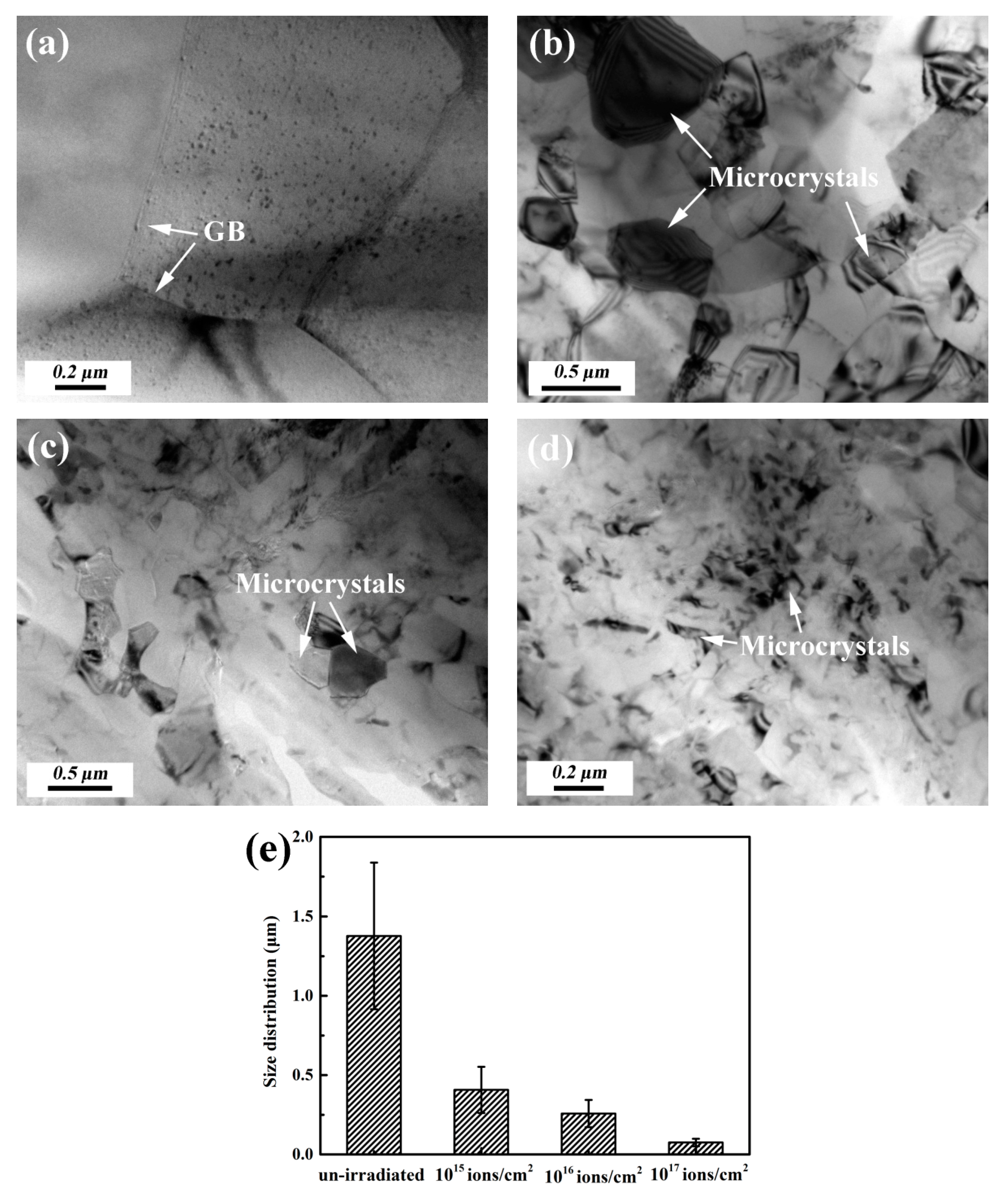
3.1. Microstructure of Un-Irradiated and Irradiated Samples

Figure 1a–d show the bright field TEM images of an un-irradiated sample and samples with 1015, 1016 and 1017 ions·cm−2 of irradiation. A typical microstructure of the Al-1060 alloy shows α-Al matrix with grain boundary (GB) and homogeneously distributed fine precipitates, as shown in Figure 1a. This agrees with the attractive properties of pure aluminum such as good plasticity. The grain size distributions of un-irradiated and irradiated samples were statistical analyzed, as shown in Figure 1e. The average size of a microcrystal in an un-irradiated sample is ~1.37 μm, as shown in Figure 1a. When the alloy was irradiated with 50 keV helium ion, an irradiated layer with a thickness of ~550 nm was produced (calculated by SRIM-2013 software). In the irradiated layer of a 1015 ions·cm−2 irradiated sample, microcrystals with an average size of ~0.41 μm were found, as shown in Figure 1b. Moreover, smaller grains were found in samples with higher fluence irradiation, as shown in Figure 1c,d. As shown in Figure 1e, the average size of the microcrystals in 1016 and 1017 ions·cm−2 were ~0.26 and ~0.08 μm. The results indicated that the grains were refined in irradiated samples. Since a mass of defects were produced in irradiated samples. These defects would affect the integrity of the crystal structure and induce lattice distortion and stress in irradiated samples. The phenomenon can be revealed by the X-ray diffraction patterns of un-irradiated and irradiated samples that are given in [16]. It can be seen that the (111) peak intensity of the irradiated sample is lower than that of an un-irradiated sample.
Figure 2a–e shows the primary microstructure observed in irradiated samples. In comparison with un-irradiated sample (shown in Figure 1a), it can be found that dislocations, dislocation loops and cavities were introduced in the irradiated layer. Figure 2a,b shows the configuration of dislocations and dislocation tangles in the interior of grain. The density of dislocations in this case is much higher than what was shown in the un-irradiated sample. Figure 2c exhibits projected dislocation loops which align along specific directions with different configurations. Patterns of projected dislocation loops change with the variation of angles between habit planes and the view screen, as dislocation loops lay on different habit planes. Rows of dislocation loops exhibiting elliptical contrast were obtained with an average size of ~70 nm. A cavity is another type of irradiation-induced defect, as shown in Figure 2d,e. In overfocus (Figure 2d) and underfocus (Figure 2e) of bright field micrographs, cavities with an average size of ~10 nm can be observed.
It is well known that the constant production of self-interstitial atoms (SIAs) and vacancies would introduce lattice distortion, dislocations and other kinds of defects in the irradiated layer of the sample, as shown in Figure 2. In order to reduce the free energy of the matrix, supersaturated vacancies and interstitials tend to accumulate on {111} planes by means of atomic scale diffusion and aggregation. In particular, the accumulated point defects would act as nucleation sites for the formation of dislocation loops and cavities [20,21]. It is noted that transformation of vacancy clusters to V-loops will result in a contraction of the material and induce tensile stress in the direction of the Burgers vector. Similarly, with the formation of I-loops, compression stress is induced. Here, it is suggested that the expansion or shrinkage of the loops are associated with the impact of stress as well as absorption of point defects. Moreover, irradiation-induced stress is recognized as the main factor which facilitates the interaction and growth of defects. The stress is related with lattice distortion and the formation of defects in the irradiated layer.

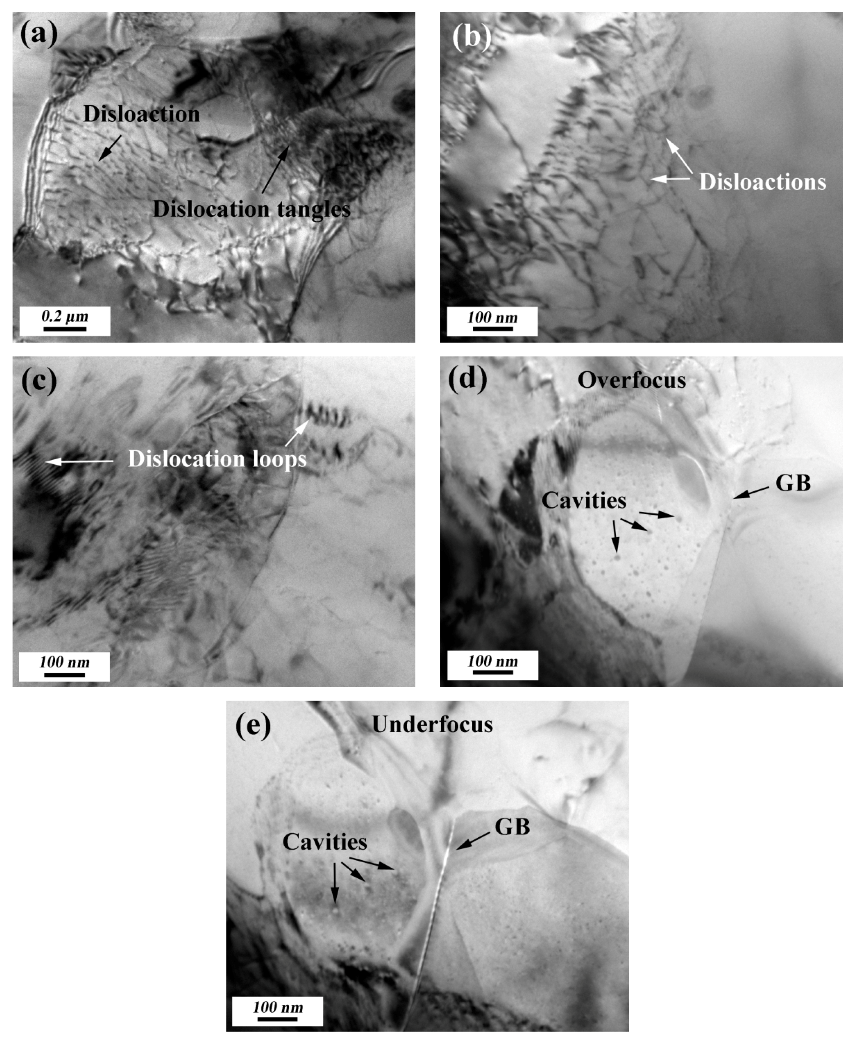
3.2. Dislocation Configuration in Irradiated Samples

As an increasing number of defects are produced in the surface layer during irradiation, dislocations can be driven by a defects-induced stress field [22]. Figure 3 shows the configuration of dislocation in irradiated samples. Figure 3a indicates the dislocation tangle configuration in the interior of grain. Figure 3b displays the dislocation wall formed in the 1016 ions·cm−2 irradiated sample. In addition, dislocations are found to pile up and tangle at GB; as shown in Figure 3c,d, the configuration of an array of approaching dislocations pass through GB. In this case, it is considered that the accumulation of dislocations increased the resolved shear stress to GB. In order to relieve the concentration of stress, a special slip system was activated by the GB which facilitated the movement of dislocations. In fcc metals, {111} semi-coherent interfaces contain either three sets of Shockley partial dislocations or three sets of full dislocations, depending on the stacking fault energy [23]. The high stacking fault energy of aluminum promotes the nucleation of partial dislocation during movement, which removes the stacking fault defects on glide planes [24]. That is why no obvious stacking fault defects can be observed in the irradiated sample.

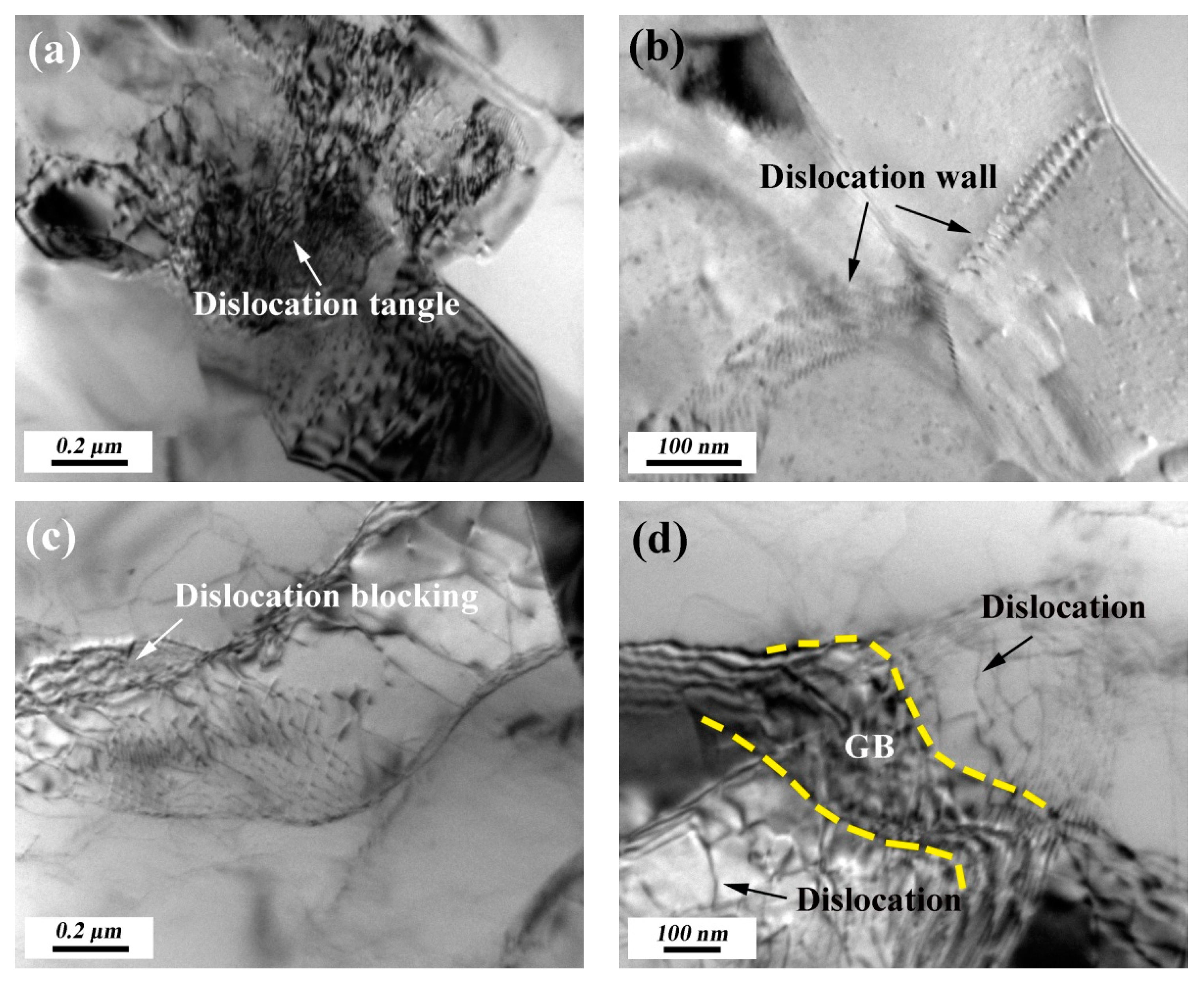
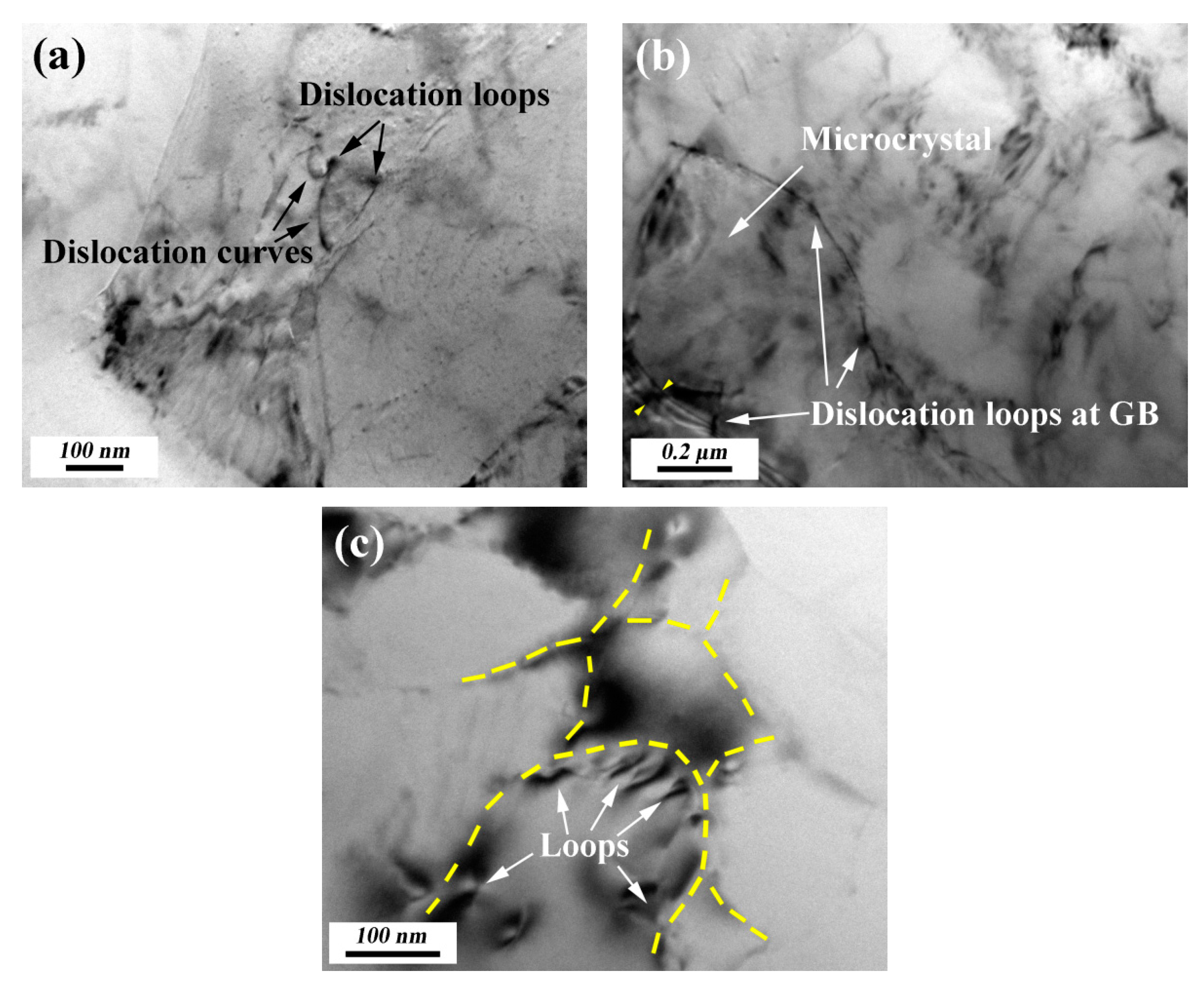
3.3. Dislocation-Defect Interaction in Irradiated Samples

What is noteworthy is that, irradiation-induced defects were acting as obstacles for moving dislocation. It has been known that dislocation can be easily driven at higher temperatures in a sample existing with applied stress. In this case, the interaction of moving dislocations with obstacles deserved more attention. As shown in Figure 3, the dislocation–dislocation interaction may form a dislocation tangle, dislocation wall, etc. Figure 4 shows the configuration of a moving dislocation meeting with obstacles such as a dislocation loop and a cavity in irradiated samples. Figure 4a shows that dislocations bow out as a result of inhibition of dislocation loops. Figure 4b shows the configuration of moving dislocations pinned with dislocation loops. As the number of dislocations increase at pinning sites, a change of strain field can be inferred from the distance variation of dislocations. In practice, loops with a larger size can block the motion of dislocations more effectively.
Furthermore, the rows of dislocation loops along specific directions revealed in Figure 1c and Figure 4c deserve more attention. As pre-existing crystal defects such as dislocations and GBs would act as sinks for trapping or recombining irradiation-induced interstitial atoms [25]. Moreover, interstitial atoms always have lower migration ability and formation energy than vacancies. Hence, a greater probability of capturing interstitial atoms would occur at sinks. As interstitial atoms captured with trapping sites, a favorable condition is created for the formation of vacancy clusters [26]. As shown in Figure 4b,c, dislocation loops are favored to form in the vicinity of GBs [27]. In addition, a group of dislocation loops have a better pinning effect than single ones, which facilitate the formation of microcrystals in irradiated samples.
Similarly, cavities can also perform as effective barriers in the process of dislocation movement, as shown in Figure 4b. Vacancy clusters can be present in the form of cavities in irradiated samples, as observed in Figure 1d,e. During helium ion irradiation, vacancies or vacancy clusters can trap helium atoms to form HenVm type vacancy clusters [28]. Attributed to the helium induced pressurization inside, these HenVm type vacancy clusters exhibited more stability than empty vacancy clusters [29]. Moreover, irradiation enhanced the diffusion ability of helium atoms and vacancy, which accelerated HenVm complex nucleation and coalescence. Then, cavities formed and grew into bigger ones. Cavities formed in irradiated samples have the effect of blocking and pinning dislocation, as shown in Figure 5b. Figure 5b shows the tendency of small cavity coalescence into bigger ones. Similarly, with V-loops, cavities have drawing force on surrounding material, which would also introduce tensile stress in the irradiated layer. In addition, bigger cavities can enhance the barrier effect on moving dislocations, which will take longer time to climb over the bigger ones. Analogous conclusions were revealed in fcc metals simulated by a concurrent atomistic-continuum method, dislocations were also found to bow as a result of pinning on the original glide planes due to cavity strengthening [30,31]. Moreover, when cavities appear in a line, it can be ascertained that an ideal site was developed for the production of microcrystal boundary, as shown in Figure 5a. Accordingly, dislocation-defect interactions facilitated the forming of microcrystal in irradiated samples. In conclusion, irradiation induced basic defects (vacancies and interstitials) in irradiated samples. The diffusion and aggregation of point defects resulted in the forming of structural defects. Moreover, the defect–defect interactions facilitated the evolution of microstructure (involving microcrystal forming) in irradiated samples.

4. Conclusions

Microstructure variations of helium ion irradiated Al-1060 alloys were explored in this work. Irradiation-induced supersaturated point defects led to the formation of irradiation defects such as dislocations, dislocation loops and cavities in irradiated samples. Attributing to the dislocation-defects interactions, microcrystals were formed in the irradiated layer. Dislocation loops may expand or shrink by means of absorbing point defects. In addition, dislocation loops prefer to form in the vicinity of GBs due to the sink effect and high stacking fault of aluminum. Helium can stabilize the nucleation and growth of vacancy clusters. Meanwhile, cavities can grow by absorbing a vacancy cluster or a small cavity from an adjacent region. Both dislocation loops and cavities with bigger sizes would have a better barrier effect than smaller ones. In addition, the interaction between dislocation and irradiation defects was the primary mechanism for the production of microcrystal in irradiated samples.

Author Contributions

Conceptualization, H.W.; Methodology, H.W. and N.S.; Formal Analysis, H.W.; Investigation, H.W; Writing—Original Draft Preparation, H.W.; Writing—Review and Editing, H.W., S.Z., Q.J. and T.Y.

Funding

This work was supported by the Scientific Research Foundation of Taizhou University for the Introduction of Talents (TZXY2017QDJJ014), the sixteenth “Six talent peaks” of high-level talent selection and a training project of Jiangsu Province (XCL-265), the Natural Science Foundation of the Jiangsu Higher Education Institutions of China (18KJD430007), the college students’ innovation and entrepreneurship training project of Jiangsu province (201912917035Y and 201912917029Y), and the Fifth “311 High-level Talents Training Project” of Taizhou City.

Conflicts of Interest

The authors declare no conflict of interest.

References

  1. Yi, X.; Jenkins, M.L.; Hattar, K.; Philip, D.E.; Steve, G.R. Characterisation of radiation damage in W and W-based alloys from 2 MeV self-ion near-bulk implantations. Acta Mater. 2015, 92, 163–177. [Google Scholar] [CrossRef] [Green Version]
  2. Wang, C.; Shan, D.; Guo, B.; Xue, J.; Zhang, H. Effect of nano-crystals at surfaces induced by ion beam irradiation on the tribological behaviour in microforming. Vacuum 2013, 89, 267–270. [Google Scholar] [CrossRef]
  3. Gao, J.; Yabuuchi, K.; Kimura, A. Ion-irradiation hardening and microstructural evolution in F82H and ferritic alloys. J. Nucl. Mater. 2019, 515, 294–302. [Google Scholar] [CrossRef]
  4. Wan, F.; Zhan, Q.; Long, Y.; Yang, S.; Zhang, G.; Du, Y.; Jiao, Z.; Ohnuki, S. The behavior of vacancy-type dislocation loops under electron irradiation in iron. J. Nucl. Mater. 2014, 455, 253–257. [Google Scholar] [CrossRef]
  5. Khan, A.K.; Yao, Z.; Daymond, M.R.; Holt, R.A. Effect of foil orientation on damage accumulation during irradiation in magnesium and annealing response of dislocation loops. J. Nucl. Mater. 2012, 423, 132–141. [Google Scholar] [CrossRef]
  6. Zhang, H.K.; Yao, Z.W.; Morin, G.; Griffiths, M. TEM characterization of in-reactor neutron irradiated CANDU spacer material Inconel X-750. J. Nucl. Mater. 2014, 451, 88–96. [Google Scholar] [CrossRef]
  7. Li, N.; Hattar, K.; Misra, A. In situ probing of the evolution of irradiation-induced defects in copper. J. Nucl. Mater. 2013, 439, 185–191. [Google Scholar] [CrossRef]
  8. Satoh, Y.; Matsuda, Y.; Yoshiie, T.; Kawai, M.; Matsumura, H.; Iwase, H.; Abe, H.; Kim, S.W.; Matsunaga, T. Defect clusters formed from large collision cascades in fcc metals irradiated with spallation neutrons. J. Nucl. Mater. 2013, 442, S768–S772. [Google Scholar] [CrossRef]
  9. Druzhkov, A.P.; Arbuzov, V.L.; Perminv, D.A. The effect of neutron irradiation dose on vacancy defect accumulation and annealing in pure nickel. J. Nucl. Mater. 2012, 421, 58–63. [Google Scholar] [CrossRef]
  10. Yang, Z.B.; Watanabe, S. Dislocation loop formation under various irradiations of laser and/or electron beams. Acta Mater. 2013, 61, 2966–2972. [Google Scholar] [CrossRef]
  11. Caturla, M.J.; Rybia, T.D.; Fluss, M. Modeling microstructure evolution of fcc metals under irradiation in the presence of He. J. Nucl. Mater. 2003, 323, 163–168. [Google Scholar] [CrossRef]
  12. Di, S.; Yao, Z.W.; Daymond, M.R.; Zu, X.T.; Peng, S.M.; Gao, F. Dislocation-accelerated void formation under irradiation in zirconium. Acta Mater. 2015, 82, 94–99. [Google Scholar] [CrossRef] [Green Version]
  13. Draganski, M.A.; Finkman, E.; Gibson, B.C.; Fairchild, B.A.; Ganesan, K.; Nabatova-Gabain, N.; Tomljenovic-Hanic, S.; Greentree, A.D.; Prawer, S. The effect of gallium implantation on the optical properties of diamond. Diam. Relat. Mater. 2013, 35, 47–52. [Google Scholar] [CrossRef]
  14. Wan, H.; Ding, Z.; Wang, J.; Yin, Y.; Guo, Q.; Gong, Y.; Zhao, Z.; Yao, X. Effects of helium ion irradiation on the high temperature oxidation resistance of Inconel 718 alloy. Surf. Coat. Technol. 2019, 363, 34–42. [Google Scholar] [CrossRef]
  15. Jayalakshmi, G.; Saravanan, K.; Balakumar, S.; Balasubramanian, T. Swift heavy ion induced modifications in structural, optical & magnetic properties of pure and V doped ZnO films. Vacuum 2013, 95, 66–70. [Google Scholar] [CrossRef]
  16. Wan, H.; Si, N.; Chen, K.; Wang, Q. Strain and structure order variation of pure aluminum due to helium irradiation. RSC Adv. 2015, 5, 75390–75394. [Google Scholar] [CrossRef]
  17. Wan, H.; Si, N.; Wang, Q.; Zhao, Z. Morphology variation, composition alteration and microstructure changes in ion-irradiated 1060 aluminum alloy. Mater. Res. Express 2018, 5, 026501. [Google Scholar] [CrossRef]
  18. Martin, G.; Garcia, P.; Sabathier, C.; Van Brutzel, L.; Dorado, B.; Garrido, F.; Maillard, S. Irradiation-induced heterogeneous nucleation in uranium dioxide. Phys. Lett. A 2010, 374, 3038–3041. [Google Scholar] [CrossRef]
  19. Jin, S.; Guo, L.; Yang, Z.; Fu, D.; Liu, C.; Xiao, W.; Tang, R.; Liu, F.; Qiao, Y. Microstructural evolution in nickel alloy C-276 after Ar+ ion irradiation. Nucl. Instrum. Method Phys. Res. Sect. B 2011, 269, 209–215. [Google Scholar] [CrossRef]
  20. Zinkle, S.J. Effect of H and He irradiation on cavity formation and blistering in ceramics. Nucl. Instrum. Method Phys. Res. Sect. B 2012, 286, 4–19. [Google Scholar] [CrossRef]
  21. Liu, L.; Liu, Q.; Wang, Z.; Tang, Z. Interstitial clusters on Σ = 11(113) grain boundary in copper: Geometric structure, stability, and ability to annihilate vacancies. Phys. Lett. A 2016, 380, 621–627. [Google Scholar] [CrossRef]
  22. Ke, J.H.; Boyne, A.; Wang, Y.; Kao, C.R. Phase field microelasticity model of dislocation climb: Methodology and applications. Acta Mater. 2014, 79, 396–410. [Google Scholar] [CrossRef]
  23. Shao, S.; Wang, J.; Misra, A.; Hoagland, R.G. Spiral patterns of dislocations at nodes in (111) semi-coherent FCC interfaces. Scientific reports. Sci. Rep. 2013, 3, 2448. [Google Scholar] [CrossRef] [PubMed]
  24. Terentyev, D.; Bakaev, A.; Osetsky, Y.N. Interaction of dislocations with Frank loops in Fe–Ni alloys and pure Ni: An MD study. J. Nucl. Mater. 2013, 442, S628–S632. [Google Scholar] [CrossRef]
  25. Wan, H.; Si, N.; Zhao, Z.; Wang, J.; Zhang, Y. Study of irradiation induced surface pattern and structural changes in Inconel 718 alloy. Mater. Res. Express 2018, 5, 056503. [Google Scholar] [CrossRef]
  26. Zhang, H.; Yao, Z.; Daymond, M.R. Cavity morphology in a Ni based superalloy under heavy ion irradiation with hot pre-injected helium. II. J. Appl. Phys. 2014, 115, 103509. [Google Scholar] [CrossRef]
  27. Mizuno, K.; Morikawa, K.; Okamaoto, H.; Hashimoto, E. Row of dislocation loops as a vacancy source in ultrahigh-purity aluminum single crystals with a low dislocation density. Trans. Mater. Res. Soc. Jpn. 2014, 3, 169–172. [Google Scholar] [CrossRef]
  28. Zhang, H.; Yao, Z.; Daymond, M.R. Cavity morphology in a Ni based superalloy under heavy ion irradiation with cold pre-injected helium. I. J. Appl. Phys. 2014, 115, 103508. [Google Scholar] [CrossRef]
  29. Ou, X.; Anwand, W.; Kögler, R.; Zhou, H.-B.; Richter, A. The role of helium implantation induced vacancy defect on hardening of tungsten. J. Appl. Phys. 2014, 115, 123521. [Google Scholar] [CrossRef] [Green Version]
  30. Wan, H.; Si, N.; Wang, Q.; Chen, K.; Liu, G. Surface morphology alteration, microstructure variation and dislocation-precipitate interactions of Inconel 718 due to helium ions irradiation. Mater. Charact. 2017, 127, 95–103. [Google Scholar] [CrossRef]
  31. Xiong, L.; Xu, S.; McDowell, D.L.; Chen, Y. Concurrent atomistic–continuum simulations of dislocation–void interactions in fcc crystals. Int. J. Plast. 2015, 65, 33–42. [Google Scholar] [CrossRef]
Figure 1. Bright field TEM images of samples without and with irradiation: (a) un-irradiated sample; (b) 1015 ions·cm−2; (c) 1016 ions·cm−2; and (d) 1017 ions·cm−2. (e) grain size distribution of un-irradiated and irradiated samples.
Coatings 09 00516 g001
Figure 2. Bright field TEM images of samples with 1016 ions·cm−2 irradiation: (a,b) dislocation and dislocation tangle; (c) dislocation loop; and (d,e) cavity.
Coatings 09 00516 g002
Figure 3. Bright field TEM images of dislocation configuration in 1016 ions·cm−2 irradiated sample: (a) dislocation tangle; (b) dislocation wall; (c) dislocation blocking; and (d) dislocation pass through GB.
Coatings 09 00516 g003
Figure 4. Interaction of dislocation with dislocation loop: (a) dislocations pinned with dislocation loops, 1015 ions·cm−2; (b,c) dislocation loops near GB, 1016 ions·cm−2.
Coatings 09 00516 g004
Figure 5. (a) dislocation-cavity interaction, 1016 ions·cm−2; (b) bigger cavity, 1016 ions·cm−2.
Coatings 09 00516 g005

