Article

Influence of Growth Defects on the Corrosion Resistance of Sputter-Deposited TiAlN Hard Coatings

1
Department of Thin Films and Surfaces, Jožef Stefan Institute, Jamova cesta 39, SI-1000 Ljubljana, Slovenia
2
Interkorn d.o.o., Gančani 94, SI-9231 Beltinci, Slovenia
3
Faculty of Mechanical Engineering, University of Maribor, Smetanova 17, SI-2000 Maribor, Slovenia
*
Author to whom correspondence should be addressed.
Dr. Darja Kek Merl passed away before publication was completed.
Coatings 2019, 9(8), 511; https://doi.org/10.3390/coatings9080511
Submission received: 10 July 2019 / Revised: 30 July 2019 / Accepted: 9 August 2019 / Published: 12 August 2019
(This article belongs to the Special Issue Anticorrosion Protection of Nonmetallic and Metallic Coatings)

Abstract

:
In this work, the causes of porosity of TiAlN hard coatings sputter deposited on D2 tool steel were studied since its corrosion resistance is mainly affected by imperfections within the coating (e.g., pinholes, pores, crevices). The corrosion test was performed in a chlorine solution using electrochemical impedance spectroscopy. The coating morphology of growth defects before and after the exposure was studied by scanning electron microscopy (SEM), while focused ion beam (FIB) was used to make series of cross-sections through individual selected defects. We confirm that pitting corrosion is closely related to the through-thickness growth defects. It was also found that in the case of nodular defects, the intensity of corrosion depends on the shape of the seed.

1. Introduction

Hard coatings prepared by physical vapor deposition (PVD) are widely used to improve the wear resistance of all types of tools, to reduce the friction of machine parts, for decorative applications, and for protection of implants and medical instruments [1,2,3]. In the majority of these applications, the corrosion attack of tools and components occurs by the corrosive environment to which they are exposed (e.g., corrosive gases, technical reagents, cooling and lubricant liquids, body fluids, sea water). In general, such corrosion attacks drastically reduce the lifetime of coated tools and components.
Although the PVD hard coatings have a very good corrosion resistance, they do not provide good corrosion protection of the less noble substrate materials [4,5]. The corrosive attack of coated components is caused by imperfections within the coating [3,4,6,7,8,9,10,11,12,13]. It is well known that due to the line-of-sight transfer of the vapor flux during the sputtering process, many intrinsic defects are generated in the coating [14]. Morphological imperfections caused by the shadowing effect include columnar structures, pinholes, pores, void zones around nodular defects or droplets (crevices), microcracks, grain boundaries, and other discontinuities. All these microstructure imperfections can significantly affect their corrosion resistance, if they extend throughout the whole thickness of the coating. When the coated substrate is exposed to a corrosive medium, the electrolyte penetrates to the substrate through such defects, driven by the capillary forces. In the case of a less noble substrate material, this leads to the formation of local galvanic corrosion between the substrate (acting as an anode) and the coating (acting as a cathode) [5]. The corrosion reaction takes place under a closed electrical circuit in which the current flow is based on the electrical (electron) conductivity of the coating on one hand and on the ionic conductivity of the electrolyte (it is conductive due to the presence of dissolved cations and anions) on the other hand [15]. Corrosion is localized to the defect area, where the anodic dissolution of the exposed substrate material appears. The corrosion attack is more intense if the difference of the electrochemical potential between the coating and the substrate in the selected electrolyte is larger. Since the area of the cathode (coating) is much larger than that of the anode (substrate), pitting corrosion is the predominant corrosion type. For the same reason, the corrosion process in the pores and pinholes is fast. Pits which are present in the substrate material are extending radially from the pores, resulting in cracking and removal of the coating above by flaking (blistering). In such a way, pitting corrosion has a devastating effect on coated tools or components.
Many ways to improve the corrosion resistance are described in the literature [4,5,16]. In general, any way which reduces the porosity of the coating improves the corrosion resistance at the same time. Although it is practically impossible to eliminate the coating defects completely, their density can be reduced by proper pretreatment of the substrate surface, coating design, and modification of the deposition process. A lot of research has been devoted to this problem in the past. It was found that the substrate surface roughness must be as low as possible since the higher roughness results in less complete coverage of the substrate with the coating material (due to the shadowing effects during the PVD coating growth). It was also found that the corrosion resistance increases with increasing coating thickness due to reduced mass transport between the bottom of the pinhole and the corrosive environment. Jehn estimated that a satisfactory corrosion resistance of the coating can be achieved only if its thickness is more than 14 µm [4].
More recently, the sealing of the PVD hard coatings with only a few-nanometers-thick (oxide) film prepared by low-temperature atomic layer deposition (ALD) technique was introduced [17,18]. This technique offers the deposition of uniform, conformal, and high-density thin films with a thickness of only a few nanometers. Such a thin layer (e.g., Al2O3) blocks pinholes and other defects in the PVD hard coating.
The next approach for improvement of corrosion resistance is the addition of a sacrificial element (e.g., Mg) to conventional hard coatings [19].
In the past, efforts were made to improve the corrosion resistance of PVD hard coatings by appropriate coating architecture (deposition of interlayers, multilayer coatings, duplex coatings) [20,21,22]. Using these approaches, the improvement of corrosion performance is the result of the synergistic effect of two or more materials.
The corrosion behavior of PVD hard coatings also depends on the coating microstructure. In general, PVD hard coatings designed for corrosion protection should possess a dense and uniform microstructure (fine-grained or amorphous). The columnar microstructure is not desirable because the interfaces between adjacent columns can act as pathways for corrosive media to reach the substrate.
The growth of the columnar microstructure of the PVD hard coating can be interrupted by intermediate ion etching of the growing coating [23,24]. It is assumed that ion etching leads to a denser coating, due to defect-induced renucleation and improved adatom mobility. New nucleation sites for subsequent film growth are also generated and a fine-grained microstructure is formed. In such a way, the path length for corrosive medium is increased. By ion etching, the material from grain flanks is redeposited to the pore walls resulting in a decrease of porosity.
Nitride hard coatings lose their columnar microstructure and become denser if doped by oxygen [25]. Additionally, with increasing oxygen content, the electrical conductivity considerably decreases. Therefore, the iron dissolving is strongly reduced because the electrons cannot travel through the coating.
Another good approach to obtain a dense microstructure of the coatings and to overcome intrinsic defects is to add other elements (Si or B) into the hard coatings to form nanocomposite coatings with nanosized crystallites surrounded by the matrix [23].
Yet another new strategy is based on high-power impulse magnetron sputtering (HiPIMS), which allows an energetic condensation [24,25,26,27]. Such PVD coatings have a higher density, better adhesion, and smooth surface (free of macroparticles), while pinholes can be closed by higher adatom mobility. An additional advantage is etching with metal ions produced by the HiPIMS plasma. The metal ions do not only etch the substrates, they are also implanted in the near-surface layer of the substrate. Such metal-ion-implanted interlayer is normally beneficial since it improves adhesion and corrosion resistance of the coating.
While the mechanism of pitting corrosion of coatings is quite well described [4,7,9], we know only a little about the formation of microstructure imperfections and their influence on the corrosion resistance of hard coatings. Previously, we tried to explain the origin of the growth defects in PVD hard coatings [28,29]. In this paper, we focused on the identification of those growth defects in sputter-deposited TiAlN hard coatings, where the pitting corrosion occurs after it has been exposed to the corrosive medium.

2. Experiment

The industrial magnetron sputtering system (CC800/7, CemeCon, Wurselen, Germany) was used for deposition of the TiAlN hard coating. The thickness of the coatings was around 4.2 µm, using a twofold planetary rotation. The samples analyzed in this study consisted of test plates made of D2 tool steel. They were first ground and polished up to the roughness of about 10 nm (Ra). Before deposition, they were cleaned in detergents and ultrasound, rinsed in deionized water, and dried in hot air. In the vacuum chamber, they were first heated to about 450 °C, then cleaned in situ by ion etching. Standard TiAlN coating was deposited by DC sputtering of four segmental Ti–Al targets at 8 kW each. The working pressure was 750 mPa (N2, Ar, and Kr atmosphere), and the bias voltage was −100 V. After two-thirds of the deposition time, the deposition process was interrupted for an intermediate plasma etching process. The intermediate etching provides fine-grained and less porous microstructure (less pronounced columnar microstructure).
A corrosion test of TiAlN deposited on D2 tool steel, using electrochemical impedance spectroscopy (EIS), was performed in 0.5 M NaCl solution at pH = 3.8 using a Parstat 2263 spectroscope (Princeton Applied Research, Oak Ridge, United States of America). The test specimen employed as a working electrode was exposed to the solution for 96 h.
The coating microstructure and defect morphology, before and after the exposure, were studied in a planar surface view and in focused ion beam (FIB) cross-sectional view. We used the FIB integrated into the Helios Nanolab 650 electron microscope (FEI BV; now FEI SAS, part of Thermo Fisher Scientific, Merignac, France). The primary opening, required for further observations of cross-sections, with dimensions 22 × 12 × 12 µm3, was ion-milled at 20 nA beam current, while the acceleration voltage of ions was 30 kV. The sections of the material were removed from the specimen surface by sputtering in three steps: rough removal (30 keV/65 nA), medium polishing (30 keV/20 nA), and fine polishing (30 keV/1 nA). After all three steps were completed, the image of the cross-section was taken using 10 pA ion beam current. After imaging, the next slice of the sample with a thickness of about 0.9 µm was removed by ion milling and another image of the new cross-section was acquired. This procedure was repeated until the entire site of interest was examined.

3. Results

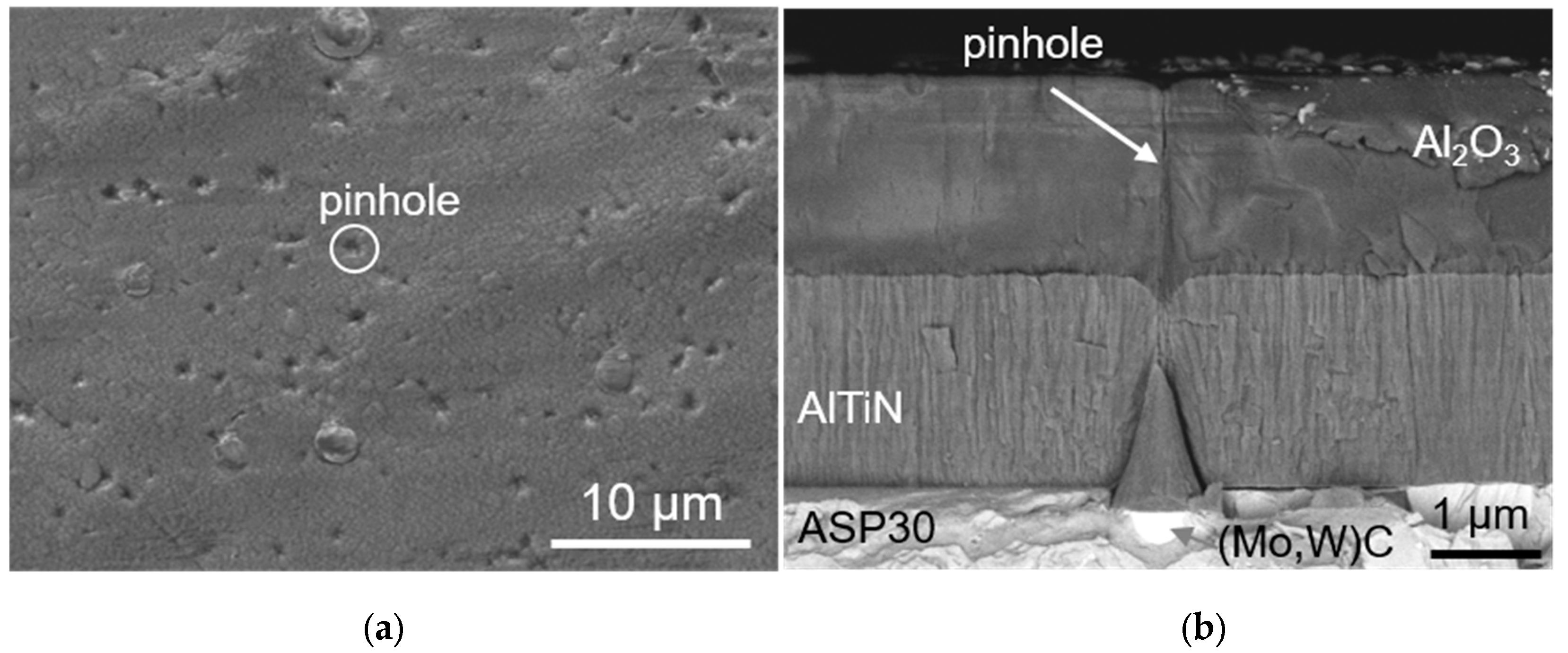
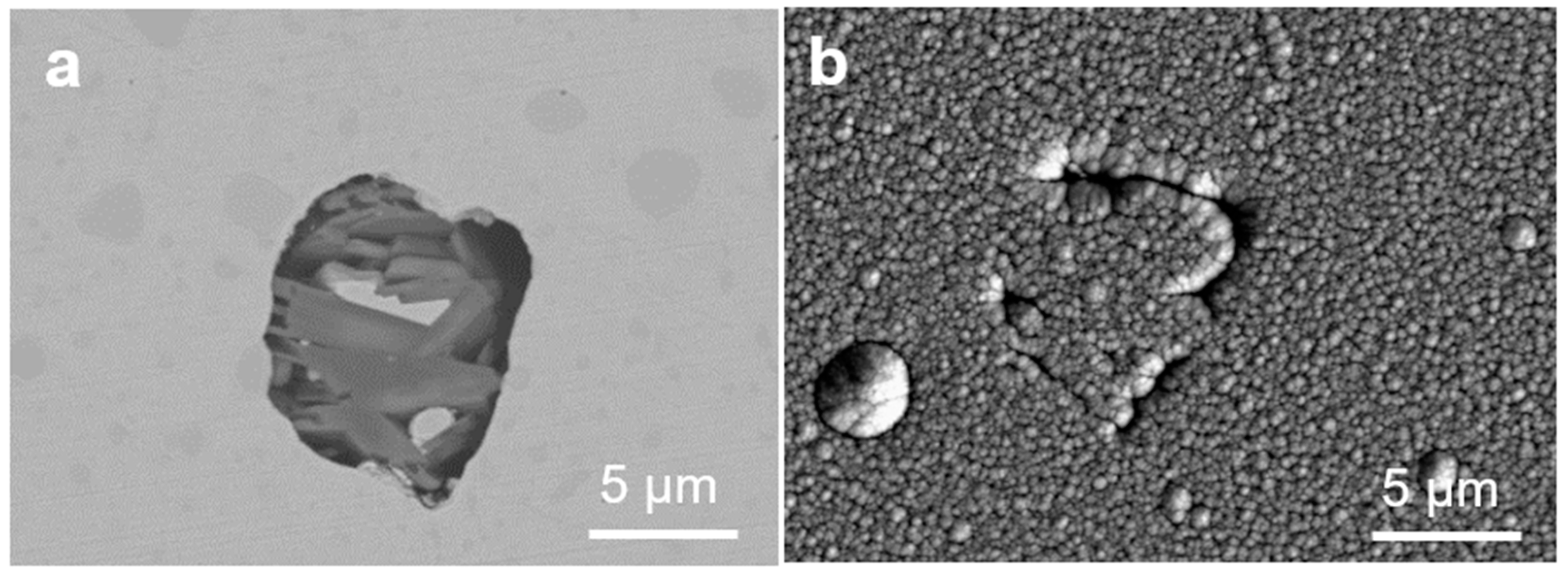
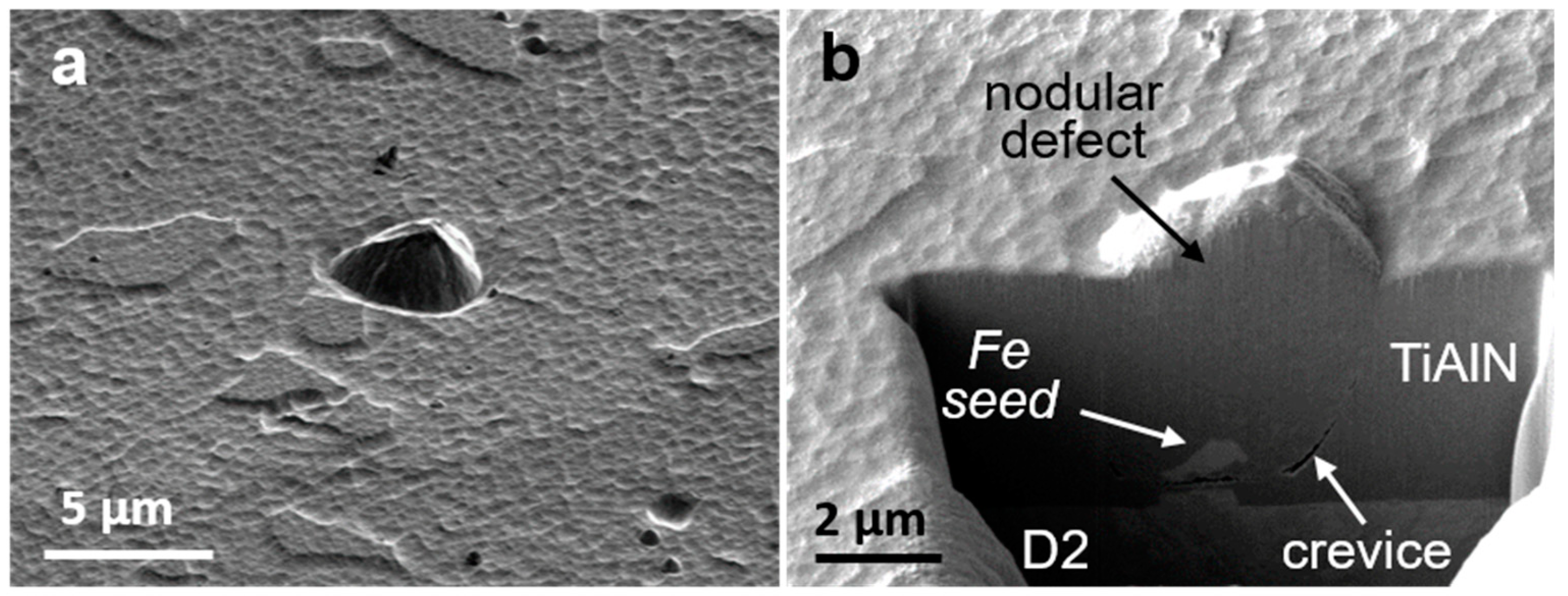
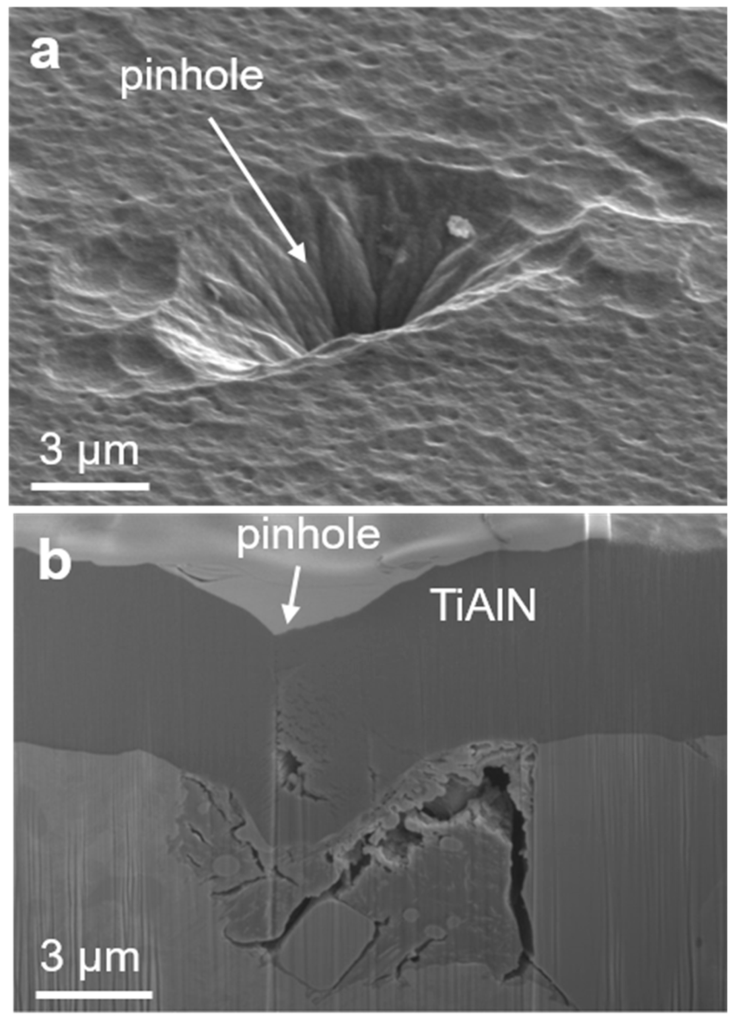
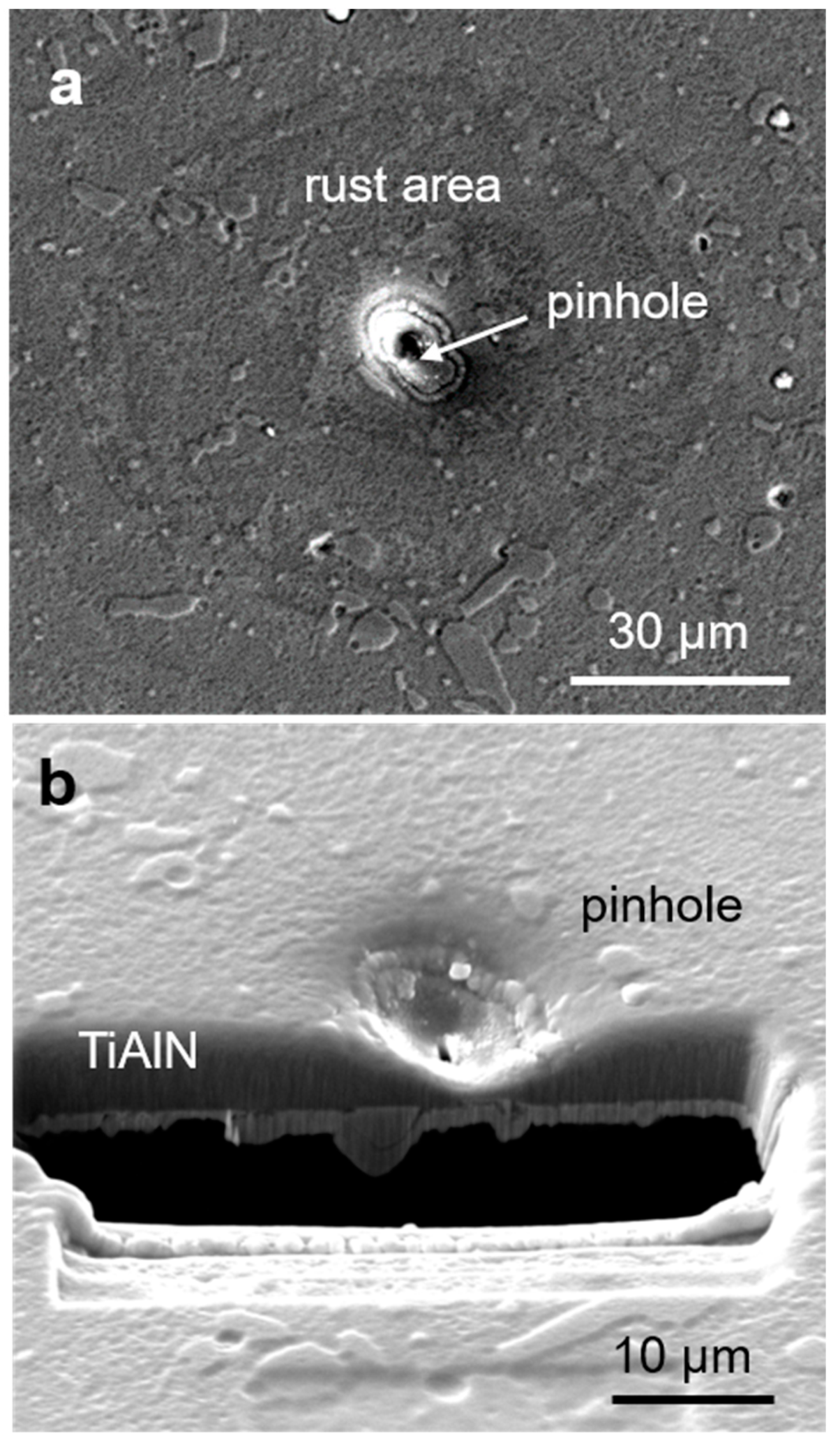
3.1. Mechanisms of Pinhole Formation

As discussed in the introduction, one major drawback of PVD hard coatings is that they are not free from growth defects. Besides nodular and flake defects, open and closed pores, pinholes have been observed on the sputter-deposited TiAlN hard coating. All these defects have different shapes and sizes. However, pitting corrosion does not occur on all these sites. The question is how to identify which defects are responsible for pitting corrosion. It can only be those defects that are extending through the coating down to the coating–substrate interface. At least four groups of growth defects which can cause the pitting corrosion can be identified. The causes for their formation are discussed in more detail in the following text.

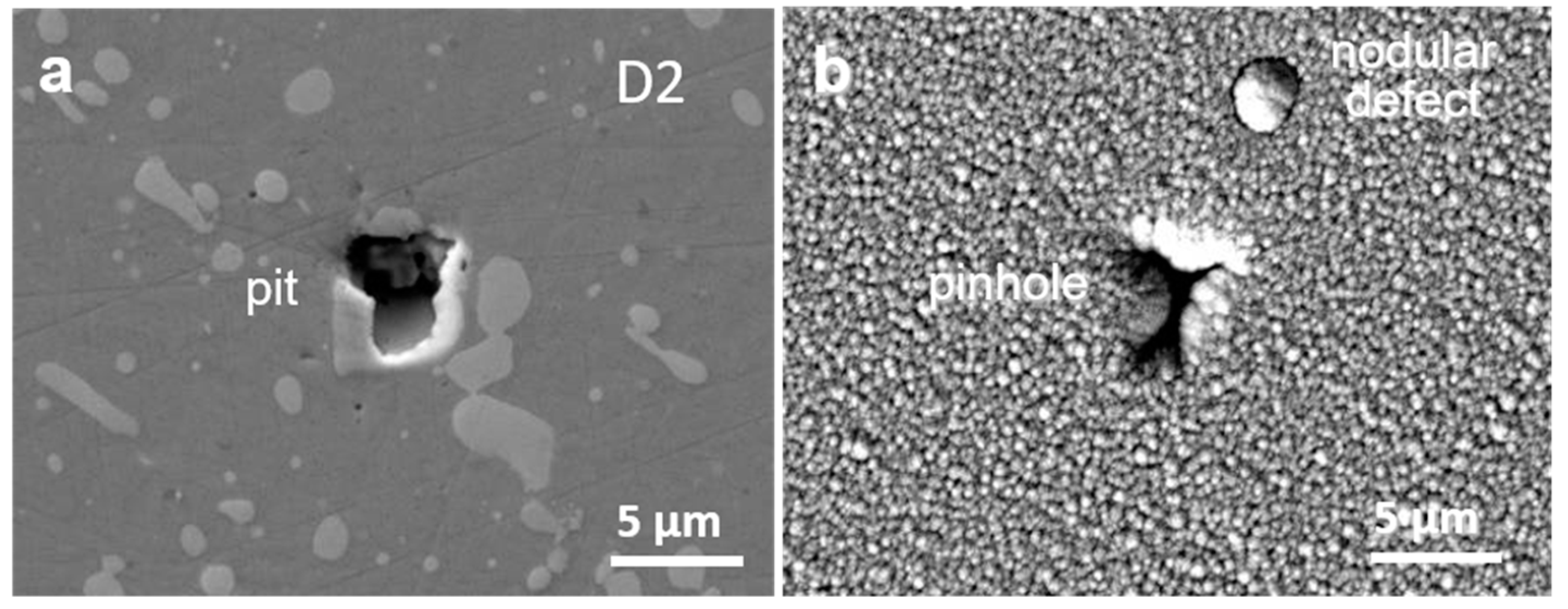
3.1.1. Pinhole Formation at Pits in the Substrate

During grinding and polishing of tool steel substrates, shallow protrusions are formed at the carbides because they are harder than the ferrous matrix [30]. Because of the high shear stress during polishing, a part of protruded carbides can be torn out, leaving a pit in the substrate (Figure 1a). Due to the line-of-sight nature of the PVD deposition process, a part of the pit (hole) wall remains uncovered, while a pinhole is formed in the coating (Figure 1b). Whether a pinhole will be formed or not depends on the pit depth-to-width ratio. In the case of high aspect ratio (a narrow but deep pit), the deposition starts to coat the upper sidewalls and corners of the feature, which shadows the lower area from subsequent deposition. During the coating growth, the hole’s opening narrows, and if the PVD coating is thick enough, coatings from both sides of the hole touch and close the opening, forming an isolated pore (keyhole). However, a discontinuity of microstructure is preserved through the growing coating, extending up to the coating surface. The pinhole will not be able to close up if the width of the pit is comparable to the final coating thickness. In the case of a low aspect ratio (a laterally large but shallow pit), an open pinhole will be formed.

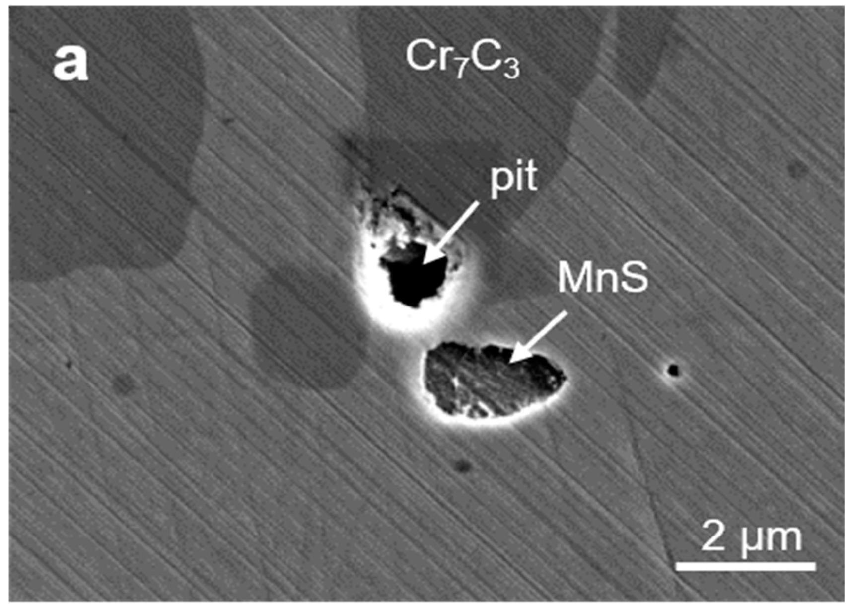
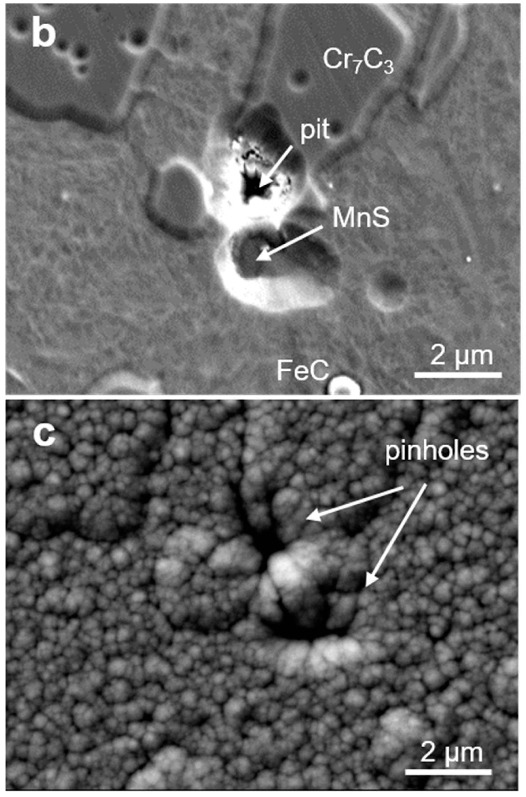
3.1.2. Pinhole Formation at Carbide and Nonmetallic Inclusions

During polishing of tool steel substrates, shallow protrusions are formed at the inclusions which are harder than the ferrous matrix (e.g., carbides and oxides), while shallow craters are formed at the inclusions which are softer (e.g., MnS) [29]. The reason is the difference in the removal rates of different inclusions in comparison to the ferrous matrix. Additional topographical changes occur during ion etching due to different etching rates of various phases in the tool steel material. Thus, the total geometrical extension (up or down) of the surface irregularities from the ferrous matrix level depends on the differences in both the removal rate and ion etching rate. Consequently, shallow craters (e.g., on the sites of Cr7C3, MnS) and protrusions (e.g., oxides) are formed. During the deposition process, all morphological features formed during the previous steps are transferred through the coating. Due to the shadowing effect, pinholes can be formed at positions of shallow craters (Figure 2). Formation of such a type of pinhole is displayed in Figure 2 for Al2O3/TiAlN double-layer hard coating sputter deposited on powder metallurgical (PM) tool steel substrate ASP30 in the CC800/9 deposition system. The bottom TiAlN layer was made in a similar way to that in CC800/7 (CemeCon, Wurselen, Germany), while the oxide top layer was prepared in the oxygen atmosphere by magnetron sputtering, operated in pulsed mode.
One of the origins of pinhole formation is also nonmetallic inclusions (e.g., MnS, Al2O3) in steel substrates. Such inclusions are formed as a result of the steelmaking process and are present in all types of steels. The removal rates (during polishing) and etching rates (during ion etching) of the inclusions are different in comparison with the ferrous matrix. In the case of MnS inclusions, for example, both rates are larger and therefore shallow craters are formed after both substrate pretreatments (Figure 3). Consequently, during the deposition process, such a shallow crater can be a starting point for a pinhole formation. Due to the generally poor contact between the inclusion surface and hard coating, a strong columnar growth with an extensive mesh of pinholes was observed. In the case of an Al2O3 inclusion with a complex microstructure (Figure 4a), a series of pinholes (Figure 4b) has formed on its boundary with the ferrous matrix.

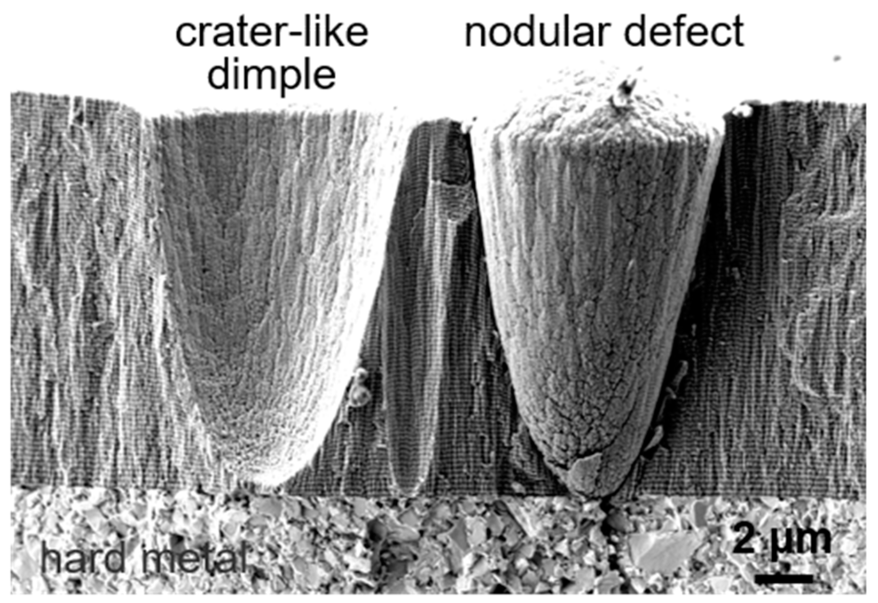
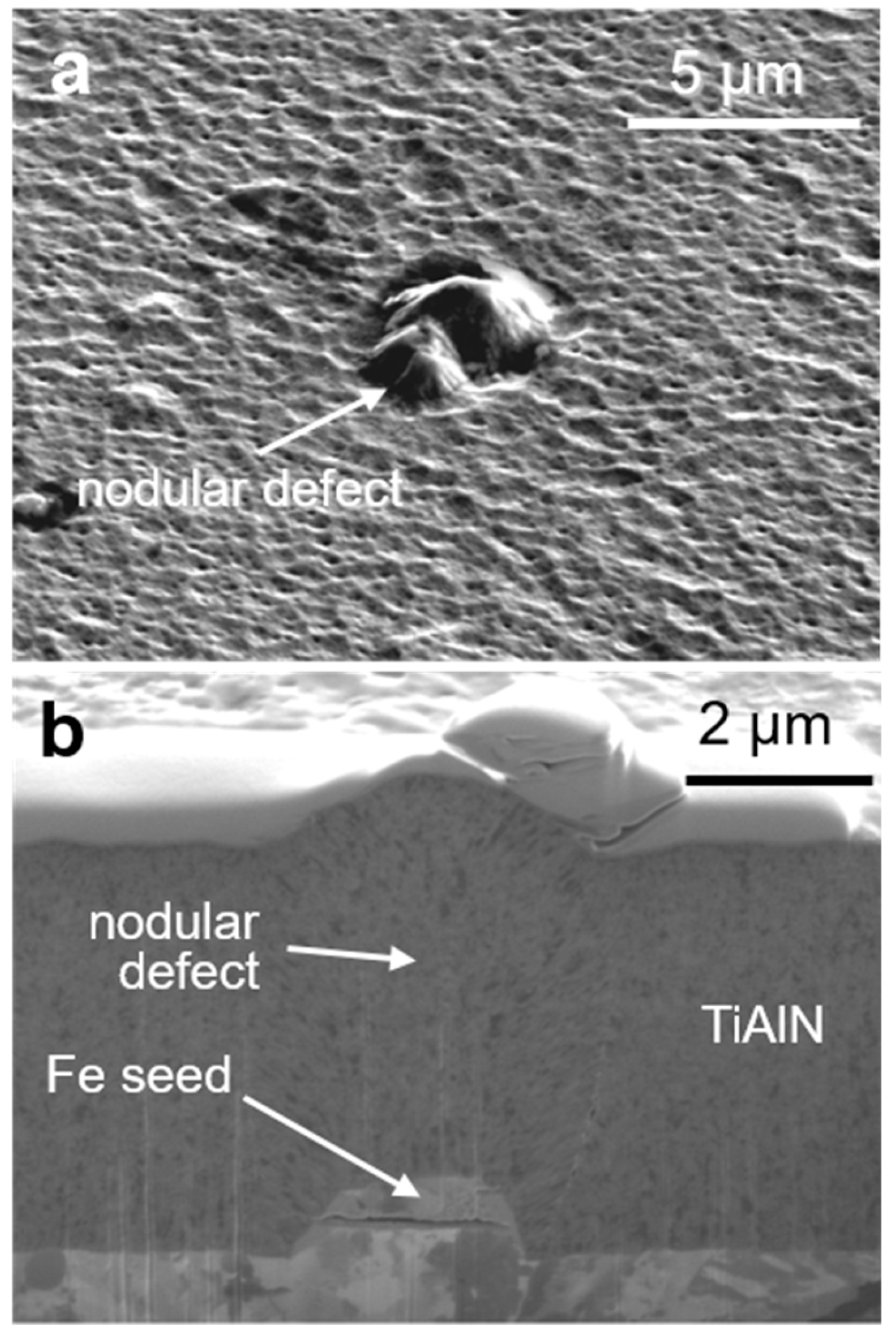
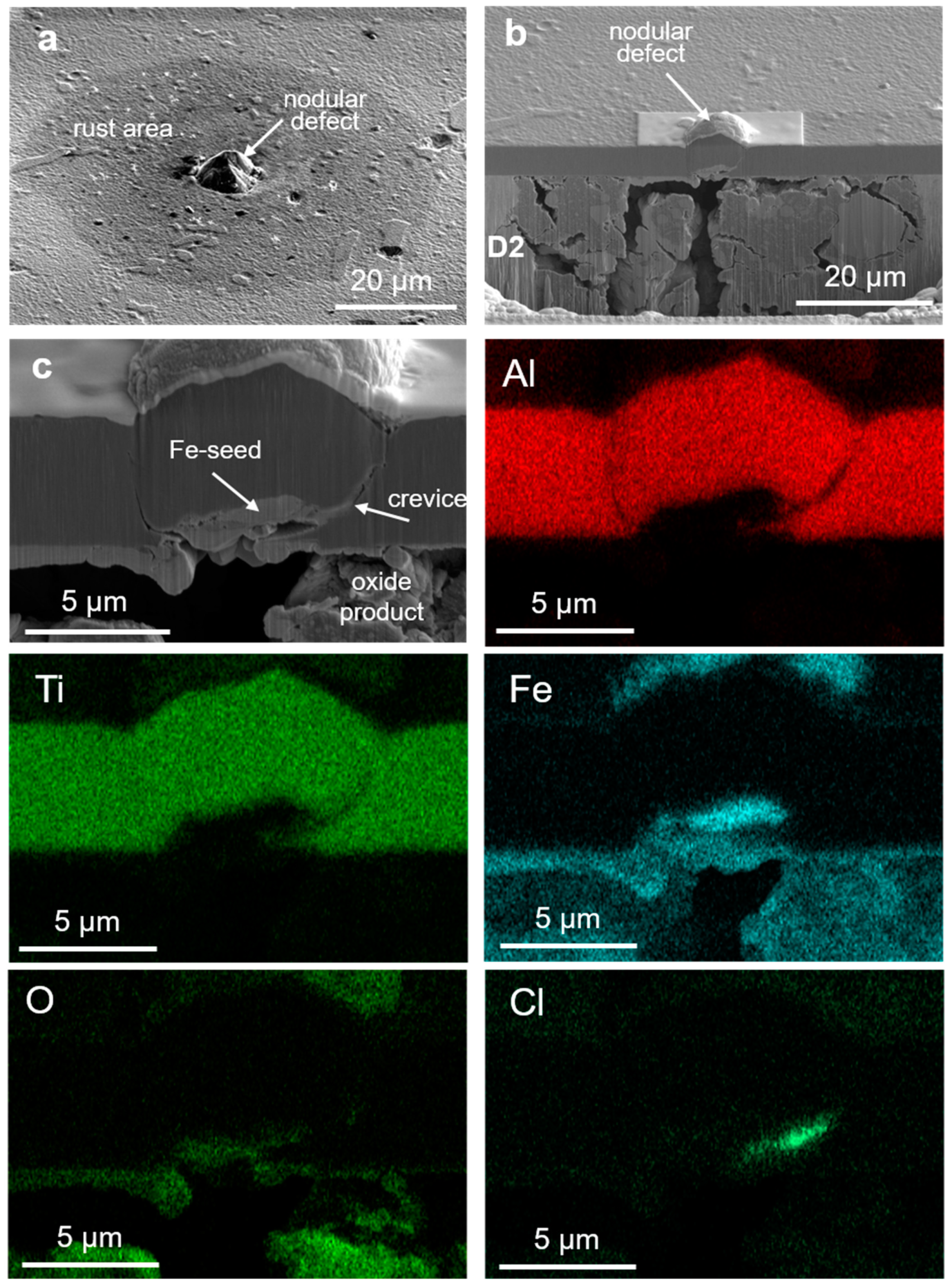
3.1.3. Pinhole Formation at Nodular Defects

Even at the sites where nodular (Figure 5 and Figure 6) and flake defects started to grow on the substrate surface, some degree of porosity remained. Nodular and flake defects are formed during deposition of PVD hard coating on the seed particles, which are either foreign or flake particles attached to the substrate surface before starting the deposition process. In the case of a nodular defect, shown in Figure 5a, the seed particle is based on iron. A step-like feature on the substrate surface is clearly visible (Figure 5b). The appearance of such a step indicates that the seed already existed on the substrate surface before ion etching. Therefore, this area was not exposed for etching. In general, the contact of the seed particle with the substrate is very poor, while the nodular defect is more or less separated from the coating matrix (Figure 5b). The border between the nodular defect and the undisturbed coating is therefore composed of a series of pinholes. The corrosion behavior of a hard coating does not only depend on the defect size, but also on the shape of the seed. Balzer et al. reported that the shape of the seed strongly affects the defect growth and the porosity of the coating matrix–defect boundary [31]. For a through-coating nodular and flake defect, the corrosion attack is initiated by galvanic or crevice corrosion. The void zones around nodular defects allow the solution penetration down to the steel substrate surface. If the formation of nodular defects is caused by droplets, then galvanic corrosion caused by differences of binding energy and chemical composition between the coating matrix and the droplet can also appear [6].

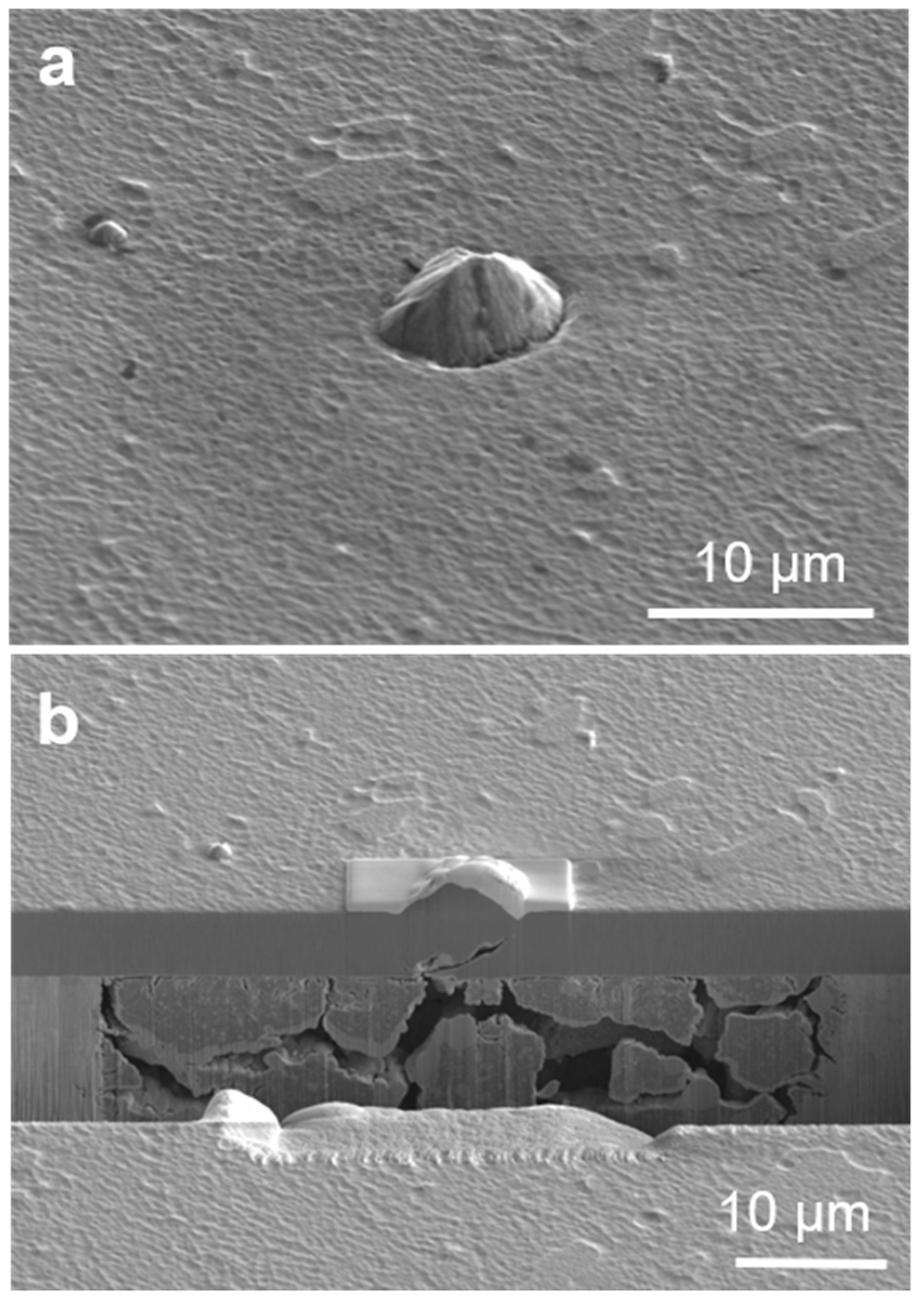
3.1.4. Pinhole Formation on Sites Where Nodular Defects Wrench out of the Coating

Another manifestation of defects is important in terms of corrosion resistance. This is a case when it comes to a detachment of the overgrown seed particles or droplets during or after deposition which leaves a crater-like dimple (Figure 6) behind. As already mentioned, this phenomenon happens because the bond between the seed particle and the nodular or flake defects with the surrounding coating matrix is poor. The whole defect or a part of it can be detached from the coating when residual stresses overcome the adhesion. The detachment probability increases with the coating thickness and the size of the nodular defect. Formation of such a hole may also be caused by external forces (such as cleaning of the coated sample by ultrasonic cavitation or wiping). If the nodular and flake defects are removed from the coating surface during the deposition process, then the crater is covered by the additional growing coating which is rather porous. If the nodular defect leaves the coating surface during the service of the coated component, a naked substrate area may be found at the bottom of these craters. If the craters, which are left by the detached nodules or flakes, are extending down to the substrate, then they offer an instant and easy access for the corrosive medium.

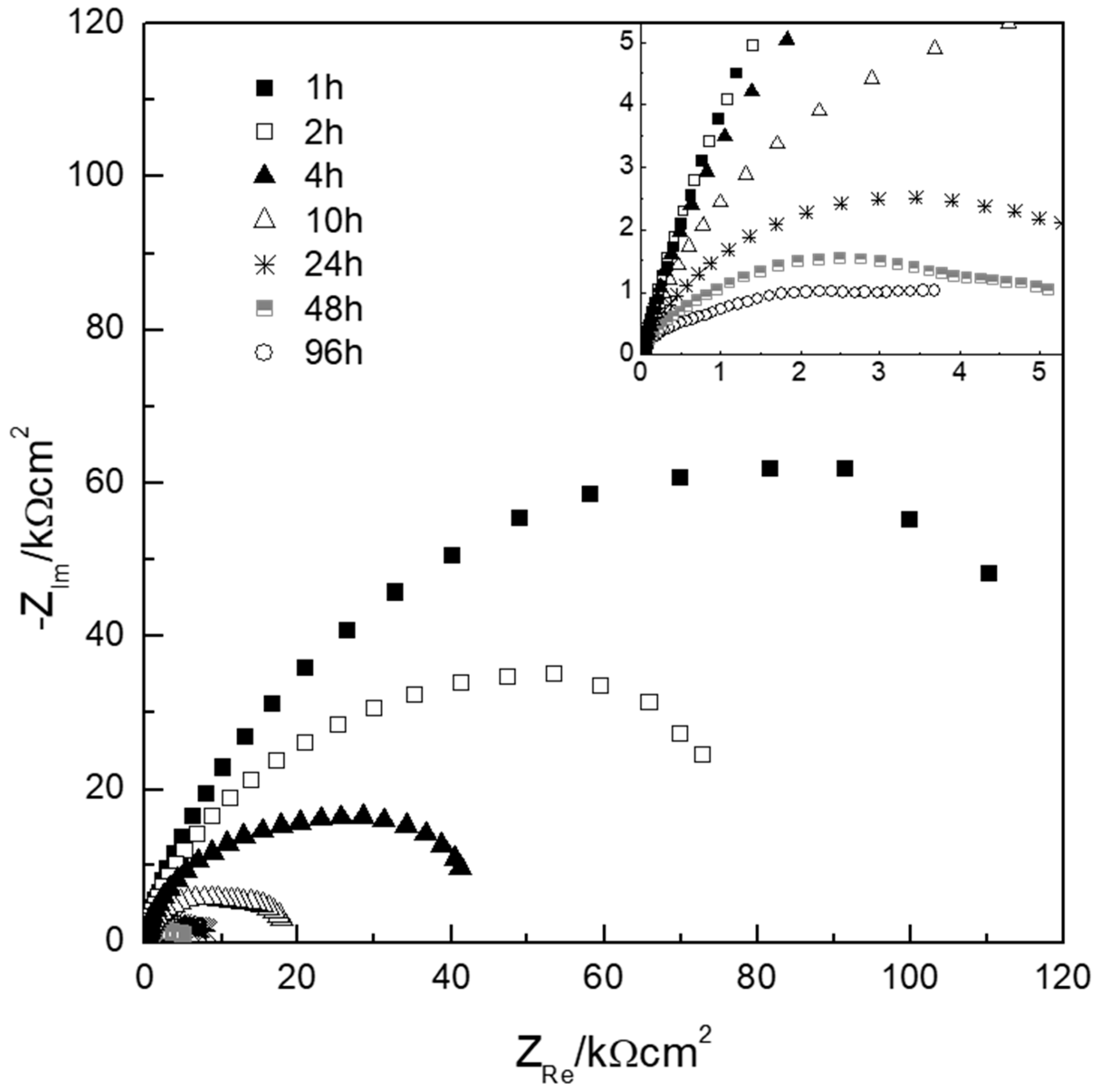
3.2. Electrochemical Impedance Measurement

A corrosion test of TiAlN deposited on D2 tool steel was performed in chloride medium using electrochemical impedance spectroscopy [32]. The exposition time was 96 h. The corrosion potential and polarization resistance (Rp) during the immersion in the corrosive medium can provide information regarding the ongoing corrosion reaction processes. Figure 7 shows the impedance response of the TiAlN/D2 coating systems in a Nyquist representation at different immersion times. Such diagrams offer some information regarding the performance of coatings deposited on less noble metal substrates. Thus, an initially high impedance (low corrosion rate) decreases with immersion time (this means that the corrosion rate increases). Higher corrosion rate can be explained by the fact that the coating defects open out, exposing more surface area of substrate to the NaCl solution. At low frequency, the interception with the real axis is ascribed to the polarization resistance (Rp, pure resistance at low frequency) at the corrosion potential. Rp resistance is the sum of resistances of coating, electrolyte in the pores, and charge–transfer (corrosion) reaction at the substrate/electrolyte interface. As the immersion time increases, the Rp values decrease for one order of magnitude, which indicates that the response becomes more conductive; indeed, with increasing time, the open voids and pinholes permit the solution to penetrate through to the steel substrate, causing localized corrosion. There are significant variations of corrosion current density, corrosion potential, and polarization resistance for nominally identical samples. This is consistent with corrosion caused by defects that are randomly distributed across the sample.

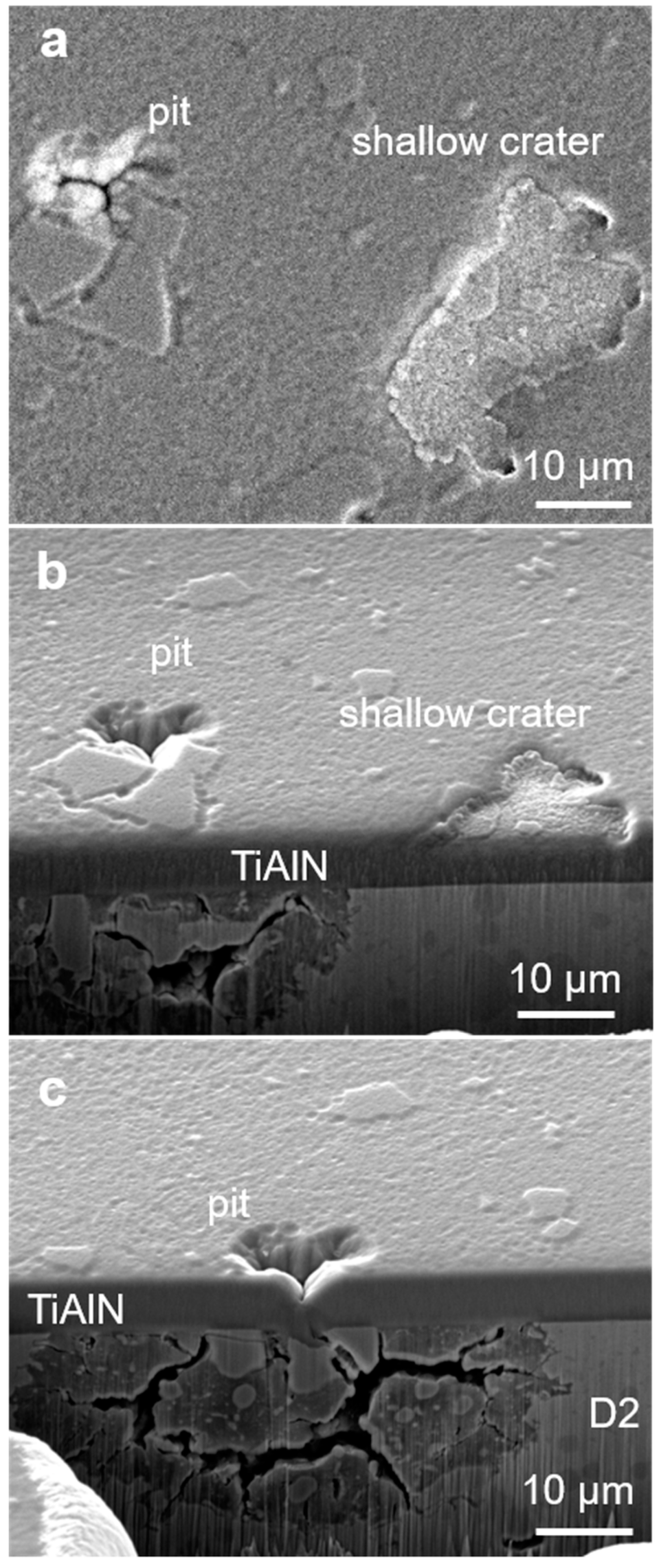
3.3. Typical Pitting Corrosion Attack at Growth Defects

The inspection of the corroded sample was carried out in an optical microscope and SEM, following the electrochemical test. The corrosion attack under the coating, where the defect had been generated, was analyzed at the cross-section, prepared by the FIB technique. The inspection by optical and SEM microscope of the corroded sample revealed that pitting corrosion occurred only at certain growth defects. The measure of pitting corrosion intensity could be the area of the circular ring with corrosion products around the growth defect. The larger the radius, the more intensive pitting corrosion has been. However, the corrosion intensity of selected growth defects is not constant during the exposure to the corrosive media. In some cases, a certain time is necessary for pit formation, while later, the corrosion initiation sites are often filled with corrosion products (sealing effect) [5,13]. Corrosion products which accumulate at the pit sites hinder the local access to the electrolyte and thus reduce the corrosion kinetics.
The consecutive serial sectioning of thin slices performed by FIB technique and imaging of cross-sections gives us the insight into the defect internal structure, while EDX map analysis enables the determination of the composition of both seed as well as corrosion products. From the FIB cross-section, we also obtained the information on the intensity of the corrosion attack under the coating where the defect had been generated. A measure of the pitting corrosion intensity at a selected pinhole can also be the volume of the substrate material which had been removed.
We found that during the electrochemical test, different local defects (pinhole, pore, and crevice) caused localized corrosion of different intensities. Even in the case of the same type of defects, the corrosion intensity was very different, depending on how the pathways around the defect toward the substrate surface were open. In the following text, some typical examples are presented. Figure 8 shows the nodular defect, which started to grow on the substrate surface on an iron-based seed particle, but no traces of corrosion were observed. It is evident that the seed has a simple shape and smooth surface, while the boundary between the nodular defect and the coating matrix is mainly closed. It is completely different in the cases of nodular defects shown in Figure 9 and Figure 10, where severe corrosion attacks occurred. Traces of corrosion products are still visible around the nodular defects, although the majority of the accumulated corrosion products were removed after the corrosion test by the sample-cleaning procedure. In the last two cases, the shape of seeds is more complex; they are composed from iron and chromium, indicating they are wear debris originating from the fixture system. In the case of severe corrosion (Figure 9 and Figure 10), a crevice between the nodule and the coating matrix can be observed. Its width is not uniform and depends on the dimension and shape of the seed particle. This is consistent with the findings of Balzer et al. that the more complex seed geometry causes a more complex shading and the boundary between the nodular defect and the coating matrix is more porous [31]. The arrow in Figure 10c indicates a crevice where EDX maps (Figure 10) show traces of oxide products and chlorine, which proves that it was a pathway for solution penetration through the void zones around the nodular defects.
Figure 11a shows another example where two defects in the TiAlN coating (pinhole, dish-like crater) were analyzed by the FIB. The right dish-like crater is much larger, but it is shallow and does not extend down to the substrate (Figure 11b). Because it is limited to the topmost part of the coating, there are no traces of corrosion at this site. On the other side, a very narrow pinhole in the coating on the left shows extensive damage in the substrate which is located underneath (Figure 11c). We can see that the site where the pinhole started is a pit at which a small piece of carbide grain was torn out, probably during mechanical pretreatment of the substrate surface. The similar type of pinhole in Figure 12a, generated on the same coated sample, caused a less intensive corrosion attack (Figure 12b) during the electrochemical test than that shown in Figure 11c, because the opening of the pinhole is evidently smaller.
The last case is the corrosion attack at a crater-like dimple formed on the site where nodular defects were detached (Figure 13). An extremely strong corrosion attack occurred at such kind of coating defect. The strength of the driving force for dissolution of steel in NaCl solution is seen from the volume of the cavity which was generated by the dissolved steel underneath the coating. Namely, all this dissolved material has been transferred through the small channels around the nodular defect.

4. Conclusions

All PVD hard coatings contain some degree of microporosity (i.e., open pores, pinholes, void zones around the nodular defects or droplets, microcracks, and pores between the columns). In this study, we confirmed the deleterious effect of through-thickness growth defects on corrosion resistance of sputter-deposited TiAlN hard coating. We performed a systematic overview of all the mechanisms that lead to the creation of such defects. There are many possible causes of such defects: pits on the substrate surface formed during its pretreatment, different nonmetallic inclusions in the tool steels, foreign and flake particles which arrived on the substrate surface before the deposition process, localized delamination of coating, and microcracks. To prove the existence of such defects in the hard coating, we used the FIB technique. After the corrosion test performed in chlorine solution using electrochemical impedance spectroscopy, selected growth defects were analyzed by the SEM/FIB. Using FIB, we made serial cross-sections through individual selected defects in order to obtain an insight into the corrosion process at different kinds of growth defects.
We confirmed that pitting corrosion is closely related to the through-thickness growth defects. We found that the intensity of the pitting corrosion of different through-thickness growth defects is very different. On the same sample, exposed to corrosive medium, the effects of pitting corrosion at the sites of some defects are hardly visible, while at others, catastrophic corrosion attacks occurred. It all depends on how very open the path to the substrate is. We also found that in the case of nodular defects, the intensity of corrosion depends on the shape of the seed. The shape of the seed determines whether the crevice down to the substrate will occur or not.

Author Contributions

Conceptualization, Manuscript Writing, P.P.; FIB Analysis of Growth Defects and Corroded Samples, A.D.; SEM Analysis of Defects, P.G.; Manuscript Review and Editing, M.Č. and M.P.; FIB analysis of Nonmetallic Inclusions, T.B.; Electrochemical Impedance Test, D.K.M.

Funding

This work was funded by the Slovenian Research Agency (program P2-0082). We also acknowledge funding from the European Regional Development Funds (CENN Nanocenter, OP13.1.1.2.02.006).

Acknowledgments

The authors wish to commemorate Darja Kek Merl who passed away two years ago.

Conflicts of Interest

The authors declare no conflict of interest.

References

  1. Tietems, R. Large-scale industrial coating applications and systems comprehensive materials processing. Elsevier 2014, 4, 519–561. [Google Scholar]
  2. Haubner, R.; Lessiak, M.; Pitonak, R.; Köpf, A. Weissenbacher. Int. J. Refract. Met. Hard Mater. 2017, 62, 210–218. [Google Scholar] [CrossRef]
  3. D’Avico, L.; Beltrami, R.; Lecis, N.; Trasatti, S.P. Corrosion behavior and surface properties of PVD coatings for mold technology applications. Coatings 2019, 9, 7. [Google Scholar] [CrossRef]
  4. Jehn, H.A. Improvement of the corrosion resistance of PVD hard coating–substrate systems. Surf. Coat. Technol. 2000, 125, 212–217. [Google Scholar] [CrossRef]
  5. Fenker, M.; Balzer, M.; Kappl, H. Corrosion protection with hard coatings on steel: Past approaches and current research efforts. Surf. Coat. Technol. 2014, 257, 182–205. [Google Scholar] [CrossRef]
  6. Ahn, S.; Lee, J.; Kim, J.; Han, J. Localized corrosion mechanisms of the multilayered coatings related to growth defects. Surf. Coat. Technol. 2004, 177, 638–644. [Google Scholar] [CrossRef]
  7. Balzer, M. Identification of the growth defects responsible for pitting corrosion on sputter-coated steel samples by Large Area High Resolution mapping. Thin Solid Films 2015, 581, 99–106. [Google Scholar] [CrossRef]
  8. Lewis, D.B.; Creasey, S.J.; Wüstefeld, C.; Ehiasarian, A.P.; Hovsepian, P.E. The role of the growth defects on the corrosion resistance of CrN/NbN superlattice coatings deposited at low temperatures. Thin Solid Films 2006, 503, 143–148. [Google Scholar] [CrossRef]
  9. Korhonen, A.S. Corrosion of thin hard PVD coatings. Vacuum 1994, 45, 1031–1034. [Google Scholar] [CrossRef]
  10. Merl, D.K.; Panjan, P.; Panjan, M.; Čekada, M. The role of surface defects density on corrosion resistance of pvd hard coatings. Plasma Process. Polym. 2007, 4, 5613–5617. [Google Scholar] [CrossRef]
  11. Penttinen, I.M.; Korhonen, A.S.; Harju, E.; Turkia, M.A.; Forsen, O.; Ristolainen, O.E. Comparison of the corrosion resistance of TiN and (Ti,Al)N coatings. Surf. Coat. Technol. 1992, 50, 161–168. [Google Scholar] [CrossRef]
  12. Wang, H.W.; Stack, M.M.; Lyon, S.B.; Hovsepian, P.; Münz, W.-D. The corrosion behaviour of macroparticle defects in arc bond-sputtered CrN/NbN superlattice coatings. Surf. Coat. Technol. 2000, 126, 279–287. [Google Scholar] [CrossRef]
  13. Hoche, H.; Pusch, C.; Oechsner, M. Establishing PVD-coatings for the corrosion protection of mild steel substrates for complex tribological and corrosive stresses. Surf. Coat. Technol. 2018, in press. [Google Scholar] [CrossRef]
  14. Mattox, D.M. Surface effects on the growth, adhesion and properties of reactively deposited hard coatings. Surf. Coat. Technol. 1996, 81, 8–16. [Google Scholar] [CrossRef]
  15. Liu, C.; Leyland, A.; Bi, Q.; Matthews, A. Corrosion resistance of multilayered plasma-assisted physical vapour deposition TiN and CrN coatings. Surf. Coat. Technol. 2001, 141, 164–173. [Google Scholar]
  16. Fenker, M.; Balzer, M.; Kappl, H. Corrosion behaviour of decorative and wear resistant coatings on steel deposited by reactive magnetron sputtering–Tests and improvements. Thin Solid Films 2006, 515, 27–32. [Google Scholar] [CrossRef]
  17. Härkönen, E.; Kolev, J.; Díaz, B.; Swiatowska, J.; Maurice, V.; Seyeux, A.; Marcus, P.; Fenker, M.; Toth, L.; Radnoczi, G.; et al. Sealing of hard CrN and DLC coatings with atomic layer deposition. ACS Appl. Mater. Interfaces 2014, 6, 1893–1901. [Google Scholar] [CrossRef]
  18. Wan, Z.; Zhang, T.F.; Ding, J.C.; Kim, C.-M.; Park, S.-W.; Yang, Y.; Kim, K.-H.; Kwon, S.-H. Enhanced corrosion resistance of pvd-crn coatings by ald sealing layers. Nanoscale Res. Lett. 2017, 12, 248. [Google Scholar] [CrossRef]
  19. Heyn, A.; Mueller, T.; Balzer, M.; Kappl, H.; FenkeI, M. Corrosion protection mechanisms of TiMgN hard coatings on steel. IOP Conf. Ser. Mater. Sci. Eng. 2018, 373, 012009. [Google Scholar] [CrossRef]
  20. Barshilia, H.C.; Prakash, M.S.; Poojari, A.; Rajam, K.S. Corrosion behavior of nanolayered TiN/NbN multilayer coatings prepared by reactive direct current magnetron sputtering process. Thin Solid Films 2004, 460, 133–142. [Google Scholar] [CrossRef]
  21. Herranen, M.; Wiklund, U.; Carlsson, J.-O.; Hogmark, S. Corrosion behaviour of Ti/TiN multilayer coated tool steel. Surf. Coat. Technol. 1998, 99, 191–196. [Google Scholar] [CrossRef]
  22. Mendibide, C.; Steyer, P.; Millet, J.-P. Formation of a semiconductive surface film on nanomultilayered TiN/CrN coatings and its correlation with corrosion protection of steel. Surf. Coat. Technol. 2005, 200, 109–112. [Google Scholar] [CrossRef]
  23. Abdeen, D.H.; el Hachach, M.; Koc, M.; Atieh, M.A. A review on the corrosion behaviour of nanocoatings on metallic substrates. Materials 2019, 12, 210. [Google Scholar] [CrossRef]
  24. Fenker, M.; Balzer, M.; Jehn, H.A.; Kappl, H.; Lee, J.J.; Lee, K.H.; Park, H.S. Improvement of the corrosion resistance of hard wear resistant coatings by intermediate plasma etching or multilayered structure. Surf. Coat. Technol. 2002, 150, 101–106. [Google Scholar] [CrossRef]
  25. Abusuilik, S.B.; Inoue, K. Effects of intermediate surface treatments on corrosion resistance of cathodic arc PVD hard coatings. Surf. Coat. Technol. 2013, 237, 421–428. [Google Scholar] [CrossRef]
  26. Fenker, M.; Kappl, H.; Petrikowski, K.; Bretzler, R. Pulsed power magnetron sputtering of a niobium target in reactive oxygen and/or nitrogen atmosphere. Surf. Coat. Technol. 2005, 200, 1356. [Google Scholar] [CrossRef]
  27. Reinhard, C.; Ehiasarian, A.P.; Hovsepian, P.E. CrN/NbN superlattice structured coatings with enhanced corrosion resistance achieved by high power impulse magnetron sputtering interface pre-treatment. Thin Solid Films 2007, 515, 3685–3692. [Google Scholar] [CrossRef]
  28. Panjan, P.; Čekada, M.; Panjan, M.; Kek-Merl, D. Growth defects in PVD hard coatings. Vacuum 2010, 84, 209–214. [Google Scholar] [CrossRef]
  29. Panjan, P.; Merl, D.K.; Zupanič, F.; Čekada, M.; Panjan, M. SEM study of defects in PVD hard coatings using focused ion beam milling. Surf. Coat. Technol. 2008, 202, 2302–2305. [Google Scholar] [CrossRef]
  30. Harlin, P.; Bexell, U.; Olsson, M. Influence of surface topography of arc-deposited TiN and sputter-deposited WC/C coatings on the initial material transfer tendency and friction characteristics under dry sliding contact conditions. Surf. Coat. Technol. 2009, 203, 1748–1755. [Google Scholar] [CrossRef]
  31. Balzer, M.; Fenker, M.; Kappl, H.; Muller, T.; Heyn, A.; Heiss, A.; Richter, A. Corrosion protection of steel substrates by magnetron sputtered TiMgN hard coatings: Structure, mechanical properties and growth defect related salt spray test results. Surf. Coat. Technol. 2018, 349, 82–92. [Google Scholar] [CrossRef]
  32. Merl, D.K.; Panjan, P.; Čekada, M.; Maček, M. The corrosion behavior of Cr-(C,N) PVD hard coatings deposited on various substrates. Electrochim. Acta 2004, 49, 1527–1533. [Google Scholar] [CrossRef]
Figure 1. Pit on the D2 tool steel substrate surface at the site where a carbide grain was torn out from the surface of the D2 tool steel during the polishing process (a) and the same substrate surface area after deposition of a hard coating (b). Close to the pinhole, a nodular defect was also formed.
Coatings 09 00511 g001
Figure 2. Planar SEM view of a pinhole in the Al2O3/TiAlN hard coating deposited on ASP30 tool steel (a) and fracture cross-sectional SEM image of selected pinholes which appeared at shallow craters formed during ion etching at (W, Mo)C carbide in ASP30 tool steel substrate (b).
Coatings 09 00511 g002
Figure 3. SEM images of the same MnS inclusion in the D2 substrate: (a) after polishing; (b) after ion etching; (c) after deposition of a hard coating. Above the MnS inclusion, a pit can be also observed on the polished substrate. In a similar way to the example in Figure 1, it caused the formation of the pinhole (c).
Coatings 09 00511 g003aCoatings 09 00511 g003b
Figure 4. SEM images of the same Al2O3 inclusion in the D2 substrate after ion etching (a) and after deposition of hard coating (b).
Coatings 09 00511 g004
Figure 5. SEM planar view (a) and FIB cross-sectional image of a nodular defect (b) in the TiAlN hard coating sputter deposited on D2 steel.
Coatings 09 00511 g005
Figure 6. Fracture cross-sectional SEM image of the crater-like dimple which was left by the detachment of a nodular defect (a) and a nodular defect which has remained in the coating (b).
Coatings 09 00511 g006
Figure 7. The impedance response of the TiAlN/D2 coating systems in a Nyquist representation at different immersion times.
Coatings 09 00511 g007
Figure 8. SEM top view (a) and FIB image (b) of a nodular defect where no pitting corrosion was observed. The nodular defect is intact and no crevices are visible at the boundary between the defect and the coating matrix.
Coatings 09 00511 g008
Figure 9. SEM top view (a) and FIB image (b) of a nodular defect where intensive pitting corrosion occurred.
Coatings 09 00511 g009
Figure 10. SEM top view (a) and FIB images of nodular defects and corresponding EDX maps where intensive pitting corrosion occurred (b,c).
Coatings 09 00511 g010
Figure 11. SEM top view of a pinhole and shallow crater (a) and FIB section across the crater (b) and pinhole center (c).
Coatings 09 00511 g011
Figure 12. SEM top view (a) and FIB images of pinhole (b) where weak pitting corrosion occurs.
Coatings 09 00511 g012
Figure 13. SEM top view of crater-like dimple (a) in sputter deposited D2 hard coating where extremly intensive pitting corrosion occured (b).
Coatings 09 00511 g013

