Review

Literature Review on Fretting Wear and Contact Mechanics of Tribological Coatings

1
S & V Lab, Department of Engineering Mechanics, Xi’an Jiaotong University, Xi’an 710049, China
2
Biomechanics Laboratory, College of Sport Science, Sungkyunkwan University, Suwon 440-746, Korea
3
IMT Mines Saint-Étienne, Centre CIS, INSERM, SainBioSE, Université de Lyon, F-42023 Saint-Étienne, France
4
Department of Mechanical Engineering, Incheon National University, 119 Academy-ro, Yeonsu-gu, Incheon 22012, Korea
5
School of Aerospace and Mechanical Engineering, Korea Aerospace University, 76 Hanggongdaehak-ro, Deogyang-gu, Goyang-si, Gyeonggi-do 412-791, Korea
*
Author to whom correspondence should be addressed.
Coatings 2019, 9(8), 501; https://doi.org/10.3390/coatings9080501
Submission received: 13 June 2019 / Revised: 23 July 2019 / Accepted: 6 August 2019 / Published: 7 August 2019
(This article belongs to the Special Issue Advanced Coatings for Resisting Fretting Damage)

Abstract

:
This article reviews fretting wear damage in industries and in the contact mechanics of coated systems. Micro-slip motion resulting in fretting damage is discussed along with major experimental factors. The experimental factors, including normal force, relative displacement, frequency and medium influence are directly compared. Industrial solutions to reduce fretting damages are then discussed. The contact mechanics of a coated system are reviewed to quantify stress states in a coating layer and the substrate. Finally, a literature review on simulation for fretting is carried out. This review study provides useful methods and practical solutions to minimize fretting wear damage.

1. Introduction

A reciprocal relative displacement is often observed at the contact surface between two mating mechanical components. If a reciprocal relative displacement is so small that slip partially occurs, cracking is mainly observed near the edges of the contact. Cracks grow with respect to the number of cycles, and eventually bring about the failure of a material. This is known as fretting fatigue [1,2]. When the magnitude of a relative displacement is sufficiently large to induce a gross slip between mating surfaces, the removal of material in a contact zone dominantly occurs. Some of the worn particles are ejected but others are entrapped within the contact zone. This phenomenon is referred to as fretting wear [3,4]. A mixed stick-slip regime is observed between a partial slip and a gross slip regime as shown in Figure 1 [5]. If corrosion damage occurs at the asperities of a contact surface under load and in the presence of a relative displacement, this phenomenon is known as fretting corrosion [6]. If the relative displacement is greater than the contact size, sliding wear occurs at the contact. The slip regime is determined with parameters such as contact load and displacement amplitude as presented in Figure 1. Along with the parameters, frequency (reciprocation per second) and initial surface roughness could affect a slip regime [7,8]. For example, in the case of TiN coating, the increase on frequency led to the transition from a gross slip to a mixed regime. The initial surface roughness of low carbon alloy was found to have an influence on actual sliding distance and the slip regime in which a fretting test is performed [8].
Fretting damage is observed in various industries [9,10,11,12]. Particularly, fretting wear is one of the critical issues in aerospace, biomedical, automotive, and nuclear components. The components include a blade-disc interface in an aero-engine, a stem-cement interface in total hip prosthesis, a plug-jack interface in an automotive electric connector, and a fuel rod-supporter interface in a nuclear reactor. In detail, at the blade-disc interface in an aero-engine, engine vibration and centrifugal force lead to fretting fatigue and fretting wear [9]. At the stem-cement and any metal/materials contact interface in total hip prosthesis, human gait brings about progressive contact degradation [10]. In an automotive electric connector, auto-engine vibration leads to fretting wear damage [11]. Meanwhile, at a fuel rod-supporter interface in a nuclear reactor, fretting wear occurs due to flowing water [12]. As presented above, fretting wear damage is observed in various components, though the working environment is different. Thus, at the design step of these components, fretting wear is critically considered.
In order to minimize fretting wear damage in these components, various solutions are taken into account. Possible solutions include the development of new substrate materials, deposition of low friction coatings on the substrate, selection of optimal contact geometry, and substrate surface treatment. Selection of an adequate solution is dependent upon the working environment and contact situation. Nevertheless, little is found in the way of direct comparison of practical solutions in industries. A review of practical solutions provides a clue in solving fretting damage and in designing mechanical components.
Fretting is a contact phenomenon between two mating bodies. It is important to understand the contact theoretically. Particularly, the contact in a coated system needs to be analyzed. The contact between coated bodies leads to complex stress states within coating layers and bodies [1]. The stress state is affected by the friction coefficient, the type of contact (complete or incomplete), and the elastic moduli of a coating, the substrate, and an indenter. In practices, various coated systems are designed, including multiple coating layers. Thus, coated contact problems can be approximately classified into three groups: single layer, multi-layer, and a functionally graded material layer. In this paper, the contact mechanics of the groups is reviewed. In order to predict the fretting lifetime of a coated system, the contact damage that has arisen from fretting needs to be simulated. Friction and wear laws in tribology are often used for simulating fretting.
The objectives of this study are (i) to compare fretting wear conditions observed in the aerospace, biomedical, automotive and nuclear industries; (ii) to support recent developments on fretting wear and contact mechanics; and (iii) to provide a method to simulate fretting wear. The experimental conditions are identified through a literature review, and experimental parameters observed in industries are directly compared. Recent solutions to minimize fretting wear damage are then discussed. Development in the contact mechanics of a coated system is described. Fretting wear is a complex contact phenomenon. Thus, the difficulty in simulating fretting wear persists. In particular, it is difficult to simulate the fretting wear of a coated system, since various factors, including surface roughness, greatly affect the fretting wear process and the lifetime of a coated system. Therefore, it might be useful to understand fretting and friction at the nano-scale. In this paper, nano-scale simulation was also reviewed to understand fretting and friction problems.

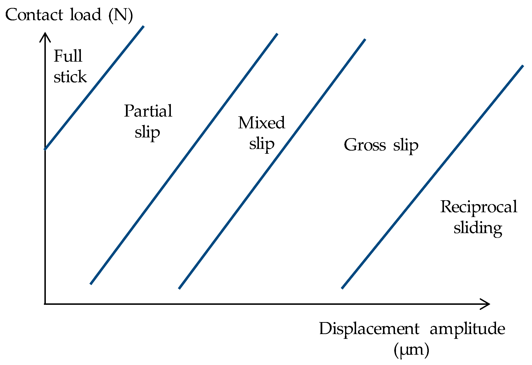
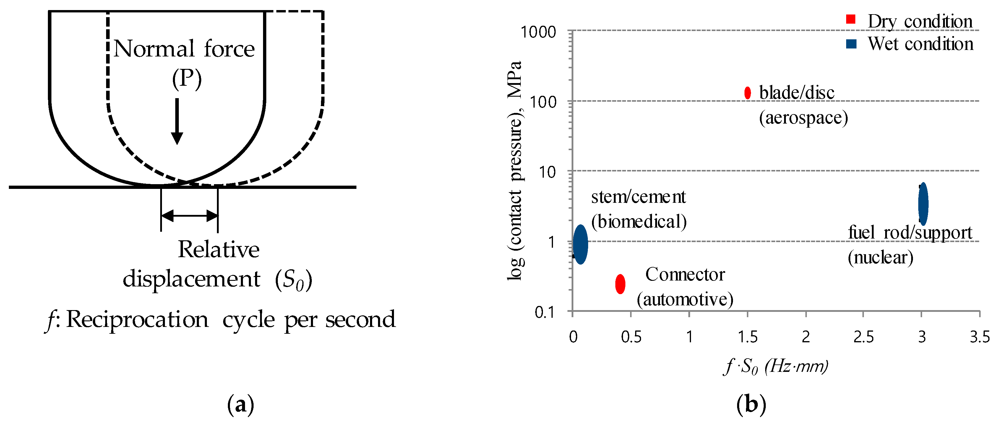
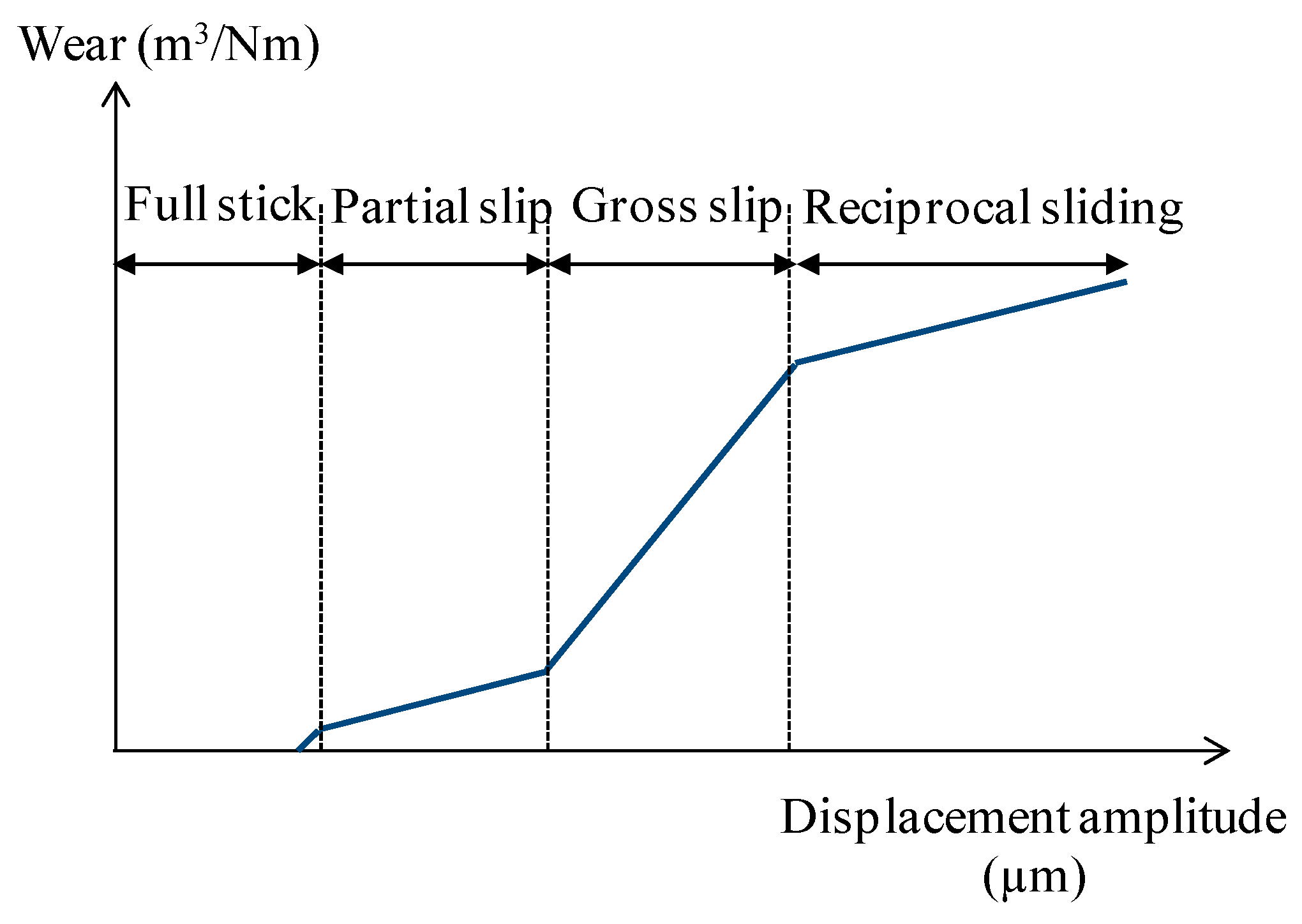
2. Experimental Fretting Conditions Found in Industries

Fretting wear damage is determined according to experimental conditions. Typical experimental conditions include frequency, medium, contact pressure (or normal force), and the relative displacement between two contacting bodies. For the purpose of evaluating the fretting damage of a mechanical component, these factors (i.e., frequency, contact pressure, and relative displacement) are pre-described and then fretting tests are conducted.
Figure 2 shows experimental fretting conditions found in different industries. At the blade-disc interface in an aero-engine, a contact pressure of 130 MPa, a frequency of 2.5 Hz, and a relative displacement of 0.6 mm are typically considered; the imposed frequency is based on low-frequency high-amplitude cycles resulting from taking-off and landing of an airplane [9,13]. At the stem-cement interface in a hip implant (total hip prosthesis), a contact pressure of 0.6–20 MPa, a frequency of 1 Hz and a displacement of 0.02–0.06 mm are taken into account [14]. At automotive electric connectors, a frequency of 8 Hz, an imposed displacement of 0.05 mm, and a contact pressure of about 0.2 MPa are assumed for a fretting wear test [15,16,17]. At a fuel rod-support interface in a nuclear reaction, a contact pressure of 2–6 MPa, a frequency of 30 Hz, and a displacement of 0.1 mm are known to be generated [13,18]. This frequency is relatively higher than those found in aerospace, automotive, and biomedical components. Meanwhile, high contact pressure is observed in aerospace components. Human liquid and water exist at the stem-cement (metal/counter materials) interface and at the fuel-support interface, respectively. These liquids affect fretting wear damage. Particularly, human body liquid gives rise to corrosion as well as wear of the contact surface between the stem and the cement in a hip implant.

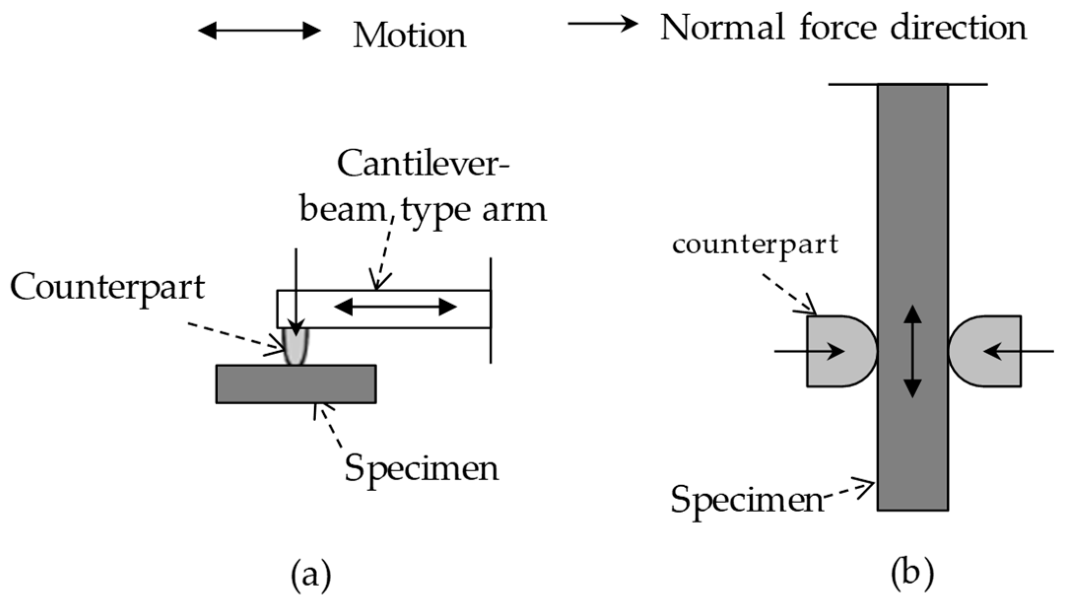
3. Experimental Methods and Evaluation Techniques

For fretting wear testing, two typical types are used as shown in Figure 3. One type is a cantilever-beam type test rig and the other is an in-line testing rig. A conventional wear testing arrangement is modified for a cantilever-beam type test rig. A reciprocal relative displacement is made to induce gross slip at the contact surface between a counterpart and a specimen. During a fretting wear test, maintaining high contact tractions and gross slip conditions is critically important. In a cantilever-beam type tester, it might be difficult to impose the high contact load found in aerospace components; a frictional force could bring about a moment of a counterpart. The arm is required to maintain sufficient rigidity. Thus, an in-line fretting wear testing arrangement is found to be more adequate for a high contact load. In an in-line arrangement, two counterparts are needed for a single fretting wear test. And, it is necessary to induce the same contact load to the contact surfaces between counterparts and the specimen. In both types, the frictional force and the relative displacement between a counterpart and a specimen are continuously measured during a fretting test.
There exist two typical methods to evaluate fretting wear damage. One is the measurement of wear volume on a worn surface after a fretting test. Optical profilometry, a confocal microscope, and a 3D mechanical profilometer are used for measuring wear volume [19]. The indentation technique was merely used for determining remnant coating thickness on a coated system. In order to determine wear rate, it is necessary to conduct a series of fretting wear tests and to interrupt the tests at various fretting cycles. In the case of a coated system, variance of initial coating thickness should be small among samples. In a corrosive environment, open circuit potential (OCP) is also monitored [20].
The other method to evaluate fretting wear damage is measurement of the kinetic friction coefficient. The coefficient of kinetic friction is widely used for evaluating fretting damage. The friction coefficient is defined as the ratio of the maximum tangential force to normal force at a contact surface, thereby load needs to be measured. A load-cell is attached on a test rig. The friction coefficient varies according to surface treatment, lubricant, surface roughness, and material. The method with the friction coefficient is often limited to a coated system, since the friction coefficient at a coating layer-to-substrate contact is somewhat different than that found at the substrate-to-substrate contact. Relative displacement is measured in the course of a fretting wear test. This displacement information is used to produce a fretting loop [21,22]; a single fretting loop is produced after each fretting cycle. A fretting loop is used for identifying a slip regime. As described above, a fretting wear test should be conducted in a gross slip regime.
For a fretting test with a coated system, it is necessary to determine when a test is terminated. Typically, a fretting test with a coating is interrupted when the coefficient of kinetic friction becomes a value similar to that found in a dry test without a coating. Figure 4 shows an example of friction coefficient evolutions of a coated system and of an uncoated system. An AISI 52100 steel ball was slid over the substrate of a high strength steel plate with an imposed displacement of 0.3 mm [23]. The friction coefficient came to steady after the running-in period. At the steady state sliding, the friction coefficient was about 0.55. The value of the friction coefficient was used for determining the termination of a fretting wear test with a coating. When the test is terminated, the number of cycle can be defined as the fretting lifetime of a coating.
It is necessary to confirm that a fretting test is completed in a partial slip regime for fretting fatigue and in a gross slip regime for fretting wear (Figure 5). Transition between slip regimes is identified with various parameters such as energy ratio, slip index and slip ratio [21,22]. Table 1 shows the parameters used for identification of slip regimes. The parameters can be calculated with a fretting loop as shown in Figure 6.
The term energy ratio is defined as the ratio of dissipated energy (the area within a fretting loop) to total energy. If the energy ratio remains above 0.2 during a fretting test, it is known that the test is completed in a gross slip regime [21].
For computing the energy ratio, it is necessary to operate a process to measure the area within a fretting loop. The Gauss-green function may be used for computing the area within a fretting loop. Meanwhile, the term slip index (δ) is determined with a tangential force, a normal force, total displacement, and actual sliding distance [22]; it is found that a gross slip regime is characterized by 0.8 < δ < 10, and a partial slip regime by 0.5 < δ < 0.6. The stiffness in a fretting loop has an influence on slip index. Thus, actual calculation of the stiffness on a fretting loop is needed. The slip ratio is defined as the actual sliding distance (Sd) divided by total displacement (St). The actual sliding distance is determined when a tangential force is equal to zero on a fretting loop. The slip ratio is also useful for identifying a sliding condition. It was identified that the transition between partial slip and gross slip regimes was 0.26 or 0.17 [21,22]. The transition between gross slip and reciprocal sliding was found to be about 0.95 [22].
Figure 7a shows an example of the change of the energy ratio of a dry film lubricant with respect to the number of cycles [24]. The initial fretting test started within a gross slip regime. The energy ratio was changed with respect to the number of fretting cycles. After 8000 cycles, the energy ratio remained below 0.2, indicating that the test was conducted within a partial slip regime. Figure 7b shows the example of the slip index for a dry film lubricant [25]. The slip index remained below 0.6 during a test. Figure 7c shows the slip ratio of a dry film lubricant according to the number of fretting cycles [25]. A slip ratio of 0.26 was found in the transition from a gross slip and a partial slip regime. During a fretting test, it was identified that a slip regime was changed. In order to evaluate fretting wear, it is thus necessary to monitor a test and identify a slip regime.

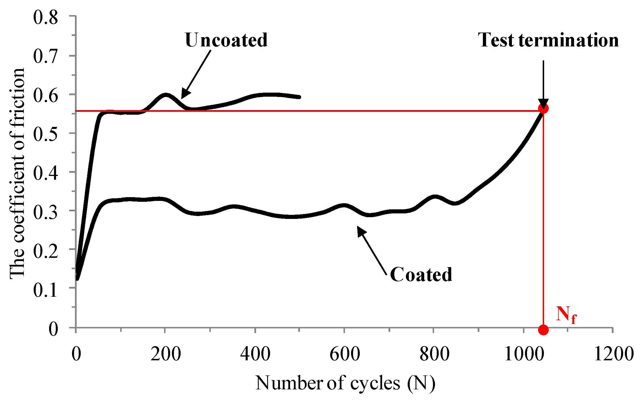
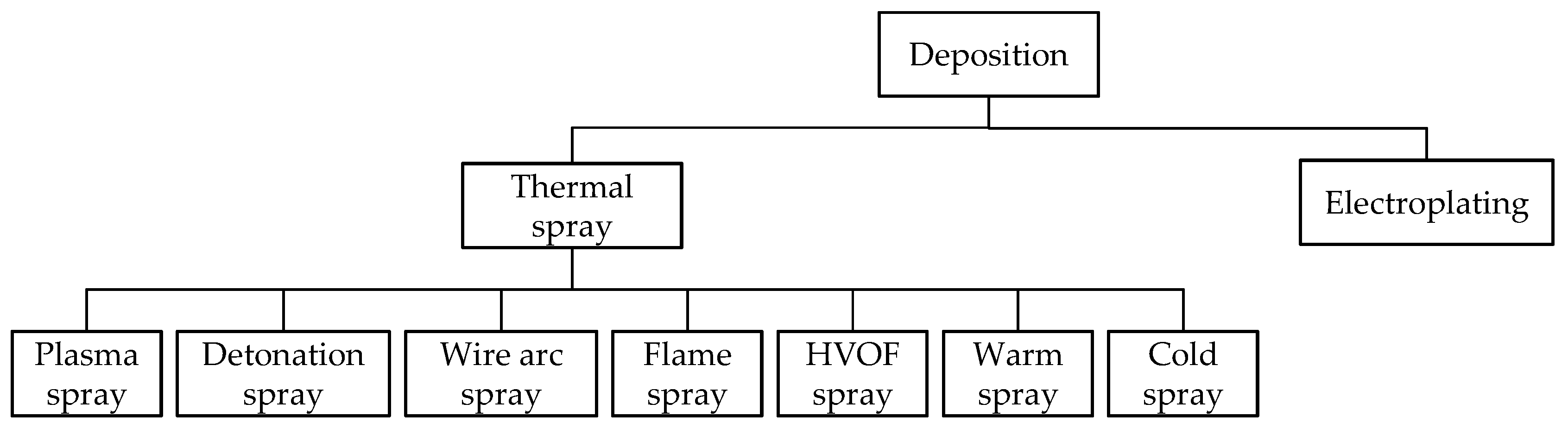
4. Recent Solutions to Resist Fretting Wear Damage

Recent solutions to reduce fretting wear damage somewhat vary with respect to each industry. But, a low friction coating is the primary choice to reduce fretting damage in most industries. Figure 8 shows the sort of deposition of a low friction coating to reduce fretting wear damage. A thermal spray technique is known as the coating deposition process that heated coating materials are sprayed on a target surface. This technique enables high deposition rate compared to other techniques. Thus, this is used for depositing a coating on aerospace or nuclear components. The electroplating technique is a process whereby a thin coherent metal coating is formed on an electrode by using an electric current [17,26]. The nickel, copper, and gold used in the process improve the corrosion resistance of a surface. Thus, this deposition technique is mainly considered for automotive components.
Table 2 shows practical solutions to reduce fretting damage in industries. Solutions were found to vary because each experimental condition is different. For the aerospace blade root-disc interface, flat-and-round contact is considered as the optimal contact. The radius of the round is determined to minimize contact stress. For biomedical components, plane-to-plane (with small radius at edges) contact is taken into account. At the fuel rod-support interface, a cylinder comes in contact with the cylindrical support located perpendicular to the mating cylinder axis. Contact geometries at the fuel rod-support interface continue to be studied. As a support, a spring and a dimple are used. These components play a role in reducing the vibration of a fuel rod and contact pressure.
In order to reduce fretting damage at the blade-disc interface, a thermally sprayed double layer coating is deposited on the surface of Ti-6Al-4V alloy [25,26]. That is, the coating is applied onto the surfaces of a blade root and a disc. The coating consists of an interlayer containing Cu, Ni, and In, and a top layer with MoS2 (Figure 9).
Other coatings such as Ni-MoS2 and CoCrAlY-MoS2 also demonstrated anti-fretting performance [27,28]. The interlayer presented in Figure 9 was changed to Ni or CoCrAlY. Titanium alloy (Ti-6Al-4V) is currently used as a blade material. In addition, Surface treatments such as shot peening, grit blasting, and laser shot peening are considered for Ti-6Al-4V alloy. It was demonstrated that shot peening did not improve fretting wear performance [29]. A mechano-chemical coating deposition was conducted on Ti-6Al-4V aerospace alloy [9]. A specially designed vibratory mill was used to produce kinds of MoS2 and carbon-based coatings. Some coatings demonstrated good anti-fretting properties under the condition similar to those found in the interface between a blade root and a disc. The coatings developed are shown in Appendix A.
In the biomedical field, Ti-6Al-4V is used as the stem material. In order to fix this metal on bone material, hydroxyapatite (HA) is deposited on titanium alloy due to its good biocompatibility. Alumina is the material of the head and cup in total hip prosthesis. To increase fracture toughness, a zirconia toughened alumina (ZTA) composite has been developed as an alternative material [30,31]. In addition, polishing is performed on the surface to reduce surface roughness up to 0.05 um.
In a nuclear field, fretting damage is reduced by introducing a low friction coating and by adapting the new contact geometry between a spring and a dimple [12,18]. TiN coating was primarily proposed to reduce fretting wear damage. In automotive electric connectors, a connector made of brass is electroplated with acid gold or tin to reduce electric contact resistance and to improve anti-fretting performance [11]. The coatings described above might allow engineers and scientists to seek possible solutions quickly.

5. Contact Mechanics of Coated Systems

Contact between coated bodies gives rise to complex stress states in the coating layers and substrates, affected by the elastic properties of the coating, substrate and indenter, the coefficient of friction, the type of contact (complete or incomplete), and the extent of contact in comparison with the coating thickness. To satisfy a variety of applications, different coating systems are designed. According to the coating layer number, the coated contact problems can be roughly classified into three groups: coated systems with (1) single layer, (2) multi-layer, and (3) functionally graded material layer (FGM), as shown in Figure 10. This actually reflects the development history of coatings applied in contact systems. The contact mechanics of the three groups can be simply reviewed, respectively, as follows:

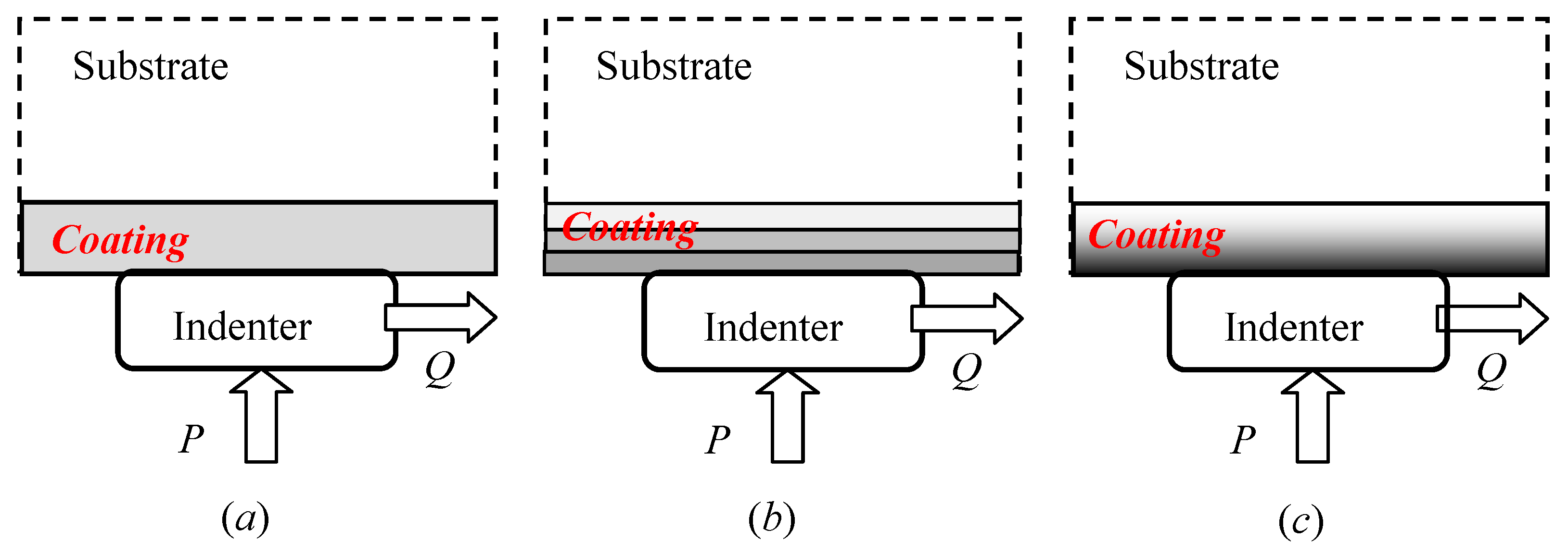
5.1. Single-Layer Coated Contacts

Figure 11a presents a frictional contact problem of a single-layer bonded to a homogeneous substrate, where the layer is indented by an indenter, and the materials of the substrate, coating and indenter are different. This is the most common coated contact problem. It has been extensively investigated for various load conditions and boundary conditions [32,33,34,35,36,37,38,39,40,41,42]. Since this is a typical elastic problem with given boundary values, except the Finite Element Method (FEM), the methods in literature for solving it can be roughly summarized in a standard procedure as: by applying Fourier transform to the governing boundary value problem, analytic expressions for the stresses and displacements induced by the application of line forces acting both normally and tangentially at the origin are derived. The superposition principle is then used to generalize these expressions to the case of distributed normal and tangential tractions acting on the solid surface, (this approach is called the Green’s function method). With other additional conditions, the contact problem can be specifically formulated. If the distributed normal and tangential tractions are separate, a pair of coupled singular integral equations can be further derived [40]:
{ 1 A g x ( x ) x = β 1 p ( x ) + 1 π K 1 ( x , t ) p ( t ) d t + β 2 π q ( t ) x t d t + 1 π K 2 ( x , t ) q ( t ) d t 1 A g y ( x ) x = β 3 q ( x ) + 1 π K 3 ( x , t ) q ( t ) d t + β 4 π p ( t ) x t d t + 1 π K 4 ( x , t ) p ( t ) d t
where g x ( x ) and g y ( x ) are gap functions in x- and y- directions, respectively. A , β i ( i = 1 , 2 , 3 , 4 ) are material related constants. K i ( x , t ) , ( i = 1 , 2 , 3 , 4 ) are related regular functions. p ( x ) and q ( x ) are normal traction and tangential traction to be solved. This form can be treated as the generalized governing equations for coated contact problems. When a partial slip occurs in coated contacts, Equation (1) may play an important role in the simulation [43].
If the coating material is identical to the one of substrate, Equation (1) will automatically degenerate to the uncoated contact governing equations [43,44]. In the literature, fully sliding contacts are extensively investigated, which can be derived from Equation (1) by adopting Coulomb’s friction law as
1 A g y ( x ) x = β 3 f p ( x ) + 1 π [ β 4 x t + f K 3 ( x , t ) + K 4 ( x , t ) ] p ( t ) d t
where f is Coulomb’s friction coefficient. It can be put in the standard Fredholm singular integral equation of the second kind [34,35,36,37,43,45]:
a p ( x ) + b π p ( t ) x t d t + c π K ( x , t ) p ( t ) d t = φ ( x )
Clearly, it is very difficult to develop an approach to find the analytical solution to Equation (3). Efficient numerical methods to solving Equation (3) (i.e., sliding contact problems) have been studied [40,41,45,46,47]. Explicit formulae for the Gauss–Jacobi numerical integration scheme appropriate for the singular integral equations have been derived. From the Gauss–Jacobi quadrature, the existing Gauss–Chebyshev quadrature formulas can be easily derived for frictionless contact problems.
The apparent advantage of singular integral equation approach and its Gauss–Jacobi numerical integration scheme is its ability to correctly capture the singular or regular behavior of the tractions at the edge of the region of sliding contacts.
As shown in Figure 10b, on the other hand, receding contacts, a noticeable topic in single-layer coated contact, have received great attention. A plane receding contact problem was considered for an elastic layer lying on an elastic half space, in which the contact between the layer and the substrate is supposed to be frictionless [48,49]. The frictional contact problem was studied for a layer resting on a half plane, respectively [50,51]. Recently, more complex boundary conditions of receding contacts have been examined by [52,53]. Additionally, to understand micro- or nano-coated contact behavior, a study of the frictionless contact with adhesion between a spherical indenter and an elastic-layered medium has also been conducted [54].
Studies on single-layer coated contact problems have forged a generalized and efficient approach to formulate and numerically solve the more complex coated contact problems, including multi-layer coated contacts and the contacts with functionally graded material coating (FGM), which will be reviewed in the following. It is the singular integral equation approach that is mentioned above.

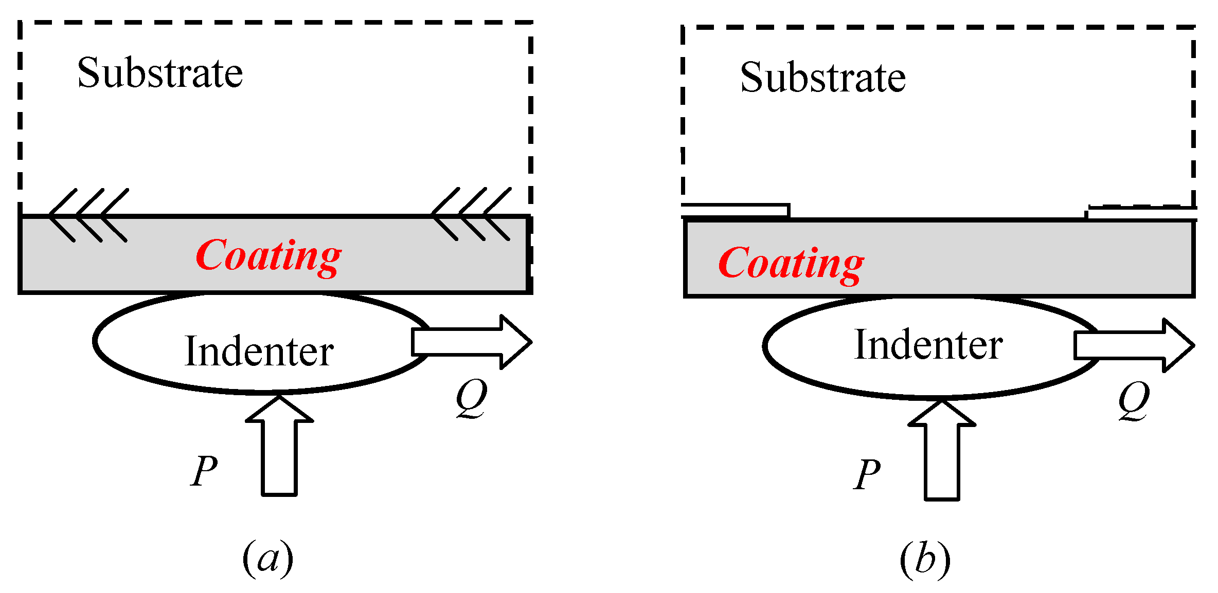
5.2. Multi-Layer Coated Contact

To moderate stress distribution, some elegant multi-layer designs for coating systems were proposed. In the process, stress analysis has been indispensably performed by many researchers. For example, the effect of friction on subsurface stresses was investigated arising from the two-dimensional sliding contact of two multilayered elastic solids [55]. The analysis incorporates bonded and unbonded interface boundary conditions between the coating layers. The plane problem of surface loading of double elastic layers perfectly bonded to an elastic dissimilar half-plane was solved, in which fundamental solutions are obtained for forces acting perpendicular and parallel to the layer surface [56]. The frictionless two-dimensional contact problem was investigated with three-layer coating [57]. Later on, they proposed a semi-analytical model for the two-dimensional contact problem involving a multi-layered elastic solid loaded normally and tangentially by a rigid punch [57,58]. The stress state was modelled in a multi-layer coated system to elaborately design a multilayer coating to increase fretting fatigue life [59]. Recently, adhesive contact between a rigid spherical indenter and an elastic multi-layer coated half-space was investigated [60]. The indented multi-layers were considered as isotropic ones that are perfectly bonded to each other and to an isotropic substrate.
As mentioned before, the formulation methods for multi-layer coated contact just follow the previous ones for the single-layer coating systems. However, the study of multi-layered coated contact problems is a natural requirement for coating design and optimization.

5.3. Functionally Graded Material Coating (FGM)

To approximate the through-thickness variation of Young’s modulus of a piecewise multi-layer coating, functionally graded material coating has been proposed in the literature. This has been a very hot research topic in the last two decades. Roughly speaking, there are three types of functionally graded material coatings adopted during modeling: linear graded layer, exponentially graded layer, and a power-law variation layer.
The contact of a rigid cylinder was first examined on an elastic graded substrate [61]. The normal, sliding and rolling types of contact were addressed. The effect of adhesion in frictionless contact was also examined. The two-dimensional frictionless contact problem was investigated for a coating structure consisting of a surface coating, a functionally graded layer and a substrate under a rigid cylindrical punch [62]. On the other hand, the plane problem of a frictionless receding contact (between an elastic functionally graded layer and a homogeneous half-space) was considered, when the two bodies are pressed together [63]. The effect of the material non-homogeneity parameter and the thickness of the graded layer on the contact pressure and on the length of the receding contact were analyzed. More complicatedly, the frictional receding contact problem for two graded layers pressed by a rigid punch has been considered [64]. In addition, the problem of thermoelastic contact mechanics for the coating/substrate system with functionally graded properties has been investigated [65], in which frictional heat generation inside the contact region due to sliding of the indenter over the half-plane surface is taken into account.
The above three groups are only concerned about the traditional coated contact problems. Recently, some new trend studies in coated contact problems have been explored. For example, dynamic frictional contacts were initially investigated. A general theory was presented for the dynamic frictional contact of elastic coatings pressed against by a rigid punch moving with a constant speed [66]. Also, the dynamic sliding contacts between a functionally graded coating and a rigid moving cylindrical punch have been analyzed [67,68]. It has been found that the dynamic effect may be quite significant. In addition, anisotropic coating effect has also been modeled in contact problem. Sliding contact analysis of a finite thickness orthotropic graded coating was employed [69]. Three-dimensional solutions were obtained for transversely isotropic coated structure under circular flat punch contact, in which the optimal thickness of the coating has been studied [70]. Evidently, these analyses will contribute to the delicate design of the coated structure.
Finally, it should be emphasized again that, most of the classical problems of the contact mechanics field have been attacked with the singular integral equation approach [71]. This approach actually can be traced back to the development of contact mechanics of uncoated systems [72,73]. This approach is more convenient and straightforward than the Finite Element Method when used for simplified contact configurations and linear elastic material response. For material selection and preliminary design this approach may be much more efficient than FEM. However, because FEM is able to effectively deal with the contacts with arbitrary complex geometry and complex material constitutive laws, it is indispensably employed [74,75,76,77,78,79,80,81,82,83].

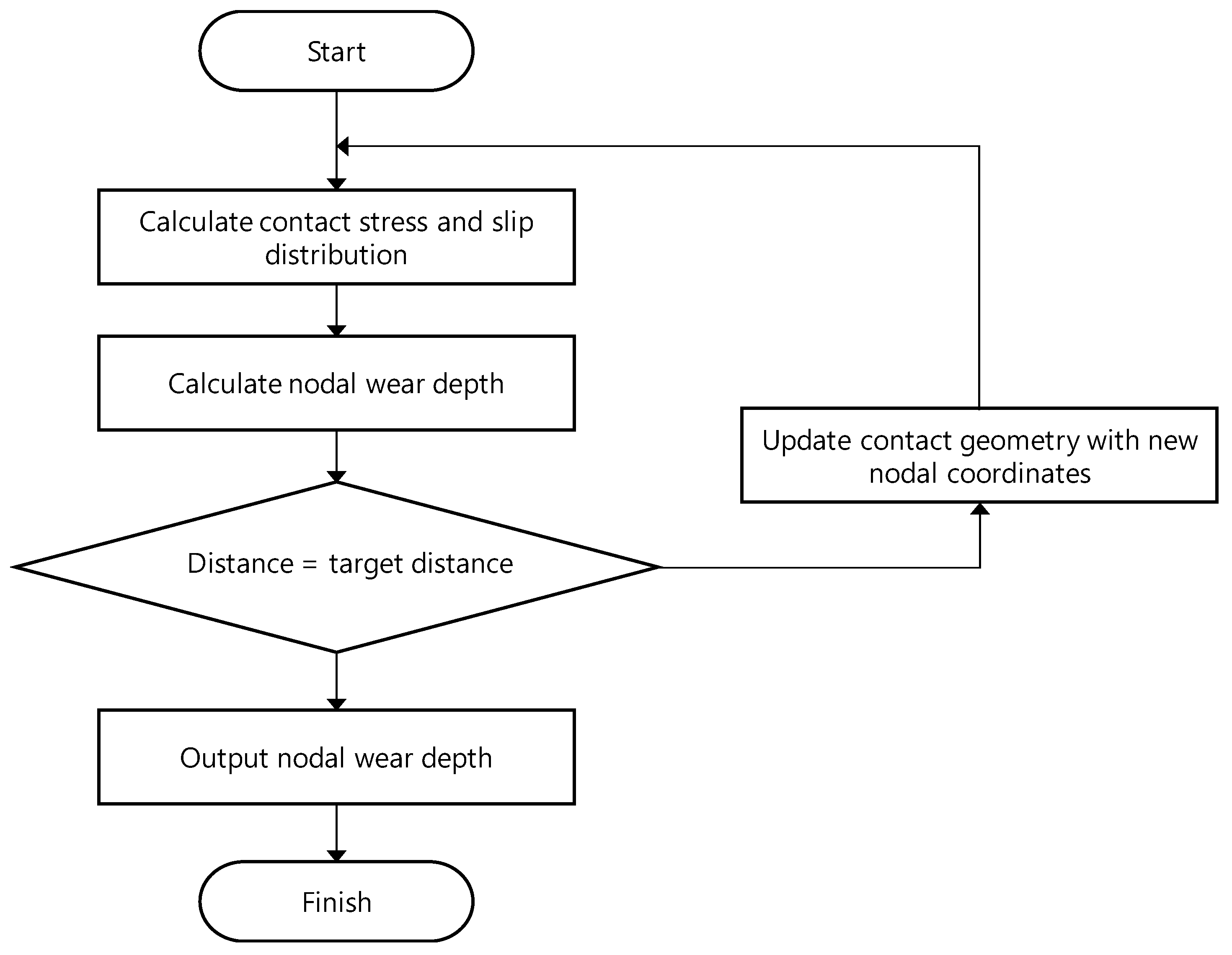
6. Simulation for Fretting

Fretting wear is known as a complex contact phenomenon. A variety of factors, including surface roughness, have an influence on the fretting wear process. Thus, difficulty in simulating fretting wear persists. Some attempts are made to simulate fretting wear and to predict the lifetime of fretting wear. The Archard wear model is modified for introducing a methodology for numerical fretting wear simulation. Equation (4) presents the incremental wear depth based on the local implementation of the Archard wear model [84].
Δ h ( x , t ) = k 1 p ( x , t ) Δ s ( x , t )
where, Δh is the incremental wear depth, k1 is the local Archard coefficient, p is the local contact pressure and Δs is the relative displacement increment.
Figure 12 shows the flow chart for conventional wear simulation using the McColl’s approach [85]. During an interactive process, contact pressure and slip distribution are calculated at a discrete time increment. For the calculation of nodal wear depth, the Archard wear equation is used, shown in Equation (5). Wear volume (V) is determined with the wear coefficient, sliding distance, and normal force.
V = k·P·s
where, k is the wear coefficeint determined experimentally, s and P denote the sliding distance and normal force, respectively.
Contact geometry is updated until the distance meets a target value. Finally, the nodal wear depth is determined and worn geometry is presented at the end of the cycle. This wear simulation could be used for the fretting wear of a coated system.
Other fretting wear models were proposed on the basis of friction dissipated energy, boundary element formulation, and so on. For a fretting model, Archard’s wear law was modified, based on the friction dissipated energy [86,87]. A wear coefficient in the wear law was determined with the accumulation of dissipated energy. An energy wear model considering the interfacial shear work was developed [86].
V = α   E d
where, V is the fretting wear volume, and α denotes the energy wear coefficient. Ed is dissipated energy. The dissipated energy is calculated in each fretting loop and accumulated until the final cycle. Note that the dissipated energy is equal to the area within a fretting loop.
A boundary element method formation was proposed for 3D fretting problem [88]. The loss of material was modeled using the Holm–Archard linear wear law. The change in the geometry due to the wear process was taken into account via the gap variable. A finite element model was developed for simulating fretting wear and the evolution of a wear profile with respect to fretting cycle [85]. The model using experimental data determined worn surface profiles according to number of fretting cycles. The validation of the model was employed with fretting wear testing results. During a fretting cycle, a wear debris is entrapped within the contact zone. The model considering the effect of debris was developed [89]. The debris accumulated on the fretting interface was considered as a layer structure and described by an elastic-plastic material model. A semi-analytical model was simulated for fretting wear with entrapped debris [90]. In the model, it was assumed that debris was attached to one of the contact surfaces during a fretting cycle. The proposed model captured the wear depth and scar width. A fretting wear model incorporating the evolution of the debris layer was proposed to predict the wear profile under various fretting conditions [91]. For describing the evolution of the debris layer, the dynamic volume fraction of ejected particles was considered, related to the accumulation of trapped debris volume. A finite element model was developed for simulating a fretting wear profile [92]. The model considered the presence of a third body layer evolving over fretting time. A finite element based methodology was proposed for predicting the influence of fretting wear on crack under fretting fatigue condition [93]. A wear model was combined with multiaxial predictions of crack nucleation and of linear elastic fracture mechanics. Various contact models for rough surface were proposed [94,95,96,97,98]: basic elastic and plastic contact models were introduced, respectively [94,95]. An elastic-plastic asperity model was proposed for analyzing rough surface [96,97]. This model considered volume conservation of plastically deformed asperities, implemented into a finite element framework. An elastic-plastic asperity contact model was proposed for a rough surface with a soft thin metallic coating [98].
In order to achieve rapid simulation, the incremental wear model using the Reye–Archard–Khrushchov wear criterion was proposed [99]. The distributions of contact pressure and relative displacements were calculated using the method of dimensionality reduction. In the models described above, the coefficient of friction was assumed to be constant during a fretting cycle. Some studies considered the varied friction in a fretting wear model [99,100]. A torsional fretting wear model based on varied friction was proposed [100]. In the model, a variable friction coefficient governed by the local contact history was introduced. The evolution of the friction coefficient was applied to calculate wear volume in a gross slip regime [101]. It was identified that a finite element model using varied friction coefficient provided a similar result with experimental results. A dry fretting wear model using a stress-based damage mechanics equation was proposed for similar materials in Hertizan contact [102]. In the model, fatigue crack initiation and propagation in a material microstructure and grain removal were considered. The simulation result offered two distinct regions, wear initiation and wear propagation.
In order to simulate fretting problems, it is necessary to understand friction. For understanding the physical origin of friction, for recent decades, there have been atomic force microscopy (AFM)-based friction experiments, which consider the friction between AFM tip and surface [103,104]. This AFM-based friction experiment has led researchers to gain a fundamental insight into how the frictional properties can be determined based on a simple frictional situation, that is, a single contact between AFM tip and surface was formed and then was ruptured followed by re-formation of such a contact. The friction force measured in AFM experiments is found to be dependent on the velocity of AFM tip as well as temperature [103,104]. This relationship between friction force and tip velocity (and also temperature) was theoretically described by the Prandtl–Tomlinson model, which assumes that a particle modeling an AFM tip is moving in a one-dimensional, periodic energy landscape that dictates the interaction between AFM tip and surface [105,106,107,108]. In addition to AFM experiment with a theoretical model such as the Prandtl–Tomlinson model, atomistic simulations such as molecular dynamics (MD) simulations have allowed for unveiling the physical origin of frictional properties. Here, the principle of MD simulation is to numerically solve Newton’s equation of motion for all atoms of a material system under mechanical process [109,110,111]. In recent decades, MD simulations have played an unprecedented role in gaining insight into nanoscale phenomena including, but not limited to, protein dynamics [109,110,111], nanomaterial behaviors [112,113], and (nanoscale) frictions [114]. In particular, MD simulations have successfully validated the Prandtl–Tomlinson model by simulating the friction of Pt tip sliding on a gold atomic surface [104]. Moreover, the MD simulation has enabled insight into the underlying mechanisms of the unique frictional behavior of two-dimensional material such as graphene (e.g., strengthening of static friction for a few initial atomic periods before reaching a constant value) [115]. The MD simulation result showed that the unique frictional behavior of graphene is attributed to the time-evolution dynamics (i.e., configurational relaxation) of out-of-plane floppiness for few-layer two-dimensional material (e.g., graphene monolayer).

7. Future Challenges

In the aerospace industry, composite is known as a promising material. Fan blades in some aero-engines are made of a metal matrix composite. Due to the change of the underlying material, new coatings need to be selected to resist fretting wear damage. Thus, composite-based materials are being tested to identify the suitability of a component subjected to fretting. In nuclear industry, a fretting-resistant coating is being developed to increase the anti-fretting lifetime of a fuel rod. In addition, contact geometry between a spring and a dimple needs to be determined to minimize contact stress. For an automotive component, a coating maintaining low deposition cost is needed. In the biomedical industry, biocompatible coating material continues to be developed. Thus, application to hip implants will be conducted as well as a fretting wear test.
In order to investigate the fretting problems in coated contacts, the first step is to find contact traction and stress state in the coated systems. It is also the main topic of contact mechanics. Great efforts have been paid, however, to the best of the authors’ knowledge, there are two challenging aspects still need to be paid close attentions: (1) the anisotropic mechanical properties of coating materials. As we know, the coatings are manufactured by employing special production techniques such as thermal spraying and electron beam physical vapor deposition. Coatings deposited by thermal spray methods are known to possess a lamellar structure parallel to the interface, while electron beam physical vapor deposition technique leads to a columnar structure perpendicular to the interface. How to evaluate such orthotropic structures’ influence on stress distribution in whole coated contact systems needs to be explored [69]; (2) at a micro-scale, contacted surfaces actually are very rough, the micro-asperities distributed along the contact surfaces will significantly influence the traction distribution [43], and more importantly, they will inevitably lead to fretting fatigue and wear with tangential load. Micro-contact analysis needs to be thoroughly performed.
Despite the ability of MD simulations to depict the physical origin of nanoscale friction such as AFM tip-surface friction [104,114], they are still limited for studying the generic friction problems. As the time-scale accessible with MD simulation is currently at most less than milli-second (typically, at most 10 to 100 micro-seconds) [116], MD simulation may not be able to depict the nanoscale friction behavior at the very low sliding speed, at which smooth sliding might occur. In other words, MD simulation may be appropriate for studying the stick-slip friction behavior, while it may be still inappropriate for understanding the smooth sliding friction behavior. In addition, although it may be of interest to study the transition between stick-slip friction and smooth sliding friction, MD simulation is still restricted in studying such a transition. Moreover, MD simulation may be computationally prohibited for understanding the frictional ageing observed by the AFM experiment (that is, single-asperity slide-hold-slide friction experiment under humidity). The computational limitation of MD simulation for studying such a frictional ageing is due to the fact that a large number of water molecules (or liquid molecules) surrounding the tip and surface atoms significantly increases the computational cost of simulation. In addition, for a realistic frictional behavior at macroscopic scale, there are a lot of contacts (rather than a single contact between tip and surface) during the friction between two material systems. To the best of our knowledge, the multiple contacts between two material systems (with their length scale of >100 nm) have not been modeled and simulated based on MD due to its limited accessible length scale of at most 100 nm and time-scale of at most 10–100 microseconds. These limited spatial and temporal scales of MD indicate that MD simulation is still computationally challenging for studying the generic friction problems such as transition between smooth sliding friction and stick-slip friction, frictional ageing, friction with multiple contacts, and so forth, albeit the MD simulation is able to reveal the fundamental, underlying mechanisms of some frictional properties and behaviors such as stick-slip friction (with a single contact between tip and surface). In spite of the pitfalls of MD simulations for studying the generic friction problems, we anticipate that as the computational power has been enormously increased for a recent decade (i.e., from ~1 peta-flops in year 2008 to >100 peta-flops), within next <10 years, MD simulation will gain computational ability to simulate more realistic friction problems (as mentioned earlier, such as transition from stick-slip friction to smooth sliding friction, frictional ageing, friction with multiple contacts, and so on).

8. Concluding Remarks

Fretting wear is observed in various industries. But, at most contact surfaces found in the industries, the primary practical solution to resist fretting wear damage is the deposition of a low friction coating on contact surfaces. Anti-fretting coatings selected in industries are various according to contact force and displacement magnitudes. In an aerospace blade-disc interface, high contact pressure is found compared to those found in nuclear, biomedical and automotive components. A thermally sprayed double layer coating containing Cu, Ni, In with MoS2 is selected at the contact surface between a blade root and a disc. In nuclear components, fretting wear occurs in wet conditions. Fuel rod vibration arisen from flowing water leads to high frequency. A thermal sprayed coating is deposited at the surface of a fuel rod to resist fretting wear. In a biomedical component, biocompatibility is of importance, thus hydroxyapatite coatings are being used. In automotive connectors, electroplated brass with nickel, tin or gold is selected to resist fretting wear damage.
In order to evaluate fretting damage during a test, the kinetic friction coefficient is mainly used for aerospace and nuclear components. A fretting loop consisting of a tangential force and a relative displacement is used to identify a slip regime. But, for biomedical components, open circuit potential (OCP) is monitored along with the friction coefficient to identify the contact damage. For automotive components, an electric contact resistance is selected to identify the critical contact damage state.
For the purpose of understanding fretting damage of a coating, contact mechanics of a coated system were reviewed. In this paper, a coated contact problem was classified into a single layer, multi-layer, and functionally graded material layer. Contact stress distributions were identified in the coating layer and the substrate. During the design of a coating, contact problems classified into three cases will be useful.
A variety of fretting wear models were reviewed based on friction dissipated energy and boundary element formulation. Such models were implemented into finite element framework. The models were verified with fretting wear result. However, actual use of the models was limited due to complex fretting wear phenomenon. Thus, in this paper, nano-scale modelling using molecular dynamics (MD) was reviewed to simulate the origin of friction and fretting. It is anticipated that as the computational power has been enormously increased in the last decade, MD simulation will gain computational ability to simulate fretting problems.
In this review paper, it was identified that fretting wear damage is observed in aerospace, biomedical, automotive and nuclear industries. In other industries, there also exist some components subjected to fretting wear. Possible solutions to resist fretting wear found in the above-mentioned components might be sought in this review paper.

Author Contributions

Conceptualization, L.M., J.G., K.E., T.-S.J. and K.K.; Writing—Original Draft Preparation, L.M., J.G., K.E., and K.K.; Writing—Review and Editing, L.M., J.G., K.E., T.-S.J. and K.K.

Funding

This work has supported by the National Research Foundation of Korea (NRF) grant funded by the Korea government (MSIT) (No. 2019R1A2C1007515).

Conflicts of Interest

The authors declare no conflict of interest.

Appendix A

A Mechano-chemical coatings and direct comparison on anti-fretting lifetime under conditions similar to those found in the interface between a blade root and a disc.
NumberCoatingAnti-Fretting Lifetime Ratio 1
1CuNiIn+MoS21.00
2Mo+S1.05
3SiC-Mo-MoS21.21
4SiC-Mo-MoS21.21
1 Note that anti-fretting lifetime ratio was defined as the ratio of the lifetime of a coating to that of CuNiIn+MoS2 coating.

References

  1. Hills, D.A.; Nowell, D. Mechanics of Fretting Fatigue, 1st ed.; Springer: Berlin/Heidelberg, Germany, 1994. [Google Scholar]
  2. Vingsbo, O.; Soderberg, S. On Fretting Maps. Wear 1988, 126, 131–147. [Google Scholar] [CrossRef]
  3. Kim, K. An Investigation of Fretting Wear and Fretting Fatigue of Coated Systems. Ph.D. Thesis, University of Oxford, Oxford, UK, 2005. [Google Scholar]
  4. Fouvry, S.; Kapsa, P.; Vincent, L. An elastic–plastic shakedown analysis of fretting wear. Wear 2001, 247, 41–54. [Google Scholar] [CrossRef]
  5. Zhou, Z.R.; Nakazawa, K.; Zhu, M.H.; Maruyama, N.; Kapsa, P.; Vincent, L. Progress in fretting maps. Tribol. Inl. 2006, 39, 1068–1073. [Google Scholar] [CrossRef]
  6. Geringer, J.; Macdonald, D. Friction/fretting-corrosion mechanisms: Current trends and outlooks for implants. Mater. Lett. 2014, 134, 152–157. [Google Scholar] [CrossRef]
  7. Wu, Y.P.; Li, Z.Y.; Zhu, S.F.; Lü, L.; Cai, Z.B. Effect of frequency on fretting wear behavior of Ti/TiN multilayer film on depleted uranium. PLoS ONE 2017, 12, 0175084. [Google Scholar] [CrossRef] [PubMed]
  8. Kubiak, K.; Mathia, T.; Fouvry, S.; Kubiak, K. Interface roughness effect on friction map under fretting contact conditions. Tribol. Int. 2010, 43, 1500–1507. [Google Scholar] [CrossRef] [Green Version]
  9. Korsunsky, A.M.; Torosyan, A.R.; Kim, K. Development and characterization of low friction coatings for protection against fretting wear in aerospace components. Thin Solid Film. 2008, 516, 5690–5699. [Google Scholar] [CrossRef]
  10. Kim, K.; Geringer, J.; Pellier, J.; Macdonald, D.D. Fretting corrosion damage of total hip prosthesis: Friction coefficient and damage rate constant approach. Tribol. Int. 2013, 60, 10–18. [Google Scholar] [CrossRef]
  11. Kim, K. Fretting studies on electroplated brass contacts. Int. J. Mech. Sci. 2018, 140, 306–312. [Google Scholar] [CrossRef]
  12. Kim, H.K.; Lee, Y.H.; Heo, S.P. Mechanical and experimental investigation on nuclear fuel fretting. Tribol. Int. 2016, 39, 1305–1319. [Google Scholar] [CrossRef]
  13. Beale, S. Precision engineering for future propulsion and power systems: A perspective from Rolls-Royce. Philos. Trans. R. Soc. A Math. Phys. Eng. Sci. 2012, 370, 4130–4153. [Google Scholar] [CrossRef] [PubMed]
  14. Geringer, J.; Forest, B.; Combrade, P. Fretting-corrosion of materials used as orthopaedic implants. Wear 2005, 259, 943–951. [Google Scholar] [CrossRef] [Green Version]
  15. Antler, M. Survey of contact fretting in electrical connectors. IEEE Trans. Compon. Hybrids Manuf. Technol. 1985, 8, 87–104. [Google Scholar] [CrossRef]
  16. van Dijk, P.; Rudolphi, A.K.; Klaffke, D. Investigations on Electrical Contacts Subjected to Fretting Motion. In Proceedings of the 21st International Conference on Electrical Contacts (ICEC), Zurich, Switzerland, 9–12 September 2002. [Google Scholar]
  17. Sung, I.; Kim, J.; Noh, H.; Jang, H. Effect of displacement and humidity on contact resistance of copper electrical contacts. Tribol. Int. 2016, 95, 256–261. [Google Scholar] [CrossRef]
  18. Kim, H.K.; Lee, Y.H.; Lee, K.H. On the geometry of the fuel rod supports concerning a fretting wear failure. Nucl. Eng. Des. 2008, 238, 3321–3330. [Google Scholar] [CrossRef]
  19. Bhushan, B. Introduction to Tribology, 1st ed.; John Wiley & Sons: New York, NY, USA, 2002; p. 180. [Google Scholar]
  20. Geringer, J.; Pellier, J.; Taylor, M.L.; Macdonald, D.D. Fretting corrosion with proteins: The role of organic coating on the synergistic mechanisms. Thin Solid Films 2013, 528, 123–129. [Google Scholar] [CrossRef]
  21. Fouvry, S.; Kapsa, P.; Vincent, L. Analysis of sliding behaviour for fretting loadings: Determination of transition criteria. Wear 1995, 185, 35–46. [Google Scholar] [CrossRef]
  22. Varenberg, M.; Etsion, I.; Halperin, G. Slip Index: A new unified approach to fretting. Tribol. Lett. 2004, 17, 569–573. [Google Scholar] [CrossRef]
  23. Kim, K. Statistical determination of a fretting-induced failure of an electro-deposited coating. Coatings 2017, 7, 48. [Google Scholar] [CrossRef]
  24. Kim, K.; Korsunsky, A.M. Effects of imposed displacement and initial coating thickness on fretting behaviour of a thermally sprayed coating. Wear 2011, 271, 1080–1085. [Google Scholar] [CrossRef]
  25. Korsunsky, A.M.; Kim, K. Dissipated energy and friction coefficient evolution during fretting wear of solid lubricant coatings. Tribol. Int. 2010, 43, 861–867. [Google Scholar] [CrossRef]
  26. Noel, S.; Correia, S.; Alamarguy, D.; Gendre, P. Fretting behavior of various intermetallic compound influence on reliability. Wear 2011, 271, 1515–1523. [Google Scholar] [CrossRef]
  27. Kim, K.; Korsunsky, A.M. Dissipated energy and fretting damage in CoCrAlY-MoS2 coatings. Tribol. Int. 2010, 43, 676–684. [Google Scholar] [CrossRef]
  28. Kim, K.; Korsunsky, A.M.; Korsunsky, A. Fretting damage of Ni—MoS2 Coatings: Friction coefficient and accumulated dissipated energy evolutions. Proc. Inst. Mech. Eng. Part J. J. Eng. Tribol. 2010, 224, 1173–1180. [Google Scholar] [CrossRef]
  29. Fridrici, V.; Fouvry, S.; Kapsa, P. Effect of shot peening on the fretting wear of Ti–6Al–4V. Wear 2001, 250, 642–649. [Google Scholar] [CrossRef]
  30. De Aza, A.H.; Chevalier, J.; Fantozzi, G.; Schehl, M.; Torrecillas, R. Crack growth resistance of alumina, zirconia and zirconia toughened alumina ceramics for joint prostheses. Biomaterials 2002, 23, 937–945. [Google Scholar] [CrossRef]
  31. Kim, K.; Geringer, J.; Macdonald, D.D. Crack simulation of nano-bioceramic composite microstructures with cohesive failure law: Effects of sintering, loads and time. J. Mech. Behav. Biomed. Mater. 2012, 15, 1–12. [Google Scholar] [CrossRef] [PubMed]
  32. England, A.H.; Green, A.E. A punch problem for a transversely isotropic layer. Math. Proc. Camb. Philos. Soc. 1962, 58, 539. [Google Scholar] [CrossRef]
  33. Wu, T.S.; Chiu, Y.P. On the contact problem of layered elastic bodies. Q. Appl. Math. 1967, 25, 233–242. [Google Scholar] [CrossRef] [Green Version]
  34. Ma, L.; Korsunsky, A.; Korsunsky, A. Fundamental formulation for frictional contact problems of coated systems. Int. J. Solids Struct. 2004, 41, 2837–2854. [Google Scholar] [CrossRef]
  35. Bentall, R.H.; Johnson, K.L. An elastic strip in plan rolling contact. Int. J. Mech. Sci. 1968, 10, 637–663. [Google Scholar] [CrossRef]
  36. Walowit, J.A.; Gupta, P.K. Contact stresses between an elastic cylinder and a layered elastic solid. J. Lubr. Technol. 1974, 96, 250–257. [Google Scholar]
  37. King, R.; O’Sullivan, T. Sliding contact stresses in a two-dimensional layered elastic half-space. Int. J. Solids Struct. 1987, 23, 581–597. [Google Scholar] [CrossRef]
  38. Jaffar, M.J.; Savage, M.D. On the numerical solution of line contact problems involving bonded and unbonded strips. J. Strain Anal. Eng. Des. 1988, 23, 67–77. [Google Scholar] [CrossRef]
  39. Porter, M.; Hills, D. Note on the complete contact between a flat rigid punch and an elastic layer attached to a dissimilar substrate. Int. J. Mech. Sci. 2002, 44, 509–520. [Google Scholar] [CrossRef]
  40. Ma, L.F.; Korsunsky, A.M. Solution of sliding contact problems using Gauss-Jacobi quadrature formulae. Int. J. Numer. Methods Eng. 2005, 64, 1236–1255. [Google Scholar] [CrossRef]
  41. Ma, L.F.; Korsunsky, A.M.; Sun, K. The contact of coated systems under sliding conditions. J. Tribol. Trans. ASME 2006, 128, 886–890. [Google Scholar] [CrossRef]
  42. Comez, I.; Erdol, R. Frictional contact problem of a rigid stamp and an elastic layer bonded to a homogeneous substrate. Arch. Appl. Mech. 2013, 83, 15–24. [Google Scholar] [CrossRef]
  43. Nowell, D.; Hills, D. Contact problems incorporating elastic layers. Int. J. Solids Struct. 1988, 24, 105–115. [Google Scholar] [CrossRef]
  44. Sackfield, A.; Hills, D.A.; Nowell, D. Mechanics of Elastic Contacts, 1st ed.; Butterworth-Heinemann: Oxford, UK, 1993. [Google Scholar]
  45. Krenk, S. On quadrature formulas for singular integral equations of the first and the second kind. Q. Appl. Math. 1975, 33, 225–232. [Google Scholar] [CrossRef] [Green Version]
  46. Erdogan, F.; Gupta, G.D.; Cook, T.S. Numerical solution of singular integral equations. In Methods of Analysis and Solutions of Crack Problems; Springer Science and Business Media LLC: Berlin, Germany, 1973; pp. 368–425. [Google Scholar]
  47. Korsunsky, A.M. On the use of interpolative quadratures for hypersingular integrals in fracture mechanics. Proc. R. Soc. A Math. Phys. Eng. Sci. 2002, 458, 2721–2733. [Google Scholar] [CrossRef]
  48. Keer, L.M.; Dundurs, J.; Tsai, K.C. Problems involving a receding contact between a layer and a half space. J. Appl. Mech. 1972, 39, 1115–1120. [Google Scholar] [CrossRef]
  49. Ratwani, M.; Erdogan, F. On the plane contact problem for a frictionless elastic layer. Int. J. Solids Struct. 1973, 9, 921–936. [Google Scholar] [CrossRef]
  50. Reina, S.; Hills, D.; Dini, D. Contact of a rigid cylinder indenting an elastic layer sliding over a rigid substrate. Eur. J. Mech. A Solids 2010, 29, 772–783. [Google Scholar] [CrossRef]
  51. Comez, I. Frictional contact problem for a rigid cylindrical stamp and an elastic layer resting on a half plane. Int. J. Solids Struct. 2010, 47, 1090–1097. [Google Scholar] [CrossRef] [Green Version]
  52. Chaise, T.; Paynter, R.; Hills, D. Contact analysis of a semi-infinite strip pressed onto a half plane by a line force. Int. J. Mech. Sci. 2014, 81, 60–64. [Google Scholar] [CrossRef]
  53. Parel, K.; Hills, D. Frictional receding contact analysis of a layer on a half-plane subjected to semi-infinite surface pressure. Int. J. Mech. Sci. 2016, 108, 137–143. [Google Scholar] [CrossRef]
  54. Sergici, A.O.; Adams, G.G.; Müftü, S. Adhesion in the contact of a spherical indenter with a layered elastic half-space. J. Mech. Phys. Solids 2006, 54, 1843–1861. [Google Scholar] [CrossRef]
  55. Elsharkawy, A.A. Effect of friction on subsurface stresses in sliding line contact of multilayered elastic solids. Int. J. Solids Struct. 1999, 36, 3903–3915. [Google Scholar] [CrossRef]
  56. Shakeri, M.; Sadough, A.; Ahmadi, S.R. Elastic stress analysis of bi-layered isotropic coatings and substrate subjected to line scratch indentation. J. Mater. Process. Technol. 2008, 196, 213–221. [Google Scholar] [CrossRef]
  57. Chidlow, S.; Teodorescu, M. Two-dimensional contact mechanics problems involving inhomogeneously elastic solids split into three distinct layers. Int. J. Eng. Sci. 2013, 70, 102–123. [Google Scholar] [CrossRef] [Green Version]
  58. Chidlow, S.; Teodorescu, M. Sliding contact problems involving inhomogeneous materials comprising a coating-transition layer-substrate and a rigid punch. Int. J. Solids Struct. 2014, 51, 1931–1945. [Google Scholar] [CrossRef] [Green Version]
  59. Ibrahim, R.; Rahmat, M.; Oskouei, R.; Raman, R.S. Monolayer TiAlN and multilayer TiAlN/CrN PVD coatings as surface modifiers to mitigate fretting fatigue of AISI P20 steel. Eng. Fract. Mech. 2015, 137, 64–78. [Google Scholar] [CrossRef]
  60. Stan, G.; Adams, G.G. Adhesive contact between a rigid spherical indenter and an elastic multi-layer coated substrate. Int. J. Solids Struct. 2016, 87, 1–10. [Google Scholar] [CrossRef] [PubMed]
  61. Giannakopoulosa, A.E.; Pallot, P. Two-dimensional contact analysis of elastic graded materials. J. Mech. Phys. Solids 2000, 48, 1597–1631. [Google Scholar] [CrossRef]
  62. Yang, J.; Ke, L.L. Two-dimensional contact problem for a coating–graded layer–substrate structure under a rigid cylindrical punch. Int. J. Mech. Sci. 2008, 50, 985–994. [Google Scholar] [CrossRef]
  63. El-Borgi, S.; Abdelmoula, R.; Keer, L. A receding contact plane problem between a functionally graded layer and a homogeneous substrate. Int. J. Solids Struct. 2006, 43, 658–674. [Google Scholar] [CrossRef] [Green Version]
  64. Yilmaz, K.; Comez, I.; Yildirim, B.; Güler, M.; El-Borgi, S. Frictional receding contact problem for a graded bilayer system indented by a rigid punch. Int. J. Mech. Sci. 2018, 141, 127–142. [Google Scholar] [CrossRef]
  65. Choi, H.J.; Paulino, G.H. Thermoelastic contact mechanics for a flat punch sliding over a graded coating/substrate system with frictional heat generation. J. Mech. Phys. Solids 2008, 56, 1673–1692. [Google Scholar] [CrossRef]
  66. Balci, M.N.; Dag, S. Dynamic frictional contact problems involving elastic coatings. Tribol. Int. 2018, 124, 70–92. [Google Scholar] [CrossRef]
  67. Alinia, Y.; Beheshti, A.; Guler, M.A.; El-Borgi, S.; Polycarpou, A.A. Sliding contact analysis of functionally graded coating/substrate system. Mech. Mater. 2016, 94, 142–155. [Google Scholar] [CrossRef]
  68. Balci, M.N.; Dag, S. Solution of the dynamic frictional contact problem between a functionally graded coating and a moving cylindrical punch. Int. J. Solids Struct. 2019, 161, 267–281. [Google Scholar] [CrossRef]
  69. Arslan, O.; Dag, S. Contact mechanics problem between an orthotropic graded coating and a rigid punch of an arbitrary profile. Int. J. Mech. Sci. 2018, 135, 541–554. [Google Scholar] [CrossRef]
  70. Hou, P.F.; Zhang, W.H.; Chen, J.Y. Three-dimensional exact solutions of transversely isotropic coated structures under tilted circular flat punch contact. Int. J. Mech. Sci. 2019, 151, 471–497. [Google Scholar] [CrossRef]
  71. Tichy, A.J.; Meyer, D.M. Review of solid mechanics in tribology. Int. J. Solids Struct. 2000, 37, 391–400. [Google Scholar] [CrossRef]
  72. Gladwell, G.M.L. Contact Problems in the Classical Theory of Elasticity; Springer Science and Business Media LLC: Berlin, Germany, 1980. [Google Scholar]
  73. Johnson, K.L. Contact Mechanics; Cambridge University Press: Cambridge, UK, 1985. [Google Scholar]
  74. Ihara, T.; Shaw, M.C.; Bhushan, B. A finite element analysis of contact stress and strain in an elastic film on a rigid substrate—Part I: Zero friction. J. Tribol. Trans. ASME 1986, 108, 527–533. [Google Scholar] [CrossRef]
  75. Ihara, T.; Shaw, M.C.; Bhushan, B. A finite element analysis of contact stress and strain in an elastic film on a rigid substrate—Part II: With friction. J. Tribol. 1986, 108, 534–539. [Google Scholar] [CrossRef]
  76. Komovopoulus, K. Finite element analysis of a layered elastic solid in normal contact with a rigid substrate. J. Tribol. Trans. ASME 1988, 110, 477–485. [Google Scholar] [CrossRef]
  77. Tian, H.; Saka, N. Finite element analysis of an elastic-plastic two-layer half-space: Sliding contact. Wear 1991, 148, 261–285. [Google Scholar] [CrossRef]
  78. Anderson, I.; Collins, I. Plane strain stress distributions in discrete and blended coated solids under normal and sliding contact. Wear 1995, 185, 23–33. [Google Scholar] [CrossRef]
  79. Oliveira, S.A.; Bower, A.F. An analysis of fracture and delamination in thin coatings subjected to contact loading. Wear 1996, 198, 15–32. [Google Scholar] [CrossRef]
  80. Lovell, M. Analysis of contact between transversely isotropic coated surfaces: Development of stress and displacement relationships using FEM. Wear 1998, 214, 165–174. [Google Scholar] [CrossRef]
  81. Aslantas, K.; Tasgetiren, S. Debonding between coating and substrate due to rolling–sliding contact. Mater. Des. 2002, 23, 571–576. [Google Scholar] [CrossRef]
  82. Abdul-Baqi, A.; Van Der Giessen, E. Numerical analysis of indentation-induced cracking of brittle coatings on ductile substrates. Int. J. Solids Struct. 2002, 39, 1427–1442. [Google Scholar] [CrossRef] [Green Version]
  83. Chai, H. Fracture mechanics analysis of thin coatings under plane-strain indentation. Int. J. Solids Struct. 2003, 40, 591–610. [Google Scholar] [CrossRef]
  84. Archard, J.F.; Hirst, W. The wear of metals under unlubricated conditions. Proc. R. Soc. Ser. A Math. Phys. Sci. 1956, 236, 397–410. [Google Scholar]
  85. McColl, I.; Ding, J.; Leen, S.; Leen, S. Finite element simulation and experimental validation of fretting wear. Wear 2004, 256, 1114–1127. [Google Scholar] [CrossRef]
  86. Fouvry, S.; Kapsa, P.; Vincent, L. Quantification of fretting damage. Wear 1996, 200, 186–205. [Google Scholar] [CrossRef]
  87. Shen, F.; Hu, W.; Meng, Q. A damage mechanics approach to fretting fatigue life prediction with consideration of elastic–plastic damage model and wear. Tribol. Int. 2015, 82, 176–190. [Google Scholar] [CrossRef]
  88. Rodríguez-Tembleque, L.; Abascal, R.; Aliabadi, M. A boundary elements formulation for 3D fretting-wear problems. Eng. Anal. Bound. Elements 2011, 35, 935–943. [Google Scholar] [CrossRef]
  89. Ding, J.; McColl, I.; Leen, S.; Shipway, P.; Shipway, P. A finite element based approach to simulating the effects of debris on fretting wear. Wear 2007, 263, 481–491. [Google Scholar] [CrossRef]
  90. Done, V.; Kesavan, D.; Krishna R, M.; Chaise, T.; Nelias, D. Semi analytical fretting wear simulation including wear debris. Tribol. Int. 2017, 109, 1–9. [Google Scholar] [CrossRef]
  91. Zhang, L.; Ma, S.; Liu, D.; Zhou, B.; Markert, B. Fretting wear modelling incorporating cyclic ratcheting deformations and the debris evolution for Ti-6Al-4V. Tribol. Int. 2019, 136, 317–331. [Google Scholar] [CrossRef]
  92. Arnaud, P.; Fouvry, S.; Garcin, S. A numerical simulation of fretting wear profile taking account of the evolution of third body layer. Wear 2017, 376, 1475–1488. [Google Scholar] [CrossRef]
  93. Madge, J.; Leen, S.; Shipway, P. A combined wear and crack nucleation–propagation methodology for fretting fatigue prediction. Int. J. Fatigue 2008, 30, 1509–1528. [Google Scholar] [CrossRef]
  94. Greenwood, J.A.; Williamson, J.B.P. Contact of nominally flat surfaces. Proc. R. Soc. 1966, 295, 300–319. [Google Scholar]
  95. Abbott, E.J.; Firestone, F.A. Specifying Surface Quantity—A method based on accurate measurement and comparison. Mech. Eng. 1933, 55, 569. [Google Scholar]
  96. Chang, W.R.; Etsion, I.; Bogy, D.B. An Elastic-Plastic Model for the Contact of Rough Surfaces. J. Tribol. 1987, 109, 257–263. [Google Scholar] [CrossRef]
  97. Kogut, L.; Etsion, I. A finite element based elastic-plastic model for the contact of rough surfaces. Tribol. Trans. 2003, 46, 383–390. [Google Scholar] [CrossRef]
  98. Chang, W.R. An elastic-plastic contact model for a rough surface with an ion-plated soft metallic coating. Wear 1997, 212, 229–237. [Google Scholar] [CrossRef]
  99. Dimaki, A.V.; Dmitriev, A.I.; Chai, Y.S.; Popov, V.L. Rapid simulation procedure for fretting wear on the brass of the method of dimensionality reduction. Int. J. Solids Struct. 2014, 51, 4215–4220. [Google Scholar] [CrossRef]
  100. Liu, J.; Shen, H.; Yang, Y. Finite element implementation of a varied friction model applied to torsional fretting wear. Wear 2014, 314, 220–227. [Google Scholar] [CrossRef]
  101. Yue, T.; Wahab, M.A. Finite element analysis of fretting wear under variable coefficient of friction and different contact regimes. Tribol. Int. 2017, 107, 274–282. [Google Scholar] [CrossRef]
  102. Ghosh, A.; Leonard, B.; Sadeghi, F. A stress based damage mechanics model to simulate fretting wear of Hertzian line contact in partial slip. Wear 2013, 307, 87–99. [Google Scholar] [CrossRef]
  103. Jansen, L.; Hölscher, H.; Fuchs, H.; Schirmeisen, A. Temperature dependence of atomic-scale stick-slip friction. Phys. Rev. Lett. 2010, 104, 256101. [Google Scholar] [CrossRef]
  104. Li, Q.; Dong, Y.; Pérez, D.; Martini, A.; Carpick, R.W. Speed dependence of atomic stick-slip friction in optimally matched experiments and molecular dynamics simulations. Phys. Rev. Lett. 2011, 106, 126101. [Google Scholar] [CrossRef] [PubMed]
  105. Riedo, E.; Gnecco, E.; Bennewitz, R.; Meyer, E.; Brune, H. Interaction potential and hopping dynamics governing sliding friction. Phys. Rev. Lett. 2003, 91, 084502. [Google Scholar] [CrossRef]
  106. Reimann, P.; Evstigneev, M. Nonmonotonic velocity dependence of atomic friction. Phys. Rev. Lett. 2004, 93, 230802. [Google Scholar] [CrossRef]
  107. Evstigneev, M.; Reimann, P. Refined force-velocity relation in atomic friction experiments. Phys. Rev. B 2006, 73, 113401. [Google Scholar] [CrossRef]
  108. Vanossi, A.; Manini, N.; Urbakh, M.; Zapperi, S.; Tosatti, E. Modeling friction: From nanoscale to mesoscale. Rev. Mod. Phys. 2013, 85, 529–552. [Google Scholar] [CrossRef]
  109. Eom, K. Computer simulation of protein materials at multiple length scales: From single proteins to protein assemblies. Multiscale Sci. Eng. 2019, 1, 1–25. [Google Scholar]
  110. Eom, K. Simulations in Nanobiotechnology, 1st ed.; CRC Press: Boca Raton, FL, USA, 2011. [Google Scholar]
  111. Karplus, M.; McCammon, J.A. Molecular dynamics simulations of biomolecules. Nat. Struct. Mol. Biol. 2002, 9, 646–652. [Google Scholar] [CrossRef] [PubMed]
  112. Jiang, J.W.; Wang, J.S.; Li, B. Young’s modulus of graphene: A molecular dynamics study. Phys. Rev. B 2009, 80, 113405. [Google Scholar] [CrossRef]
  113. Jiang, H.; Yu, M.F.; Liu, B.; Huang, Y. Intrinsic energy loss mechanisms in a cantilevered carbon nanotube bean oscillator. Phys. Rev. Lett. 2004, 93, 185501. [Google Scholar] [CrossRef] [PubMed]
  114. Urbakh, M.; Klafter, J.; Gourdon, D.; Israelachvill, J. The nonlinear nature of friction. Nature 2004, 430, 525–528. [Google Scholar] [CrossRef] [PubMed]
  115. Li, S.; Li, Q.; Carpick, R.W.; Gumbsch, P.; Liu, X.Z.; Ding, X.; Sun, J.; Li, J. The evolving quality of frictional contact with graphene. Nature 2016, 539, 541–545. [Google Scholar] [CrossRef] [PubMed]
  116. Dror, R.O.; Dirks, R.M.; Grossman, J.; Xu, H.; Shaw, D.E. Biomolecular simulation: A computational microscope for molecular biology. Annu. Rev. Biophys. 2012, 41, 429–452. [Google Scholar] [CrossRef] [PubMed]
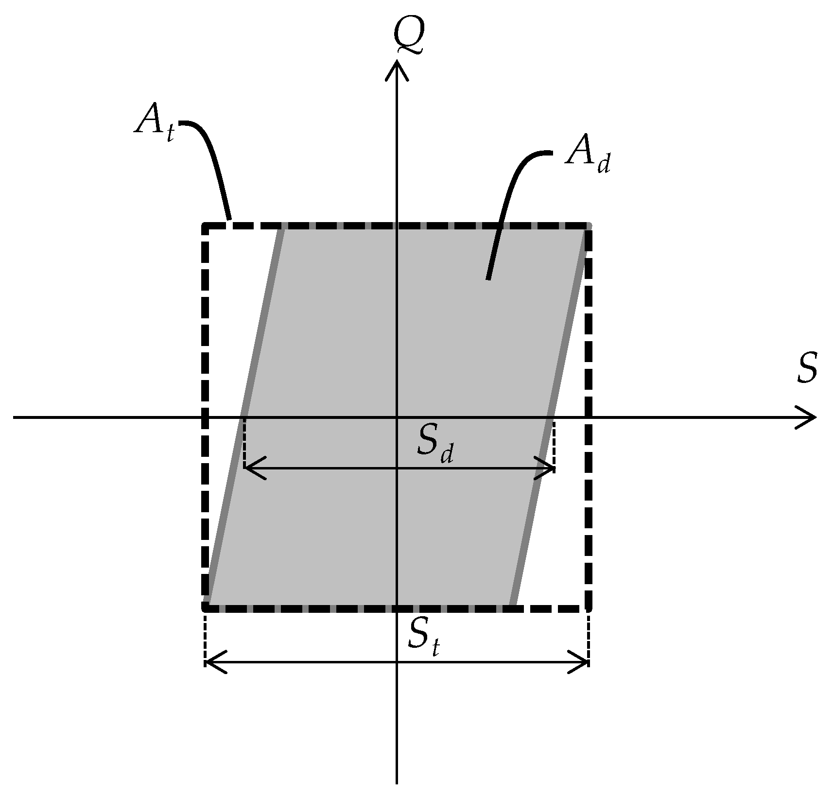
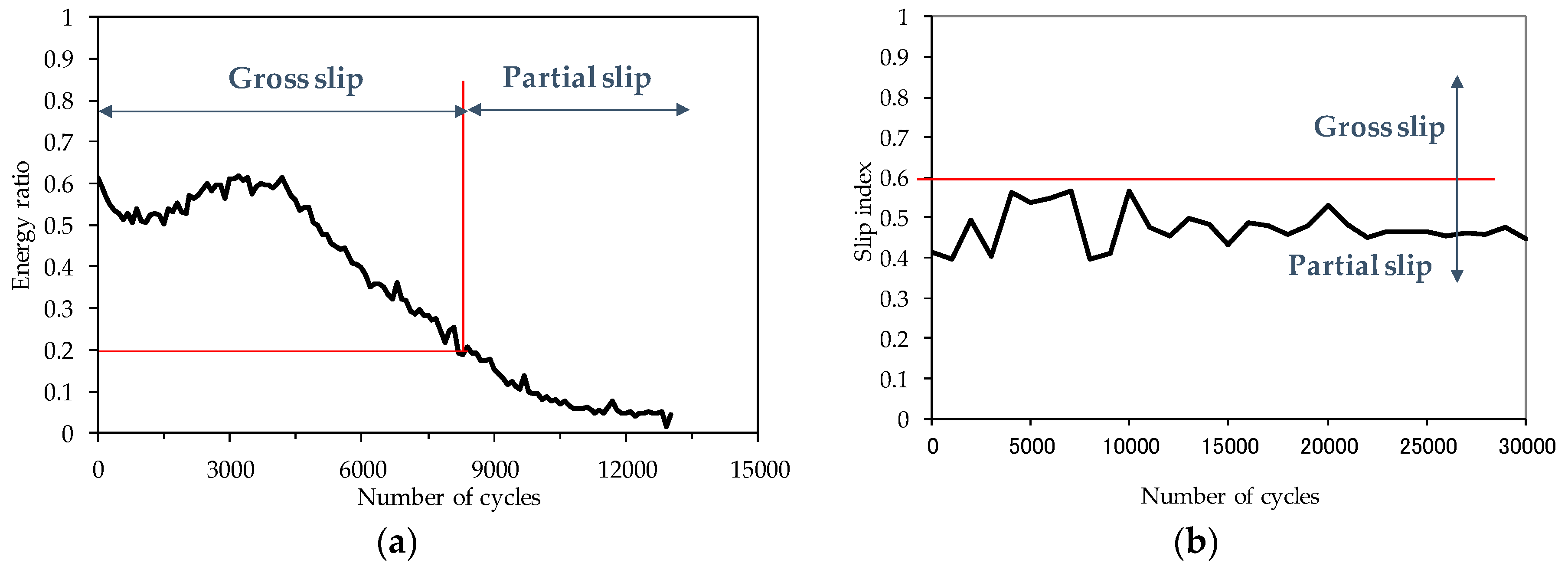
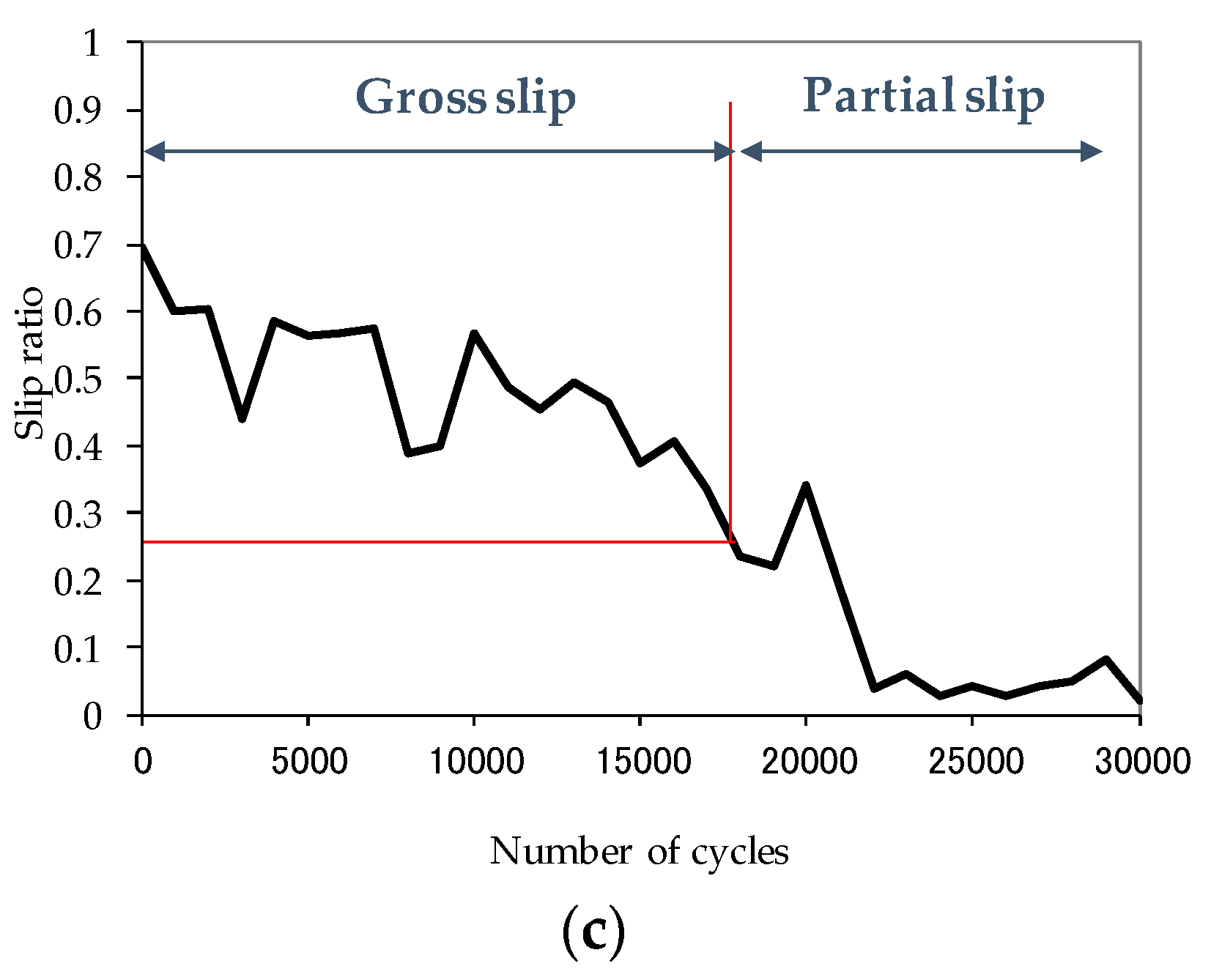
Figure 1. Schematic illustration of a running condition fretting map in terms of contact load and displacement amplitude, redrawn with permission from [2,5].
Coatings 09 00501 g001
Figure 2. Experimental fretting conditions found in various industries: (a) Factors determining fretting; (b) Conditions found in various components. f and S0 denote frequency and an imposed relative displacement, respectively.
Coatings 09 00501 g002
Figure 3. Typical rigs for a fretting wear test: (a) A cantilever-beam type; (b) An in-line type.
Coatings 09 00501 g003
Figure 4. Test termination of a fretting test with a coated system. Nf can be defined as the durability of a coated system.
Coatings 09 00501 g004
Figure 5. Wear rate according to displacement amplitude. Redrawn with permission from [2].
Coatings 09 00501 g005
Figure 6. Fretting loop. Q and S denote a tangential force and a relative displacement, respectively. At and Ad present total energy and dissipated energy. St and Sd mean total displacement and actual sliding distance, respectively.
Coatings 09 00501 g006
Figure 7. Changes of parameters of dry film lubricants during a fretting test [24,25]: (a) Energy ratio; (b) Slip index; (c) Slip ratio.
Coatings 09 00501 g007aCoatings 09 00501 g007b
Figure 8. Kind of deposition of a low friction coating [19].
Coatings 09 00501 g008
Figure 9. A conventional thermally sprayed double layer coating for an aerospace component [25,26].
Coatings 09 00501 g009
Figure 10. Contact systems with: (a) Single layer coating; (b) Multi-layer coating; (c) Functionally graded material coating (FGM). P and Q stand for normal and tangential loads, respectively.
Coatings 09 00501 g010
Figure 11. Contact systems with a single coating layer: (a) Perfectly bonded interface; (b) Rested on substrate (receding contact).
Coatings 09 00501 g011
Figure 12. Flow chart for conventional wear simulation using the McColl’s approach [85].
Coatings 09 00501 g012
Table 1. Direct comparison of the parameters used for identification of slip regimes. P denote a normal force.
TermEnergy RatioSlip Index (δ)Slip Ratio
EquationAd/At Q S t P ( S t S d ) Sd/St
Transition from partial slip to gross slip0.200.60–0.800.26
Transition from gross slip to reciprocal slidingN/A11.000.95
Table 2. Example of anti-fretting coatings.
InterfaceBlade/Disc (Aerospace) [3,9]Fuel Rod/Support (Nuclear) [12,18]Electric Connectors (Automotive) [11,16,17]Hip Implants (Biomedical) [10,14]
Underlying materialTi-6Al-4VZircaloy 4BrassTitanium alloy
Cobalt-Chromium-Molybdenum
Deposition methodThermal sprayThermal sprayElectroplatingChemical electroplating
CoatingCuNiIn + MoS2TiNTin, Nickel, GoldHydroxyapatite
Surface treatmentShot peening,
grit blasting
Polishing

