Article

Electrical Conductivity Measurement of Transparent Conductive Films Based on Carbon Nanoparticles

1
Department of Energy and Mechanical Engineering, Graduate School, Gyeongsang National University, Cheondaegukchi-Gil 38, Tongyeong 53064, Korea
2
Department of Energy and Mechanical Engineering, Institute of Marine Industry, Gyeongsang National University, Cheondaegukchi-Gil 38, Tongyeong 53064, Korea
3
Training Ship Operation Center, College of Marine Science, Gyeongsang National University, Cheondaegukchi-Gil 38, Tongyeong 53064, Korea
*
Author to whom correspondence should be addressed.
Coatings 2019, 9(8), 499; https://doi.org/10.3390/coatings9080499
Submission received: 15 July 2019 / Revised: 30 July 2019 / Accepted: 6 August 2019 / Published: 7 August 2019

Abstract

:
Transparent conductive films are fundamental materials, currently used in several fields. Recently, due to their unique multifunctional properties, composite materials have started to be used in place of fluorine tin oxide and indium tin oxide in transparent conductive electrodes. However, the production of composite materials is still complicated and involves toxic chemicals. Through a simple and environmentally-friendly method, we synthesized new composite materials—conductive, transparent, and flexible films—that can be applied to the production of modern optoelectronic devices. An even dispersion of the nanoparticles was achieved by ultrasound excitation. Moreover, a series of morphological and structural investigations were conducted on the films by scanning and transmission electron microscopy, electrical conductivity, Raman spectroscopy, X-ray diffraction and testing their sheet resistance. The results indicated that the tested composite materials were ideal for film coating. The nanofluids containing multi-walled carbon nanotubes presented the highest electrical conductivity; nevertheless, all the composite nanofluids tended to have relatively high electrical conductivities. The flexible films with composite structures presented lower sheet resistances than those with single structures. Finally, the hybrid materials showed a higher transmittance.

1. Introduction

Transparent conductive films (TCFs) have been widely applied to various devices (e.g., touchscreen panels (TSP), liquid crystal displays, e-papers, thin-film type solar cells, flexible displays) [1,2,3,4,5,6]. TCFs possess both optical transparency and good electrical conductivity; hence, they have recently emerged as important materials in the optoelectronic field. Many types of TCFs exist nowadays; however, fluorine tin oxide (FTO) and indium tin oxide (ITO) have been the most commonly used, due to their high transparencies, electrical conductivities, and chemical stabilities [7,8,9,10,11,12]. Unfortunately, TCFs based on ITO have a relatively high cost (indium is a rare-earth resource), and TCFs based on FTO have structural defects (e.g., voids forming between the film and its substrate during deposition) that decrease their electrical conductivity. In order to overcome the manufacturing cost of these TCFs and the faults of FTO-based TCFs, many researches have investigated alternative materials to the conventional ITO and FTO [13,14].
Semi- and non-transparent conductive materials made from carbon nanotubes (CNTs), metallic nanostructures, graphene (GN), or their derivatives have been widely considered as feasible substitutes for ITO and FTO [15,16,17,18,19,20,21,22,23,24]. Among these, composite materials based on GN and Ag nanoparticles (AgNPs) or CNTs, characterized by outstanding chemical stability, have been investigated as the dominant candidates due to their unusual properties [25,26,27]. In fact, the structure of GN can be described as a two-dimensional extended honeycomb network containing sp2-hybridized carbon atoms [28] and is characterized by high electron mobility [29], excellent mechanical-chemical properties [30], and high thermal conductivity [31]. CNTs possess outstanding chemical, optical, electrical and mechanical properties [32,33,34,35,36]; moreover, AgNPs have been applied to many research fields (e.g., for antibacterial applications, to heat-transfer fluids, transparent conductive electrodes (TCEs), solar cells) due to their exceptional properties (e.g., high conductivity, transparency and a special plasmonic effect) [21,37,38,39]. Therefore, CNTs and AgNPs are very promising materials for TCFs.
With the aim of creating a transparent conductive thin film deposition, while avoiding high-cost, time-consuming, complicated processes that involve the use of toxic chemicals, some studies have researched the characteristics of single materials (i.e., GN, AgNPs, CNT) [40,41,42,43]. Other studies have instead focused on composites of these materials, with the aim of reaching novel synergistic properties. Such composite materials have in fact showed advantageous properties: high electrical conductivity, stability, and transparency [44,45,46,47,48]. The creation of a conductive film on a substrate, by drying a nanofluid containing GN, AgNPs and CNT nanoparticles, is quite challenging, requiring innovative solutions to reduce cost and time consumption, the use of toxic chemicals and the complicated process [49,50]. The main obstacle appears to be the tendency of GN, AgNPs and CNT nanoparticles to agglomerate in water, which is caused by their hydrophobic surfaces, used to coat nanoparticles on a substrate by drying a nanofluid.
In this study, we applied the wet grinding method in order to mitigate the agglomeration effect, and the ultrasonication method to ensure an even dispersion of the nanoparticles during the preparation of a nanofluid. The hybrid materials were synthesized in an aqueous solution using the pulse power wire evaporation (PWE) method [51] and then combined with flexible films by coating them with polyvinylidene fluoride (PVDF). The thickness of the films was adjusted by adding drops of hybrid material solution. Here, we also describe a simple procedure for the coating of CNTs or GN with AgNPs on flexible films. Several devices were used to characterize the morphology and structure of the final films.
The main investigation of this study was to evaluate the sheet resistances and the electrical conductivities of single-structure films. The composite TCFs had noticeably great characteristics compared to the TCF with a single material. In this paper, we discussed our results in view of the potential applications of these composite materials to the production of conductive films.

2. Materials and Methods
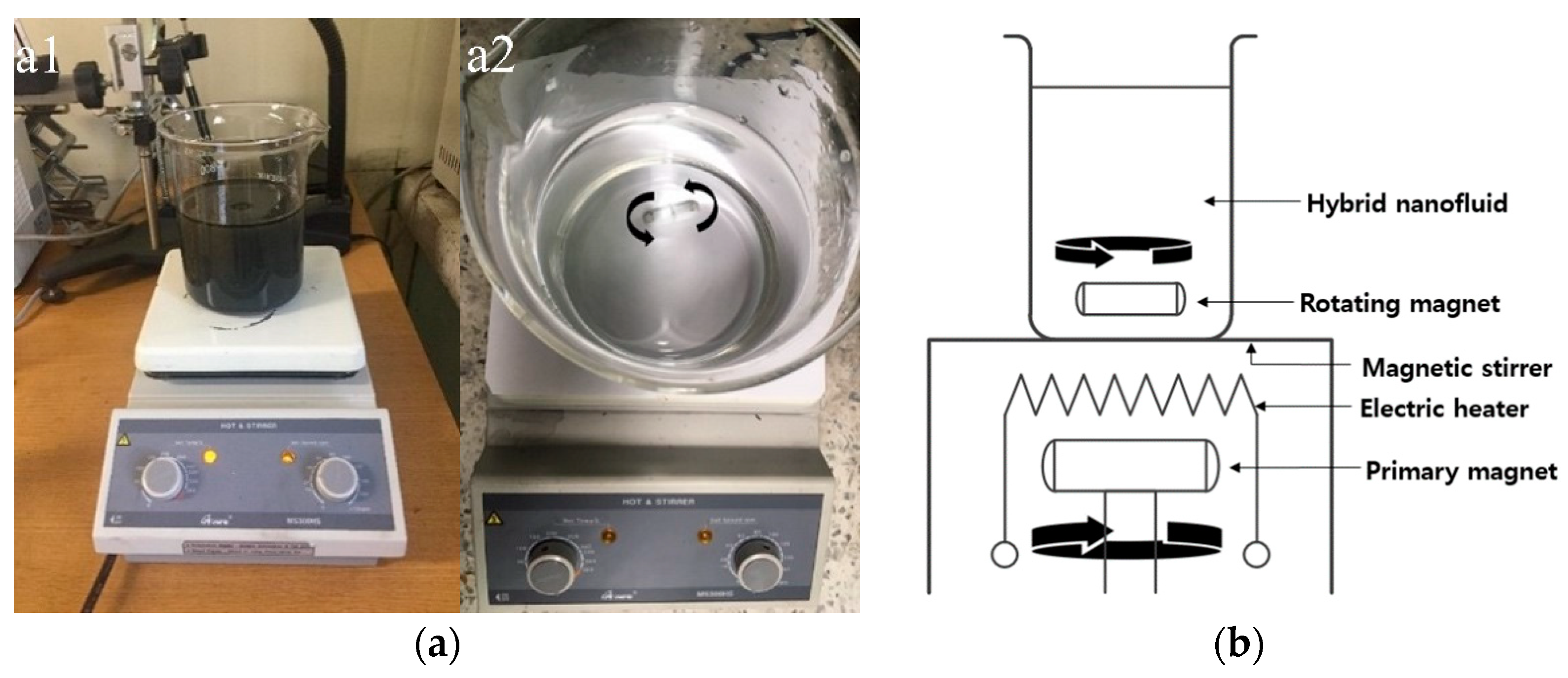
The transparent conductive film used in this study was prepared in the laboratory. The surface of the transparent film was made conductive through the following process: (1) the nanoparticles and the base liquid for the GN and multi-walled CNT (MWCNT) nanofluids were prepared; (2) the GN and MWCNT nanoparticles were grinded to increase their specific surface; (3) the nanofluids were prepared by separately mixing the GN and the MWCNT with a base fluid; (4) an Ag wire was evaporated through the PWE method (i.e., pulsed wire explosion); (5) the nanofluids containing AgNPs were completely evaporated to obtain well-distributed and well-mixed dried particles; (6) the obtained particles were dissolved in a N-methyl pyrrolidone (NMP) solution mixed with PVDF powder; (7) the NMP nanofluid was evenly dropped on the surface of a transparent film and left to dry naturally at room temperature. The following subsections describe in detail the process followed to prepare the transparent conductive film.

2.1. Nanofluid

The base liquid for the nanofluid was prepared using pure water. This water, obtained from a membrane-type pure water maker (RO 130, Rowafil, Venray, Netherlands), had <10 ppm of total dissolved solids (TDS). For the preparation of the GN nanofluid, a GN nanopowder (99.9% pure) was purchased from a USA GN supermarket. The nanopowder was composed of 8-nm flakes (20–30 monolayers), with an average lateral size of about 550 nm and a specific surface area of 100 m2/g. For the CNT nanofluid, we used raw MWCNT nanoparticles with diameters of 20 nm and lengths of ~5 μm, produced by Carbon Nanomaterial Technology Co., Ltd. (Gyongju, South Korea).
The nanopowder, supplied in a bottle, was partly agglomerated. We increased the specific area of the nanoparticles by grounding the nanopowder with a planetary ball milling (PBM) device (HPM-700, Haji Engineering, South Korea), before dispersing it in pure water. The nanopowder sample was ground at a grinding speed of 500 rpm under wet conditions for 1 h, employing mono-sized (3.0 mm) spherical zirconia (ZrO2) balls. This grinding method is an effective way for making a wide surface area, thereby significantly reducing the agglomeration of the nanopowder [52]. However, there is no need to describe the details of the grinding process because it can be referred to from many other studies [53,54].
To ensure an even dispersion of the ground nanoparticles within the base liquid, the nanofluid was processed with an ultrasonic exciter (Branson Ultrasonic Corporation 41, Danbury, CT, USA). Garg et al. [55] reported that the maximum thermal conductivity enhancement was obtained by applying ultrasonic excitation for 40 min; interestingly, the thermal conductivity of the nanofluid was decreased by prolonging the treatment over 40 min. In previous studies [53,54], the ground nanopowder was dispersed into pure water; then, in order to split the coalesced particles in the liquid, the resulting nanofluid was processed with an ultrasonic exciter for 40 min. Our hybrid nanofluid was instead prepared by mixing the base liquid, carbon particles, and metal particles, using an Ag wire with a diameter of 0.2 mm (Nano Technology Inc., Daejeon, South Korea). The AgNPs were dispersed into the previously prepared nanofluid through the PWE method, which can be used to achieve a homogeneous dispersion of nano-scaled particles in a liquid (Figure 1).
The PWE method was able to produce the nanofluid containing the nanosized metallic particles as follows: (1) a high-voltage direct current (DC) was supplied to a metal wire submerged in liquid; the metal wire was heated up and evaporated in a liquid; (2) the evaporated metallic particles were cooled and suspended in liquid metal [51]. As the PWE method requires low energy and does not produce by-products, it can be considered an eco-friendly process for the production of nanosized metallic particles uniformly distributed in a liquid.

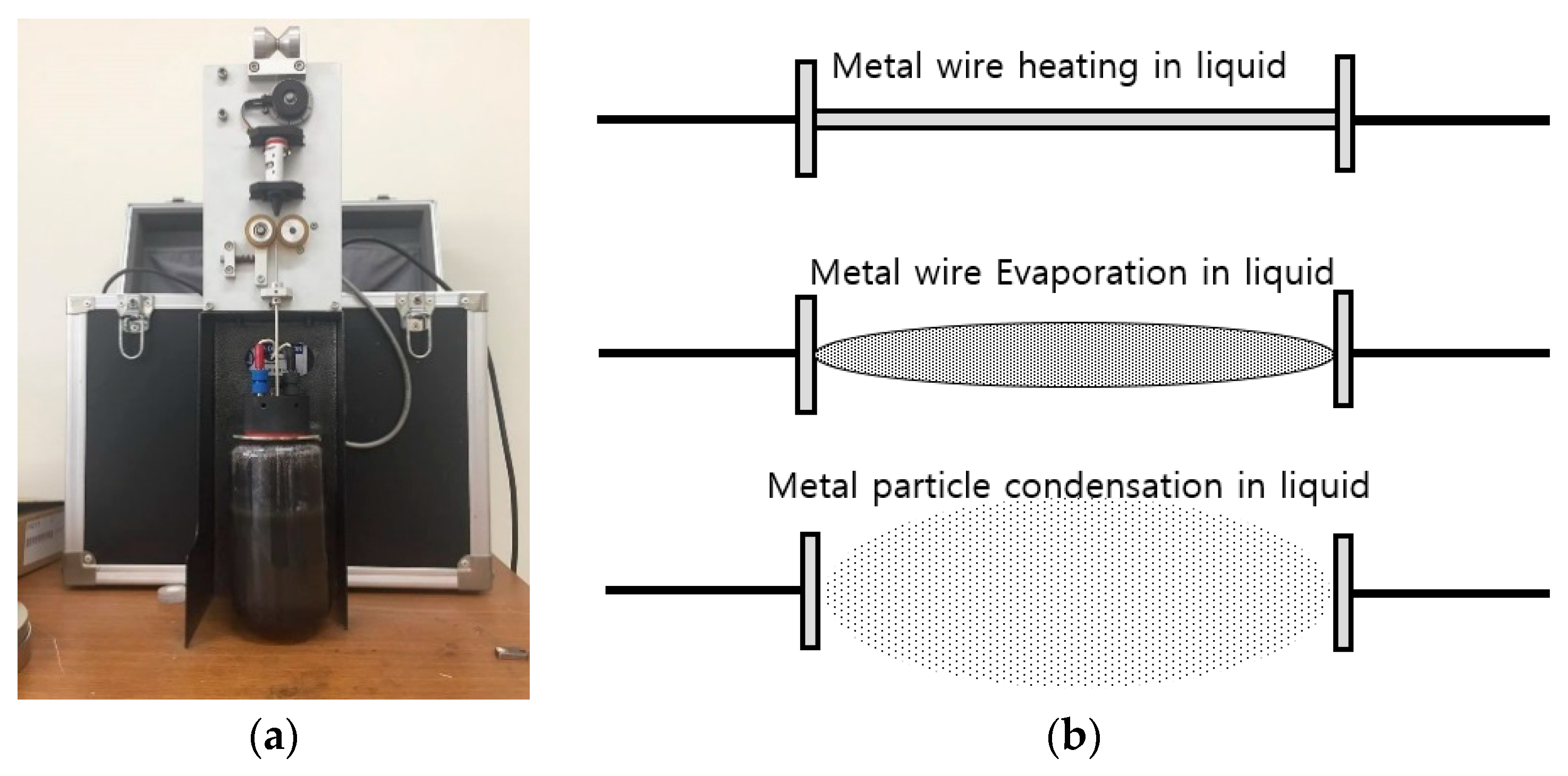
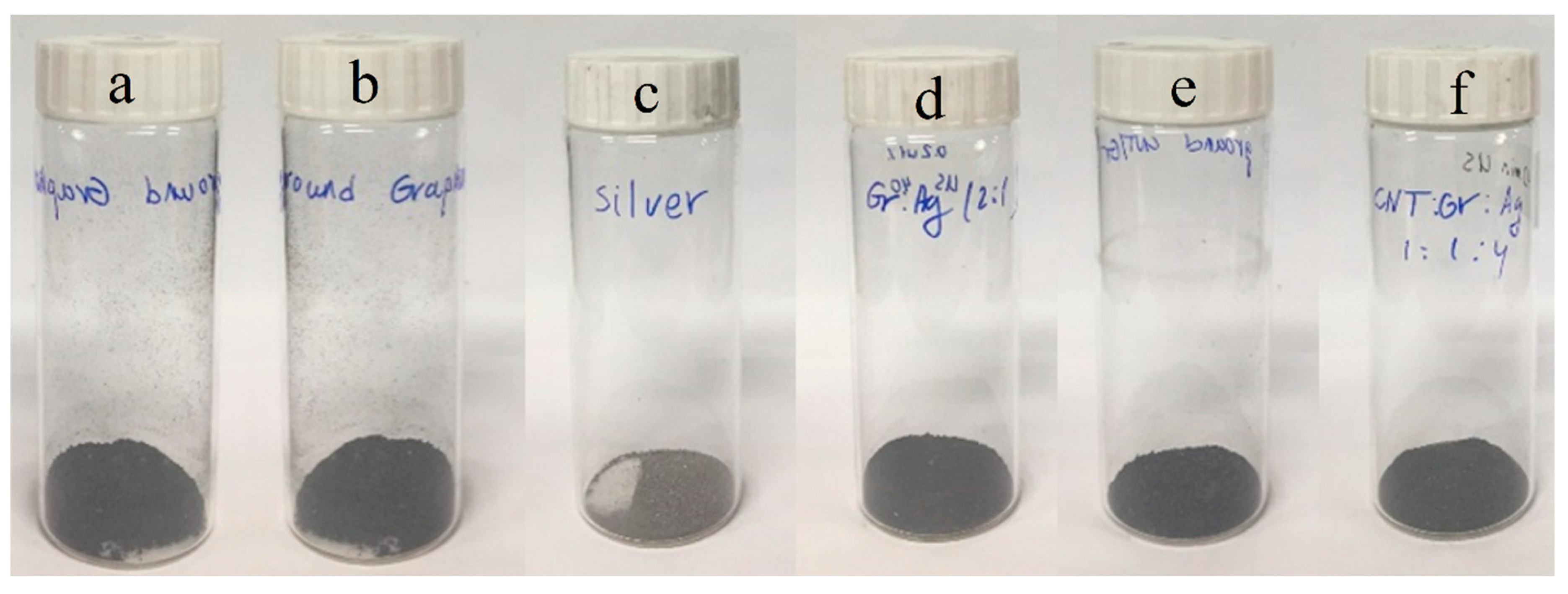
2.2. Hybrid Nanoparticles

For the hybrid nanofluid mixed with the carbon-based and Ag particles, the weight ratio of GN (or MWCNTs) and AgNPs (1:2) was adopted in accordance with a previous study [46], which described it as the ratio providing the highest TCF performance. The hybrid nanofluid was stirred to reduce the amount of water, while maintaining the homogeneous mixture of nanoparticles, using a magnetic stirrer (hot plate stirrer, SMSH-20A, Scilab Korea, Ltd., Seoul, South Korea).
As shown in the schematic diagram of Figure 2, the plate temperature of the magnetic stirrer was controlled by an electrical heater, which was installed inside the plate. After setting the plate temperature to ~60 °C and the magnet rotation velocity to 30 rpm, the drying process was completed in ~10 h. As Ag is a non-magnetic material, the AgNPs did not stick to the magnet during the drying process.
Most of the nanofluid water evaporated within 10 h and we obtained the wetted hybrid nanoparticles. The slow pace of the drying process prevented any agglomeration of the particles during water evaporation. Finally, the wetted nanoparticles were completely dried in an electrical furnace (Mulffle basic model, Dongwon Scientific Co., Seoul, South Korea) set at 250 °C for 30 min. Figure 3 shows a photo of the dried nanoparticles.

2.3. Conductive Transparent Film

To bond the nanoparticles on the transparent film, we used the PVDF powder as a binder: this is a polymeric material characterized by high thermal and electrochemical stabilities, as well as good adhesive strength. To be used as the adhesive for nanoparticles, the PVDF powder should be dissolved into a solvent and then well mixed with the nanoparticles. In this study, we first mixed the nanoparticles with the NMP solvent and then added the PVDF powder into the solvent, as the NMP solution was hydrophilic and well mixed with water [56].
To prepare the conductive transparent film, a flexible polyethylene terephthalate (PET) film was submerged into liquid ethanol and subjected to ultrasonication for 20 min. Afterward, the PET film was dried in a furnace at 50 °C in order to remove any potential surface contamination. The cleaned film was then decorated by an appropriate number of drops for each prepared nanofluid sample. The drop number (1 mg/mL) was used for the evaluation of the thickness of the composites. The decorated PET films were finally dried at room temperature.
According to Wen et al. [57], embedding of AgNPs to the nanoparticles significantly improved their homogeneous dispersion and reduced their agglomeration by increasing the distance between pristine nanoparticles. The improved dispersion of the nanoparticles was confirmed through transmission electron microscopy (TEM, JEM-2100 F, JEOL, Tokyo, Japan) observations.
The morphological structures of the dried nanoparticles are shown in TEM micrographs in Figure 4. Panels a and b show the pristine GNs and MWCNTs, respectively, while panel c shows the AgNPs (produced in pure water using the PWE method, and then dried). Panels d–f show the AgNPs attached to GN, MWCNT, and hybrid nanoparticles, respectively. By comparing these latter panels with panel c, it appears that the AgNPs were well attached to the other three types of nanoparticles.

2.4. Characterization

The structural characteristics were assessed with an X-ray diffractometer (XRD, D8 Advance powder diffractometer, Bruker AXS, Billerica, MA, USA), using a Cu Kα radiation of λ = 1.5406 Å of 10o to 90o. Moreover, the defects of GN and MWCNTs after the introduction of the AgNPs were analyzed with a Raman spectrometer (Labram HR800 (Horiba France SAS, Longjumeau, France) installed at the Central Research Facilities of Gyeongsang National University (Chinju, Korea)), using a 514-nm argon-ion laser (ranging between 1200–1800 cm−1), The transmittance and sheet resistance of the samples were instead measured using an UV (ultraviolet) spectrophotometer (X-ma 3000 Series Spectrophotometer, Human Co., Ltd., Busan, Korea) and a sheet resistance measurement system (CMT-SR1000N, AIT Co., Ltd., Suwon, Korea). For all the measurements, tests were recorded within three days and each was carried out three times in the same way. However, no significant difference was found in any experiment.

3. Results and Discussion

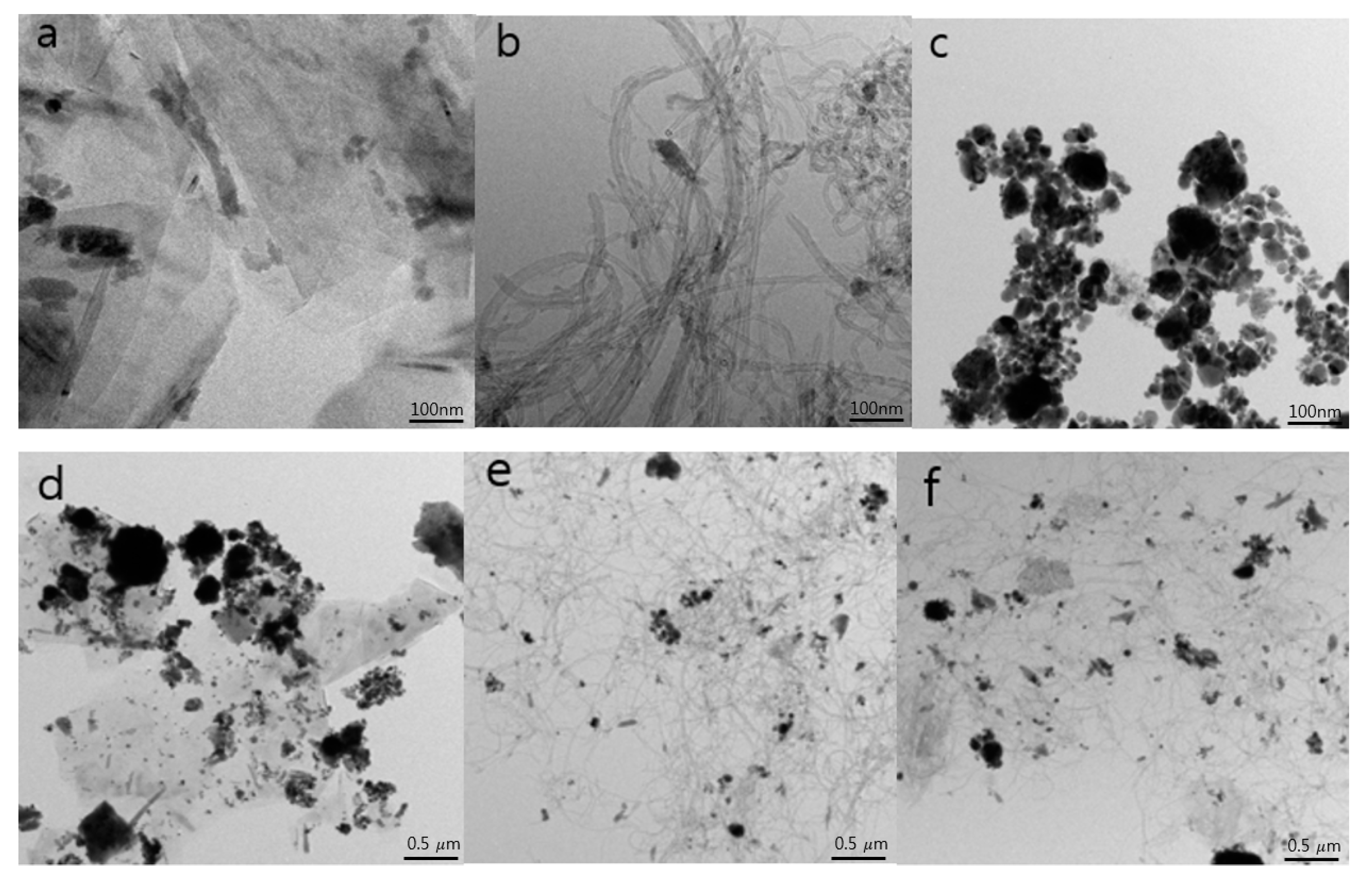
3.1. Morphological Surface Analysis of the MWCNTs

The XRD patterns of the pristine GN, AgNPs, MWCNT and of their hybrids, are displayed in Figure 5. The crystalline plane peaks (002), (101), (004), (110) and (112) of GN were depicted at 2θ = 26.5°, 44.6°, 54.6°, 77.6° and 83.8° in the XRD pattern of the pristine GN, respectively [53], while the crystalline plane peaks (002) and (100) of the MWCNTs were depicted at 2θ = 25° and 43° [57,58]. In addition, the crystalline plane peaks (110), (200), (220), (311) and (222) of the AgNPs were identified at 2θ = 38.3°, 44.4°, 63.5°, 77.7° and 81.6°, respectively [59,60]. Apparently, all the crystalline plane peaks of the single-structure surfaces were identified in the XRD pattern of their hybrid; furthermore, the AgNPs were successfully associated with the single-structure surfaces.
Raman spectroscopy has historically played an important role in defining the structural characteristics (e.g., qualities, structural defects) of graphitic materials. Moreover, it has become a useful tool to understand the behavior of electrons and phonons in GN and to better understand GN in general [61,62,63,64]. We performed Raman spectroscopy measurements to confirm the results of the XRD measurements. The main peaks of graphite (i.e., D and G) were observed at ~1350 and 1580 cm−1 in the Raman spectra of all composites (Figure 6), indicating that the single-structure surfaces were synthesized successfully. The assignment of the D and G peaks was straightforward in the “molecular” picture of the carbon materials. The intensity ratio of the D and G bands (ID/IG) is usually considered to identify structural defects and purity [64]. These two bands are present in all poly-aromatic hydrocarbons [65]: the G peak derives from the bond stretching between all pairs of sp2 atoms (disposed in rings and chains), while the D peak derives from the breathing modes of sp2 atoms (disposed in rings) [66]. The ID/IG intensity for the pristine GN was equal to 0.53, while for the MWCNTs it was 0.93. Furthermore, the ID/IG intensities for the GN-AgNPs, MWCNTs-AgNPs and GN-MWCNTs-AgNPs were 0.87, 1.11 and 0.98, respectively, and they increased compared to those of the respective single-structure materials, due to some structural changes (e.g., local defects, disorders).

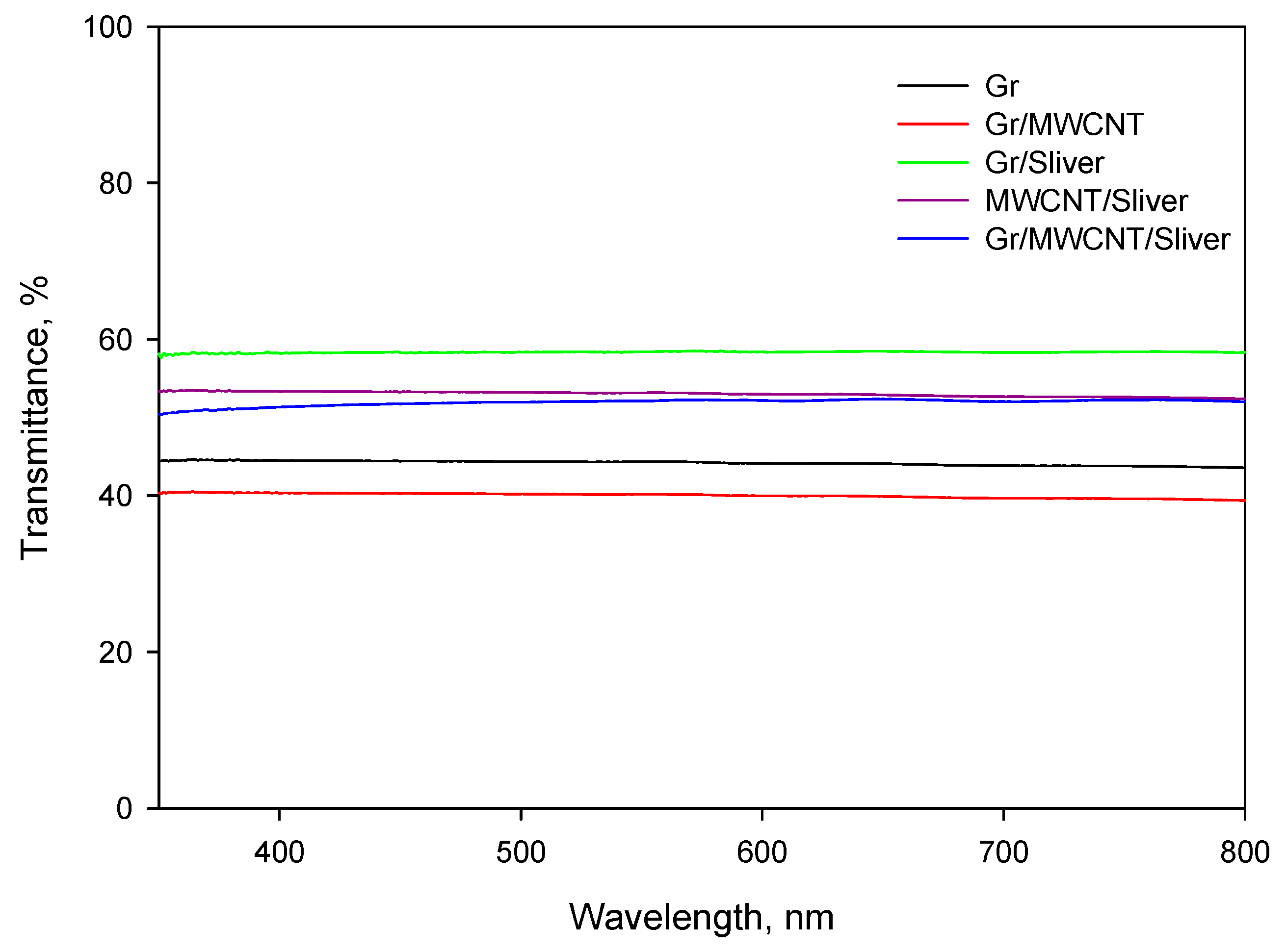
3.2. Material Transmittance

The transmittance of the films was investigated using a UV/VIS (UV–visible) spectrophotometer. This spectrophotometer provides information on the transparency of films in relation to different wavelengths. It is capable of analyzing a wide range of wavelengths (190–1100 nm) and photometric (−0.3 to 3.0 A/0 to 9999 C) ranges; moreover, it has a high photometric accuracy and repeatability. The transmittance results are shown in Figure 7. After the introduction of the AgNPs, we recorded mostly higher transmittance values. Therefore, it seems that the transparent film with AgNPs was successfully applied to the TCF.

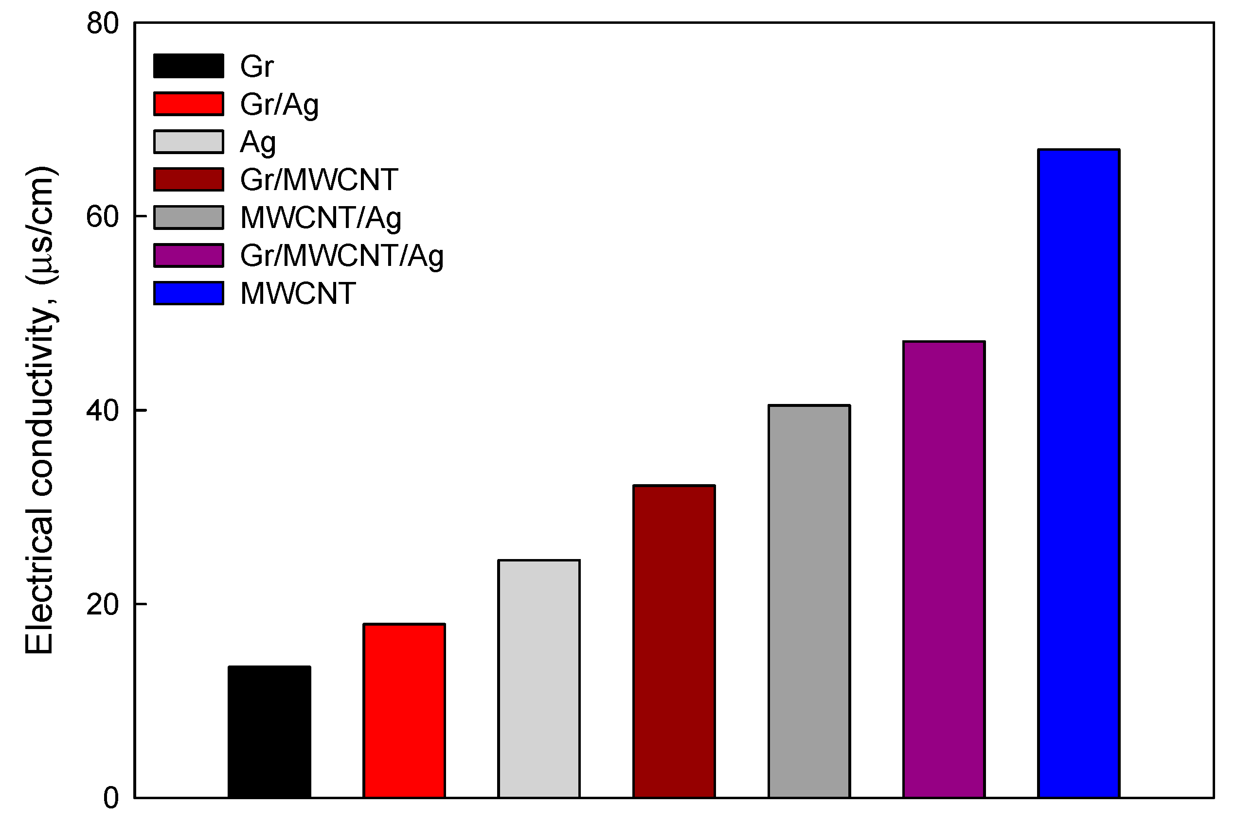
3.3. Electrical Conductivity

Electrical conductivity is a unique property for electromechanical and microelectronic devices. In this study, we tested the electrical conductivity of the fluids with nanoparticles. Before the measurement, we performed a calibration using standard potassium chloride solutions (1.41 and 12.86 μS/cm, respectively). Figure 8 shows the electrical conductivity of the nanofluids at a concentration of 0.1 wt.% for each sample. The nanofluids containing MWCNTs presented the highest electrical conductivities; additionally, the electrical conductivities of the composites containing AgNPs were higher than those of the single GN and AgNP solutions. Overall, the hybrid materials tend to have good electrical conductivities.

3.4. Sheet Resistance Performance

Following the results described in the previous section, we investigated the possible practical applications for sheet resistance performance. The sheet resistances of the samples were compared and the TCF thickness was adjusted considering the same drop number. The hybrid films containing Ag showed remarkably lower sheet resistances than the other films (Table 1). Overall, the hybrid films generally demonstrated high transparency and electrical conductivity.

4. Conclusions

Because the applications of transparent conductive films to IT technologies are rapidly expanding, improving their performance is very important and urgently required. In this experimental study, we aimed at increasing the electrical conductivity of a transparent conductive film by applying AgNPs, as well as the single nanoparticle structures of GN, MWCNT, and their hybrid (GN + MWCNT). The functional performances of the combined nanoparticle structures containing AgNPs were compared to those of the pristine films based on their electrical conductivities, sheet resistances, and transmittances. Additionally, we evaluated the morphological and structural characteristics of the composite materials. As mentioned in Section 2, the preparation of our test specimens was conducted by applying a simple, environmentally-friendly, and convenient method.
The XRD and Raman spectra analyses confirmed that the AgNPs were well integrated into the single and hybrid nanostructures. The electrical conductivity measurements indicated that the hybrid fluid containing AgNPs had a higher electrical conductivity than the other solutions, while it has a lower electrical conductivity than the pristine MWCNT solution. Additionally, we demonstrated that the GN film containing AgNPs had the highest transmittance (~60%).
Both the electrical conductivity and transmittance of the carbon thin film were improved by introducing AgNPs (Figure 7 and Figure 8). Because a transparent conductive film should possess both high electrical conductivity and transmittance, these two characteristics should not be traded off. Our experimental study demonstrated that the tested hybrid films, containing AgNPs, presented the highest electrical conductivity and transmittance (~50%). Notably, this study was carried out using only one mass ratio of AgNPs; therefore, the performances of these hybrid films might be improved by changing the AgNP ratio.

Author Contributions

Conceptualization, S.K. and J.-T.P.; Data Curation, S.K.; Formal Analysis, H.J. and J.-T.P.; Methodology, H.J. and S.-H.C.; Investigation, S.K.; Validation, S.-H.C.; Writing–Original Draft Preparation, S.K.; Writing–Review and Editing, H.J. and J.-T.P.

Funding

This research was supported by Basic Science Research Program through the National Research Foundation of Korea (NRF) funded by the Ministry of Science, ICT and future Planning (No. 2017R1A2B4007620).

Conflicts of Interest

This manuscript has not been published or presented elsewhere in part or in entirety and is not under consideration by another journal. We have read and understood your journal’s policies, and we believe that neither the manuscript nor the study violates any of these. There are no conflicts of interest to declare.

References

  1. Kwak, K.; Cho, K.; Kim, S. Stable bending performance of flexible organic light-emitting diodes using IZO anodes. Sci. Rep. 2013, 3, 2787. [Google Scholar] [CrossRef] [PubMed]
  2. Chen, S.; Deng, L.; Xie, J.; Peng, L.; Xie, L.; Fan, Q.; Huang, W. Recent developments in top-emitting organic light-emitting diodes. Adv. Mater. 2010, 22, 5227–5239. [Google Scholar] [CrossRef] [PubMed]
  3. Fu, W.; Liu, L.; Jiang, K.; Li, Q.; Fan, S. Super-aligned carbon nanotube films as aligning layers and transparent electrodes for liquid crystal displays. Carbon 2010, 48, 1876–1879. [Google Scholar] [CrossRef]
  4. Kim, S.; Dovjuu, O.; Choi, S.H.; Jeong, H.; Park, J.T. Photovoltaic characteristics of multiwalled carbon nanotube counter-electrode materials for dye-sensitized solar cells produced by chemical treatment and addition of dispersant. Coatings 2019, 9, 250. [Google Scholar] [CrossRef]
  5. Hu, Z.; Zhang, J.; Hao, Z.; Hao, Q.; Geng, X.; Zhao, Y. Highly efficient organic photovoltaic devices using F-doped SnO2 anodes. Appl. Phys. Lett. 2011, 98, 123302. [Google Scholar] [CrossRef]
  6. Granqvist, C.G. Transparent conductors as solar energy materials: A panoramic review. Sol. Energy Mater. Sol. Cells 2007, 91, 1529–1598. [Google Scholar] [CrossRef]
  7. Minami, T. Present status of transparent conducting oxide thin-film development for indium-tin-oxide (ITO) substitutes. Thin Solid Films 2008, 516, 5822–5828. [Google Scholar] [CrossRef]
  8. Hammad, T.M. Effect of annealing on electrical, structural and optical properties of sol-gel ITO thin films. Phys. Status Solidi A 2009, 206, 2128–2132. [Google Scholar] [CrossRef]
  9. Lewis, B.G.; Paine, D.C. Applications and processing of transparent conducting oxides. MRS Bull. 2000, 25, 22–27. [Google Scholar] [CrossRef]
  10. Lee, J.; Lee, S.; Li, G.; Petruska, M.A.; Paine, D.C.; Sun, S. A facile solution-phase approach to transparent and conducting ITO nanocrystal assemblies. J. Am. Chem. Soc. 2012, 134, 13410–13414. [Google Scholar] [CrossRef]
  11. Wu, H.; Hu, L.; Carney, T.; Ruan, Z.; Kong, D.; Yu, Z.; Yao, Y.; Cha, J.J.; Zhu, J.; Fan, S.; et al. Low reflectivity and high flexibility of tin doped indium oxide nanofiber transparent electrodes. J. Am. Chem. Soc. 2011, 133, 27–29. [Google Scholar] [CrossRef] [PubMed]
  12. Andersson, A.; Johansson, N.; Bröms, P.; Yu, N.; Lupo, D.; Salaneck, W.R. Fluorine tin oxide as an alternative to indium tin oxide in polymer LEDs. Adv. Mater. 1998, 10, 859–863. [Google Scholar] [CrossRef]
  13. Hecht, D.S.; Hu, L.; Irvin, G. Emerging transparent electrodes based on thin films of carbon nanotubes, graphene, and metallic nanostructures. Adv. Mater. 2011, 23, 1482–1513. [Google Scholar] [CrossRef] [PubMed]
  14. Rizo, H.V.; Gullon, I.M.; Terrones, M. Hybrid films with graphene oxide and metal nanoparticles could now replace indium tin oxide. ACS Nano 2012, 6, 4565–4572. [Google Scholar] [CrossRef] [PubMed]
  15. Wu, Z.; Chen, Z.; Du, X.; Logan, J.M.; Sippel, J.; Nikolou, M.; Kamaras, K.; Reynolds, J.R.; Tanner, D.B.; Hebard, A.F.; et al. Transparent, conductive carbon nanotube films. Science 2004, 305, 1273–1276. [Google Scholar] [CrossRef] [PubMed]
  16. Park, S.; Vosguerichian, M.; Bao, Z. A review of fabrication and applications of carbon nanotube film-based flexible electronics. Nanoscale 2013, 5, 1727–1752. [Google Scholar] [CrossRef] [PubMed]
  17. Kim, K.S.; Zhao, Y.; Jang, H.; Lee, S.Y.; Kim, J.M.; Kim, K.S.; Ahn, J.H.; Kim, P.; Choi, J.Y.; Hong, B.H. Large-scale pattern growth of graphene films for stretchable transparent electrodes. Nature 2009, 457, 706–710. [Google Scholar] [CrossRef] [PubMed]
  18. Wassei, J.K.; Kaner, R.B. Graphene, a promising transparent conductor. Mater. Today 2010, 13, 52–59. [Google Scholar] [CrossRef]
  19. Zheng, Q.; Li, Z.; Yang, J.; Kim, J.K. Graphene oxide-based transparent conductive films. Prog. Mater. Sci. 2014, 64, 200–247. [Google Scholar] [CrossRef]
  20. Zhang, D.; Wang, R.; Wen, M.; Weng, D.; Cui, X.; Sun, J.; Li, H.; Lu, Y. Synthesis of ultralong copper nanowires for high-performance transparent electrodes. J. Am. Chem. Soc. 2012, 134, 14283–14286. [Google Scholar] [CrossRef]
  21. Hu, L.; Kim, H.S.; Lee, J.Y.; Peumans, P.; Cui, Y. Scalable coating and properties of transparent, flexible, silver nanowire electrodes. ACS Nano 2010, 4, 2955–2963. [Google Scholar] [CrossRef] [PubMed]
  22. Chun, K.Y.; Oh, Y.; Rho, J.; Ahn, J.H.; Kim, Y.J.; Choi, H.R.; Baik, S. Highly conductive, printable and stretchable composite films of carbon nanotubes and silver. Nat. Nanotechnol. 2010, 5, 853–857. [Google Scholar] [CrossRef] [PubMed]
  23. Tung, V.C.; Chen, L.M.; Allen, M.J.; Wassei, J.K.; Nelson, K.; Kaner, R.B.; Yang, Y. Low-temperature solution processing of graphene-carbon nanotube hybrid materials for high-performance transparent conductors. Nano Lett. 2009, 9, 1949–1955. [Google Scholar] [CrossRef] [PubMed]
  24. Watcharotone, S.; Dikin, D.A.; Stankovich, S.; Piner, R.; Jung, I.; Dommett, G.H.B.; Evmenenko, G.; Wu, S.E.; Chen, S.F.; Liu, C.P. Graphene-silica composite thin films as transparent conductors. Nano Lett. 2007, 7, 1888–1892. [Google Scholar] [CrossRef] [PubMed]
  25. Lee, D.; Lee, H.; Ahn, Y.; Jeong, Y.; Lee, D.Y.; Lee, Y. Highly stable and flexible silver nanowire-graphene hybrid transparent conducting electrodes for emerging optoelectronic devices. Nanoscale 2013, 5, 7750–7755. [Google Scholar] [CrossRef] [PubMed]
  26. Liu, Y.; Chang, Q.; Huang, L. Transparent, flexible conducting graphene hybrid films with a subpercolating network of silver nanowires. J. Mater. Chem. C 2013, 1, 2970–2974. [Google Scholar] [CrossRef]
  27. Li, Z.; Kandel, H.R.; Dervishi, E.; Saini, V.; Xu, Y.; Biris, A.R.; Lupu, D.; Salamo, G.J.; Biris, A.S. Comparative study on different carbon nanotube materials in terms of transparent conductive coatings. Langmuir 2008, 24, 2655–2662. [Google Scholar] [CrossRef] [PubMed]
  28. Pereg-Barnea, T.; Refael, G. Inducing topological order in a honeycomb lattice. Phys. Rev. B 2010, 85, 075127. [Google Scholar] [CrossRef]
  29. Bolotin, K.I.; Sikes, K.J.; Jiang, Z.; Klima, M.; Fudenberg, G.; Hone, J.; Kim, P.; Stormer, H.L. Ultrahigh electron mobility in suspended graphene. Solid State Commun. 2008, 146, 351–355. [Google Scholar] [CrossRef] [Green Version]
  30. Lee, C.; Wei, X.; Kysar, J.W.; Hone, J. Measurement of the elastic properties and intrinsic strength of monolayer graphene. Science 2008, 321, 385–388. [Google Scholar] [CrossRef] [PubMed]
  31. Balandin, A.A.; Ghosh, S.; Bao, W.; Calizo, I.; Teweldebrhan, D.; Miao, F.; Lau, C.N. Superior thermal conductivity of single-layer graphene. Nano Lett. 2008, 8, 902–907. [Google Scholar] [CrossRef]
  32. Pop, E.; Mann, D.; Wang, Q.; Goodson, K.; Dai, H. Thermal conductance of an individual single-wall carbon nanotube above room temperature. Nano Lett. 2006, 6, 96–100. [Google Scholar] [CrossRef] [PubMed]
  33. Zhang, X.; Li, Q.; Holesinger, T.G.; Arendt, P.N.; Huang, J.; Kirven, P.D.; Clapp, T.G.; DePaula, R.F.; Liao, X.; Zhao, Y.; et al. Ultrastrong, stiff, and lightweight carbon-nanotube fibers. Adv. Mater. 2007, 19, 4198–4201. [Google Scholar] [CrossRef]
  34. Inam, F.; Heaton, A.; Brown, P.; Peijs, T.; Reece, M.J. Effects of dispersion surfactants on the properties of ceramic-carbon nanotube (CNT) nanocomposites. Ceram. Int. 2014, 40, 511–516. [Google Scholar] [CrossRef]
  35. Tawfick, S.; O’brien, K.; Hart, A.J. Flexible high-conductivity carbon-nanotube interconnects made by rolling and printing. Small 2009, 5, 2467–2473. [Google Scholar] [CrossRef] [PubMed]
  36. Berber, S.; Kwon, Y.K.; Tománek, D. Unusually high thermal conductivity of carbon nanotubes. Phys. Rev. Lett. 2000, 84, 4613. [Google Scholar] [CrossRef] [PubMed]
  37. Batmunkh, M.; Tanshen, M.R.; Nine, M.J.; Myekhlai, M.; Choi, H.; Chung, H.; Jeong, H. Thermal conductivity of TiO2 nanoparticles based aqueous nanofluids with an addition of a modified silver particle. Ind. Eng. Chem. Res. 2014, 53, 8445–8451. [Google Scholar] [CrossRef]
  38. Becker, J.; Zins, I.; Jakab, A.; Khalavka, Y.; Schubert, O.; Sönnichsen, C. Plasmonic focusing reduces ensemble line width of silver-coated gold nanorods. Nano Lett. 2008, 8, 1719–1723. [Google Scholar] [CrossRef] [PubMed]
  39. Chen, X.; Jia, B.; Saha, J.K.; Cai, B.; Stokes, N.; Qiao, Q.; Wang, Y.; Shi, Z.; Gu, M. Broadband enhancement in thin-film amorphous silicon solar cells enabled by nucleated silver nanoparticles. Nano Lett. 2012, 12, 2187–2192. [Google Scholar] [CrossRef]
  40. Kholmanov, I.N.; Magnuson, C.W.; Aliev, A.E.; Li, H.; Zhang, B.; Suk, J.W.; Zhang, L.L.; Peng, E.; Mousavi, S.H.; Khanikaev, A.B.; et al. Improved electrical conductivity of graphene films integrated with metal nanowires. Nano Lett. 2012, 12, 5679–5683. [Google Scholar] [CrossRef]
  41. Lee, J.; Novoselov, K.S.; Shin, H.S. Interaction between metal and graphene: Dependence on the layer number of graphene. ACS Nano 2011, 5, 608–611. [Google Scholar] [CrossRef] [PubMed]
  42. Pasricha, R.; Gupta, S.; Srivastava, A.K. A facile and novel synthesis of Ag-graphene-based nanocomposites. Small 2009, 5, 2253–2259. [Google Scholar] [CrossRef] [PubMed]
  43. Zhang, Z.; Xu, F.; Yang, W.; Guo, M.; Wang, X.; Zhang, B.; Tang, J. A facile one-pot method to high-quality Ag-graphene composite nanosheets for efficient surface-enhanced Raman scattering. Chem. Commun. 2011, 47, 6440–6442. [Google Scholar] [CrossRef] [PubMed]
  44. Kholmanov, I.N.; Stoller, M.D.; Edgeworth, J.; Lee, W.H.; Li, H.; Lee, J.; Barnhart, C.; Potts, J.R.; Piner, R.; Akinwande, D.; et al. Nanostructured hybrid transparent conductive films with antibacterial properties. ACS Nano 2012, 6, 5157–5163. [Google Scholar] [CrossRef] [PubMed]
  45. Chen, R.; Das, S.R.; Jeong, C.; Khan, M.R.; Janes, D.B.; Alam, M.A. Co-percolating graphene-wrapped silver nanowire network for high performance, highly stable, transparent conducting electrodes. Adv. Funct. Mater. 2013, 23, 5150–5158. [Google Scholar] [CrossRef]
  46. Tien, H.W.; Huang, Y.L.; Yang, S.Y.; Wang, J.; Ma, C.M. The production of graphene nanosheets decorated with silver nanoparticles for use in transparent, conductive films. Carbon 2011, 49, 1550–1560. [Google Scholar] [CrossRef]
  47. Li, J.; Liu, C.Y. Ag/graphene heterostructures: Synthesis, characterization and optical properties. Eur. J. Inorg. Chem. 2010, 8, 1244–1248. [Google Scholar] [CrossRef]
  48. He, F.A.; Fan, J.T.; Song, F.; Zhang, L.M.; Chan, H.L.W. Fabrication of hybrids based on graphene and metal nanoparticles by in situ and self-assembled methods. Nanoscale 2011, 3, 1182–1188. [Google Scholar] [CrossRef]
  49. Woltornist, S.J.; Oyer, A.J.; Carrillo, J.M.Y.; Dobrynin, A.V.; Adamson, D.H. Conductive thin films of pristine graphene by solvent interface trapping. ACS Nano 2013, 7, 7062–7066. [Google Scholar] [CrossRef]
  50. Munkhbayar, B.; Hwang, S.; Kim, J.; Bae, K.; Ji, M.; Chung, H.; Jeong, H. Photovoltaic performance of dye-sensitized solar cells with various MWCNT counter electrode structures produced by different coating methods. Electrochim. Acta 2012, 80, 100–107. [Google Scholar] [CrossRef]
  51. Uhm, Y.R.; Park, J.H.; Kim, W.W.; Cho, C.H.; Rhee, C.K. Magnetic properties of nano-size Ni synthesized by the pulsed wire evaporation (PWE) method. Mater. Sci. Eng. 2004, 106, 224–227. [Google Scholar] [CrossRef]
  52. Lee, J.H.; Rhee, K.Y.; Park, S.J. Effects of cryomilling on the structures and hydrogen storage characteristics of multi-walled carbon nanotubes. Int. J. Hydrogen Energ. 2010, 35, 7850–7857. [Google Scholar] [CrossRef]
  53. Myekhlai, M.; Munkhbayar, B.; Lee, T.; Tanshen, M.R.; Chung, H.; Jeong, H. Experimental investigation of the mechanical grinding effect on graphene structure. RSC Adv. 2014, 4, 2495–2500. [Google Scholar] [CrossRef]
  54. Munkhbayar, B.; Nine, M.J.; Jeoun, J.; Bat-Erdene, M.; Chung, H.; Jeong, H. Influence of dry and wet ball milling on dispersion characteristics of the multi-walled carbon nanotubes in aqueous solution with and without surfactant. Powder Technol. 2013, 234, 132–140. [Google Scholar] [CrossRef]
  55. Garg, P.; Alvarado, J.L.; Marsh, C.; Carlson, T.A.; Kessler, D.A.; Annamalai, K. An experimental study on the effect of ultrasonication on viscosity and heat transfer performance of multi-wall carbon nanotube-based aqueous nanofluids. Int. J. Heat Mass Tran. 2009, 52, 5090–5101. [Google Scholar] [CrossRef]
  56. Wong, S.S.; Joselevich, E.; Woolley, A.T.; Cheung, C.L.; Lieber, C.M. Covalently functionalized nanotubes as nanometre-sized probes in chemistry and biology. Nature 1998, 394, 52–55. [Google Scholar] [CrossRef] [PubMed]
  57. Wen, C.; Shao, M.; Zhuo, S.; Lin, Z.; Kang, Z. Silver/graphene nanocomposite: Thermal decomposition preparation and its catalytic performance. Mater. Chem. Phys. 2012, 135, 780–785. [Google Scholar] [CrossRef]
  58. Tavasoli, A.; Abbaslou, R.M.M.; Trepanier, M.; Dalai, A.K. Fischer-Tropsch synthesis over cobalt catalyst supported on carbon nanotubes in a slurry reactor. Appl. Catal. A Gen. 2008, 345, 134–142. [Google Scholar] [CrossRef]
  59. Shen, J.; Shi, M.; Yan, B.; Ma, H.; Li, N.; Ye, M. One-pot hydrothermal synthesis of Ag-reduced graphene oxide composite with ionic liquid. J. Mater. Chem. 2011, 21, 7795–7802. [Google Scholar] [CrossRef]
  60. Yang, J.; Zang, C.; Sun, L.; Zhao, N.; Cheng, X. Synthesis of graphene/Ag nanocomposite with good dispersibility and electroconductibility via solvothermal method. Mater. Chem. Phys. 2011, 129, 270–274. [Google Scholar] [CrossRef]
  61. Ni, Z.; Wang, Y.; Yu, T.; Shen, Z. Raman spectroscopy and imaging of graphene. Nano Res. 2008, 1, 273–291. [Google Scholar] [CrossRef] [Green Version]
  62. Gupta, A.; Chen, G.; Joshi, P.; Tadigadapa, S.; Eklund, P.C. Raman scattering from high-frequency phonons in supported n-graphene layer films. Nano Lett. 2006, 6, 2667–2673. [Google Scholar] [CrossRef] [PubMed]
  63. Graf, D.; Molitor, F.; Ensslin, K.; Stampfer, C.; Jungen, A.; Hierold, C.; Wirtz, L. Spatially resolved Raman spectroscopy of single- and few-layer graphene. Nano Lett. 2007, 7, 238–242. [Google Scholar] [CrossRef] [PubMed]
  64. Wang, X.; Huang, P.; Feng, L.; He, M.; Guo, S.; Shen, G.; Cui, D. Green controllable synthesis of silver nanomaterials on graphene oxide sheets via spontaneous reduction. RSC Adv. 2012, 2, 3816–3822. [Google Scholar] [CrossRef]
  65. Castiglioni, C.; Tommasini, M.; Zerbi, G. Raman spectroscopy of polyconjugated molecules and materials: Confinement effect in one and two dimensions. Philos. Trans. R. Soc. Lond. Ser. A 2004, 362, 2425–2459. [Google Scholar] [CrossRef] [PubMed]
  66. Castiglioni, C.; Negri, F.; Rigolio, M.; Zerbi, G. Raman activation in disordered graphites of the A’1 symmetry forbidden k ≠ 0 phonon: The origin of the D line. J. Chem. Phys. 2001, 115, 3769–3778. [Google Scholar] [CrossRef]
Figure 1. Principle of the pulse power wire evaporation (PWE) method. The charging voltage used to evaporate the metal wire should be adjusted according to the wire material. (a) Machine used to perform the pulse power wire evaporation (PWE) method; (b) principle of the PWE method.
Coatings 09 00499 g001
Figure 2. (a) Photo of the magnetic stirrer (a1) and the rotating magnet (a2); (b) schematic diagram.
Coatings 09 00499 g002
Figure 3. Photo of the dried nanoparticles. (a)-MWCNT, (b)-Gr, (c)-Ag, (d)-Gr/Ag, (e)-MWCNT/Ag, (f)-MWCNT/Gr/Ag.
Coatings 09 00499 g003
Figure 4. Micrographs of our samples: (a) graphene (GN); (b) multi-walled C nanotubes (MWCNTs); (c) Ag nanoparticles (AgNPs); (d) GN-AgNPs; (e) MWCNTs-AgNPs; (f) GN-MWCNTs-AgNPs. The AgNPs in (c) were produced in pure water using the PWE method.
Coatings 09 00499 g004
Figure 5. XRD patterns of pristine GN, MWCNT, AgNPs and their hybrids.
Coatings 09 00499 g005
Figure 6. Raman spectra of the pristine GN, pristine MWCNTs, GN-AgNPs, MWCNTs-AgNPs and GN-MWCNTs-AgNPs.
Coatings 09 00499 g006
Figure 7. Transmittance of the coated films.
Coatings 09 00499 g007
Figure 8. Electrical conductivities of the nanofluids (0.1 wt.%).
Coatings 09 00499 g008
Table 1. Sheet resistance of films coated with different materials.
MaterialsSheet Resistance (mΩ/sq)
GN44,000
GN-MWCNT1000
GN-AgNPs11.5
MWCNT-AgNPs700
GN-MWCNT-AgNPs0.4

