The Influence of Surface Treatment of PVD Coating on Its Quality and Wear Resistant

Abstract
:1. Introduction
2. Methods of the Cutting Edge Preparations
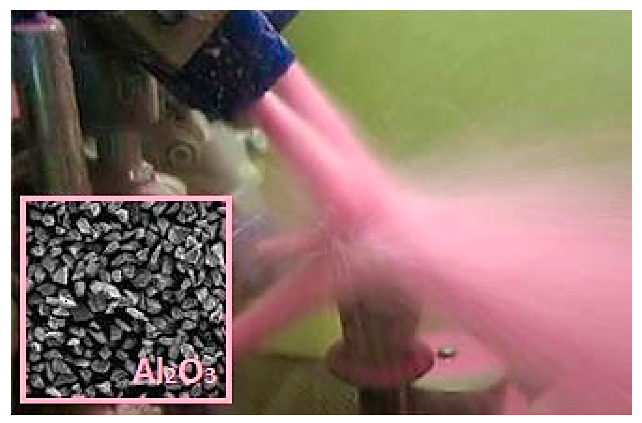
2.1. Abrasive Jet Machining
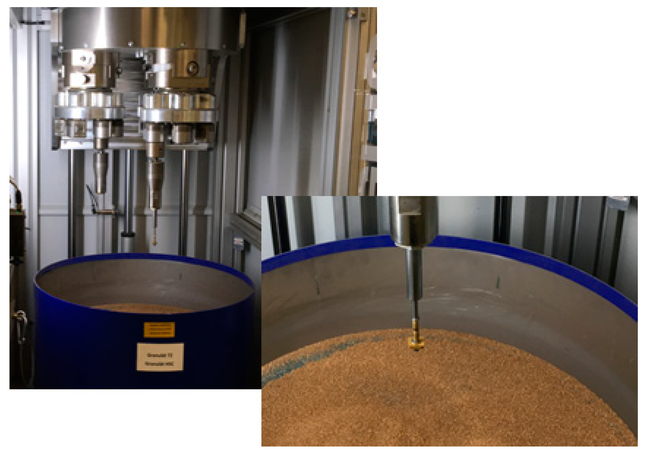
2.2. Drag Finishing
3. Measurement and Evaluation of Surface Quality of Cutting Inserts
4. Discussion of the Results
5. Conclusions
- Select cutting edge preparation and process parameters with regards to type and thickness of applied coating layer;
- Ensure higher surface quality before coatings due to copy the unevenness;
- Reduce the number of droplets and unevenness due to improvement surface roughness and sliding characteristics of the coatings;
- Ease or change the character of the effect of the residual stress in order to increase the fatigue life of applied coatings layer.
Author Contributions
Funding
Conflicts of Interest
References
- Denkena, B.; Lucas, A.; Bassett, E. Effect of the cutting edge geometry on tool wear ant its thermos-mechanical load. CIRP Ann. 2011, 6, 73–76. [Google Scholar] [CrossRef]
- Choudhury, I.A.; See, N.L.; Zukhairi, M. Machining with chamfered tools. J. Mater. Process. Technol. 2005, 170, 115–120. [Google Scholar] [CrossRef]
- Segebade, E.; Zanger, F.; Schulze, V. Influence of different asymmetrical cutting edge microgeometries on surface integrity. Procedia CIRP 2016, 45, 11–14. [Google Scholar] [CrossRef]
- Bouzakis, K.D.; Michailidis, N.; Skordaris, G.; Efstathiou, K.; Erkens, G. Optimization of the cutting edge roundness and its manufacturing procedures of cemented carbide inserts, to improve their milling performance after a PVD coating deposition. Surf. Coat. Technol. 2003, 133–134, 625–630. [Google Scholar] [CrossRef]
- Lo Casto, S.; Passannanti, G. On the influence of the radius between face and rake on the tool life of sintered carbides. CIRP Ann. 1985, 34, 83–85. [Google Scholar] [CrossRef]
- Rech, J.; Yen, Y.C.; Schaff, M.; Hamdi, H.; Altan, T.; Bouzakis, K.D. Influence of cutting edge radius on the wear resistance of PM-HSS milling inserts. Wear 2005, 259, 1168–1176. [Google Scholar] [CrossRef]
- Clausen, M.; Tracht, K.; Jivishov, V. Cutting force modelling and simulation. In Proceedings of the 36th CIRP International Seminar on Manufacturing Systems, Saarbrücken, Germany, 3–5 June 2003; pp. 425–432. [Google Scholar]
- Kim, K.; Lee, W.; Sin, H. A finite-element analysis of machining with the tool edge considered. J. Mater. Process. Technol. 1999, 86, 45–55. [Google Scholar]
- Özel, T.; Hsu, T.K.; Zeren, E. Effects of cutting edge geometry, workpiece hardness, feed rate and cutting speed on surface roughness and forces in finish turning of hardened AISI H13 steel. Int. J. Adv. Manuf. Technol. 2005, 25, 262–269. [Google Scholar] [CrossRef]
- Pawade, R.S.; Joshi, S.S.; Brahmankar, P.K. Effect of machining parameters and cutting edge geometry on surface integrity of high-speed turned Inconel 718. Int. J. Mach. Tools Manuf. 2008, 48, 15–28. [Google Scholar] [CrossRef]
- Rech, J. Cutting edge preparation and surface issues. In Proceedings of the International Conference Smart Solutions for Metal Cutting HSS Forum, Aachen, Germany, 2–3 February 2005; Volume 261, pp. 1–12. [Google Scholar]
- Zhao, F.X.; He, L.; Yuan, S.; Zheng, W.J. Influence of edge preparation parameters on the cutting edge in drag finishing. Key Eng. Mater. 2016, 693, 1067–1073. [Google Scholar] [CrossRef]
- Denkena, B.; Höhled, J.; Ventura, C.E.H. Customized cutting edge preparation by means of grinding. Precis. Eng. 2013, 37, 590–598. [Google Scholar] [CrossRef]
- Denkena, B.; Biermann, D. Cutting edge geometries. CIRP Ann. 2014, 63, 631–653. [Google Scholar] [CrossRef]
- Denkena, B.; Koehler, J.; Rehe, M. Influence of the honed cutting edge on tool wear and surface integrity in slot milling of 42CrMo4 steel. Procedia CIRP 2012, 1, 190–195. [Google Scholar] [CrossRef]
- Denkena, B.; Leon-Garcia, L.; Bassett, E. Five-axis brushing for cutting edge preparation. ATZ Prod. Worldw. 2009, 2, 18–21. [Google Scholar]
- Rodriguez, C.J.C. Cutting Edge Preparation of Precision Cutting Tools by Applying Microabrassive Jet Machining and Brushing, 1st ed.; Kassel University Press: Kassel, Germany, 2009; pp. 1–255. [Google Scholar]
- Hintermann, H.E. Adhesion, friction and wear of thin hard coantings. Wear 1984, 1–3, 381–397. [Google Scholar] [CrossRef]
- Prengel, H.G.; Pfouts, W.R.; Santhanam, A.T. State of the art in hard coatings for carbide cutting tools. Surf. Coat. Technol. 1998, 3, 183–190. [Google Scholar] [CrossRef]
- Dobrzanski, L.A.; Pakula, D.; Kriz, A.; Soković, M.; Kopac, J. Tribological properties of the PVD and CVD coatings deposited onto the nitride tool ceramics. J. Mater. Process. Technol. 2006, 1–3, 179–185. [Google Scholar] [CrossRef]
- Knotek, O.; Löffler, F.; Krämer, G. Substrate- and interface-related influences on the performance of arc-physical-vapour-deposition-coated cemented carbides in interrupted-cut machining. Surf. Coat. Technol. 1992, 54–55, 476–481. [Google Scholar] [CrossRef]
- Denkena, B.; Breidenstein, B. Cohesive Damage of PVD-Coated Cutting Tools—A Result of the Residual Stress Distribution. In Proceedings of the 9th International Conference THE-“A” Coatings in Manufacturing Engineering, Thessaloniki, Greece, 3–5 October 2011; pp. 89–97. [Google Scholar]
- Breidenstein, B.; Denkena, B. Significance of residual stress in PVD-coated carbide cutting tool. CIRP Ann. 2013, 6, 67–70. [Google Scholar] [CrossRef]
- Denkena, B.; Breindenstein, B. Residual stress distribution in PVD-coated carbide cutting tools—Origin of cohesive damage. Tribol. Ind. 2012, 3, 158–165. [Google Scholar]
- Denkena, B.; Breidenstein, B. Depth Resolved Residual Stress Measurements of Coated Carbide Cutting Inserts. In Proceedings of the 5th International Conference THE Coatings, Kallithea-Chalkidiki, Greece, 5–7 October 2005; pp. 285–294. [Google Scholar]
- Oettel, H.; Wiedemann, R. Residual stresses in PVD hard coatings. Surf. Coat. Technol. 1995, 1, 265–273. [Google Scholar] [CrossRef]
- Teixeira, V. Residual stress and cracking in thin PVD coatings. Vaccum 2002, 3–4, 393–399. [Google Scholar] [CrossRef]
- Bhatia, S.M.; Pandey, P.C.; Shan, H.S. Thermal cracking of carbide tools during intermittent cutting. Wear 1978, 2, 201–211. [Google Scholar] [CrossRef]
- Bhatia, S.M.; Pandey, P.C.; Shan, H.S. The thermal condition of the tool cutting edge in intermittent cutting. Wear 1980, 1, 21–30. [Google Scholar] [CrossRef]
- Bouzakis, K.D.; Michailidis, N.; Skordaris, G.; Bouzakis, E.; Biermann, D.; M’Saoubi, R. Cutting with coated tools: Coating technologies, characterization methods and performance optimization. CIRP Ann. Manuf. Technol. 2012, 61, 703–723. [Google Scholar] [CrossRef]
- Vogli, E.; Tillmann, W.; Selvadurai-Lassl, U.; Fischer, G.; Herper, J. Influence of Ti/TiAlN-multilayer designs on their residual stresses and mechanical properties. Appl. Surf. Sci. 2011, 11, 8550–8557. [Google Scholar] [CrossRef]
- Klocke, F.; Krieg, T. Coated tools for metal cutting-features and applications. CIRP Ann. Manuf. Technol. 1999, 48, 515–525. [Google Scholar] [CrossRef]
- Hronek, O.; Zetek, M. The influence of cutting edge radius on surface roughness when milling nickel alloy. In Proceedings of the 28th International DAAAM Symposium, Vienna, Austria, 8–11 November 2017; pp. 1037–1043. [Google Scholar]
- Biermann, D.; Asmuth, R.; Schumann, S.; Rieger, M.; Kuhlenkötter, B. Wet abrasive jet machining to prepare and design the cutting edge micro shape. In Proceedings of the 3rd CIRP Conference on Surface Integrity, Bochum, Germany, 8–10 June 2016; Volume 45, pp. 195–198. [Google Scholar]
- Hronek, O.; Zetek, M.; Baksa, T.; Adamek, P. Influence of holders speed on the cutting edge during drag finishing. Manuf. Technol. 2016, 16, 933–939. [Google Scholar]


| Kind of Medium | Blasting Distance | Belt Feed Rate | Blasting Angle | Air Pressure | Concentration | Process Time |
|---|---|---|---|---|---|---|
| pink Al2O3 - 240/280 mesh | 170 mm | 65 mm/min | ±30° | 2.5 bar | 80% water 20% medium | 6 min/100 pcs |
| Main Rotor | Small Rotor | Depth of Draft | Process Medium | Grain Size |
|---|---|---|---|---|
| 30 rpm | 50 rpm | 95 mm | walnut shell granulate impregnated with polishing paste | 0.8–1.3 mm |
| Type of Insert: SPKN 1203EDER-M | ||
|---|---|---|
| Coatings | PVD coatings - thickness 4 μm |  |
| TiN + multiplelayer structure TiAlN/TiN + TiN | ||
| (approx.: TiN—0.4 μm; TiAlN/TiN—3.4 μm; TiAlN—0.2 μm) | ||
| Substrate | sintered carbide |  |
| W = 87.1% | ||
| Cr = 0.7% | ||
| C = 3% | ||
| Co = 92 % | ||
| Parameter | Microgeometry Measurement – Magnification 50x | ||
|---|---|---|---|
| Vertical Resolution [µm] | Lateral Resolution [µm] | Cut-Off Filter λc [µm] | |
| 0.10 | 0.44 | 60.80 | |
| Specimen – A | Specimen – B | Specimen – C | |
| Sa [µm] | 0.21 | 0.11 | 0.14 |
| Sz [µm] | 4.83 | 3.02 | 4.19 |
| True color information |  |  |  |
| Pseudo color information |  | ||
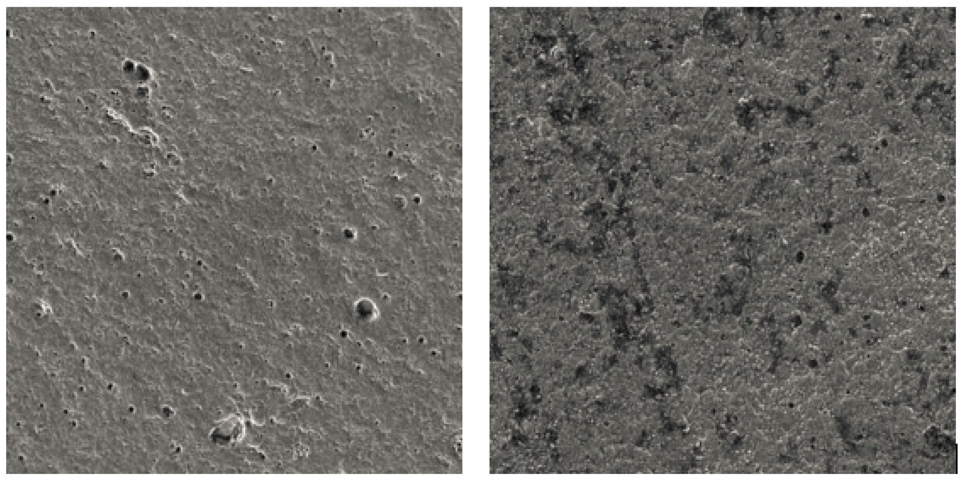
| Specimen A – Coating without Cutting Edge Preparation | |
| Magnification – 2000x | Magnification – 5000x |
 |  |
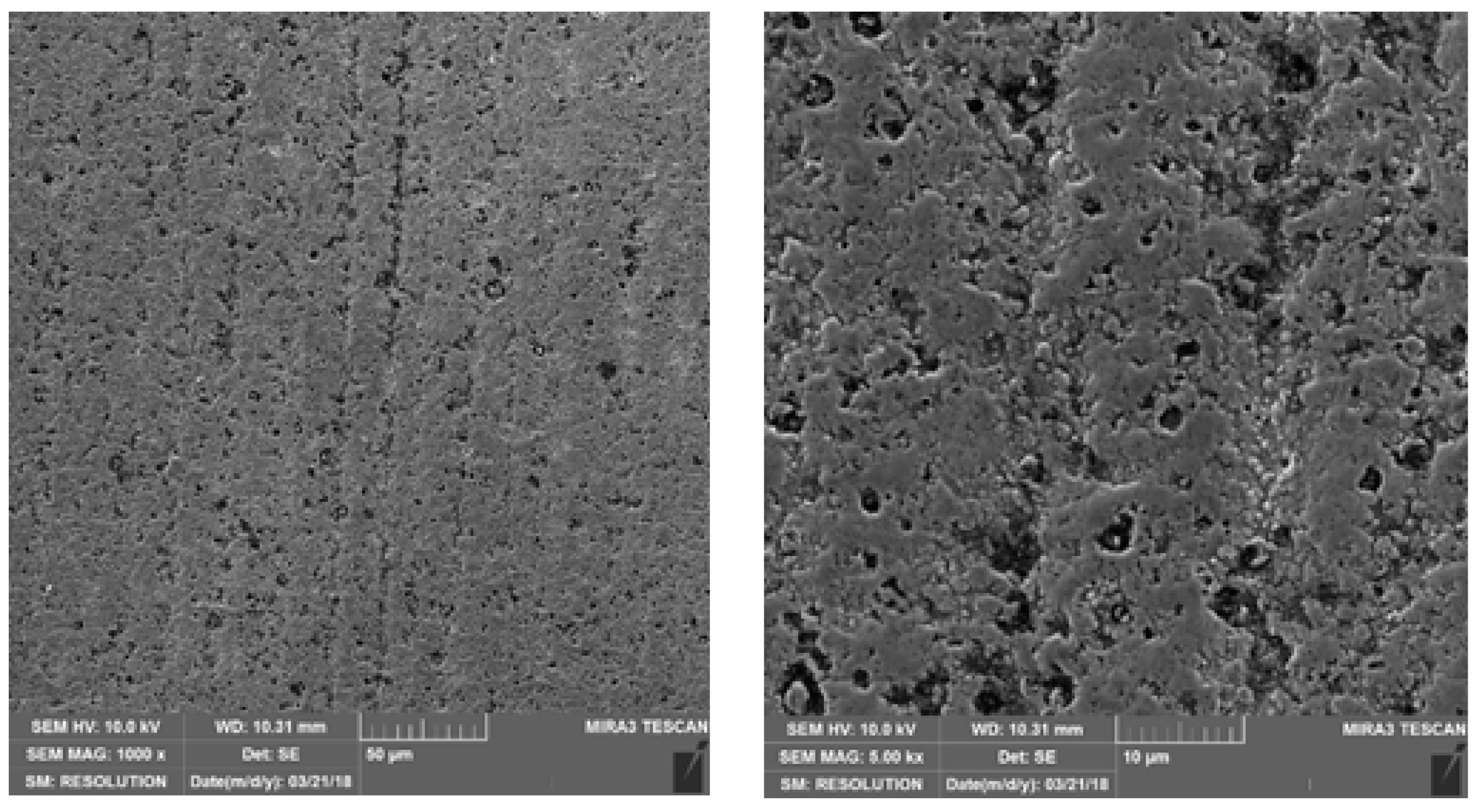
| Specimen B – Coating after Abrasive Jet Machining | |
| Magnification – 2000x | Magnification – 5000x |
 |  |
| Specimen C – Coating with Drag Finishing | |
| magnification – 2000x | magnification – 5000x |
 |  |
| Mill diameter | D = 100 mm |  |
| Entering angle | ĸr = 75° | |
| Cutting speed | vc = 400 m/min | |
| Revolution | rev. = 1256 rpm | |
| Cutting depth | ap = 2.5 mm | |
| Feed per tooth | fz = 0.2 mm | |
| Cutting width | ae = 50 mm | |
| Cutting length | L = 330 mm | |
| Cooling | YES |
| No. | Short Cycle - 2200 Shots per 1 Tooth | Long Cycle - 4400 Shots per 1 Tooth |
|---|---|---|
| A1 |  |  |
| B1 | ||
| C1 | ||
| A2 |  |  |
| B2 | ||
| C2 | ||
| A3 |  |  |
| B3 | ||
| C3 |
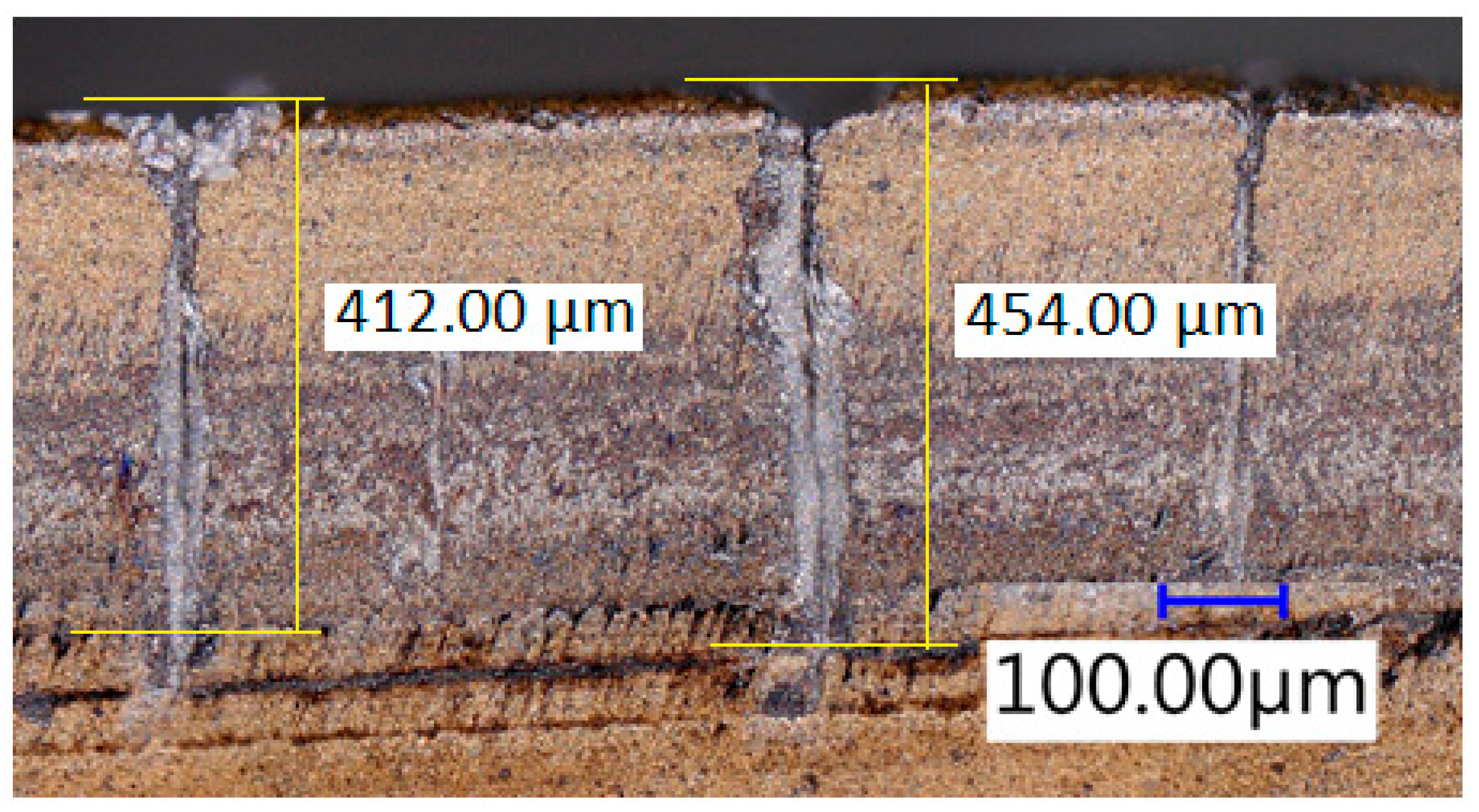
| Period | Short Cycle - 2200 Shots per 1 Tooth | Long Cycle - 4400 Shots per 1 Tooth | ||||
|---|---|---|---|---|---|---|
| Specimen | No. Cracks | Average Length [µm] | Chipping Yes/No | No. Cracks | Average Length [µm] | Chipping Yes/No |
| A1 | 4 | 487 | No | 5 | 496 | Yes |
| B1 | 2 | 412 | Yes | 3 | 566 | Yes |
| C1 | 2 | 295 | No | 3 | 370 | No |
| A2 | 2 | 390 | No | 2 | 409 | Yes |
| B2 | 2 | 308 | No | 2 | 512 | Yes |
| C2 | 0 | 0 | No | 2 | 247 | No |
| A3 | 3 | 398 | No | 2 | 355 | No |
| B3 | 1 | 401 | No | 3 | 470 | No |
| C3 | 2 | 607 | No | 3 | 400 | No |
© 2019 by the authors. Licensee MDPI, Basel, Switzerland. This article is an open access article distributed under the terms and conditions of the Creative Commons Attribution (CC BY) license (http://creativecommons.org/licenses/by/4.0/).
Share and Cite
Zlamal, T.; Mrkvica, I.; Szotkowski, T.; Malotova, S. The Influence of Surface Treatment of PVD Coating on Its Quality and Wear Resistant. Coatings 2019, 9, 439. https://doi.org/10.3390/coatings9070439
Zlamal T, Mrkvica I, Szotkowski T, Malotova S. The Influence of Surface Treatment of PVD Coating on Its Quality and Wear Resistant. Coatings. 2019; 9(7):439. https://doi.org/10.3390/coatings9070439
Chicago/Turabian StyleZlamal, Tomas, Ivan Mrkvica, Tomas Szotkowski, and Sarka Malotova. 2019. "The Influence of Surface Treatment of PVD Coating on Its Quality and Wear Resistant" Coatings 9, no. 7: 439. https://doi.org/10.3390/coatings9070439