Article

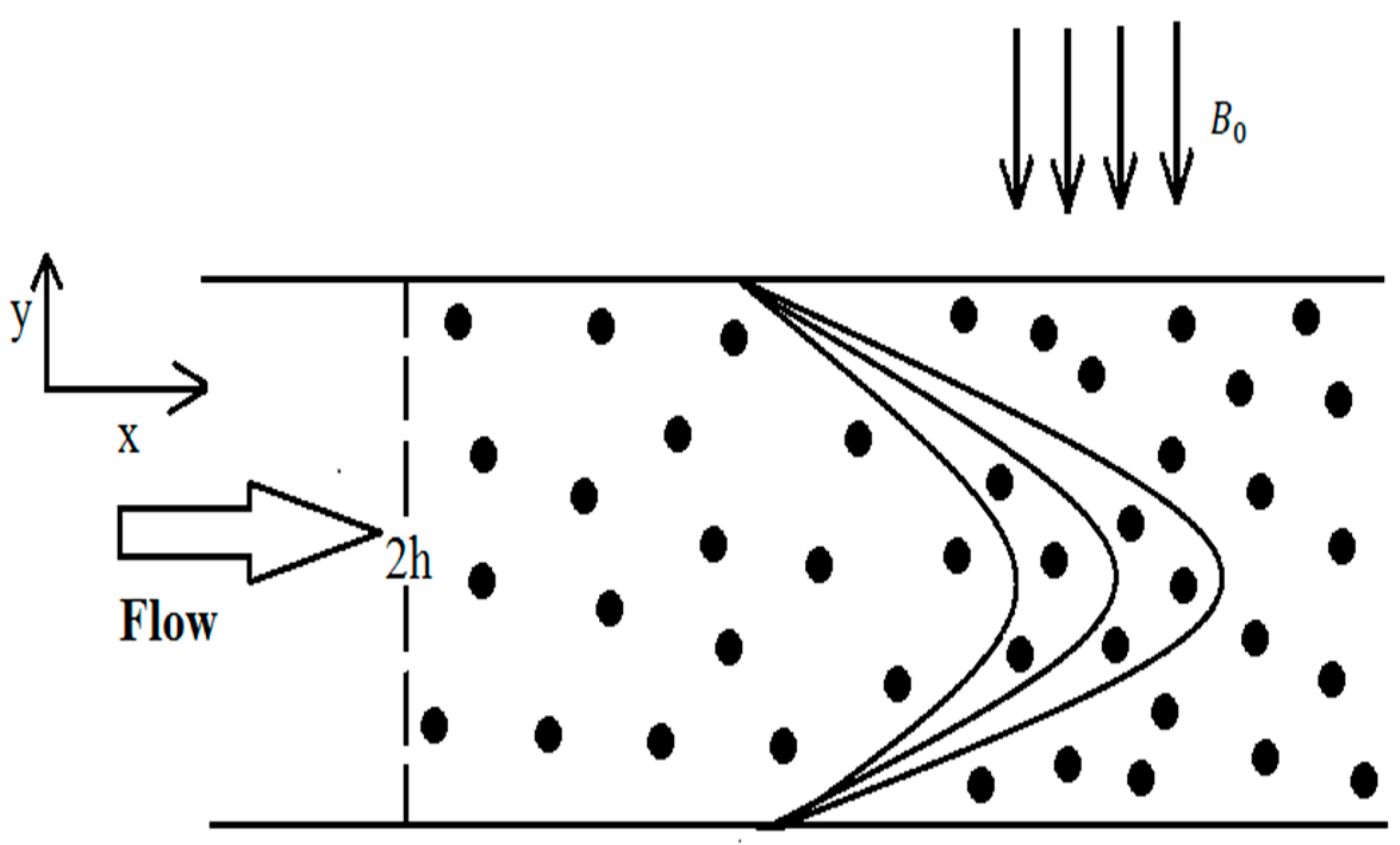
Thermally Charged MHD Bi-Phase Flow Coatings with Non-Newtonian Nanofluid and Hafnium Particles along Slippery Walls

1
Center for Modeling & Computer Simulation, Research Institute, King Fahd University of Petroleum & Minerals, Dhahran 31261, Saudi Arabia
2
Department of Mathematics & Statistics, Faculty of Basic and Applied Sciences (FBAS), International Islamic University (IIUI), Islamabad 44000, Pakistan
3
Department of Mathematics, Faculty of Arts and Basic Sciences (FABS), Balochistan University of Information Technology, Engineering, and Management Sciences (BUITEMS), Quetta 87300, Pakistan
4
Department of Mathematics, University of Education Lahore, Faisalabad Campus, Faisalabad 38000, Pakistan
*
Author to whom correspondence should be addressed.
Coatings 2019, 9(5), 300; https://doi.org/10.3390/coatings9050300
Submission received: 19 March 2019 / Revised: 13 April 2019 / Accepted: 29 April 2019 / Published: 2 May 2019
(This article belongs to the Special Issue Recent Trends in Coatings and Thin Film–Modeling and Application)

Abstract

:
The present study is about the pressure-driven heated bi-phase flow in two slippery walls. The non-Newtonian couple stress fluid is suspended with spherically homogenous metallic particles. The magnetic susceptibility of Hafnium allures is taken into account. The rough surface of the wall is tackled by lubrication effects. The nonlinear coupled partial differential equations along with the associated boundary conditions are first reduced into a set of ordinary differential equations by using appropriate transformations and then numerical results were obtained by engaging the blend of Runge–Kutta and shooting techniques. The sway of physical quantities are examined graphically. An excellent agreement within graphical illustration and numerical results is achieved.

1. Introduction

The most common fundamental type of flow through a channel is known as “Poiseuille flow.” The Poiseuille flow has gained notable attention of various researchers due to its significant industrial applications. As an example, Siddiqui et al. [1] studied the plane Poiseuille flow with heat transfer. Alamri et al. [2] examined the plane Poiseuille flow with simultaneous effects of heat, magnetohydrodynamics (MHD) and second-order slip. They reported that the Stefan blowing prominently influenced on velocity and temperature distributions. Babic [3] has numerically investigated unsteady granular flows, namely transient Couette flow and cyclic Couette flow. In the first case velocity of the wall varies from one constant to another while in the second case the velocity is a harmonic function of time.
Moreover, non-Newtonian fluids have tremendous applications in the textile industry. Among the different models of non-Newtonian fluids, couple stress fluid has only lubricant viscosity. Consequently, in the absence of microstructure, couple stress in fluid arises which creates rotation without translation. Devakar et al. [4] investigated the couple stress fluid for three different cases. Ilani et al. [5] presented the unsteady nature of couple stress fluid between two parallel plates. Srinivasacharya et al. [6] discussed the laminar flow of couple stress fluid by means of quasi-linearization technique. Murthy and Nagaraju [7] conducted a study of couple stresses on the surface of a cylinder. The rotation of the container generates the flow employing super adherence condition. All reported studies on couple stress eventually concluded that velocity always slows down in the fluid due to couple stresses by all means. Significant contributions on couple stress fluid can be seen in [8,9,10].
Furthermore, it is a well-known fact that most of the chemical and mechanical processes are of multiphase types. Consequently, several investigations have been performed up until now. In near past, different physical aspects of bi-phase flows were investigated by numerous researchers, such as Wu et al. [11], who discussed granular flow between opposite inclined plates for second-grade fluid containing spherical particles. Bognar et al. [12] offered flow analysis of non-Newtonian fluid on an oblique plane with material properties. Latz and Schmidt [13] presented numerical solutions for fast-moving and very slow-moving granular flows. Latz and Schmidt [14] provided numerical solutions for fast-moving and very slow-moving granular flows. The constitutive relations at small and intermediate densities were equivalent to those derived from the kinetic theory of granular flow which nevertheless recovers many aspects of dense granular flow. Two-phase fluids are inspected by Armanini [15]. The article provides full detail as to how granular fluid mechanics work. Interaction of solid–fluid for particulate flow with heat transfer is analyzed by Dan et al. [15]. Distributed Lagrange multipliers are used to obtain the expressions for velocity and temperature fields. The Boussinesq approximation is used for temperature and flow fields. The positioning of the particle is tracked by using the discrete element method.
In addition, the performance of lubricated coatings with magnetic, nanoparticles, heat transfer, and slip is very much ubiquitous in daily life. For instance, dish washing, replacement of lubricated cardiac valves, and industrial dye, as well as blood pressure control of a patient, are some common examples of slip and magnetization combination. Wang et al. [16] reported the effects of CeO2 nanoparticles on laser cladding of Ti-based ceramic coatings. Wang et al. [17] studied nanostructure with heating treatment on thin carbon films. Ellahi et al. [18] conducted a comparative study on shiny film coating on multi-fluid flows suspended with nano-sized particles. Khan et al. [19] have used double-layer optical fiber using Phan-Thien-Tanner fluid as a coating material. Lu et al. [20] inspected nonlinear thermal radiation and entropy optimization coatings with hybrid nanoliquid flow. Riaz et al. [21] proposed a model on mass transport peristaltic flow coated with Synovial fluid. Khan [22] has analyzed the effects of slip on MHD flow of a nanofluid in a vertical channel. Bhatti et al. [23] have investigated nanofluid influenced by externally applied magnetic fields. A new slip model is proposed by Zhu and Ye [24]. They used modeling approaches for submicrometer gas-phase heat conduction over a broad pressure range. Zhang et al. [25] rectified the classical second-order boundary condition for the fundamental flows. A list of core investigations on coatings [26,27], MHD [28,29], and nanoparticles [30,31,32,33,34,35,36,37] related to proposed is given for readers to get detail understating.
Unlike all the cited literature, this article addresses a biphasic flow that has yet not been reported. Much has been done with couple stress fluid; suspension of nanoparticles, slip, and magnetic fields, but the current innovative idea, which reflects the mechanism of industrial and geophysical multiphase flows is missed. Theory of couple stress fluid which is based upon the polarity of fluid entices to incorporate metallic particles that display high magnetic susceptibility. Therefore, no choice is left other than the suspension of Hafnium particles that fit the best. An additional contribution of lubrication and heating wall distinguish the present work by changing the morpho-hydrodynamics of bi-phase flow, which is, so far, a new and different prospect in the relevant field.

2. Mathematical Analysis

The particulate couple stress fluid containing Hafnium particles of spherical shape between two flat plates apart from each other at distance h is considered. Flow is generated by the constant pressure gradient, as shown in Figure 1.

2.1. Governing Equations

The governing equations, such as continuity, momentum, and energy describing the particulate flow of couple stress, are given as:
• Conservation of mass
¯ V = 0
• Conservation of momentum
ρ d V d t = T + C S ( 1 C ) (   V p V f ) + ρ f ( 1 C )
where T denotes the Cauchy stress tensor and is defined by
T = p I + s
where I is a unit tensor and s is an extra stress tensor. This can be obtained by the product of Rivlin–Ericksen tensor and coefficient of dynamic viscosity as follows:
s = μ s   A 1
A 1 = L + L t
• Conservation of energy
ρ f ( C p ) d Θ d t = k   2 V + T L
The steady and laminar velocities flows in each phase is given by:
V f = [ u f ( x , y )     0     0 ]
V p = [ u p ( x , y )     0     0 ]
The flow is under the simultaneous influences of transversely applied magnetic fields. Moreover, the plates transmit the heat into the system being thermally charged by an external source; consequently, temperature factor can be written as:
Θ = [ Θ ( y )     0     0 ]
In view of Equations (7)–(9), the above governing equations (Equations (1)–(6)) take the following components forms:
0 = p x + μ s ( 2 u f y 2 ) η 1 ( 4 u f y 4 ) + C S ( 1 C ) (   u p u f ) σ B 0 2 ( 1 C ) u f
u p = u f 1 S ( p x )
0 = 2 Θ y 2 + μ s k ( u f y ) 2 η 1 k ( u f y ) ( 3 u f y 3 )

2.2. Boundary Conditions

The set of boundary conditions that describe the interaction of lubricated walls with the bi-phase flow are:
• Boundary conditions at lower wall
u f ( y ) = β { u f y η 1 μ s ( 3 u f y 3 ) } ,   w h e n   y = h
  u f ( y ) = 0 ,   w h e n   y = h
Θ ( y ) = Θ 0 ,   w h e n   y = h
• Boundary conditions at upper wall
u f ( y ) = β { u f y η 1 μ s ( 3 u f y 3 ) } ,   w h e n   y = h
u f ( y ) = 0 ,   w h e n   y = h
Θ ( y ) = Θ l ,   w h e n   y = h
By using the dimensionless quantities:
u f = U u f ;     u p = U u p ;       y = h y   ;     x = h x ;     p =   μ s U h   p ;     B r = U 2 μ s k ( Θ l Θ 0 ) ; γ 2 =   h 2 μ s η 1 ;     M 2 = σ B 0 2   h 2 μ s ;     β 1 = β h ;       m = μ s h 2 S   ;       Θ ( Θ l Θ 0 ) = Θ Θ 0
Equations (10)–(12), after dropping the bars, can be obtained as:
1 γ 2 4 u f y 4 2 u f y 2 C m ( 1 C ) (   u p u f ) +   M 2 ( 1 C ) u f + p x = 0
2 Θ y 2 = B r γ 2 ( u f y ) ( 3 u f y 3 ) B r ( u f y   ) 2
where
u p = u f m ( p x )
As the original source of magnetized and heated bi-phase is on slippery walls and constant pressure gradient. Therefore, by taking of dp/dx = P, Equations (20) and (21) can be obtained as:
d 4 u f d y 4 γ 2 d 2 u f d y 2 +   γ 2 M 2 ( 1 C ) u f + γ 2 ( 1 C ) P = 0
d 2 Θ d y 2 + B r ( d u f d y   ) 2 B r γ 2 ( d u f d y ) ( d 3 u f d y 3 ) = 0
Similarly, in view of Equation (19), the corresponding boundary conditions given in Equations (13)–(18) in the dimensionless form are:
u f ( y ) = β 1 { d u f d y 1 γ 2 ( d 3 u f d y 3 ) } ,   w h e n   y = 1
u f ( y ) = 0 ,   w h e n   y = 1
Θ ( y ) = 0 ,   w h e n   y = 1
u f ( y ) = β 1 { d u f d y 1 γ 2 ( d 3 u f d y 3 ) } ,   w h e n   y = 1
u f ( y ) = 0 ,   w h e n   y = 1
Θ ( y ) = 1 ,   w h e n   y = 1

3. Numerical Results and Discussion

3.1. Procedure

This section is devoted to obtaining the numerical solutions of resulting Equations (23) and (24) by means of the Runge–Kutta method with a shooting technique [38] using MATLAB software. This technique is preferred for two following reasons; firstly, the thermal energy equation is nonlinearly coupled and, secondly, due to missing of condition. For missing condition, first of all, we are supposed to convert the given system of differential equations into first-order initial value problems in order to carry out systematic guessing of missing initial conditions which will continue until the desired accuracy and convergence are not achieved. The following equations explain in detail the numerical process, which is the prerequisite for the adopted numerical technique.
u f = g 1
in which of u f is the velocity of the fluid phase. As it is an iterative scheme, in which each step has a possible error that can be successively reduced by changing higher order derivatives of u f in terms of first-order ordinary differential equations as follows:
d u f d y = g 1 = g 2
d 2 u f d y 2 = g 2 = g 3
d 3 u f d y 3 = g 3 = g 4
where prime denoted the differentiation with respect to y . In view of Equations (31)–(34) the transformed form of Equation (23) is obtained as:
g 4 = γ 2 g 3 ( γ 2 M 2 1 C ) g 1 ( γ 2 1 C )   P
Similar to the preceding pattern, one finds no absurdness to convert thermal differential Equation (24) into first-order system by making the following suppositions:
Θ = g 5
d Θ d y = g 5   = g 6
By using Equations (36) and (37) in Equation (24), we have:
g 6   = B r m   ( g 2 ) ( g 4 ) B r   ( g 2 ) 2
In view of Equations (35) and (38), the associated boundary conditions given in Equations (25) to (30) at the lower and upper plate can be obtained as:
( i )   g 1 = β 1 ( g 2 g 4 γ 2 ) ( i i )   g 2 = c 1 ( i i i )   g 3 = 0 ( i v )   g 4 = c 2 ( v )     g 5 = 0 ( v i )     g 6 = c 3 } w h e n   y = 1
In the same way given and missing conditions at the upper wall are:
( i )     g 1 = β 1 ( g 2 g 4 γ 2 ) ( i i )     g 2 = c 4 ( i i i )     g 3 = 0 ( i v )     g 4 = c 5 ( v )     g 5 = 1 ( v i )     g 6 = c 6 }   w h e n   y = 1
where c 1 c 2 c 3 c 4 c 5   and   c 6 are the missing conditions which can be easily determined during the routine calculation.

3.2. Validation

The numerical results for both phases are presented in Table 1, Table 2 and Table 3. Table 1 offers the variation of velocity for both phases against the slip parameter. Table 2 shows the simultaneous variations in the velocities for single- and two-phase flows at different points. Table 3 displays the thermal variation at different points within the given domain when M = 0.5, γ = 2.0, and Br = 2.0. It is found that the results extracted numerically are compatible with the physical expectations and satisfy all the subjected conditions as shown graphically. This provides a useful check that the presented solutions are correct.

3.3. Discussion

In this section, a concise study of pertinent parameters is graphically presented in Figure 2, Figure 3, Figure 4, Figure 5, Figure 6, Figure 7, Figure 8, Figure 9 and Figure 10. Figure 2 and Figure 3 are plotted to examine the influence of the magnetic parameter on the motion of couple stress fluid and metallic Hafnium particles. In both graphs, a clear decline in velocities for higher values of the magnetic parameter is observed. Nevertheless, the theory of Hannes Alfven explains the same phenomenon involving the interaction of magnetic fields being induced into an electrically conducting fluid system. This phenomenon produces Alfven waves which result in clear retardation of fluid’s speed. However, in Figure 4 and Figure 5, the density of the Hafnium particles brings out a different result as compared to magnetic fields. The major push of pressure on the fluid on slippery walls, the hydro motion in both phases is supported by the addition of extra metallic particles. Consequently, velocity increases by increasing the number of particles. Such factors can be regarded as to attenuate the interaction of fluid particle or interparticle collision allowing the particles to move with least resistance. The most significant parameter which constitutes the existence of the present fluid flow is couple stress parameter   γ . It is observed that the fluid particle additives, contribute to expediting the movement. This may cause obscurity and vagueness in the mind of a reader, but Equations (23), (28), and (31) provide enough clues about the inverse influence of couple stress parameter on the flow that attenuates the force of friction/drag arising from the effect base fluid’s accumulation. This constitutes a size-dependent effect in the base fluid, in addition to minimizing the rotational field of the fluid particles. Hence, rapid fluid flow is observed in both Figure 6 and Figure 7. However, the contribution of slippery walls is not negligible, as they assist the metallic particles to frisk freely in the liquid. The role of the slip parameter that supports the velocity of both phases is spotted in Figure 8 and Figure 9. Generally, it is believed that slippery walls only snag the flow because of their behavior as a retarding force. Against all such expectations, in the present study, slip effects bring about unprecedented change by increasing the velocity of the fluid, as shown in Figure 8. This change is due to the inverse influence of γ, given in Equations (28) and (31) which rebuffs all such perception that slip parameter merely hampers the flow. The change in temperature through Brinkman number Br is sketched in Figure 10. It is revealed that the higher values of Brinkman heat up the fluid temperature.

4. Conclusions

In this study, the heated couple stress bi-phase fluid with spherical particles of metal Hafnium is investigated. The flow bounded by two parallel plates is caused by solely the influence of pressure gradient in an axial direction. A uniform and constant magnetic field of strength B0 snags the flow, transversely acting across the channel. Extra effects of lubrication are applied on both walls to minimize the surface roughness and to attain a smooth flow. The significant outcomes of the analysis are:
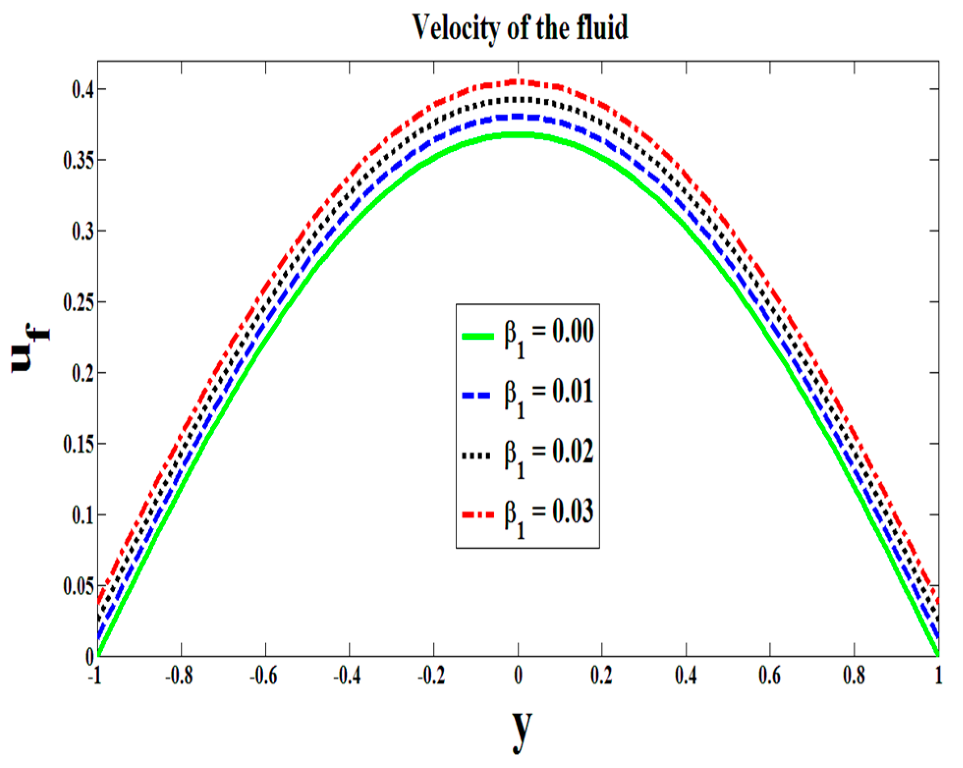
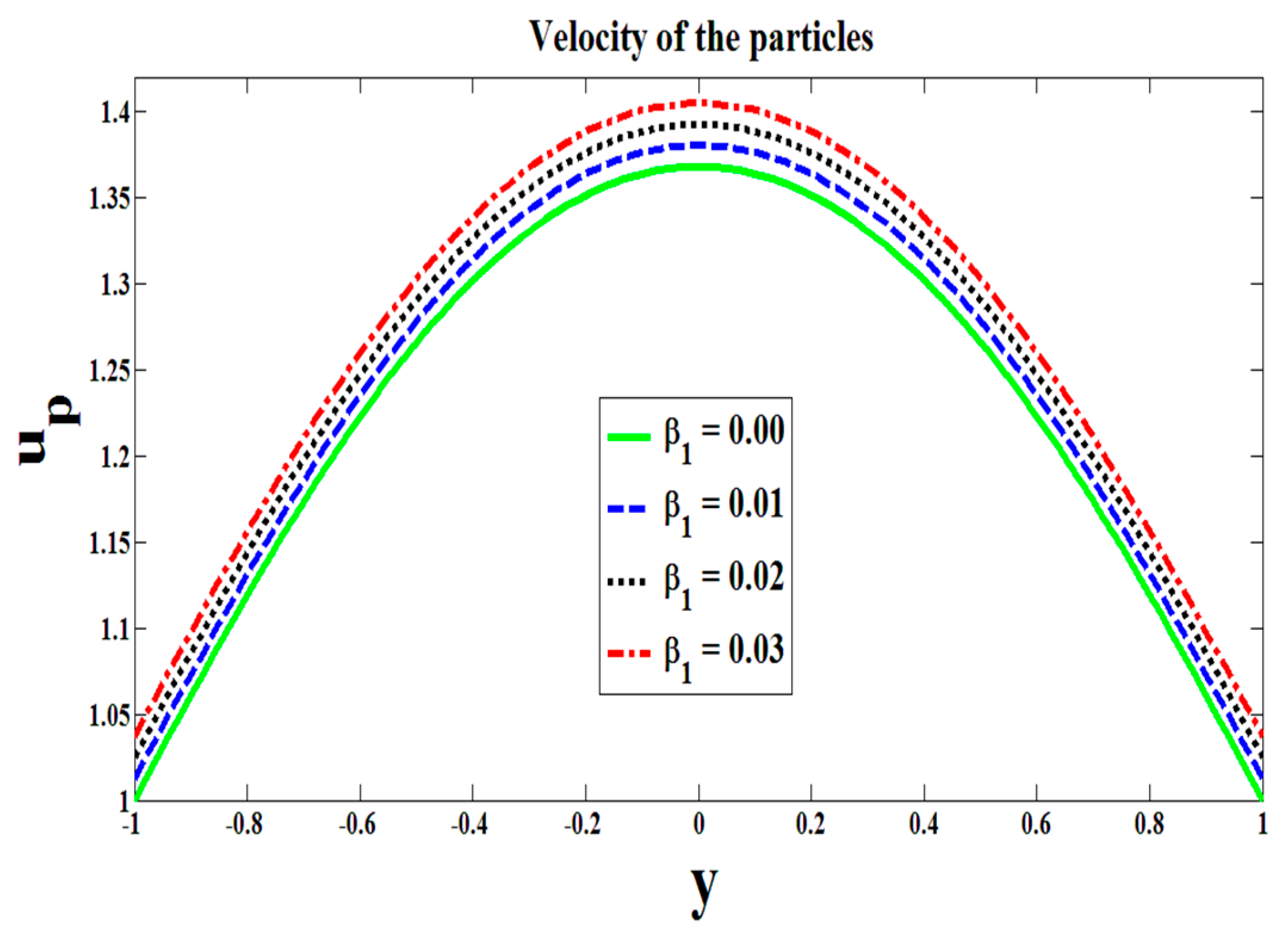
  • The velocity of each phase increases due to an increase in the slip parameter.
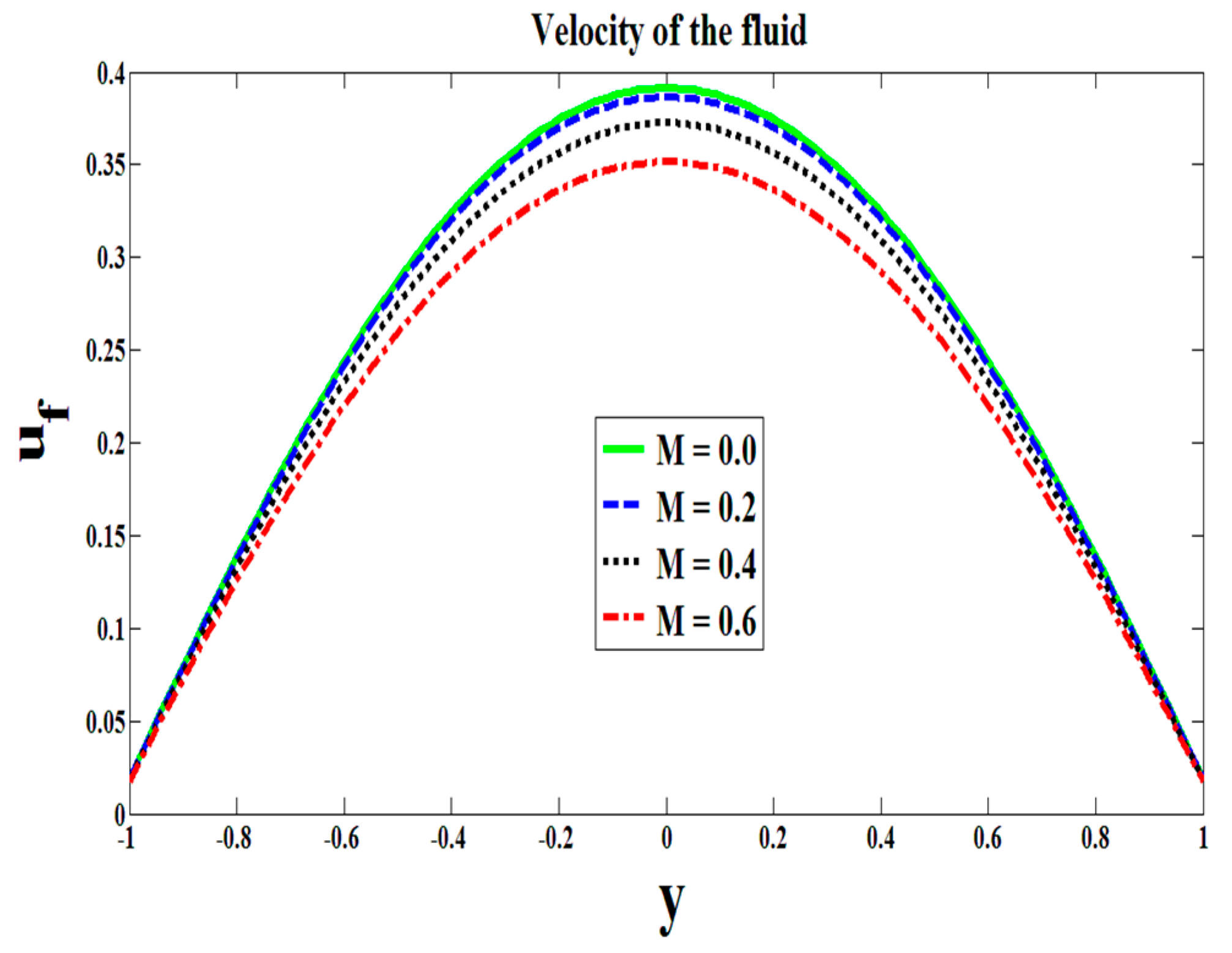
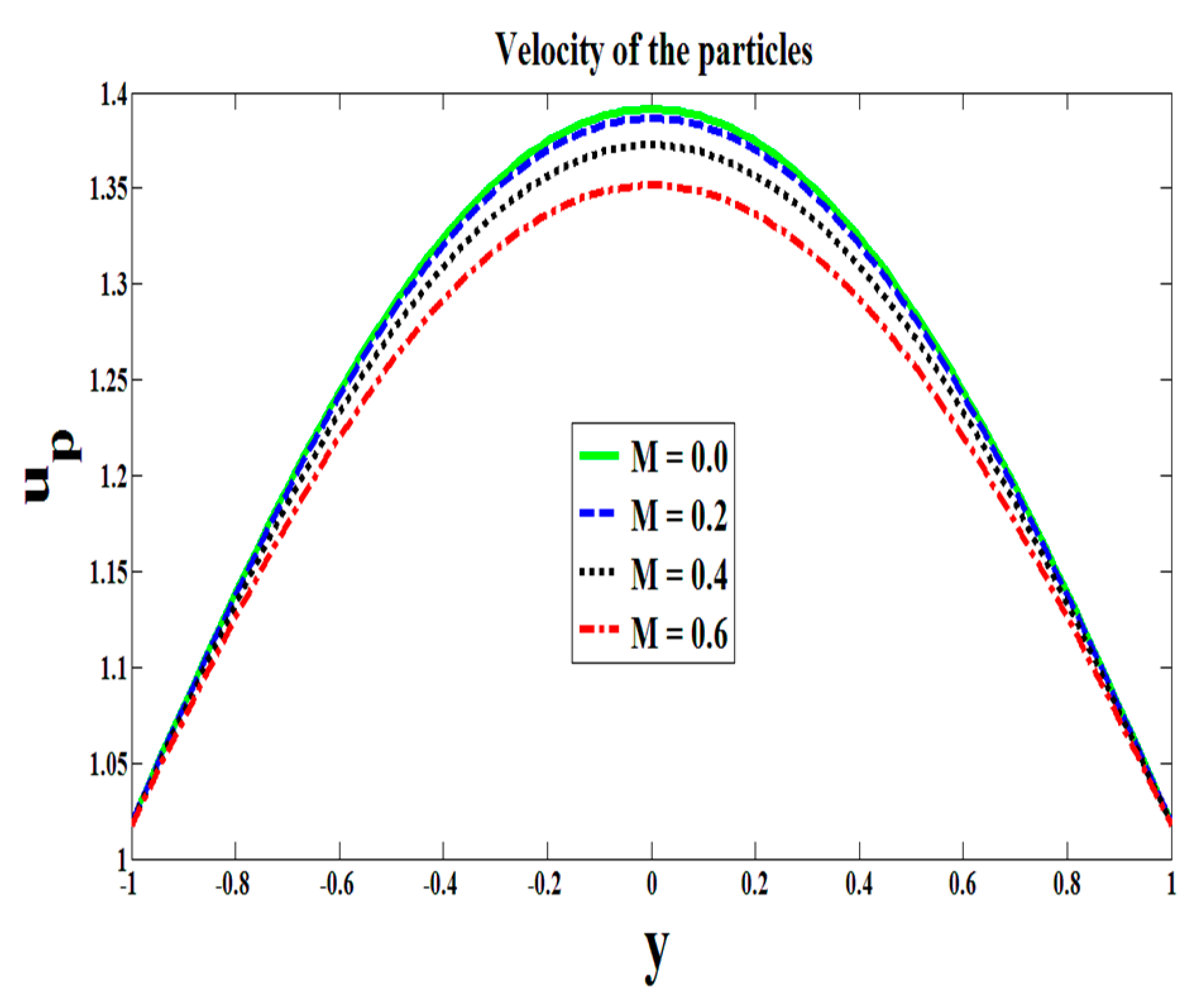
  • The magnetic field does not support the flow and ends up causing a force of resistance.
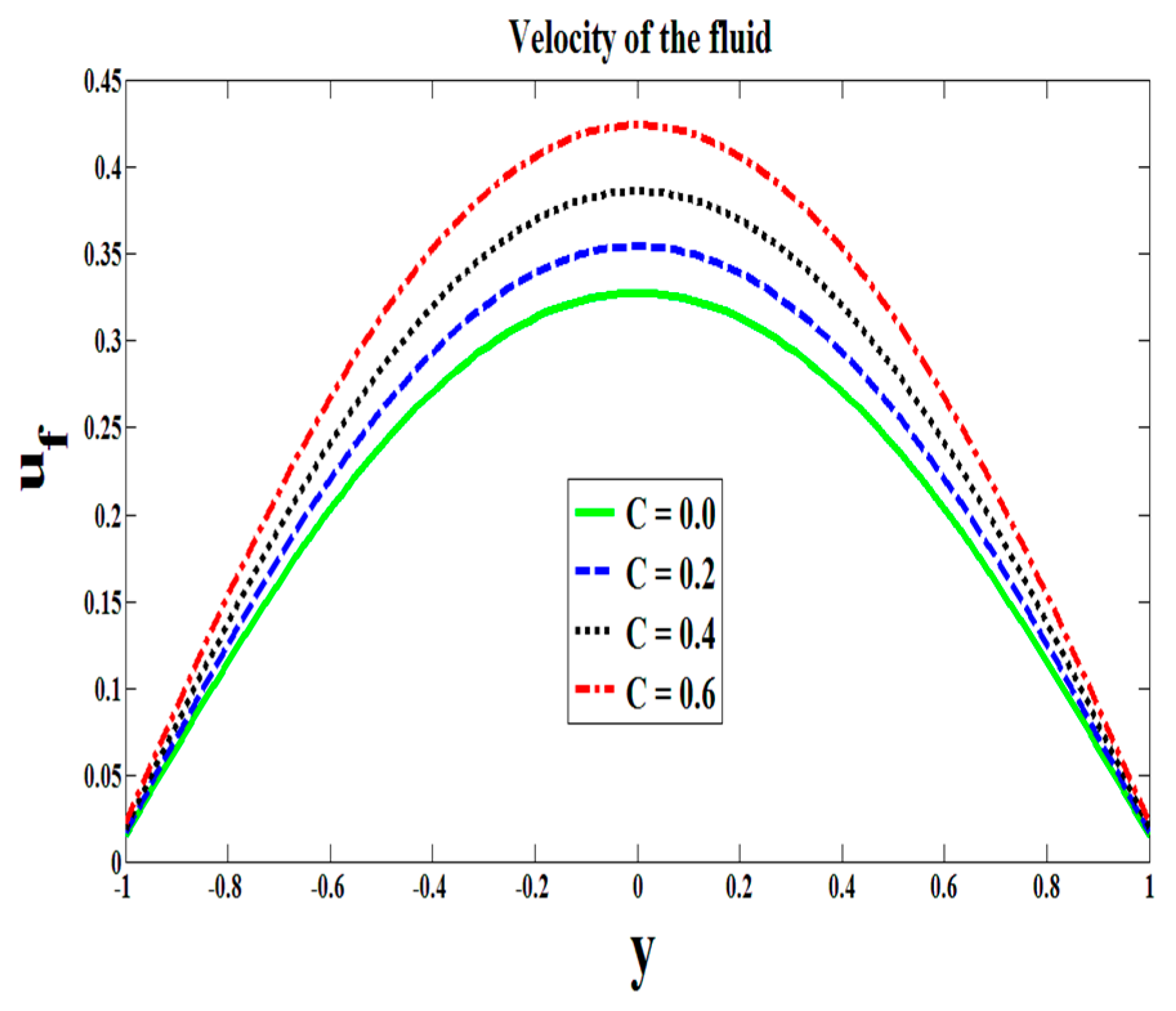
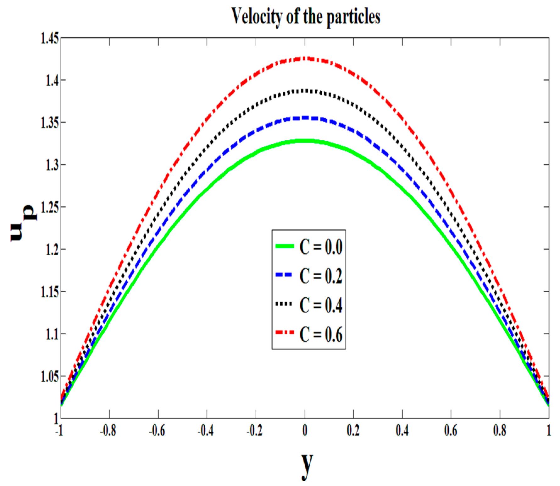
  • The molecules additives of base fluid reduce the force of friction and hence velocities of both phases are galvanized.
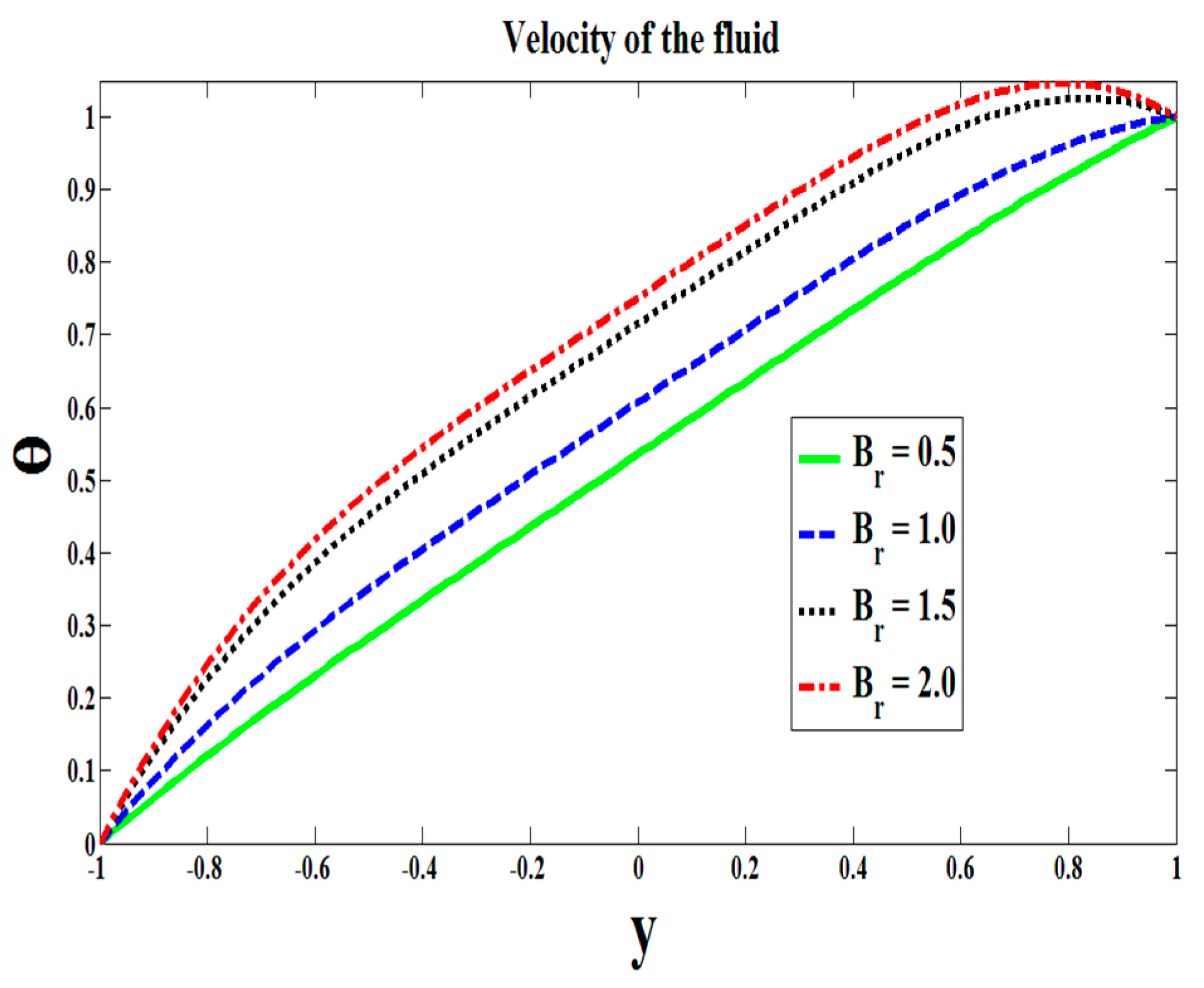
  • The temperature of the flow escalates for higher values of Brinkman number.

Author Contributions

Conceptualization, R.E.; Writing—Review and Editing, A.Z.; Methodology, F.H.; Investigation, T.A.

Funding

This research received no external funding.

Acknowledgments

Rahmat Ellahi thanks the Director Office of Research Chair Professors, King Fahd University of Petroleum and Minerals, Dhahran, Saudi Arabia, to honor him with the Chair Professor at KFUPM. Farooq Hussain also acknowledges the Higher Education Commission Pakistan to provide him the indigenous scholarship for the pursuance of his Ph.D. studies.

Conflicts of Interest

The authors declare no conflict of interest.

Nomenclature

u f velocity of base fluid
h distance between plates
p pressure
t time
M Hartmann number
U reference velocity
B 0 magnetic field
C number density of the particles
u p velocity of particle
f body force
f body force
k thermal conductivity
C p specific heat
m dimensionless constant
B r brinkman number
S drag force coefficient
Greek Symbols
γcouple stress parameter
ρfdensity of base fluid
η1constant associated to couple stress fluid
Θ0temperature of lower wall
μsviscosity
δ electric conductivity
ρdensity of the suspension
βslip length
Θdimensional temperature
Θltemperature of upper wall
β1slip parameter

References

  1. Siddiqui, A.M.; Zeb, A.; Ghori, Q.K.; Benharbit, A.M. Homotopy perturbation method for heat transfer flow of a thirdgrade fluid between parallel plates. Chaos Solition Fract. 2008, 36, 182–192. [Google Scholar] [CrossRef]
  2. Alamri, S.Z.; Ellahi, R.; Shehzad, N.; Zeeshan, A. Convective radiative plane Poiseuille flow of nanofluid through porous medium with slip: An application of Stefan blowing. J. Mol. Liq. 2019, 273, 292–304. [Google Scholar] [CrossRef]
  3. Babic, M. Unsteady Couette granular flows. Phys. Fluids 1997, 9, 2486–2505. [Google Scholar] [CrossRef]
  4. Devakar, M.; Sreenivasu, D.; Shankar, B. Analytical solutions of couple stress fluid Flows with slip boundary conditions. Alexandria Eng. J. 2014, 53, 723–730. [Google Scholar]
  5. Ilani, S.S.; Ashmawy, E.A. A time dependent slip flow of a couple stress fluid between two parallel plates through state space. J. Taibah Univ. Sci. 2018, 12, 1658–3655. [Google Scholar] [CrossRef]
  6. Srinivasacharya, D.; Srinivasacharyulu, N.; Odelu, O. Flow and heat transfer of couple stress fluid in a porous channel with expanding and contracting walls. Int. Commun. Heat Mass Transf. 2009, 36, 180–185. [Google Scholar] [CrossRef]
  7. Murthy, J.V.; Nagaraju, G. Flow of a couple stress fluid generated by a circular cylinder subjected to longitudinal and torsional oscillations. Contemp. Eng. Sci. 2009, 2, 451–461. [Google Scholar]
  8. Hussain, F.; Ellahi, R.; Zeeshan, A.; Vafai, K. Modelling study on heated couple stress fluid peristaltically conveying gold nanoparticles through coaxial tubes: A remedy for gland tumors and arthritis. J. Mol. Liq. 2018, 268, 149–155. [Google Scholar] [CrossRef]
  9. Ellahi, R.; Zeeshan, A.; Hussain, F.; Asadollahi, A. Peristaltic blood flow of couple stress fluid suspended with nanoparticles under the influence of chemical reaction and activation energy. Symmetry 2019, 11, 11–276. [Google Scholar] [CrossRef]
  10. Shit, G.C.; Ranjit, N.K. Role of slip velocity on peristaltic transport of couple stress fluid through an asymmetric non-uniform channel: Application to digestive system. J. Mol. Liq. 2016, 221, 305–315. [Google Scholar] [CrossRef]
  11. Wu, W.-T.; Aubry, N.; Antaki, J.F.; Massoudi, M. Normal stress effects in the gravity driven flow of granular materials. Int. J. Nonlin. Mech. 2017, 92, 84–91. [Google Scholar] [CrossRef]
  12. Bognár, G.; Gombkötő, E.; Hriczó, K. Non-Newtonian fluid flow down an inclined plane. Available online: https://pdfs.semanticscholar.org/356f/347b565104a37ddb2440442a08d98ba5a057.pdf (accessed on 2 May 2019).
  13. Latz, A.; Schmidt, S. Hydrodynamic modeling of dilute and dense granular flow. Granul Matter 2010, 12, 387–397. [Google Scholar] [CrossRef]
  14. Armanini, A. Granular flows driven by gravity. J. Hydraul. Res. 2013, 51, 111–120. [Google Scholar] [CrossRef]
  15. Dan, C.; Wachs, A. Direct Numerical Simulation of particulate flow with heat transfer. Int. J. Heat Fluid Flow 2010, 31, 1050–1057. [Google Scholar] [CrossRef]
  16. Wang, H.; Chen, T.; Cong, W.; Liu, D. Laser cladding of Ti-based ceramic coatings on Ti6Al4V alloy: Effects of CeO2 nanoparticles additive on wear performance. Coatings 2019, 9, 109. [Google Scholar] [CrossRef]
  17. Wang, Z.; Gao, K.; Zhang, B.; Gong, Z.; Wei, X.; Zhang, J. Verification study of nanostructure evolution with heating treatment between thin and thick fullerene-like hydrogen carbon films. Coatings 2019, 9, 82. [Google Scholar] [CrossRef]
  18. Ellahi, R.; Zeeshan, A.; Hussain, F.; Abbas, T. Study of shiny film coating on multi-fluid flows of a rotating disk suspended with nano-sized silver and gold particles: A comparative analysis. Coatings 2018, 8, 422. [Google Scholar] [CrossRef]
  19. Khan, Z.; Rasheed, H.U.; Alharbi, S.O.; Khan, I.; Abbas, T.; Chin, D.L.C. Manufacturing of double layer optical fiber coating using phan-thien-tanner fluid as coating material. Coatings 2019, 9, 147. [Google Scholar] [CrossRef]
  20. Lu, D.; Ramzan, M.; Ahmad, S.; Shafee, A.; Suleman, M. Impact of nonlinear thermal radiation and entropy optimization coatings with hybrid nanoliquid flow past a curved stretched surface. Coatings 2018, 8, 430. [Google Scholar] [CrossRef]
  21. Riaz, A.; Al-Olayan, H.A.; Zeeshan, A.; Razaq, A.; Bhatti, M.M. Mass transport with asymmetric peristaltic propulsion coated with Synovial fluid. Coatings 2018, 8, 407. [Google Scholar] [CrossRef]
  22. Khan, I. Shape effects of MoS2 nanoparticles on MHD slip flow of molybdenum disulphide nanofluid in a porous medium. J. Mol. Liq. 2017, 233, 442–451. [Google Scholar] [CrossRef]
  23. Bhatti, M.M.; Abbas, T.; Rashidi, M.M.; Ali, M.E.; Yang, Z. Entropy generation on MHD Eyring-Powell nanofluid through a permeable stretching surface. Entropy 2016, 18, 224. [Google Scholar] [CrossRef]
  24. Zhu, T.; Ye, W. Theoretical and numerical studies of noncontinuum gas-phase heat conduction in micro/nano devices. Numer. Heat Transf. Part B 2010, 57, 203–226. [Google Scholar] [CrossRef]
  25. Zhang, H.; Zhang, Z.; Zhang, Y.; Ye, H. Corrected second-order slip boundary condition for fluid flows in nanochannels. Phys. Rev. E 2010, 81, 066303. [Google Scholar] [CrossRef] [PubMed]
  26. Jafari, R.; Mobarakeh, L.F.; Farzaneh, M. Water-repellency enhancement of nanostructured plasma-polymerized HMDSO coatings using Grey-based Taguchi method. Nano Sci. Technol. Lett. 2012, 4, 369–374. [Google Scholar] [CrossRef]
  27. Radwan, A.B.; Abdullah, A.M.; Mohamed, A.M.A.; Al-Maadeed, M.A. New electrospun polystyrene/Al2O3 nanocomposite superhydrophobic coatings; synthesis, characterization, and application. Coatings 2018, 8, 65. [Google Scholar] [CrossRef]
  28. Majid, A.; Ahmed, W.; Patil-Sen, Y.; Sen, T. Synthesis and characterisation of magnetic nanoparticles in medicine. In Micro and Nanomanufacturing Volume II; Jackson, M., Ahmed, W., Eds.; Springer: Cham, Switzerland, 2018; pp. 413–442. [Google Scholar]
  29. Miola, M.; Ferraris, S.; Pirani, F.; Multari, C.; Bertone, E.; Rozman, K.Z.; Kostevsek, N.; Verne, E. Reductant-free synthesis of magnetoplasmonic iron oxide-gold nanoparticles. Ceram. Int. 2017, 43, 15258–15265. [Google Scholar] [CrossRef]
  30. Rehman, M.A.; Ferraris, S.; Goldmann, W.H.; Perero, S.; Nawaz, Q.; Gautier, G.; Ferraris, M.; Boccaccini, A.R. Antibacterial and bioactive coatings based on RF co-sputtering of silver nanocluster-silica coatings on PEEK/bioactive glass layers obtained by electrophoretic deposition. ACS Appl. Mater. Interfaces 2017, 9, 32489–32497. [Google Scholar] [CrossRef]
  31. Nasiri, H.; Jamalabadi, M.Y.A.; Sadeghi, R.; Safaei, M.R.; Nguyen, T.K.; Shadloo, M.S. A smoothed particle hydrodynamics approach for numerical simulation of nano-fluid flows. J. Therm. Anal. Calorim. 2019, 135, 1733. [Google Scholar] [CrossRef]
  32. Zeeshan, A.; Shehzad, N.; Abbas, A.; Ellahi, R. Effects of radiative electro-magnetohydrodynamics diminishing internal energy of pressure-driven flow of titanium dioxide-water nanofluid due to entropy generation. Entropy 2019, 21, 236. [Google Scholar] [CrossRef]
  33. Ferraris, S.; Spriano, S.; Miola, M.; Bertone, E.; Allizond, V.; Cuffini, A.M.; Banche, G. Surface modification of titanium surfaces through a modified oxide layer and embedded silver nanoparticles: Effect of reducing/stabilizing agents on precipitation and properties of the nanoparticles. Surf. Coat. Technol. 2018, 344, 177–189. [Google Scholar] [CrossRef]
  34. Ali, Q.; Ahmed, W.; Lal, S.; Sen, T. Novel multifunctional carbon nanotube containing silver and iron oxide nanoparticles for antimicrobial applications in water treatment. Mater. Today Proc. 2017, 4, 57–64. [Google Scholar] [CrossRef]
  35. Karimipour, A.; Orazio, A.D.; Shadloo, M.S. The effects of different nano particles of Al2O3 and Ag on the MHD nano fluid flow and heat transfer in a microchannel including slip velocity and temperature jump. Phys. E 2017, 86, 146–153. [Google Scholar] [CrossRef]
  36. Maghsoudi, K.; Momen, G.; Jafari, R.; Farzaneh, M. Direct replication of micro-nanostructures in the fabrication of superhydrophobic silicone rubber surfaces by compression molding. Appl. Surf. Sci. 2018, 458, 619–628. [Google Scholar] [CrossRef]
  37. Maghsoudi, K.; Jafari, R.; Momen, G.; Farzaneh, M. Micro-nanostructured polymer surfaces using injection molding: A review. Mater. Today Commun. 2017, 13, 126–143. [Google Scholar] [CrossRef]
  38. Hossain, M.A.; Subba, R.; Gorla, R. Natural convection flow of non-Newtonian power-law fluid from a slotted vertical isothermal surface. Int. J. Numer. Methods Heat Fluid Flow 2009, 19, 835–846. [Google Scholar] [CrossRef]
Figure 1. Particulate flow through slippery plates.
Coatings 09 00300 g001
Figure 2. Effects of magnetic fields on the flow.
Coatings 09 00300 g002
Figure 3. Effects of magnetic fields on the particles.
Coatings 09 00300 g003
Figure 4. Effects of C on the flow.
Coatings 09 00300 g004
Figure 5. Effects of C on the particles.
Coatings 09 00300 g005
Figure 6. Couples stress parameter affecting the flow.
Coatings 09 00300 g006
Figure 7. Couples stress parameter affecting the motion of particles.
Coatings 09 00300 g007
Figure 8. Effects of slip parameter on the flow.
Coatings 09 00300 g008
Figure 9. Effects of slip parameter on the motion of particles.
Coatings 09 00300 g009
Figure 10. Role of Brinkman number on the temperature.
Coatings 09 00300 g010
Table 1. Variation in the velocity of both phases against slip parameter.
y u p ( β 1 = 0.0 ) u p ( β 1 = 0.015 ) u f ( β 1 = 0.0 ) u f ( β 1 = 0.015 )
−1.01.00001.017800.0178
−0.91.05721.07480.05720.0748
−0.81.11241.12970.11240.1297
−0.71.16381.18080.16380.1808
−0.61.21021.22710.21020.2271
−0.51.25081.26740.25080.2674
−0.41.28471.30120.28470.3012
−0.31.31161.32790.31160.3279
−0.21.33101.34730.33100.3473
−0.11.34271.35890.34270.3589
0.01.34661.36290.34660.3629
0.11.34271.35890.34270.3589
0.21.33101.34730.33100.3473
0.31.31161.32790.31160.3279
0.41.28471.30120.28470.3012
0.51.25081.26740.25080.2674
0.61.21021.22710.21020.2271
0.71.16381.18080.16380.1808
0.81.11241.12970.11240.1297
0.91.05721.07480.05720.0748
1.01.00001.017800.0178
Table 2. Variation in the velocities for single- and two-phase flows at different points.
y u p ( C = 0.0 ) u p ( C = 0.5 ) u f   ( C = 0.0 ) u f ( C = 0.5 )
−1.01.01421.01910.01420.0191
−0.91.06261.07880.06260.0788
−0.81.10931.13630.10930.1363
−0.71.15311.18970.15310.1897
−0.61.19281.23790.19280.2379
−0.51.22771.27990.22770.2799
−0.41.25701.31490.25700.3149
−0.31.28031.34260.28030.3426
−0.21.29721.36260.29720.3626
−0.11.30741.37470.30740.3747
0.01.31081.37880.31080.3788
0.11.30741.37470.30740.3747
0.21.29721.36260.29720.3626
0.31.28031.34260.28030.3426
0.41.25701.31490.25700.3149
0.51.22771.27990.22770.2799
0.61.19281.23790.19280.2379
0.71.15311.18970.15310.1897
0.81.10931.13630.10930.1363
0.91.06261.07880.06260.0788
1.01.01421.01910.01420.0191
Table 3. Thermal variation at the different points of given domain.
y Θ ( β 1 = 0.0 ) Θ ( β 1 = 0.015 ) Θ ( C = 0.0 ) Θ   ( C = 0.5 )
−1.00000
−0.90.09280.09250.08140.0961
−0.80.17400.17340.15470.1794
−0.70.24570.24490.22120.2523
−0.60.31000.30900.28220.3173
−0.50.36870.36760.33900.3764
−0.40.42350.42240.39280.4314
−0.30.47580.47470.44460.4838
−0.20.52660.52550.49530.5347
−0.10.57680.57570.54540.5849
0.00.62680.62570.59540.6349
0.10.67680.67570.64540.6849
0.20.72660.72550.69530.7347
0.30.77580.77470.74460.7838
0.40.82350.82240.79280.8314
0.50.8687 0.86760.83900.8764
0.60.9100 0.90900.88220.9173
0.70.94570.94490.92120.9523
0.80.97400.97340.95470.9794
0.90.9928 0.99250.98140.9961
1.01.0000 1.00001.00001.0000

