Article

Effect of Scanning Speed on the Interface Behavior and Dendrite Growth of Laser Remelted Fe-Based Ni/WC Coatings

School of Mechanical and Electrical Engineering, Jiangxi University of Science and Technology, Ganzhou 341000, China
*
Author to whom correspondence should be addressed.
Coatings 2019, 9(10), 677; https://doi.org/10.3390/coatings9100677
Submission received: 26 September 2019 / Revised: 15 October 2019 / Accepted: 16 October 2019 / Published: 18 October 2019
(This article belongs to the Special Issue Laser Surface Modification of Metallic Materials)

Abstract

:
The flame sprayed Fe-based Ni/WC cermet coating was treated by laser remelting. The influence of scanning speeds on the interface behaviour was investigated. SEM, XRD and EDS were used to analyse the microstructure, phase composition and element distribution of the interface. The results showed that the interface of the coating contained holes and interlayer cracks and showed typical mechanical bonding features. The coatings mainly consisted of [Fe, Ni], Cr, WC, Cr7C3, Fe0.04Ni0.36, and other phases. After laser remelting, the coatings were smooth and dense due to the existence of well-developed dendrite structures and metallurgical bonding and could reach the optimal performance at 200 mm/s. New phases such as Fe2Si, Cr2Si, and W2C appeared in the remelted layers. With the increase of scanning speed, the half-peak height and average grain size became wider and smaller. At the same time, the measured dendrite spacing decreased with increasing scanning speed.

1. Introduction

As an important branch of thermal spraying technology, flame spraying technology has been widely used in surface engineering [1,2,3,4] for its high spraying efficiency, coating material variety, excellent coating performance, good economic benefit, and high material utilisation. However, the shortcomings of its poor ability to resist impact, ease of dropping off under heavy load, impact, and high stress working conditions, attributed by its unstable mechanical combination [5], typically layered structure, high porosity and cracks, are all issues that restrict further applications. Therefore, researchers have actively proposed a variety of solutions—especially laser remelting technology—to improve coating performance effectively [6,7]. González et al. [8] studied the laser remelting of a NiCrBSi alloy coating on the surface of a grey cast iron and found that the treated coating was well bonded to the substrate with almost no pores and cracks. Wu et al. [9] prepared NiCrAlY and NiCrAlY + Al2O3 coatings by thermal spraying and laser remelting and showed that the coating formed by laser remelting was denser than that formed by thermal spraying, as the holes, vacancies, unmelted particles, and cracks in the coating disappeared. Yang et al. [10] studied the effect of laser remelting on the atmospheric flame sprayed Al2O3 and Al2O3+13 wt.% TiO2 coatings. This research provided that the meta-stable phase γ-Al2O3 in the Al2O3 coating transformed to a stable phase α-Al2O3 after remelting and TiO2 may react with Al2O3 to form TiAl2O5, which improved the density of remelting layer successfully.
Therefore, it can be seen that the laser remelting process can ameliorate many defects such as density, pores, and cracks, can achieve the metallurgical bonding between the coating and substrate and improve the overall performance of the coating finally. As is well-known, the interface problem is one of the three bottlenecks in remanufacturing and exerts a critical influence on remanufacturing quality. How to find an effective adhesive way to improve the microstructure of the interface between substrate and coating has been the key problem to overcome in order to improve the quality of laser remelted layers [11]. According to the existing research, the laser process parameters can play a decisive role for the microstructure and properties of laser remelted coatings [12,13,14].
Therefore, the authors prepared a Fe-based Ni/WC composite coating on the surface of a 45 steel by flame spraying and laser remelting and analysed the bonding interface quality under different scanning speeds. Thus, the surface morphology, phase composition, element distribution, and micro-hardness of the interface between coating and substrate were analysed to provide a theoretical basis for the application and popularisation of laser remelting in the field of thermal spraying.

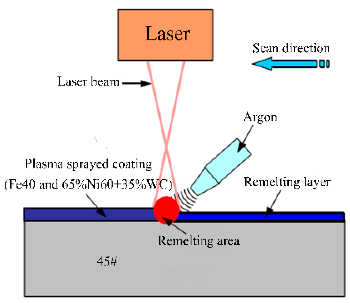
2. Experimental Work

2.1. Coating Preparation

The matrix material used in the experiment is a 45 steel. Before flame spraying, the surface of the substrate was polished with 400 mesh sandpaper, and then impurities such as oil on the surface were removed by acetone solution. The coating material is a cermet coating produced by Zhen Xing Metal Powder Co., Ltd., Chengdu, China. That is made of an iron-based alloy powder (Fe40) and a nickel-based tungsten carbide alloy powder (Ni60 + 35WC) mixed in the ratio of 9:1 (its chemical composition is given in Table 1. During flame spraying, the 0.4 mm Fe40 + Ni60 + 35WC cermet coating was sprayed on the surface of the 45 steel used spraying system self-manufactured by Fu Rui Technology Co., Ltd., Beijing, China. (the process parameters of flame spraying as shown in Table 2.) Using nano-SiC as a filler, and Ar as a shielding gas during remelting process. The nano-SiC was mainly used as the composite modified phase of nano-composite ceramic composites or nanostructure coating for its high strength, hardness, wear resistance, corrosion resistance, and other mechanical properties [15]. The nano-SiC powder was mixed into mushy with absolute ethyl alcohol and presented on the surface of flame coating—the thickness of which was about 150 μm. Then, it was dried and cured in a vacuum drying box at 120 °C for 1.5 h, and the laser remelting test was carried out after finishing the shape. A second heat treatment was carried by the AXL-600 AW laser remelting equipment produced by Ao Xin Laser Co., Ltd., Dongguan, China. The schematic diagram and related experimental parameters used during the laser remelting process are shown in Figure 1 and Table 3, respectively.
The prepared sample was cut into a cuboid measuring 15 mm × 10 mm × 6 mm in a wire-cutting machine tool: the cross-section of the sample was polished by metallographic abrasive papers and a homemade polishing fluid until a bright mirror effect was reached. To facilitate subsequent microstructural observations, a 4% nitric acid alcohol solution was selected as the etching solution to corrode the sample for about 5 s (the corrosion time was very short and had little effect on the interface elements).

2.2. Analysis and Characterisation

The microstructural features of the interface between the coating and the substrate were analysed by MLA650F field emission scanning electron microscopy (FESEM) (FEI, Hillsborough, OR, USA). The distribution of interfacial elements was analysed by examination of their energy spectra (EDS) and the phase of the coating was analysed by the Empyrean X-ray diffraction (equipped with a Cu-Kα radiation (λ = 0.15418 nm)) system (OLYMPUS, Tokyo, Japan). The microhardness was measured at the cross-section of the polished samples with an FM-700 type micro-hardness tester (Future-Tech Enterprise Inc., Holbrook, AZ, USA), under a loading of 1 kg and test distance of 0.05 mm for 10 s. Each test was repeated to give sample size n = 3 before averaging. Besides, the particles and holes on the coating surface were avoided as much as possible during measurement.

3. Results and Analysis

3.1. Phase Structure

Figure 2a shows the XRD patterns of the remelted coatings at different scanning speeds. The main phases of the surface are WC, W2C, M7C3, α-(Fe, Ni), M23C6, (Cr, Ni)3Si, and so on. In the process of plasma spraying and laser remelting, WC particles decomposed in the high-temperature environment as follows: WC → W + C, 2W + C → W2C [16], the decomposed C atoms will be combined with other elements to produce a cubic structure of M6C type carbide. For example, in the melted WC and Fe, Ni is generated (Fe, Ni)6C, and its dispersion is high. W2C has a dense hexagonal structure, and it was dispersed in the coating, playing a role in the dispersion of strengthening. M7C3 is a large hardened carbide structure (about 0.5 μm diameter), with a complex structure, and it is the hardening phase with high melting point and hardness. M23C6 is a smaller carbide (about 0.1 to 0.2 μm), with a face centred cubic structure [16]. It can be seen that the phase composition in the remelted layer is almost unchanged when the scanning speed is increased from 150 to 250 mm/min. The coatings mainly consisted of [Fe, Ni], Cr, WC, Cr7C3, Fe0.04Ni0.36, and other phases. After laser remelting, due to the addition of nano-SiC, new phases such as: Fe2Si, Cr2Si, and W2C phases appear. Additionally, from the figure we can see that the peak of WC is relatively small, which means that due to the decarburisation phenomenon (i.e., 2WC + O2 = W2C + CO2) [17] present during the remelting process, most of them are decomposed and transformed to the W2C phase. Besides, some supersaturated solid solution phases and metal carbides, generated by the appearance of elemental Cr, play the role of solid solution strengthening and dispersion strengthening.
According to research [18], the broadening effect and microstrain caused by grain refinement are in agreement with the Lorentz and Gauss functions, respectively. In order to observe the effect of scanning speed on grain refinement objectively, a comparison of the broadening phenomenon of the first main peak (42° to 45° diffraction angle) is shown in Figure 2b. The faster the scanning speeds, the wider the half-height (FWHM). Therefore, it can be understood that the increase of the scanning speed can make the eutectic microstructure of the remelted layer finer and decrease the grain size correspondingly by the Scherrer and Wilsoh equation [19]. Moreover, the Hall-Petch [20] relationship (σs = σ0 + Kd½) can explain why the fine grains can not only improve the ductility and toughness of the material, but also improve the strength thereof.

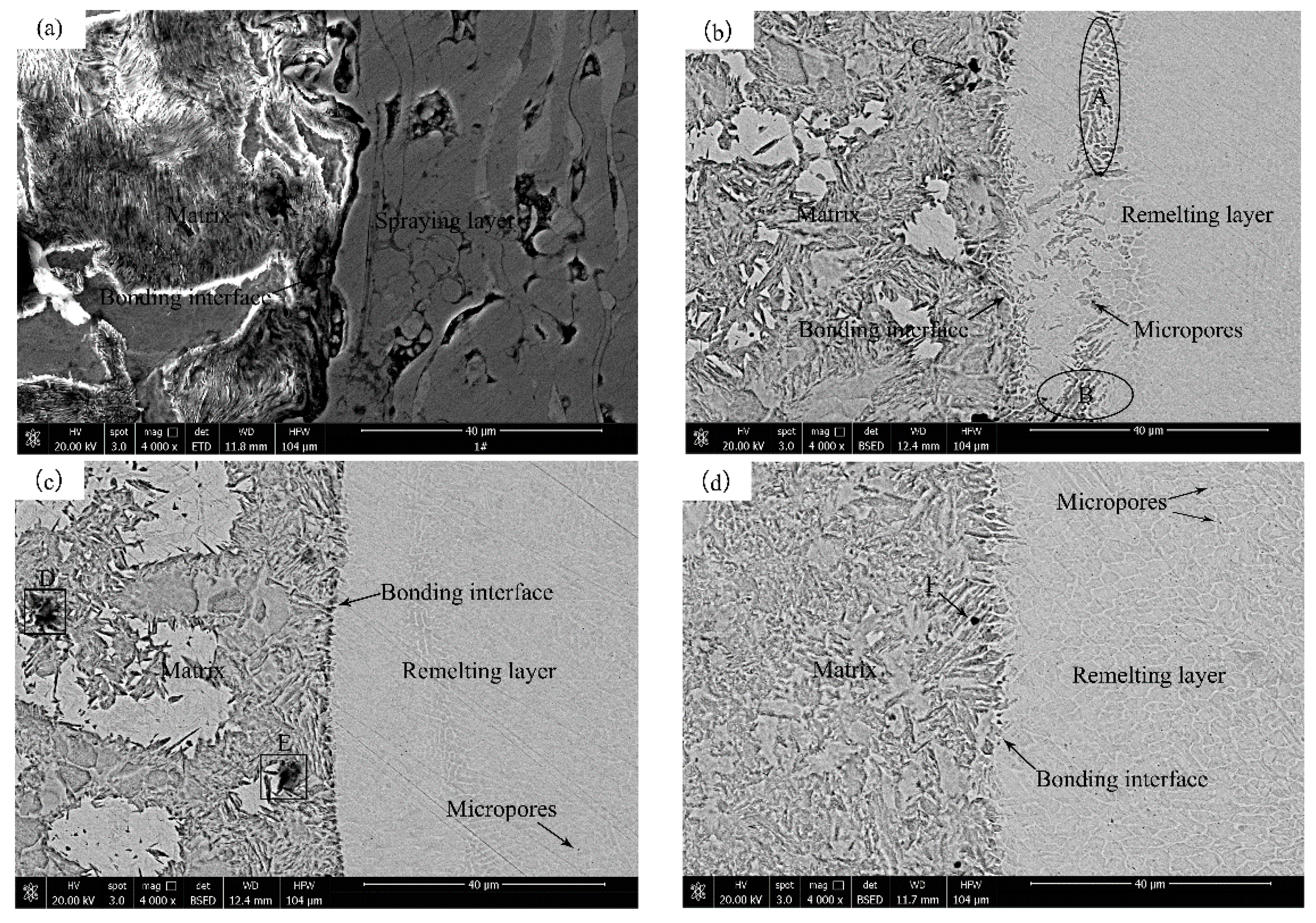
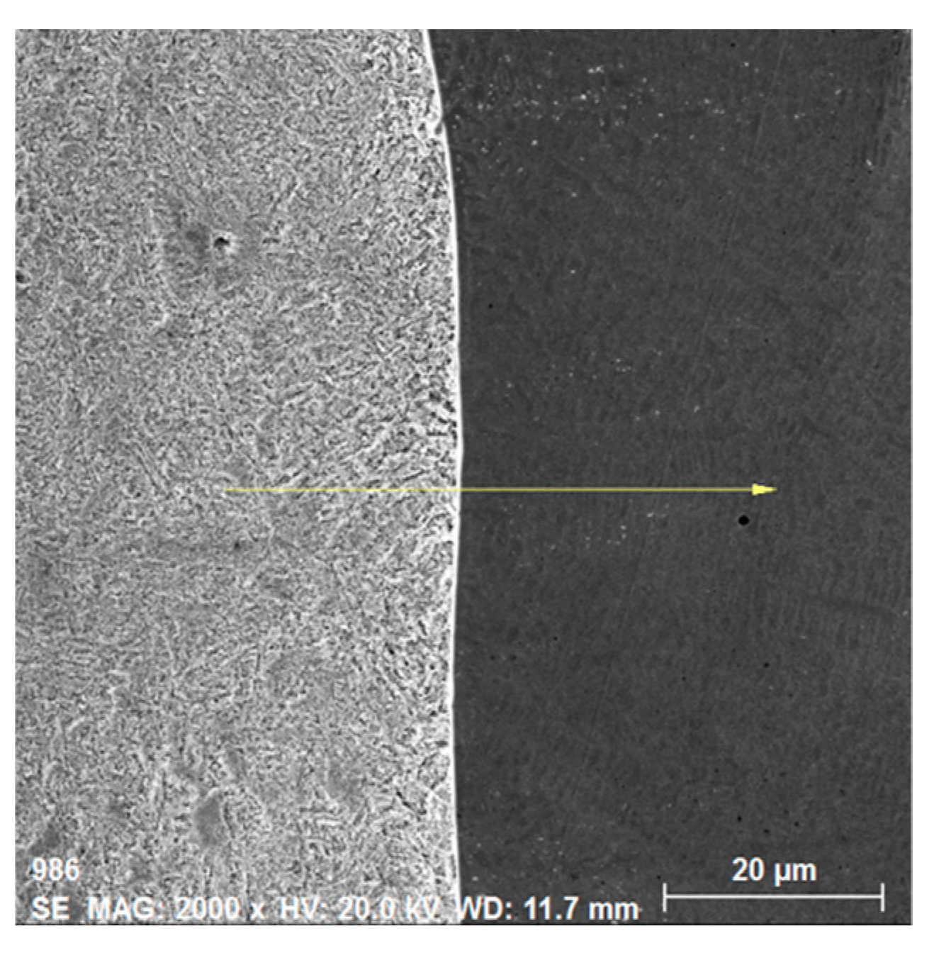
3.2. Interface Morphology

Figure 3 is the SEM photos for the interface morphology. Figure 3a shows that the interface between the as-sprayed coating and the matrix are riddled with large pores and interlayer cracks, and more cracks and pores exist between the layers as well. The coating of such a layered structure is prone to engender adhesion wear under high-speed friction, and exerts a significant influence on the coating performance and service life. In addition, some of the spraying particles are stacked and not fully filled at the bonding interface, which leads to appearance of rigid connection between the matrix and coatings. Hence, the coating interface is a typical mechanical bond, which greatly reduces the bond strength between the spray coating and the matrix. Figure 3b–d shows the SEM images of the remelted layers: after processing at different scanning speeds, the coatings are smooth and compact without fine cracks, most of the internal defects are eliminated, and the density of coatings are improved. Besides, the surface is relatively flat, the original lamellar structure at the cross-section has disappeared, and the coating and matrix forms a solid metallurgical combination. When the scanning speed is 150 mm/min, the interface junction appears two interface lines. The coating contains a small amount of micropores, and the micro- structure of regions A and B is the same. This can be explained by the lower scanning speed and the pool-mixing taking too long, making the coating absorb excessive energy and decreasing the dilution of the substrate to the remelted layer. The formation of organisational structures that are similar to the regions A and B by the excessive melting of the coating and substrate reduced the strength and hardness of the coating to some extent. When the scanning speed was 200 mm/min, the micropores in the coating were reduced in number, and the black substance in regions D and E remained uncleaned and oxidised under experimental corrosion conditions. When the scanning speed was 250 mm/min, unavoidable micropores still exist in the coating, and the numbers of the micropores are higher than that at first two scanning speeds. The micropores may be caused by the bubbles in the molten liquid or the slag, which cannot escape in time to cool and solidify, resulting in microporous defects in the coating. The reasons for the difference between the coating and regions F or C, with regard to the formation of micropores, is that there is a small amount of elemental segregation in the rapid cooling after laser remelting, which hinders the growth of the grain boundary front of the solidified part and results in the formation of tiny holes. In addition, the scanning speed exerts a significant influence on the surface heating time of the coating. Assuming that the coordinates of the centre of the laser beam are fixed, and the laser spot is round (Figure 4), and:
s = v t
s 2 = 4 ( r 2 x 2 )
( v t ) 2 = 4 ( r 2 x 2 )
t 2 / ( 2 r / v ) 2 + x 2 / r 2 = 1
Finally, the relationship between the laser irradiation time and the scanning speed can be deduced:
t 2 ( D v ) 2 + x 2 ( D 2 ) 2 = 1
where t is the laser irradiation time of point P, s; s is the swept distance at point P (AB) (Figure 4), mm; x is the distance from point P to the spot centre, mm; D is the beam diameter, mm; and V is the laser scanning speed, mm/s.
According to Equation (5), the time-distance curve for different scanning speeds, at a certain laser power and spot diameter, can be plotted as Figure 5. The larger the scanning speed, the smoother the curve. Compared with the time curve, the heated area throughout the whole surface becomes more uniform with the increasing of the scanning speed. Thus, in order to ensure the uniformity of heat energy over the coating surface, a larger scanning speed is needed as far as the adequate fusion energy exists in the interface between the substrate and the coating. However, the scanning speed is restricted by the thicker coating. The thicker the coating, the lower the requirements on the scanning speed to meet the required penetration of the coating and achieve the metallurgical bonding. The coating can reach optimal performance at the scanning speed of 200 mm/s, everything considered.

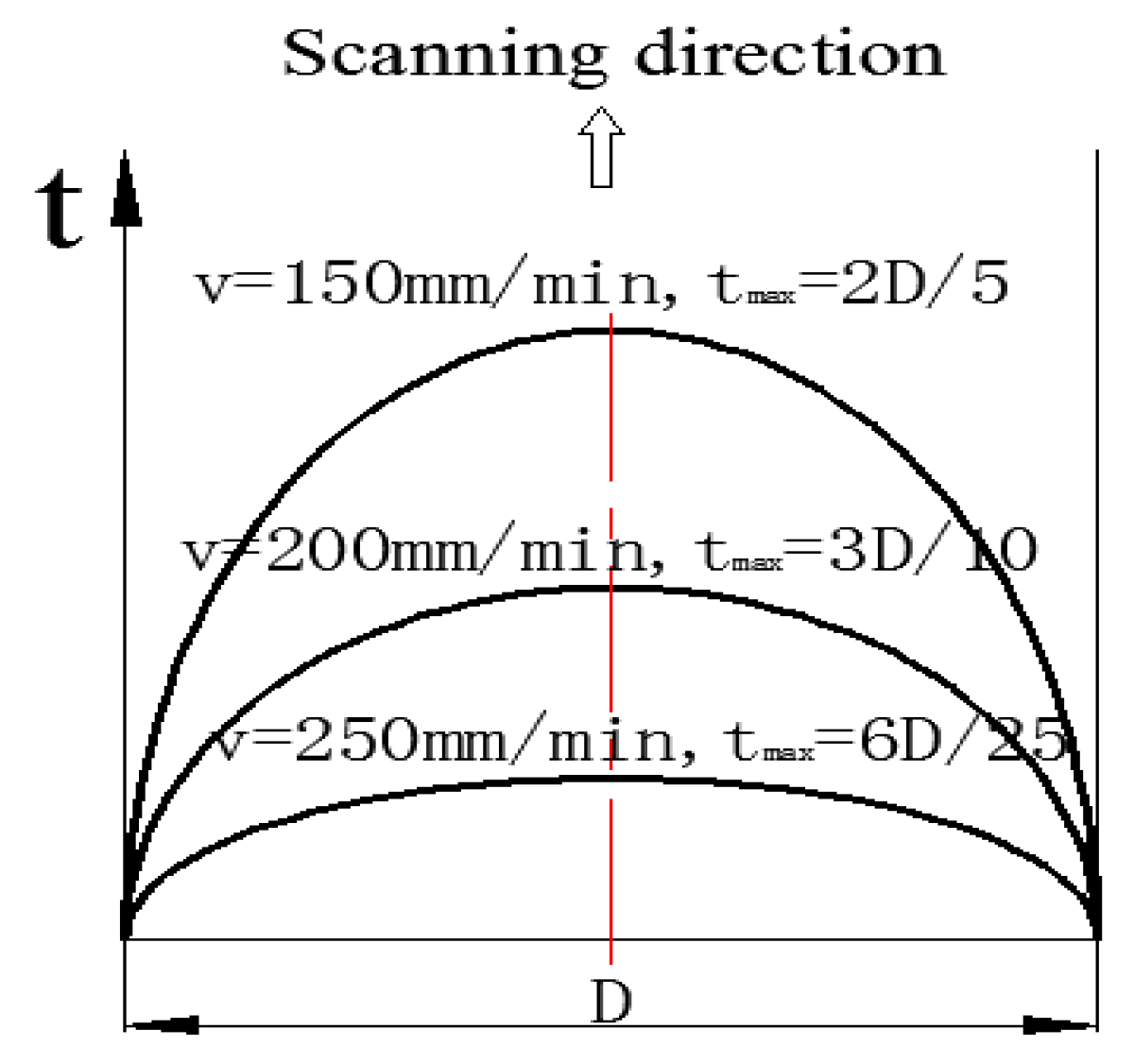
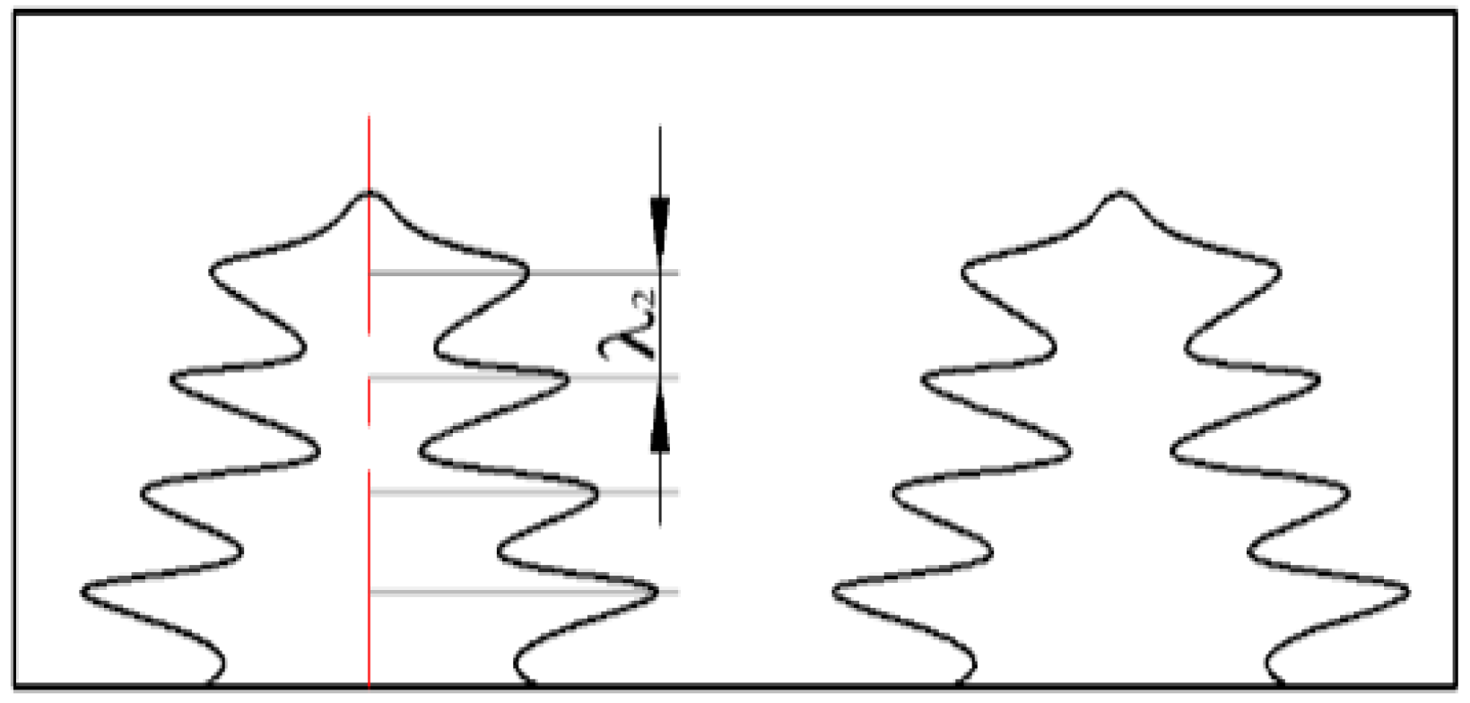
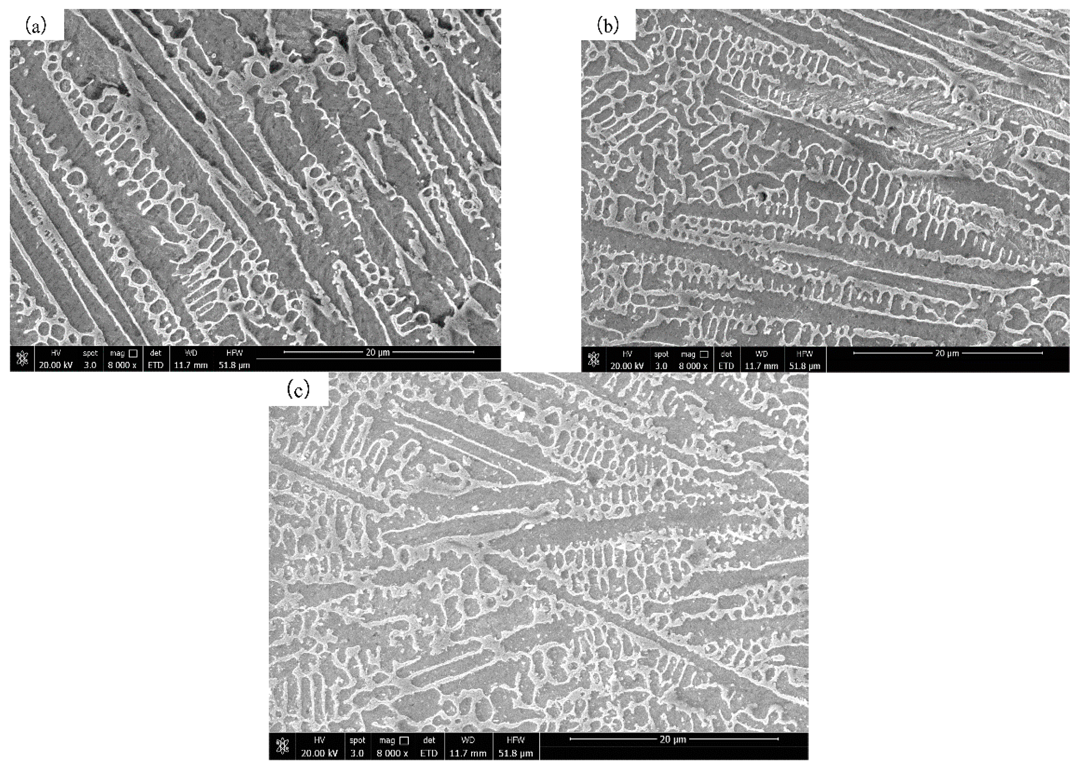
3.3. Dendrite Growth Behaviour Analysis

Based on the Image-Pro Plus software, the line transect method is used to measure the secondary dendrite spacing, as shown in Figure 6. To measure the secondary dendrites, each metallographic picture is assessed at four measuring positions and the average is taken. Figure 7 shows SEM imagery of the secondary dendrite spacing measurement. It can be seen from Figure 7 that the microstructure of the coating is mainly composed of well-developed dendritic structures. Normally, the quality of the solidification structure can be assessed by the primary dendritic spacing and the secondary dendritic spacing. Among them, the primary dendrite spacing exerts an important influence on the mechanical properties, and the secondary dendrite arm spacing has a direct influence on the segregation of components, the secondary phase, and the distribution of the microscopic holes. Table 4 shows the results of the secondary dendrite spacing. It can be seen that the larger the scanning speed, the smaller the secondary dendrite spacing, and the smaller the dendritic structure, which indicates that the precipitation phase, the ordered domain and other components, and the substructure size is correspondingly reduced. This is mainly because the greater the scanning speed, the less energy the coating absorbs from the laser. A large number of crystal nuclei in the melt pool do not have insufficient time to grow and solidify, during the rapid solidification process. In addition, according to the formula proposed by Kirkwood [21] (Equation (2)), the secondary dendrite spacing depends on the material cooling rate or local solidification time directly, which means the slower the cooling rate, or the shorter the local solidification time, the smaller the secondary dendrite spacing. Therefore, combined with the characteristics of laser remelting (i.e., rapid heating and rapid cooling), the faster the scanning speed, the shorter the cooling time, the smaller the corresponding dendrite spacing, and the finer the organisational structure.
λ 2 = β t 1 / 3
where λ2 is the secondary dendritic spacing, β is the dendrite solidification time, and t is a constant.
In the range 100–150 mm/min it can clearly be seen that the scanning speed is low; the rate of laser energy absorption is higher; the cooling rate of the coating is slower; the cladding area can absorb more heat; the melting duration is longer—in which the crystal bubble has enough time to grow up—therefore the lattice volume is large; the number is small and the microstructure is relatively coarse. Lattice distortion occurred in the cladding area of the Figure 7a coating, and its structure was similar to a “fish bone.” In the range 200–250 mm/min, the scanning speed is high, and the cladding area is subjected to rapid melting and solidification. The gradient of temperature changed greatly, resulting in a large number of crystal nuclei and more lattice. The distance between the internal lattices decreased after the grain refinement of the remelted coating. Therefore, the microstructure of the Figure 7b,c coating is more intensive [22,23].

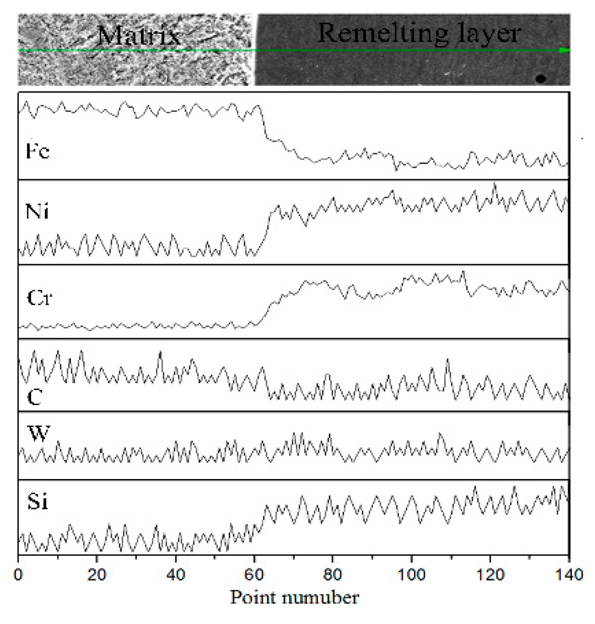
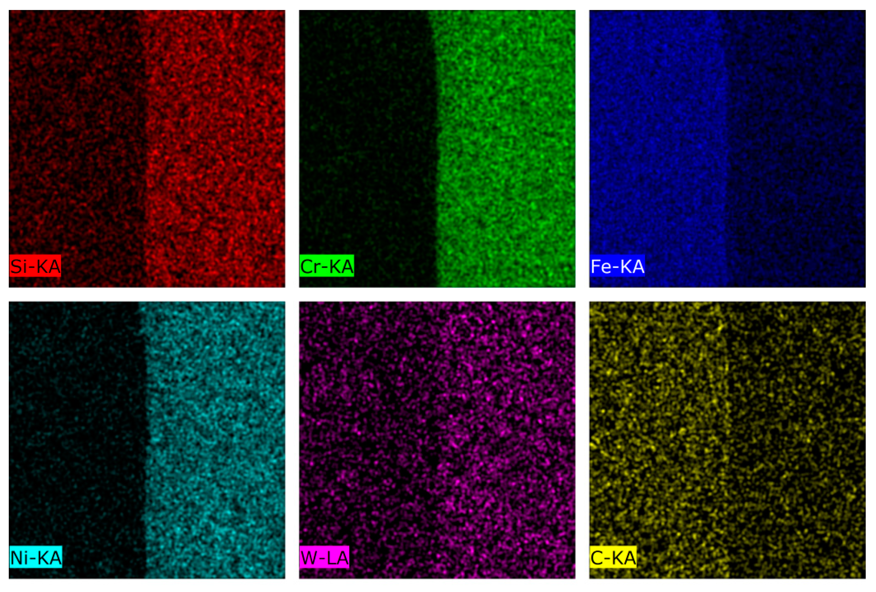
3.4. Interface Elements
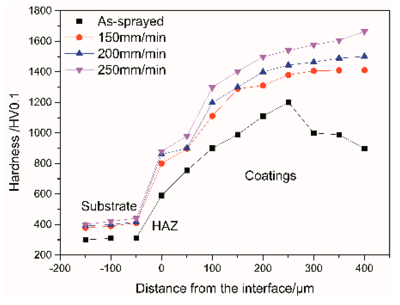
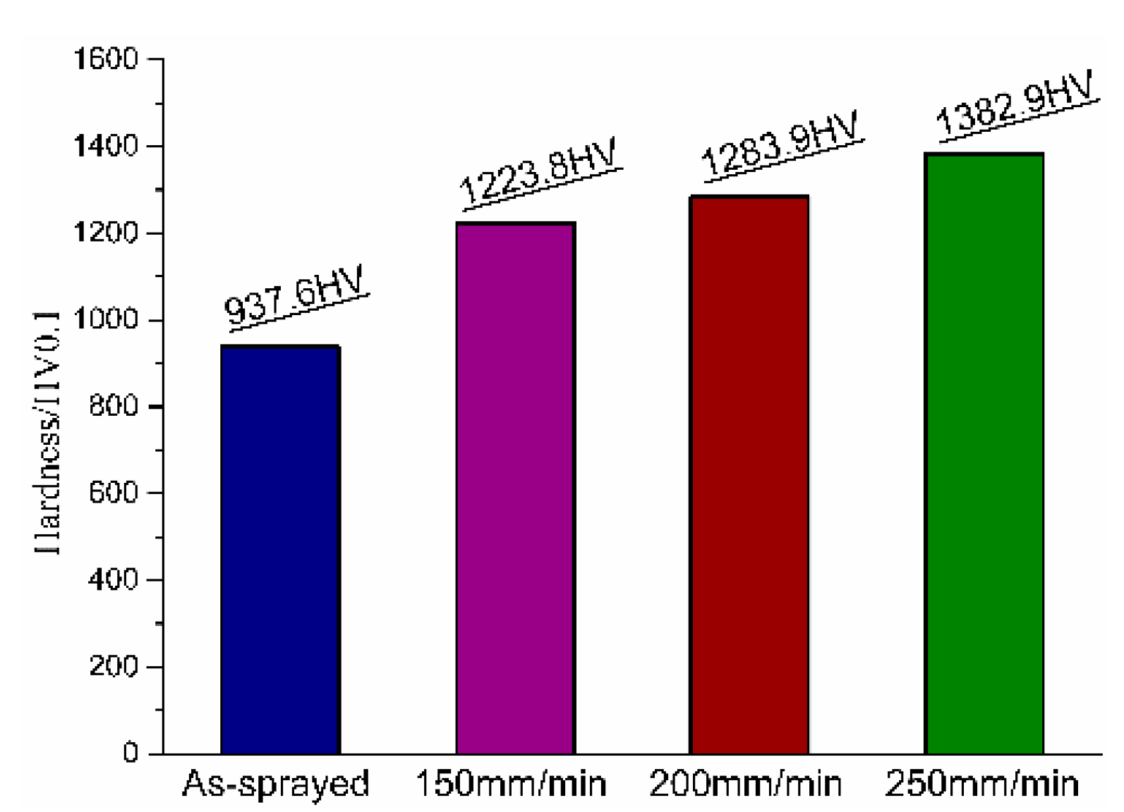
The interface EDS scanning position at 200 mm/s is shown in Figure 8. Figure 9 shows the line scan analysis results at the scanning speed is 200 mm/s and the scanning-line length is 50 μm. It can be seen that the atomic content of Ni, Cr, and Si in the coating is higher, and inter-diffusion occurs at the interface. The content of each element gradually decreases towards the interior of the matrix, resulting in the gradient hardness of the coating. Simultaneously, the presence of Cr in the coating is beneficial to the improvement of the microhardness and corrosion resistance of the coating. Elemental Si can refine the coating grain structure to improve the oxidation resistance of the coating. By contrast, elemental C diffuses slightly from the substrate to the remelting layer, which indicates that the diffusion of C mainly plays a dominant role for the interfacial diffusion. The elemental Fe content is gradually reduced from the substrate to the remelting layer, indicating that the Fe is mainly diffused from the matrix to the remelting layer. Since the distribution of elemental W is equivalent between the matrix and coating, it can be stated that the diffusion of W is not obvious. In addition, the atomic diffusion is an unsteady process during laser remelting. According to the Arrhenius equation [24] (Equation (7)), the diffusion coefficient D increases exponentially with the temperature T. Increasing the thickness of the atomic diffusion layer is beneficial to improving the bonding strength between the coating and substrate. As laser remelting is a rapid quenching process and the temperature therein is very high, the diffusion coefficient is much larger than that at 293 K (room temperature). Surface diffusion occurs mainly in the remelting process, the temperature gradually returned to normal after remelting, and the degree of atomic diffusion was very low.
D = D 0 exp ( Q R T )
where D is the diffusion constant, R is the ideal gas constant (8.314 J·mol−1·K−1), Q is the diffusion activation energy, and T is the temperature.
Figure 10 shows the plane scan analysis results (from Figure 8). It can be seen that the coating contains more Si, Cr, and Ni and Fe and C are comparatively gathered in the matrix, whereas W shows dispersion distribution, and the enrichment is not obvious. These results are consistent with the results of line-scan analysis. Finally, based on the above research and analysis, it can be concluded that a certain metallurgical bonding between coating and matrix is formed during the diffusion process.

3.5. Micro-Hardness

Figure 11 shows the micro-hardness curves obtained at different scanning speeds. It can be seen that the micro-hardness increases with depth from the bonding interface to the coating surface. When the scanning speed is low, the remelted layer shows coarse microstructure and low micro-hardness due to the higher absorbed energy. When the scanning speed increases, the dendrite spacing of the remelted layer is relatively small due to the lower absorbed energy and higher solidification rate, which finally increases the hardness. Therefore, the increase of the scanning speed helps to refine the grains to some extent. However, it must be stressed that the excessively high scanning speed might result in the hardness decreasing because the existence time of the molten pool is too short. Figure 12 shows the average micro-hardness of the coating formed at different scanning speeds. The average hardness of the flame spray is about 937.6 HV, and the average hardness of the remelted layer at scanning speeds of 150, 200, and 250 mm/s is about 1223.8, 1283.9, and 1382.9 HV, respectively. The maximum hardness of the remelted layer increases by 47%. Therefore; the greater the scanning speed, the higher the hardness. This may be explained by the interaction between the Ni, Cr, Fe, Si, C, and other elements therein, the fine-grained strengthening by the grain refinement, and the solution strengthening by the formation of the supersaturated solid solution during the rapid solidification process. In summary, when the laser scanning speed increases, the microstructure of the remelting zone is refined and the hardness increases.

4. Conclusions

The flame sprayed Fe-based Ni/WC cermet coating l with laser remelting was performed. The influence of different scanning speeds on the interface behavior of remelting coating was investigated. The following conclusions can be obtained:
  • The interface of the flame sprayed coating showed typical mechanical bonding features and contained several holes and obvious interlayer cracks. After laser remelting, the coatings were smooth and dense due to the existence of well-developed dendrite structures and metallurgical bonding formed during the diffusion process and could reach optimal performance at 200 mm/s. Despite the existence of initial phases in the spray coatings, new phases such as Fe2Si, Cr2Si, and W2C appeared in the remelted layers.
  • The secondary dendritic spacings of the scanning speed (150, 200, 250 mm/s) were 1.106, 1.0496, 0.6209 μm, respectively. With the increase of scanning speed, the half-peak height (FWHM) and average grain size became wider and smaller, respectively. The phenomenon of grain refinement was obvious.
  • After laser remelting, the coatings mainly consisted of [Fe, Ni], Cr, WC, Cr7C3, Fe0.04Ni0.36, and other phases. The maximum hardness of the remelting layer increases by 47%. The improvement of the micro-hardness could be explained by the interaction between Ni, Cr, Fe, Si, C, and other elements therein, the fine-grained strengthening by the grain refinement, and the solution strengthening by the formation of the supersaturated solid solution during the rapid solidification process.

Author Contributions

Thesis, overall framework, research design, article revision, Y.Z.; data cleaning, data collection, production charting, drafting of papers, L.W.; Data analysis, W.H.

Funding

The research was financially supported by National Natural Science Foundation of China (Grant No. 51565017), Tribology technology and application of high end bearings -- National Open Project for local joint engineering laboratory (Grant No. 201713), Natural Science Foundation of Jiangxi province (Grant No. 2012BAB206026), Jiangxi Provincial Education Department (Grant No. GJJ14424).

Conflicts of Interest

The authors declare no conflict of interest.

References

  1. Zheng, C.; Liu, Y.; Qin, J.; Chen, C.; Ji, R. Wear behavior of HVOF sprayed WC coating under water-in-oil fracturing fluid condition. Tribol. Int. 2017, 115, 28–34. [Google Scholar] [CrossRef]
  2. Thiem, P.G.; Chornyi, A.; Smirnov, I.V.; Krüger, M. Comparison of microstructure and adhesion strength of plasma, flame and high velocity oxy-fuel sprayed coatings from an iron aluminide powder. Surf. Coat. Technol. 2017, 324, 498–508. [Google Scholar] [CrossRef]
  3. Yin, B.; Zhou, H.D.; Yi, D.L.; Chen, J.M.; Yan, F.Y. Microsliding wear behaviour of HVOF sprayed conventional and nanostructured WC–12Co coatings atelevatedtemperatures. Surf. Eng. 2010, 26, 469–477. [Google Scholar] [CrossRef]
  4. Yu, H.L.; Zhang, W.; Wang, H.M.; Yin, Y.L.; Ji, X.C.; Zhou, K.B. Comparison of surface and cross-sectional micro-nano mechanical properties of flame sprayed NiCrBSi coating. J. Alloys Compd. 2016, 672, 137–146. [Google Scholar] [CrossRef]
  5. Matikainen, V.; Bolelli, G.; Koivuluoto, H.; Sassatelli, P.; Lusvarghi, L.; Vuoristo, P. Sliding wear behaviour of HVOF and HVAF sprayed Cr3C2 -based coatings. Wear 2017, 388, 57–71. [Google Scholar] [CrossRef]
  6. Chen, X.Y.; He, X.Y.; Suo, X.K.; Huang, J.; Gong, Y.F.; Liu, Y.; Li, H. Effect of surface topological structure and chemical modification of flame sprayed aluminum coatings on the colonization of Cylindrotheca closterium on their surfaces. Appl. Surf. Sci. 2015, 388, 385–391. [Google Scholar] [CrossRef]
  7. Puranen, J.; Laakso, J.; Honkanen, M.; Heinonen, S.; Kylmalahti, M.; Lugowski, S.; Coyle, T.W.; Kesler, O.; Vuoristo, P. High temperature oxidation tests for the high velocity solution precursor flame sprayed manganese–cobalt oxide spinel protective coatings on SOFC interconnector steel. Int. J. Hydrogen Energy 2015, 40, 6216–6227. [Google Scholar] [CrossRef]
  8. González, R.; Cadenas, M.; Fernández, R.; Cortizo, J.L.; Rodríguez, E. Wear behaviour of flame sprayed NiCrBSi coating remelted by flame or by laser. Wear 2007, 262, 301–307. [Google Scholar] [CrossRef]
  9. Wu, Y.N.; Zhang, G.; Feng, Z.C.; Zhang, B.C.; Liang, Y.; Liu, F.J. Oxidation behavior of laser remelted flame sprayed NiCrAlY and NiCrAlY-Al2O3 coatings. Surf. Coat. Technol. 2001, 138, 56–60. [Google Scholar]
  10. Yuan, Y.Z.; Zhu, Y.L.; Liu, Z.Y.; Chuang, Y.Z. Laser remelting of flame sprayed Al2O3 ceramic coatings and subsequent wear resistance. Mater. Sci. Eng. A 2000, 291, 168–172. [Google Scholar]
  11. Gao, X.S.; Tian, Z.J.; Liu, Z.D.; Shen, L.D. Interface characteristics of Al2O3-13% TiO2 ceramic coatings prepared by laser cladding. Trans. Nonferrous Met. Soc. China 2012, 22, 2498–2503. [Google Scholar] [CrossRef]
  12. Ciubotariu, C.R.; Frunzăverde, D.; Mărginean, G.; Șerban, V.A.; Bîrdeanu, A.V. Optimization of the laser remelting process for HVOF-sprayed Stellite 6 wear resistant coatings. Opt. Laser Technol. 2016, 77, 98–103. [Google Scholar] [CrossRef]
  13. Wang, Y.; Li, C.G.; Guo, L.X.; Tian, G. Laser remelting of flame sprayed nanostructured Al2O3-TiO2 coatings at different laser power. Surf. Coat. Technol. 2010, 204, 3559–3566. [Google Scholar] [CrossRef]
  14. Jia, Z.X.; Li, J.Q.; Liu, L.J.; Liu, Y.W.; Wang, Y.Q.; Li, H.L. Influence and application of laser parameters on unit of H13 steel by laser remelting process. Int. J. Adv. Manuf. Technol. 2015, 79, 551–568. [Google Scholar] [CrossRef]
  15. Zakaria, H.M. Microstructural and corrosion behavior of Al/SiC metal matrix composites. Ain Shams Eng. J. 2014, 5, 831–838. [Google Scholar] [CrossRef]
  16. Dahal, J.N.; Neupane, D.; Poudel, T.P. Synthesis and magnetic properties of 4:1 hard-soft SrFe12O19-La1- xSrxMnO3 nanocomposite prepared by auto-combustion method. AIP Adv. 2019, 9, 075308. [Google Scholar] [CrossRef]
  17. Hemmati, I.; Ocelík, V.; Hosson, J.D. The effect of cladding speed on phase constitution and properties of AISI 431 stainless steel laser deposited coatings. Surf. Coat. Technol. 2011, 205, 5235–5239. [Google Scholar] [CrossRef] [Green Version]
  18. Ungár, T.; Langford, J.I.; Cernik, R.J.; Vörös, G.; Pflaumer, R.; Oszlányi, G.; Kovàcs, I. Microbeam X-ray diffraction studies of structural properties of polycrystalline metals by means of synchrotron radiation. Mater. Sci. Eng. A 1998, 247, 81–87. [Google Scholar] [CrossRef]
  19. Klug, H.P.; Alexander, L.E. X-Ray Diffraction Procedures for Polycrystalline and Amorphous Materials, 2nd ed.; Wiley-VCH: New York, NY, USA, 1974; p. 992. [Google Scholar]
  20. Anderson, P.M.; Li, C. Hall-Petch relations for multilayered materials. Nanostructured Mater. 1995, 5, 349–362. [Google Scholar] [CrossRef]
  21. Kirkwood, D.H. Three-dimensional growth morphologies in diffusion-controlled channel growth. Phys. Rev. E 1997, 55, 7789–7792. [Google Scholar]
  22. Dahal, J.N.; Ali, K.S.S.; Mishra, S.R.; Alam, J. Structural, magnetic, and mössbauer studies of transition metal-doped Gd2Fe16Ga0.5TM0.5 intermetallic compounds (TM = Cr, Mn, Co, Ni, Cu, and Zn). Magnetochemistry 2018, 4, 54. [Google Scholar] [CrossRef]
  23. Myung, S.T.; Izumi, K.; Komaba, S.; Sun, Y.K.; Yashiro, H.; Kumagai, N. Role of alumina coating on Li-Ni-Co-Mn-O particles as positive electrode material for lithium-ion batteries. Chem. Mater. 2005, 17, 3695–3704. [Google Scholar] [CrossRef]
  24. Huang, J.H. The Diffusion in Metals and Alloys; Metallurgical Industry Press: Beijing, China, 1996; pp. 1–3. (In Chinese) [Google Scholar]
Figure 1. Schematic diagram of laser remelting.
Coatings 09 00677 g001
Figure 2. Patterns of (a) As-sprayed coating and different scanning speed remelting coating, and (b) the first primary peak.
Coatings 09 00677 g002
Figure 3. SEM of interface morphology at: (a) flame spraying; (b) 150 mm/min; (c) 200 mm/min; (d) 250 mm/min.
Coatings 09 00677 g003
Figure 4. Heating process profiles at point P of coating surface.
Coatings 09 00677 g004
Figure 5. Heating time profiles at point P of coating surface vertical to the scanning direction.
Coatings 09 00677 g005
Figure 6. The measurement process of the secondary dendrite arm spacing using the linear intercept method.
Coatings 09 00677 g006
Figure 7. SEM of measuring the secondary dendrite arm spacing at: (a) 150 mm/min; (b) 200 mm/min; (c) 250 mm/min.
Coatings 09 00677 g007
Figure 8. Interface EDS scanning position at 200 mm/s.
Coatings 09 00677 g008
Figure 9. Line scan analysis results at 200 mm/s.
Coatings 09 00677 g009
Figure 10. Plane scan analysis results at 200 mm/s.
Coatings 09 00677 g010
Figure 11. Micro-hardness changes through the cross-section.
Coatings 09 00677 g011
Figure 12. Average coating micro-hardness.
Coatings 09 00677 g012
Table 1. Main chemical composition of the coated powder material (wt.%).
ElementNiCrBSiCFeWC
Fe408.916.42.11.9<0.5Trace-
65% Ni60 + 35% WCTrace17.23.14.10.939.335
Table 2. The main process parameters of flame spraying.
Air PressureOxygen PressureAcetylene PressureSpraying DistanceSpraying Speed
>0.4 Mpa0.7 Mpa0.1 MPa200 mm24 m/min
Table 3. Parameters of laser remelting process.
Laser Power P/ WScanning Speed V/(mm/min)Spot Diameter D/mmLaser Pulse T/ms
600150210
600200210
600250210
Table 4. Measurement results of secondary dendrite arm spacing.
Scanning Speed mm/minSecondary Dendrite Arm Spacing /um
D1D2D3D4Average Value
1501.03071.17781.30750.90811.1060
2001.30160.88181.05770.95721.0496
2500.81310.81530.84491.01020.6209

