Article

Corrosion Damage Mechanism of TiN/ZrN Nanoscale Multilayer Anti-Erosion Coating

1
Science and Technology on Plasma Dynamics Laboratory, Air Force Engineering University, Xi’an 710038, China
2
School of Materials Science and Engineering, Chang’an University, Xi’an 710064, China
3
School of Mechanical Engineering, Xi’an Jiaotong University, Xi’an 710049, China
*
Author to whom correspondence should be addressed.
Coatings 2018, 8(11), 400; https://doi.org/10.3390/coatings8110400
Submission received: 16 September 2018 / Revised: 17 October 2018 / Accepted: 10 November 2018 / Published: 13 November 2018
(This article belongs to the Special Issue From Metallic Coatings to Additive Manufacturing)

Abstract

:
TiN/ZrN multilayers can effectively improve the erosion resistance of metals, particularly titanium alloys employed in aero engines. To explore the corrosion damage mechanism of TiN/ZrN nanoscale multilayers (nanolaminate), a novel [TiN/ZrN]100 nanolaminate coating was deposited on Ti-6Al-4V alloys by multi-arc ion plating method. Salt spray corrosion tests and hot corrosion experiment were carried out to evaluate the corrosion resistance of the coating. The corrosion and damage mechanisms were explored with the help of detailed microstructure, phase composition and element distribution characterizations. The salt spray corrosion tests showed that the [TiN/ZrN]100 nanolaminate coating possessed good corrosion resistance, which protected substrate against the corrosion. The low temperature hot corrosion tests showed that the oxidation occurred on the surface of the coating, which improved the oxidation resistance of the sample. However, the oxidized droplets squeezed the coating, and destroyed the oxidized layers. As a result, the coating was peeled off from the substrate. The research highlights the corrosion resistance of the novel TiN/ZrN nanolaminate coating and offers a support for their application in engine compressor blade.

1. Introduction

Advanced aero engine compressor blades are mostly made up by high strength titanium alloys [1]. They are generally subjected to harsh environments, leading to serious due to erosion and corrosion damages [2,3]. This significantly limits the service of the aircraft, especially transport aircrafts and helicopters serving in deserts or oceans [4].
Anti-erosion coatings are good candidates to protect the compressor blades [5,6]. TiN/ZrN multilayer coatings have good mechanical properties [7]. They can improve the erosion resistance of metals [8]. However, the effect of TiN/ZrN coatings on the corrosion resistance of titanium alloys in extreme environments requires further work.
The corrosion behaviors of TiN and ZrN coating in salt spray environment and sodium chloride solution were studied by Chou [9], Chen [10] and Brown [11]. The result showed that the controlling parameters for TiN are thickness and defect content, and for ZrN the oxidation process of the nitride [9,10,11]. As for the hot corrosion test, researchers focus mostly on the temperature below 100 °C or higher than 500 °C. The research for coatings serving in low pressure compressor environment is rarely reported.
In this research, the nanoscale multilayer (nanolaminates) coatings of [TiN/ZrN]100 were prepared by multi-arc ion plating on a Ti-6Al-4V alloy. Their performance and damage behaviors were studied by salt spray corrosion test and hot corrosion tests. Scanning electron microscope (SEM) and X-ray diffractometer (XRD) techniques were used to understand the morphological characteristics of samples in corrosion environment.
The results show that, under 576 h salt spray test, the titanium alloy is pitting and oxidation products appear, while the TiN/ZrN nanoscale multilayer coating remains stable in morphology and composition. Under 88 h hot corrosion, the oxidation occurred on the surface of the coating, which prevented further oxidation of the material. However, the oxidative expansion of the droplets caused mechanical damage and extensive peeling of the coating.

2. Materials and Methods

The annealed Ti-6Al-4V titanium alloy was used as substrate (50 mm × 20 mm × 5 mm). Its chemical composition is listed in Table 1. Figure 1 shows the XRD diffractogram of Ti-6Al-4V alloy. After the polishing procedure, the surface roughness Ra was less than 0.02 μm (SJ-201P Roughmeter, Mitutoyo, Kawasaki, Japan). Deionized water, acetone and alcohol were used for ultrasonic cleaning. Nanolaminate coatings were prepared on the surface of Ti-6Al-4V alloy by using a multi-arc ion plating equipment. The processing parameters of the coating are listed in Table 2.
TiN/ZrN nanolaminate coatings were prepared by multi-arc ion plating method, as schematically shown in Figure 2. The modulation period was 50, and the thickness ratio of TiN layer to ZrN layer was 1:1. The targets were 99.99% purity Ti and Zr (the diameter is 100 mm and the thickness is 40 mm, 20 mm away from substrate), and the reaction gas was 99.999% pure N2. Controlled vacuum chamber pressure was less than 2 × 10⁻³ Pa before deposition. After adding −1000 V bias voltage to clean the substrate, the Ti layer with a thickness of 1 μm was deposited (bias voltage −200 V, Ar 0.2 Pa). During the deposition, N2 pressure was controlled at 1.0 Pa. Cathode bias voltage was −100 V, and arc current 100 A. The deposition rate of the coating was about 100 nm/min.
The salt spray corrosion was carried out inside the YWX-015 salt spray corrosion system (Changzhou Ke Mei Experimental Instrument Co., Ltd., Changzhou, China). The samples were placed in a chamber at 35 °C under an aqueous spray (a 5 wt.% sodium chloride solution with a pH between 6.8 and 7.2) at a rate of 1–3 mL/h·80 cm2. The total spay time was 576 h, and the spray (24 h)-drying (24 h) procedure was alternatively conducted for 12 cycles. The surface of samples was observed by scanning electron microscope (SEM, TESCAN-MIRAⅢ, TESCAN ORSAY HOLDING, a.s., Brno-Kohoutovice, Czech Republic), and the composition was analyzed by X-ray diffractometer (XRD, Philips X’pert, Royal Dutch Philips Electronics Ltd., Amsterdam, the Netherlands).
Low temperature hot corrosion tests were performed on the TiN/ZrN nanolaminate coatings and the uncoated substrate with the same size inside a muffle furnace. A hot corrosion cycle commenced by coating 2 mg/cm2 salt film of Na2SO4/NaCl (95:5, w/w) mixture, and then exposing the samples at 300 °C for 4 h. The samples were cooled down in static air, and were washed by distilled and deionized water. After being dried, the tested samples were weighed carefully. After that, a fresh salt film was recoated prior to the next cycle in furnace. The total exposure time was 88 h. The sensitivity of the balance used in the work was 0.1 mg. The value of mass loss was calculated based on Equation (1).
δ G = ( m i m 0 ) / S
where δG is the mass loss of the sample; mi is the weight after hot corrosion; m0 is the weight before the test; and S is the superficial area of the sample. SEM, EDS and XRD were carried out to analyze the results.
SEM and EDS analysis were carried out by TESCAN-MIRAⅢ. The XRD equipment used for the analysis was Philips X’pert diractometer (Royal Dutch Philips Electronics Ltd., Amsterdam, the Netherlands) equipped with, Cu Kα, graphite monochromator. The operating voltage was 40 kV and the current 40 mA.

3. Results and Discussion

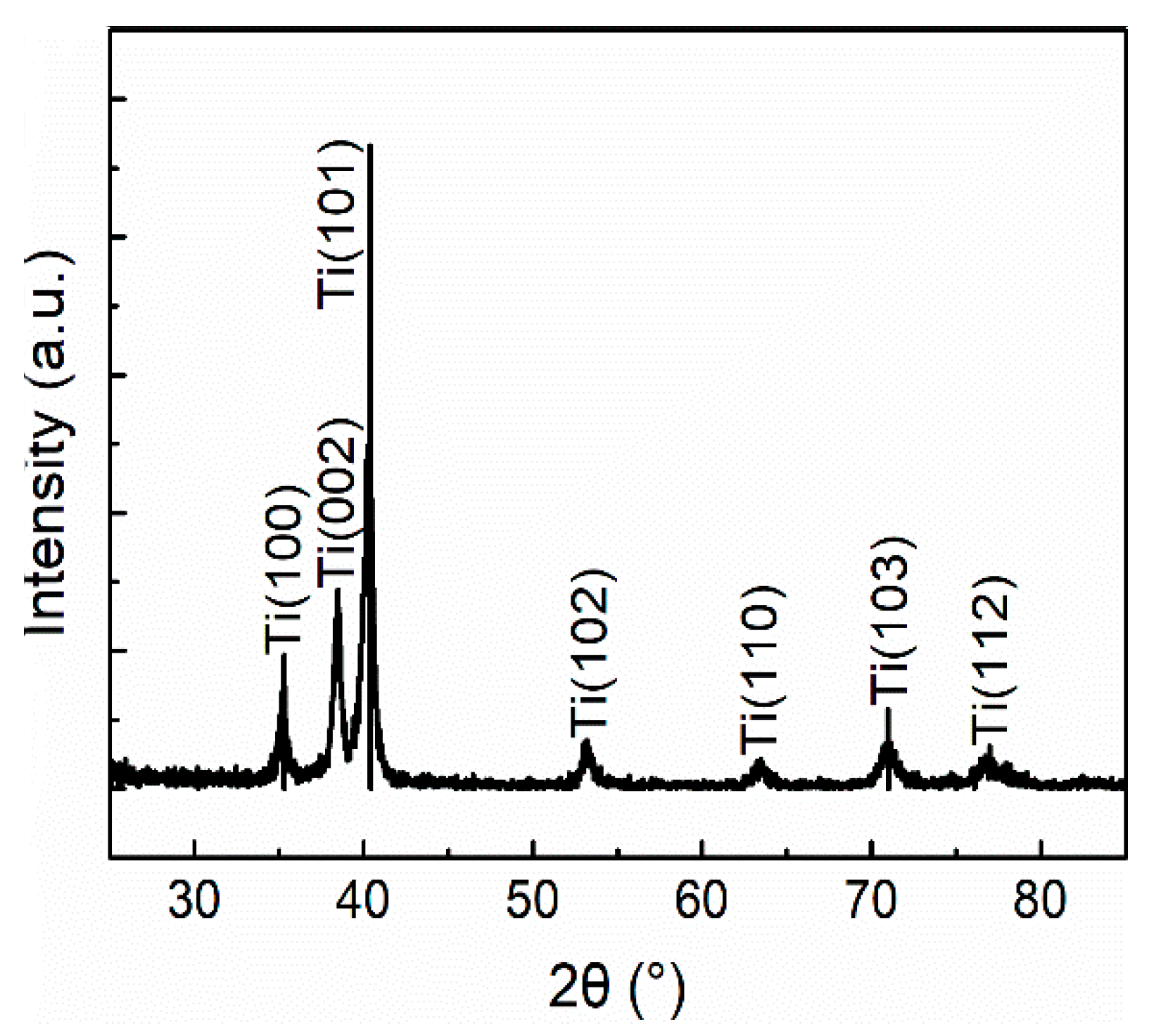
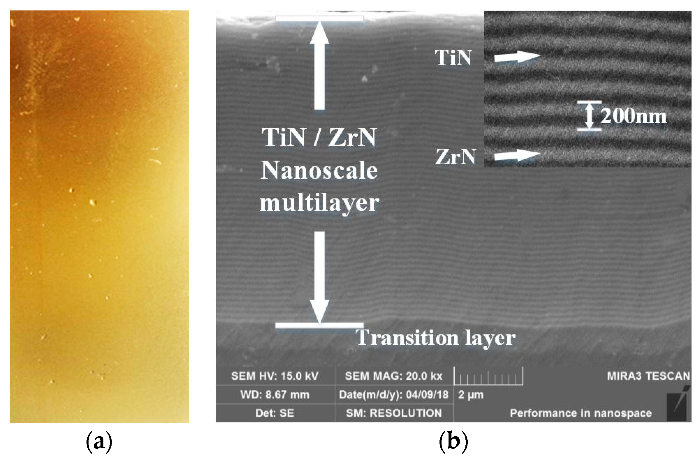
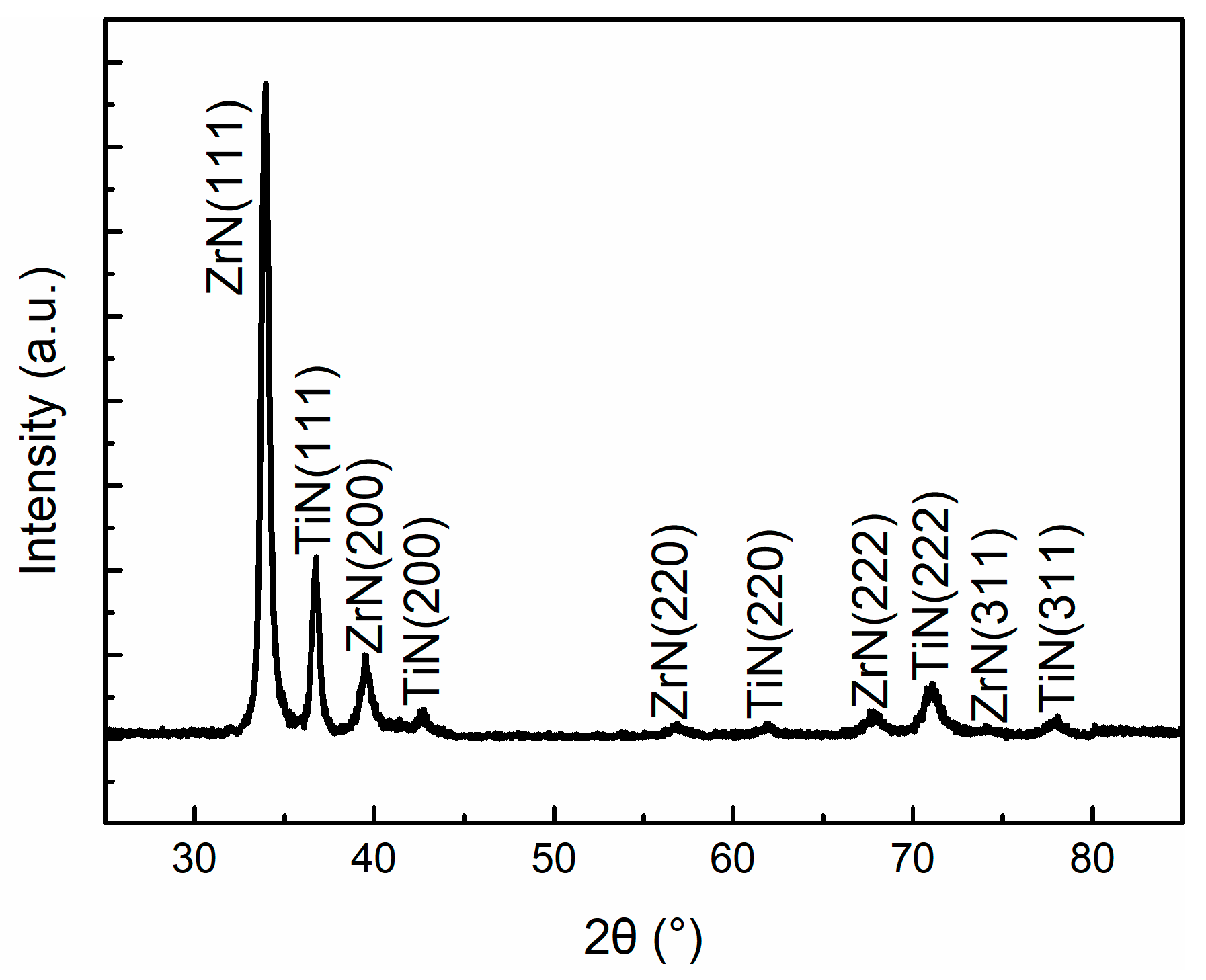
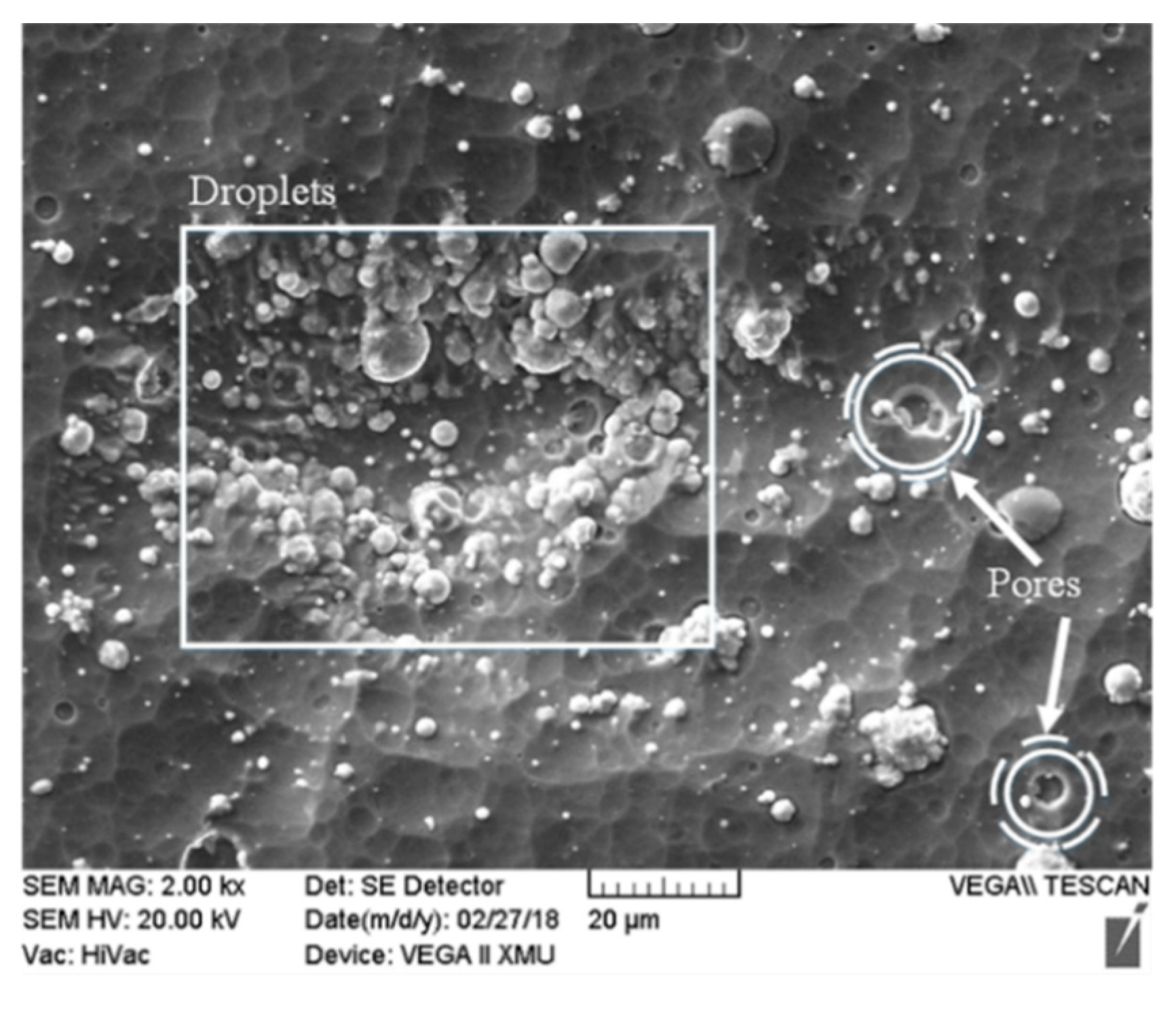
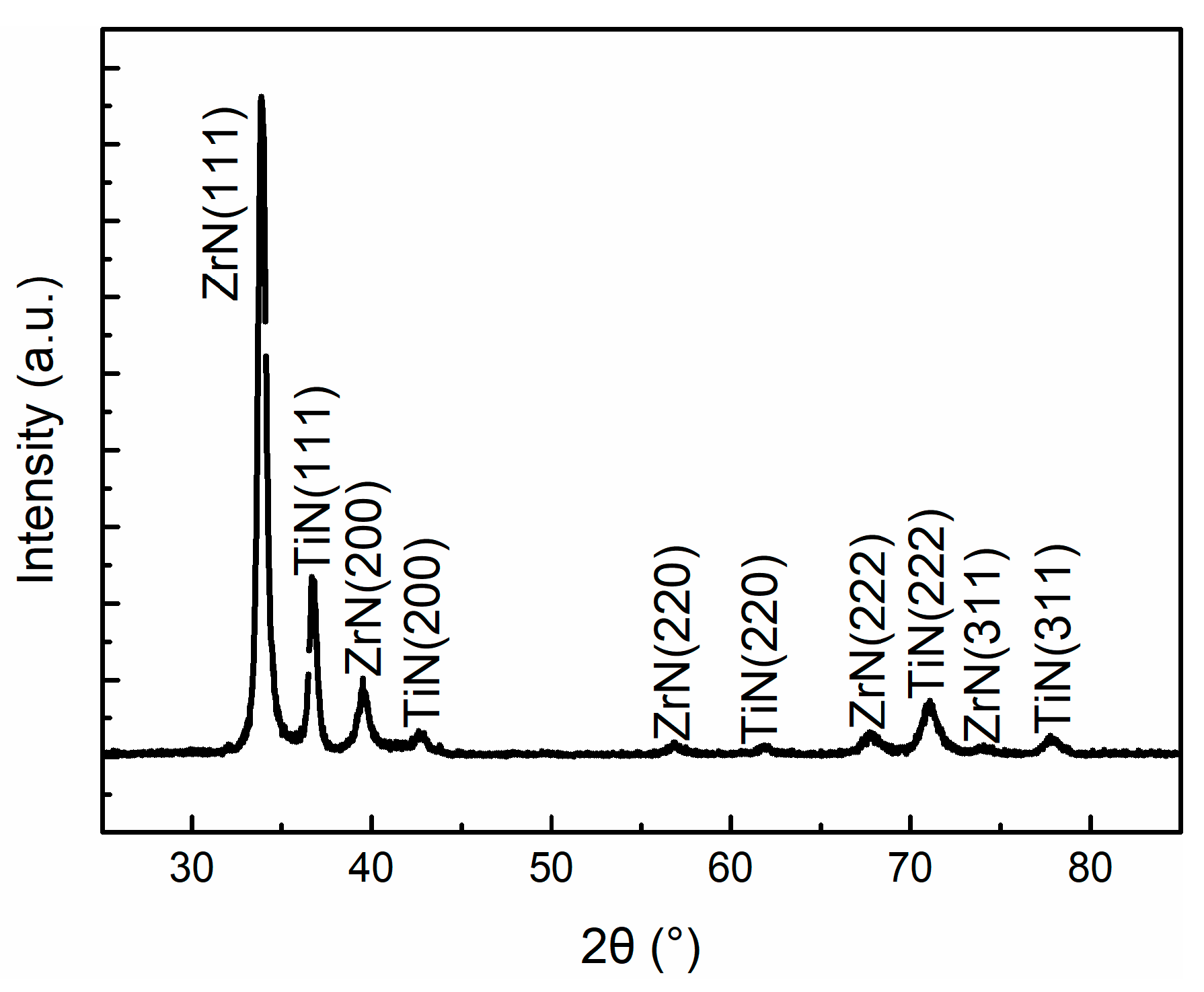
3.1. Coating Characterization

Figure 3 illustrates the surface and cross-sectional morphologies of TiN/ZrN nanolaminate coatings. The coating possessed the typical golden appearance of TiN and ZrN. As shown in Figure 3b, the coating had a distinct multilayer structure and the layers were also visible. The dark and bright layers correspond to TiN and ZrN layers, respectively. The total thickness of the coating was about 10 μm. The top layer of the coating was TiN. Single TiN or ZrN layer was coated with the same thickness (100 nm). To enhance the substrate/coating bonding, a buffer layer (Ti), with a thickness of 1 μm, was deposited on the substrate.
According to the X-ray diffraction investigations (Figure 4), both the TiN and ZrN phases were face-centered cubic structures. The preferred growth orientations of the phases were [111] direction, consistent with the design.

3.2. Salt Spray Corrosion

The salt spray test was used to simulate the corrosion behavior of the samples in the marine atmosphere. The surface morphology and micrograph of Ti-6Al-4V alloy exposed to a salt spray environment for 576 h are shown in Figure 5a and Figure 6, respectively. The metallic luster was still maintained on the surface of the sample. Small pits with the maximum diameter about 15 μm were also observed, which indicates that the pitting corrosion was the damage mode of Ti-6Al-4V alloy under the salt spray environment.
XRD pattern of Ti-6Al-4V alloy after 576 h exposure to salt spray environment is presented in Figure 7. The XRD studies showed that the corrosion products were Ti2O and TiO2; Ti, Ti2O and TiO2 phases were observed.
Ti-6Al-4V alloy is corrosion-resistant in highly corrosive environments. It was reported that the titanium alloy could form a protective oxide scale under different environmental conditions, such as simulated chemical, marine and industrial environments below 50 °C. The degradation mode is uniform corrosion, pitting and crevice corrosion [12].
The surface morphology and micrograph of the coating exposed to a salt spray environment for 576 h are shown in Figure 5b and Figure 8, respectively. The coating maintained the original golden appearance. There were no obvious changes to the surface morphology. Furthermore, defects such as droplets and pores were maintained. Based on the analysis of SEM images, the coating was not susceptible to pitting corrosion.
XRD pattern of the coating after 576 h exposure to salt spray environment is presented in Figure 9. According to X-ray diffraction, TiN and ZrN phases with the preferred [111] orientation were observed, which is the same as in Figure 4.
The result shows that TiN/ZrN nanolaminate coating deposited on the surface of Ti-6Al-4V was stable in the salt spray condition.
In salt spray condition, corrosion protection by the alternating structured of TiN/ZrN provided improved corrosion resistance for the substrate. TiN does not react significantly with the environment, and can be regarded as a barrier effect of the inert coating to prevent the contact of the aggressive ions with the substrate. In this case, the defects in the coating can provide a diffusion channel for the aggressive ions, leading to the contact of the ions with the substrate, and causing the corrosion of the substrate, eventually. Therefore, TiN layer is highly sensitive to defects [13,14] and the coating quality is then the controlling parameter for corrosion protection. In contrast, nitrogen in ZrN can be replaced by oxygen to form ZrO2, or oxygen is present in ZrN as a Zr-O-N layer [11], thereby forming a protective layer to prevent further corrosion of the sample by the environment [15,16]. Therefore, ZrN is less sensitive to defects, which makes up for the deficiency of TiN.
The existence of TiN layers prevented the contact of most aggressive ions from the substrate, thus delaying the corrosion process. However, the reaction between substrate and environment may occur, considering the penetration of the electrolyte through the defects of TiN. In the TiN/ZrN nanolaminate coating, on the one hand, defects such as droplets, pores or crevices might be neutralized or “masked” by the multilayer structure, making the corrosion agents’ path longer or blocked [17]; on the other hand, aggressive ions lost their transport path because of the insensitivity to defects of ZrN layers. This corrosion process is shown schematically in Figure 10.

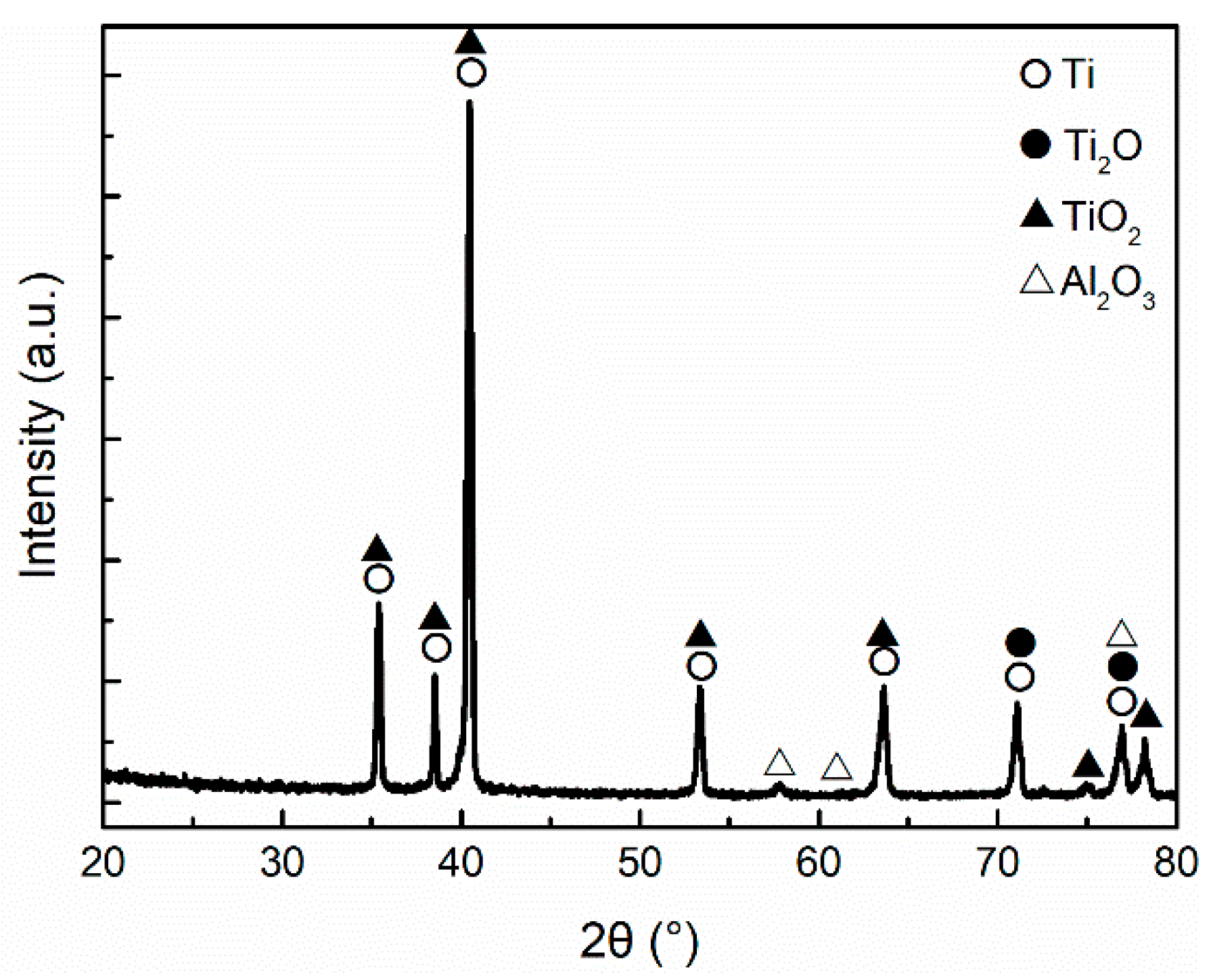
3.3. Low Temperature Hot Corrosion

The test was used to simulate the corrosion behavior of materials in high temperature corrosive environments during engine operation [18]. The weight of the samples was measured at the end of each cycle and the mass loss was calculated. Figure 11 shows the weight loss of Ti-6Al-4V as a function of time, showing several stages. Planes were indicated in all three stages. Initially, the weight of Ti-6Al-4V was increased obviously (0.05 mg·cm−2) and then rapid weight decrease occurred after the sample was maintained under corrosion condition for 24 and 64 h, and reached 0.06 mg·cm−2 at the end of the test. At the first stage of Ti-6Al-4V sample in Figure 11, the increased weight was a result of the oxidation reactions. Although the peeling of oxidation film occurred, the exposure time was not long enough to cause an extensive damage of the film. The area of peeling was much less than oxidation area, thus the weight variation of sample was dominated by oxidation.
As for TiN/ZrN nanolaminate coating, it was observed that the weight remained invariable (weight increase 0.01 mg·cm−2) in the first 20 h and then decreased approximately linearly with time, with a slope of 0.003 mg·cm−2·h−1), and reached to 0.24 mg·cm−2 at the end of the test.
Figure 12 is the surface morphologies of the Ti-6Al-4V alloy and the TiN/ZrN nanolaminate coating after hot corrosion for 88 h. The Ti-6Al-4V alloy lost its metallic luster, indicating an oxidation behavior of the surface. The TiN/ZrN coating lost its golden luster, and the surface was darkened.
XRD pattern of Ti-6Al-4V titanium alloy after 4 h exposure to hot corrosion environment is presented in Figure 13. Ti2O, TiO2 and Na2SO4 were the only phases found in the spectrum. The appearance of Na2SO4 on the surface was probably due to the remaining salt film. Oxidation products (Ti2O and TiO2) occurring on the surface confirms the extensive oxidation reaction during the initial stage.
Figure 14 displays the SEM image of the sample. The pattern was divided into three regions. Region A showed oxide scale formed on the surface with an even appearance. Its chemical composition was Ti-7.35Al-1.97V-35.79O (wt.%). Region B showed fresh material exposed after the oxide film was peeled off. Its chemical composition was Ti-10.64Al-4.36V (wt.%). Region C showed oxidation products containing more oxygen than Region A. Its chemical composition was Ti-3.59Al-1.93V-0.20Na-0.05S-64.02O-0.08Cl (wt.%). According to the XRD pattern in Figure 13, Region C contains phases from salt film, as it was the only region containing Cl and S. Al was enriched at all three regions, due to the segregation during oxidation reaction.
It is reported that, during the oxidation process at high temperature, oxidation products of less noble metal would form an outer oxide layer, because of the outward diffusion of less noble metal [19,20]. Since Al is more active than Ti, it was enriched at all three regions. Generally, the oxidation film formed on the surface of titanium alloy has a layered structure with weak bonding between interlayer. The peeling of oxidation film leads to the exposure of the fresh material, thus forming Region B.
Figure 15 is the XRD diffractogram of Ti-6Al-4V alloy after hot corrosion for 88 h, in which Al2O3 phase appeared, indicating that the Al segregation and alloy oxidation were aggravating.
Figure 16 displays the SEM image of Ti-6Al-4V titanium alloy after 88 h exposure to hot corrosion environment. The pattern was divided into two regions. Region A, whose chemical composition was Ti-6.68Al-0.74V-40.39O (wt.%), possessed a relatively flat appearance. Comparing to the initial stage, the Al and O contents were increased, confirming that the segregation and oxidation phenomenon were more obvious with time. Region B, whose chemical composition was Ti-2.27Al-1.38V-3.49Na-0.24S-0.24Cl-65.59O (wt.%), contained a few cracks. The zone evolved from the Region C in Figure 9. Oxidation produces vulnerable areas on the surface, which led to the initiation propagation of cracks under the effect of cyclic thermal stress. The corrosion appearance was thus formed.
This stage corresponded to the third part of Ti-6Al-4V sample in Figure 11. Platforms of the curve were associated with the rapid rate of oxidation and the periodic peeling of the film. Oxygen content was not changed significantly with increasing corrosion time (contrast Region A in Figure 16 with Region A in Figure 14, Region B in Figure 16 and Region C in Figure 14), indicating that the oxidation of the material was saturated at this time. Therefore, the weight variation of sample was dominated by the peeling of oxidation film under the effect of cyclic thermal stress.
XRD pattern of TiN/ZrN nanolaminate coating after 4 h exposure to hot corrosion environment is presented in Figure 17. It was similar to the original pattern shown in Figure 4. The coating exhibited better oxidation resistance than substrate. Figure 18 displays the SEM image corresponding to the sample. There were some spots on the surface of the coating, whose chemical composition was Ti-21.12Zr-14.30N-35.46O-0.45Na (wt.%). This should be oxidation product of the coating. The chemical composition of other areas was Ti-16.10Zr-59.51N (wt.%), without the phenomenon of oxidation.
This stage corresponded to the first 20 h of the coating sample in Figure 11. There were only a few areas where oxides appeared, distributing randomly. Its adsorption of oxygen was much smaller than that of Ti-6Al-4V, and no obvious transformation of component or morphology appeared. Therefore, the weight increased slightly at this stage.
According to Figure 19, the oxidation of the coating was not obvious. XRD diffractogram of TiN/ZrN coating after hot corrosion for 88 h was also similar to before the test.
Figure 20 displays the SEM image of TiN/ZrN nanolaminate coating after 88 h exposure to hot corrosion environment. Region A, whose chemical composition is Ti-13.68Zr-69.32O (wt.%), was the central zone. The N in the TiN can be completely replaced by O when the ambient temperature is higher than 600 °C [21]. Region A was the corrosion product of the metal droplets produced during the preparation of the coating. In general, the ratio of the volume of the metal oxide film and that of the metal to be consumed, which are formed by the oxidation of Ti and Zr to TiO2 and ZrO2, is 1.95 and 1.51, respectively. The droplets expanded due to oxidation, and the coating was thus squeezed and peeled off.
Region B, whose chemical composition was Ti-14.46Zr-36.71N-29.63O (wt.%), contained concentric rings. Region C, whose chemical composition was Ti-16.18Zr-45.95N-15.31O (wt.%), was the undamaged area of the specimen. These regions were formed with the participation of the oxidation reaction. It is shown that TiN/ZrN nanolaminate coating tended to be oxidized under the condition. Reasons for the different results between XRD and EDS analysis are explained below.
It corresponded to the stage where the sample weight decreased linearly with time. When the TiN/ZrN coating was oxidized, bending of layers, stratification with separation and loss of strength occurred, because of the volume fraction changes of TiN and ZrN layers [22]. The droplets oxidized and expanded with time, and the coating nearby was squeezed. Meanwhile, these areas were vulnerable points in the coating, which led to peeling of the coating. The peeling was continuous as the droplets expanded and the coating oxidized constantly, leading to the linear weight decrease after the initial slight increase.
The oxidation of ZrN can proceed at room temperature [23], ZrN possesses a good oxidation resistance due to the stable oxidation scale. However, the thickness of the scale increases with exposure time and temperature of the environment, leading to phase transformation of TiO2. This provides fast diffusion paths of oxygen and hence decreases the oxidation resistance [24]. TiN can also be oxidized at 300 °C, it has been reported that the process is controlled by the temperature dependence of the oxygen diffusion, which is different from ZrN and easier to be oxidized [25].
The structure of TiN/ZrN multilayer coating seems to improve the oxidation resistance of TiN and ZrN coating. The free energy of oxide formation of TiN is higher than that of ZrN, which means ZrN layers are oxidized more easily than TiN layers. Thus, the oxidation process of the next TiN layer would be prohibited, unless ZrN layer is oxidized completely [26]. The mechanism of layered oxidation relieved thermal stress and avoided the peeling caused by growth stress during the oxidation. Meanwhile, [111] texture in the surface layers was proved to play a significant role in preventing the inner layers from oxidation, which improved the oxidation resistance of TiN/ZrN multilayer coatings [27]. According to Figure 20, it is obvious that the coating peeled layer by layer, indicating that its oxidation should also be layered.
The temperature and exposure time can dominate the influence depth of oxygen. Since the XRD analysis has a certain testing depth, it is possible that the layered oxidation on the coating surface cannot be captured when the corrosion conditions are not aggressive enough, causing the difference between the XRD and EDS analysis.
It is obvious that, even though the oxidation of TiN/ZrN coating may lead to bending of layers, stratification with separation and degradation of strength, it was not the direct cause resulting in peeling of the coating. The oxidation weakened the coating, and then droplets expanded due to oxidation. The coating was thus squeezed and peeled off, decreased the sample weight obviously. Figure 21a–c presents schematic diagrams of the corrosion process of TiN/ZrN coating in hot corrosion environment.
According to the curve in Figure 11, although the apparent material loss of Ti-6Al-4V alloy was significantly less than that of TiN/ZrN nanolaminate coating, the coating could still protect substrate against the corrosion in certain condition.
The surface of Ti-6Al-4V titanium alloy was extensively oxidized at the beginning of corrosion, resulting in the sample weight increase. However, the existence of oxide film could not prevent the further oxidation of the sample. Due to the damage process of oxidation on the surface, oxide film peeling, and oxidation of fresh material, the weight of the sample changed in stages and the material gradually oxidized and peeled off.
As for TiN/ZrN nanolaminate coating, the peeling of the coating was result of the oxidation of the coating and the squeezing caused by the oxidation and expanding of droplets, and the mode was mechanical. Meanwhile, the corrosion process occurred only in the coating, and the substrate was not directly exposed to the environment, which prevented the corrosion and oxidation of the substrate. The TiN/ZrN nanolaminate coating may not be applicable in erosion–oxidation conditions, in which the oxidized layers are likely to be destroyed. It is reasonable to improve the hot corrosion resistance and reduce the peeling of the coating by improving the quality of the coating and reducing the number of droplets.

4. Conclusions

Multi-arc ion plating method was used to deposit [Tin/ZrN]100 nanolaminate coating on a Ti-6Al-4V alloy. The coating thickness was about 10 μm. To study the corrosion resistance of the coating under the service conditions of the compressor, corrosion behavior of the coating in spray salt and low temperature hot conditions was evaluated. The results can be summarized as follows:
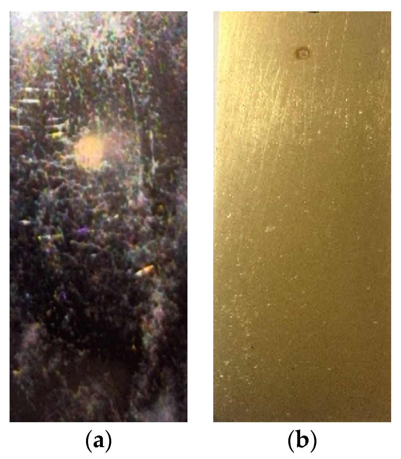
  • The coating exhibited good corrosion resistance in aggressive conditions. After 576 h spray salt corrosion test, the composition and appearance of coating were not significantly changed. After 88 h low temperature hot corrosion test, the coating was oxidized and the oxidized layers might protect substrate against the corrosion and oxidation.
  • The oxidation and expansion of droplets led to squeezing and peeling of the coating in low temperature hot condition. The low temperature hot corrosion resistance of TiN/ZrN nanolaminate coating could be effectively improved, by improving the quality of the coating and reducing the number of droplets.

Author Contributions

Writing—Original Draft Preparation and Formal Analysis, M.G.; Funding Acquisition, G.H. and Z.S; Conceptualization and Writing-Review & Editing, G.H.; Investigation, Z.S. and J.C.; Resources, Z.Y. and Y.L.

Funding

This research was funded by the National Natural Science Foundation of China (No. 51405506) and Shaanxi Natural Science Foundation (No. 2017JM5071).

Acknowledgments

Thanks to Songsheng Lin for giving help on coatings deposition.

Conflicts of Interest

The authors declare no conflict of interest.

References

  1. Huang, Y.; Xiao, G.; Zhao, H.; Zou, L.; Zhao, L.; Liu, Y.; Dai, W. Residual stress of belt polishing for the micro-stiffener surface on the titanium alloys. Procedia CIRP 2018, 71, 11–15. [Google Scholar] [CrossRef]
  2. Evstifeev, A.; Kazarinov, N.; Petrov, Y.; Witek, L.; Bednarz, A. Experimental and theoretical analysis of solid particle erosion of a steel compressor blade based on incubation time concept. Eng. Fail. Anal. 2018, 87, 15–21. [Google Scholar] [CrossRef]
  3. Pedram, O.; Poursaeidi, E. Total life estimation of a compressor blade with corrosion pitting, SCC and fatigue cracking. J. Fail. Anal. Prev. 2018, 4, 423–434. [Google Scholar] [CrossRef]
  4. Cai, F.; Gao, F.; Pant, S.; Huang, X.; Yang, Q. Solid particle erosion behaviors of carbon-fiber epoxy composite and pure titanium. J. Mater. Eng. Perform. 2016, 25, 290–296. [Google Scholar] [CrossRef]
  5. Urbahs, A.; Rudzitis, J.; Savkovs, K.; Urbaha, M.; Boiko, I.; Leitans, A.; Lungevics, J. Titanium compound erosion-resistant nano-coatings. Key Eng. Mater. 2016, 674, 283–288. [Google Scholar] [CrossRef]
  6. Mednikov, A.F.; Kachalin, G.V.; Ryzhenkov, A.V.; Tkhabisimov, A.B. An investigation of ion-plasma coatings solid particle erosion resistance at high-speed impact of gas-abrasive flow. In Proceedings of the 2nd International Conference on High Performance and Optimum Design of Structures and Materials (HPSM 2016), Siena, Italy, 19–21 September 2016; pp. 487–497. [Google Scholar] [CrossRef]
  7. Bondar, O. Dependence of mechanical and tribotechnical properties of multilayered TiN/ZrN coatings on deposition. Przegląd Elektrotechniczny 2015, 1, 233–236. [Google Scholar] [CrossRef]
  8. Muboyadzhyan, S.A.; Aleksandrov, D.A.; Gorlov, D.S. Ion-plasma erosion-resistant nanocoatings based on metal carbides and nitrides. Rus. Metall. 2010, 9, 790–799. [Google Scholar] [CrossRef]
  9. Chou, W.J.; Yu, G.P.; Huang, J.H. Corrosion behavior of TiN-coated 304 stainless steel. Corros. Sci. 2001, 43, 2023–2035. [Google Scholar] [CrossRef]
  10. Chen, B.F.; Pan, W.L.; Yu, G.P.; Hwang, J.; Huang, J.H. On the corrosion behavior of TiN-coated AISI D2 steel. Surf. Coat. Technol. 1999, 111, 16–21. [Google Scholar] [CrossRef]
  11. Brown, R.; Alias, M.N.; Fontana, R. Effect of composition and thickness on corrosion behavior of TiN and ZrN thin films. Surf. Coat. Technol. 1993, 62, 467–473. [Google Scholar] [CrossRef]
  12. Gurrappa, I. Characterization of titanium alloy Ti-6Al-4V for chemical, marine and industrial applications. Mater. Charact. 2003, 51, 131–139. [Google Scholar] [CrossRef]
  13. Vega, J.; Scheerer, H.; Andersohn, G.; Oechsner, M. Experimental studies of the effect of Ti interlayers on the corrosion resistance of TiN PVD coatings by using electrochemical methods. Corros. Sci. 2018, 133, 240–250. [Google Scholar] [CrossRef]
  14. Ghasemia, S.; Shanaghia, A.; Chub, P.K. Corrosion behavior of reactive sputtered Ti/TiN nanostructured coating and effects of intermediate titanium layer on self-healing properties. Surf. Coat. Technol. 2017, 326, 156–164. [Google Scholar] [CrossRef]
  15. Huang, J.H.; Tsai, Z.E.; Yu, G.P. Mechanical properties and corrosion resistance of nanocrystalline ZrNxOy coatings on AISI 304 stainless steel by ion plating. Surf. Coat. Technol. 2008, 202, 4992–5000. [Google Scholar] [CrossRef]
  16. Lei, Z.; Zhang, Q.; Zhu, X.; Ma, D.; Ma, F.; Song, Z.; Fu, Y. Corrosion performance of ZrN/ZrO2, multilayer coatings deposited on 304 stainless steel using multi-arc ion plating. Appl. Surf. Sci. 2017, 431, 170–176. [Google Scholar] [CrossRef]
  17. Dobrzański, L.A.; Lukaszkowicz, K.; Zarychta, A.; Cunha, L. Corrosion resistance of multilayer coatings deposited by PVD techniques onto the brass substrate. J. Mater. Process. Technol. 2006, 15, 816–821. [Google Scholar] [CrossRef]
  18. Peters, M.; Kumpfert, J.; Ward, C.H.; Leyens, C. Titanium alloys for aerospace applications. Adv. Eng. Mater. 2003, 5, 419–427. [Google Scholar] [CrossRef]
  19. Wagner, C. Theoretical analysis of the diffusion processes determining the oxidation rate of alloys. J. Electrochem. Soc. 1952, 99, 369–380. [Google Scholar] [CrossRef]
  20. Wagner, C. Oxidation of alloys involving noble metals. J. Electrochem. Soc. 1956, 103, 571–580. [Google Scholar] [CrossRef]
  21. Milošev, I.; Strehblow, H.H.; Navinšek, B. XPS in the study of high-temperature oxidation of CrN and TiN hard coatings. Surf. Coat. Technol. 1995, 74, 897–902. [Google Scholar] [CrossRef]
  22. Pogrebnjak, A.D.; Ivasishin, O.M.; Beresnev, V.M. Arc-evaporated nanoscale multilayer nitride-based coatings for protection against wear, corrosion, and oxidation. Usp. Fiz. Met. 2016, 17, 1–28. [Google Scholar] [CrossRef]
  23. Muneshwar, T.; Cadien, K. Comparing XPS on bare and capped ZrN films grown by plasma enhanced ALD: Effect of ambient oxidation. Appl. Surf. Sci. 2018, 435, 367–376. [Google Scholar] [CrossRef]
  24. Qi, Z.B.; Wu, Z.T.; Liang, H.F.; Zhang, D.F.; Wang, J.H.; Wang, Z.C. In situ and ex situ studies of microstructure evolution during high-temperature oxidation of ZrN hard coating. Scr. Mater. 2015, 97, 9–12. [Google Scholar] [CrossRef]
  25. Soriano, L.; Abbate, M.; Fuggle, J.C.; Prieto, P.; Jiménez, C.; Sanz, J.M.; Galán, L. Thermal oxidation of TiN studied by means of soft X-ray absorption spectroscopy. J. Vac. Sci. Technol. A 1993, 11, 47–51. [Google Scholar] [CrossRef]
  26. Xu, X.M.; Wang, J.; Zhang, Q.Y. Oxidation behavior of TiN/ZrN multilayers annealed in air. Thin Solid Films 2008, 516, 1025–1028. [Google Scholar] [CrossRef]
  27. Pogrebnjak, A.; Ivashchenko, V.; Bondar, O.; Beresnev, V.; Sobol, O.; Załęski, K.; Jurga, E.; Coy, E.; Konarski, P.; Postolnyi, B. Multilayered vacuum-arc nanocomposite TiN/ZrN coatings before and after annealing: Structure, properties, first-principles calculations. Mater. Charact. 2017, 134, 55–63. [Google Scholar] [CrossRef] [Green Version]
Figure 1. XRD diffractogram of TiN /ZrN coatings.
Coatings 08 00400 g001
Figure 2. Schematic image of the deposition chamber.
Coatings 08 00400 g002
Figure 3. The morphology of (a) surface of the coating and (b) cross section.
Coatings 08 00400 g003
Figure 4. XRD diffractogram of TiN /ZrN coatings.
Coatings 08 00400 g004
Figure 5. The morphology of (a) Ti-6Al-4V titanium alloy, and (b) TiN/ZrN coating after salt spray corrosion.
Coatings 08 00400 g005
Figure 6. SEM image of Ti-6Al-4V titanium alloy after salt spray corrosion for 576 h.
Coatings 08 00400 g006
Figure 7. XRD diffractogram of Ti-6Al-4V titanium alloy after salt spray corrosion for 576 h.
Coatings 08 00400 g007
Figure 8. SEM image of TiN/ZrN coating after salt spray corrosion for 576 h.
Coatings 08 00400 g008
Figure 9. XRD diffractogram of TiN/ZrN coating after salt spray corrosion for 576 h.
Coatings 08 00400 g009
Figure 10. Schematic diagram of the corrosion process of TiN/ZrN coating in salt spray environment.
Coatings 08 00400 g010
Figure 11. Comparison of the mass loss trend for Ti-6Al-4V substrate and TiN/ZrN coating.
Coatings 08 00400 g011
Figure 12. The hot corrosion surface after 88 h of (a) Ti-6Al-4V substrate and (b) TiN/ZrN coating.
Coatings 08 00400 g012
Figure 13. XRD diffractogram of Ti-6Al-4V alloy after hot corrosion for 4 h.
Coatings 08 00400 g013
Figure 14. SEM morphology of Ti-6Al-4V titanium alloy after hot corrosion for 4 h.
Coatings 08 00400 g014
Figure 15. XRD diffractogram of Ti-6Al-4V alloy after hot corrosion for 88 h.
Coatings 08 00400 g015
Figure 16. SEM morphology of Ti-6Al-4V titanium alloy after hot corrosion for 88 h.
Coatings 08 00400 g016
Figure 17. XRD diffractogram of TiN/ZrN coating after hot corrosion for 4 h.
Coatings 08 00400 g017
Figure 18. SEM image of TiN/ZrN coating after hot corrosion for 4 h.
Coatings 08 00400 g018
Figure 19. XRD diffractogram of TiN/ZrN coating after hot corrosion for 88 h.
Coatings 08 00400 g019
Figure 20. SEM image of TiN/ZrN coating after hot corrosion for 88 h.
Coatings 08 00400 g020
Figure 21. Schematic diagram of the corrosion process of TiN/ZrN coating in hot corrosion environment. (a) Oxidation of the surface; (b) Layered oxidation and crack propagation; (c) Squeezed and peeled off.
Coatings 08 00400 g021
Table 1. Chemical composition of Ti-6Al-4V titanium alloy (wt.%).
FeVAlCONHTi
0.104.005.700.020.05<0.01<0.001Bal.
Table 2. Processing Parameters.
N2 Pressure (Pa)Bias Voltage (V)Arc Current (A)Coating ThicknessLayer
1.0−10010010 μm100

