Article

Effect of Self-Generated Transfer Layer on the Tribological Properties of PTFE Composites Sliding against Steel

Institute of Tribology, Hefei University of Technology, Hefei 230009, China
*
Author to whom correspondence should be addressed.
Coatings 2018, 8(11), 399; https://doi.org/10.3390/coatings8110399
Submission received: 28 September 2018 / Revised: 29 October 2018 / Accepted: 10 November 2018 / Published: 13 November 2018

Abstract

:
Coatings are normally employed to meet some functional requirements. There is a kind of self-generated coating during use, such as the transfer layer during sliding, which may greatly affect the tribological behavior. Although the transfer layer has aroused much attention recently, the formation of the transfer layer closely depends on the service conditions, which need to be further studied. In this paper, the effects of sliding speed, normal load, and duration of wear test on the transfer layer thickness during friction of Ni/PTFE (Polytetrafluoroethylene) composites were experimentally investigated. The formation mechanism of transfer layer and the relationships between tribological properties and transfer layer thickness were analyzed in detail. It was found that the transfer layer thickness increased with increases of sliding speed and normal load; and after a period of wear test, the transfer layer thickness remained stable. The transfer layer thickness correlates linearly with the friction coefficient and wear volume of the PTFE composites. With the increase of the transfer layer thickness, the friction coefficient decreased, while the wear volume increased, which means that a uniform, thin, and stable transfer layer is beneficial for the reduction of friction and wear of the polymeric composites.

1. Introduction

Various coatings have been widely used in many applications, such as in protection from corrosion [1,2], in anti-friction and anti-wear [3,4], in wave or light absorbing [5,6], or in other fields. According to different service requirements, there are many preparation methods for these coatings, such as physical vapor deposition (PVD), chemical vapor deposition (CVD), plating, cladding, spraying and so on [7,8,9]. There are also a class of protective coatings that are generated automatically during use, which can play the role of self-protection, self-repairing, or self-improvement. For example, during sliding, two kinds of coatings can be formed on the frictional surface: One is a chemical reaction coating and the other is a transfer layer. The chemical reaction coating is the oxide coating or other compound coating formed on the frictional surface during sliding, which can repair and protect the frictional surface and reduce friction and wear [10,11,12,13]. The transfer layer is due to the transfer of materials onto the counterface of the frictional couple to form a layer of adhesive coating. The role of the transfer layer is to change the contact state of the frictional surfaces, to protect the surface and reduce friction [14,15,16,17,18,19]. For the metal-polymer sliding system, a polymer transfer layer will be formed spontaneously on the surface of the metal part during sliding, which will transform the friction contact of metal-polymer into polymer-polymer, thus reducing friction and wear. Although it has been proved that the properties of the transfer layer will greatly affect the tribological performance of the friction system [20,21,22,23], there are still many aspects to be further studied, such as the relationship between the transfer layer thickness and the sliding conditions, the correlation between the transfer layer thickness and the tribological properties, etc., which have been rarely reported. Therefore, this work focused on the effects of frictional conditions on transfer layer thickness of PTFE composites, and analyzed the relationship between the transfer layer thickness and the tribological properties, hoping to achieve the optimization of friction properties by controlling the formation scale of the self-generated transfer layer.

2. Materials and Methods

2.1. Materials

Polytetrafluoroethylene (PTFE, Shanghai 3F New Materials Technology Co. Ltd., Shanghai, China), white powders with an average particle size of about 30 μm, was selected as a matrix for the composites. The filler was nickel powder (Ni, average diameter of about 64 μm). The pin samples (Ø10 mm × 30 mm) of PTFE composites (with 15 wt % Ni) were prepared by mixing, pressing and sintering. The counterface samples used in this study were steel 45 discs (Ø50 mm × 4 mm). In order to mix the components evenly, a high-speed mixer (YF2-2, Ruian YongLi Pharmaceutical Machinery Co. Ltd., Ruian, China) was adopted. The powder mixture was compacted in a cylindrical mold at 55 MPa of pressure and then removed from the mold and heated in a nitrogen protective sintering furnace (JHN-1, Hefei University of Technology, Hefei, China) using a ramp to 205 °C in 100 min (hold 30 min), a ramp to 360 °C in 100 min (hold 180 min), a ramp to 275 °C in 60 min (hold 60 min), and a ramp to 180 °C in 100 min. Steel 45 is a low carbon steel with ~0.45 wt pct C, the hardness is about HRC28, and the surface roughness Ra is about 0.1 μm.

2.2. Methods

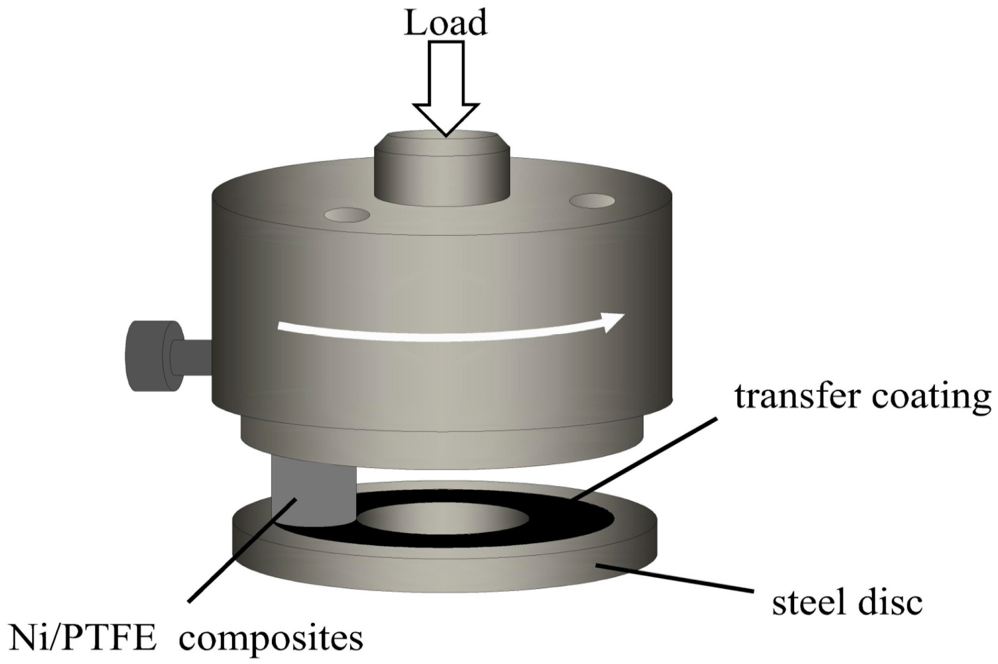
2.2.1. Friction Experiments

The friction and wear tests were carried out on a multifunctional tribometer, designed by the Hefei University of Technology. The friction coefficient was measured by a shaft torque meter. The pin-on-disc tests were conducted under dry sliding and room temperature (as shown in Figure 1). The wear loss of each sample was measured by the electronic balance (FA2104B, accuracy is 0.1 mg). Each test lasted 35 min and was repeated at least three times.

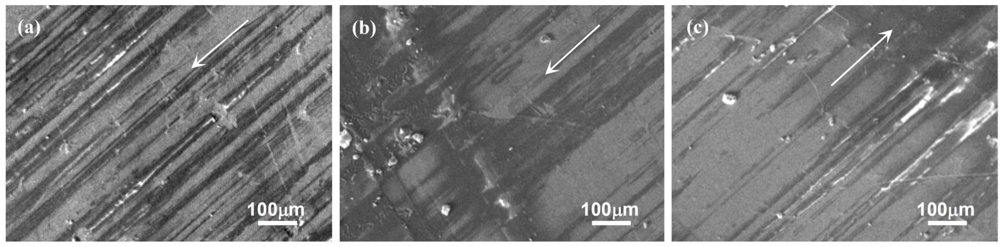
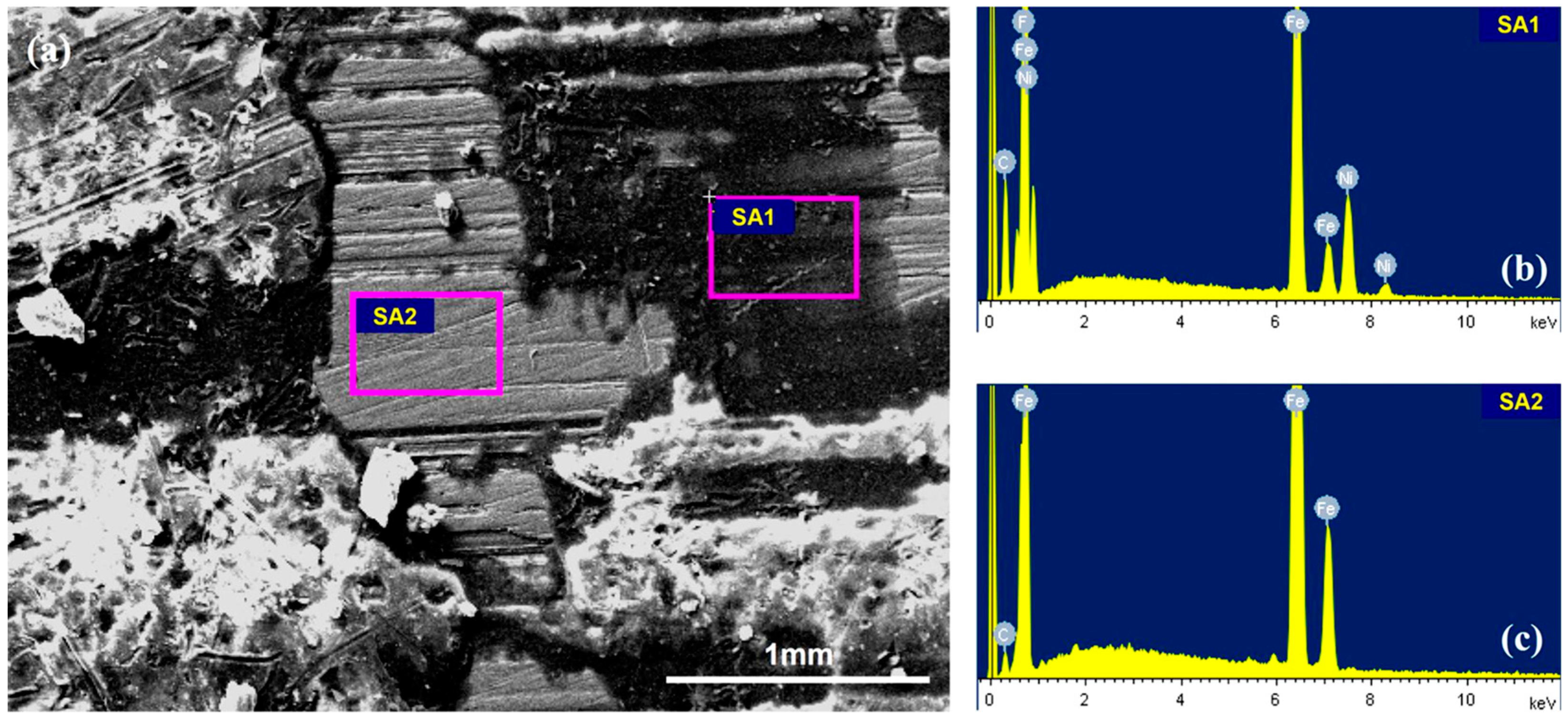
2.2.2. Observation of the Worn Surfaces

The transfer layer was observed and analyzed by 3D laser scanning microscope (Keyence, VK-X100K, Osaka, Japan, with an accuracy of 0.012 μm) and scanning electron microscope (JEOL, JSM-6360, Tokyo, Japan), and EDS (INCA, version with Si(Li) detector).

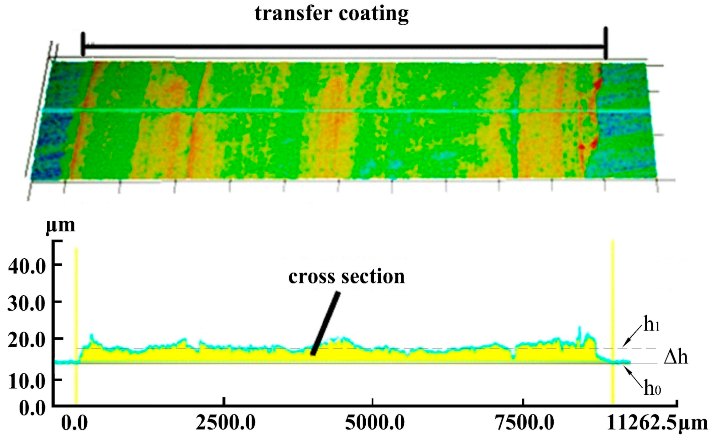
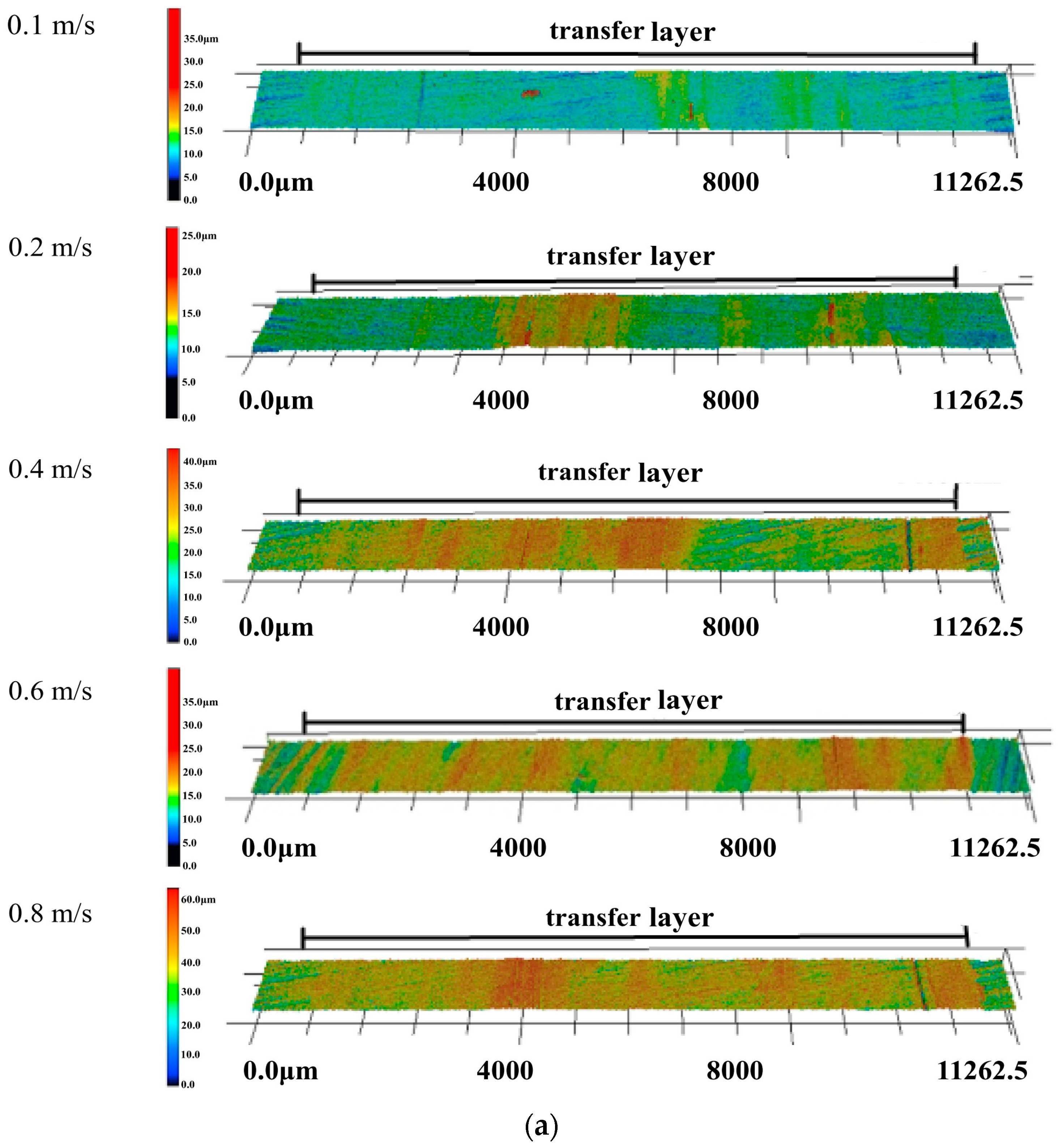
2.2.3. Measurement of the Transfer Layer Thickness

The above mentioned Keyence 3D laser scanning microscope was employed to measure the thickness of the transfer layer at four different positions evenly distributed along the circular wear track on the counterface. The measurement was repeated at least three times on the same position in order to reduce the random errors and ensure the accuracy and reproducibility of the test results. The transfer layer was determined by the difference of h1 (average profile height of transfer layer on sliding surface) and h0 (average profile height of initial surface), Δh = h1h0 (as shown in Figure 2). The arithmetic mean value of the measured results of four positions on the friction surface was taken as the final result.

2.2.4. Parameters of Wear Test

The test conditions for the effect of sliding speed on transfer layer under certain load were as follows: Average linear sliding speeds were 0.1 m·s−1, 0.2 m·s−1, 0.4 m·s−1, 0.6 m·s−1, 0.8 m·s−1; normal load was 362 N; and the sliding tests were carried out under dry sliding at room temperature for 35 min. The test conditions for the effect of load on transfer layer under certain linear sliding speed were as follows: The normal forces were 72, 217, 362, 506, and 651 N; the average linear sliding speed was 0.2 m·s−1; and the sliding tests were carried out under dry sliding at room temperature for 35 min. The change of the transfer layer thickness with duration of wear time was investigated with the conditions as follows: The force was 362 N and the linear sliding speed was 0.2 m·s−1. The test time was 5, 10, 15, 20, 25, 30, and 35 min, respectively. The relative humidity was about 30% and we cleaned the steel discs with acetone between the tests.

3. Results

3.1. Effects of Working Conditions on the Transfer Layer Thickness

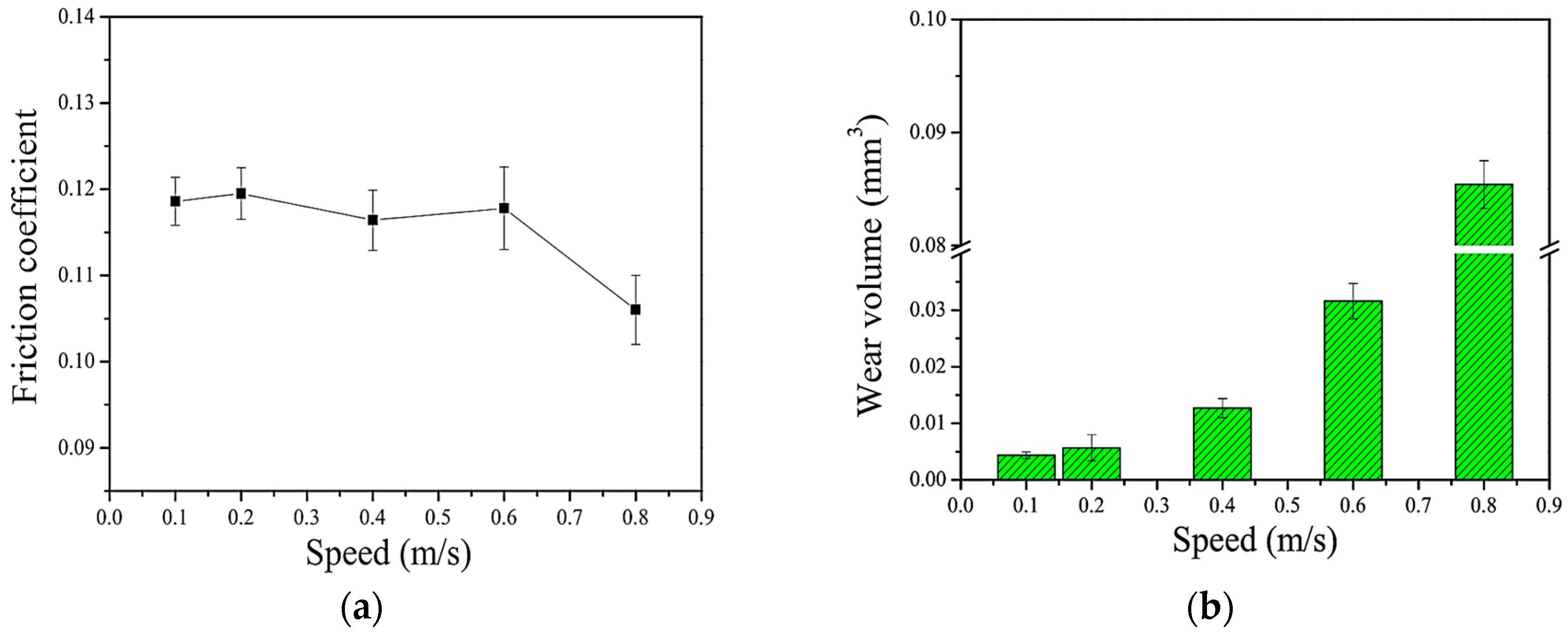
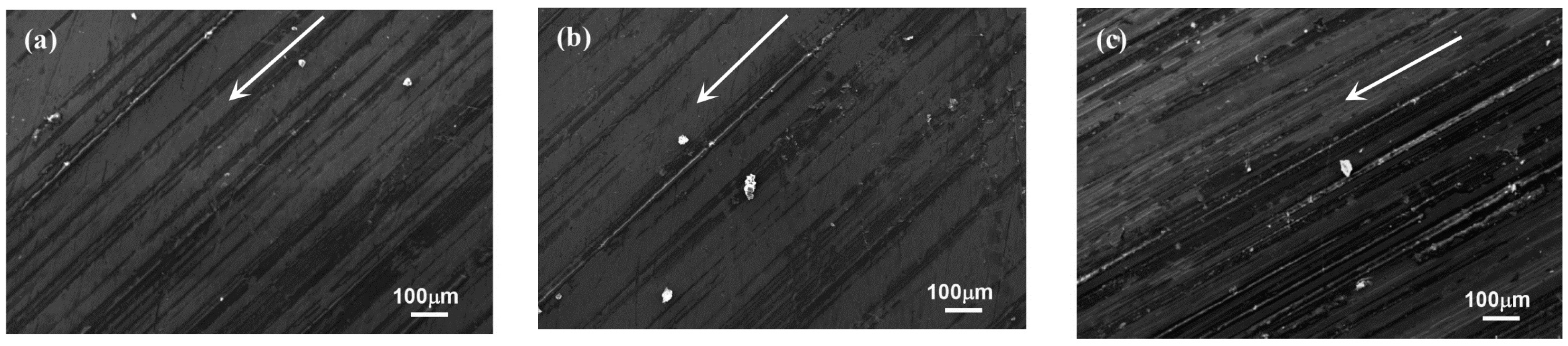
3.1.1. Effect of Sliding Speed

Figure 3 shows the change of friction coefficient and wear at different speeds. It is shown that the friction coefficient decreases with the increase of speed, but wear is the opposite. Figure 4 shows the SEM images of the wear track on the steel disc under different sliding speeds. It can be clearly seen that a thin layer transferred from the PTFE composites to the surface of steel disc. The transfer layer provided shielding of the soft polymer surface from the hard metal asperities, changed the polymer-steel friction into the polymer-polymer friction, which played an extremely important role in reducing wear rate [16]. It can be found that with the increase of sliding speed, the transfer layer formed on the steel disc surface expanded, and the adjacent layers gradually connected to form a uniform transfer layer. This is similar to the process of transfer layer formation described by Ye et al. [17]. Figure 5 shows the micro-morphology of the steel surface with the discontinuous transfer layer (Figure 5a). Figure 5b,c is EDS images of the layer area and the layer-free area, respectively. Figure 5b shows the detected elements in area SA1 including F, C, Ni, indicating the area covering with PTFE composites; Figure 5c shows the detected elements in area SA2 including mainly Fe, indicating the area being steel. Actually, it was also found that the transfer layer was easily peeled off from the steel disc, and then the exposed steel surface was re-covered by transfer layer. When this process reached a balanced state, the formation of the transfer layer became stable. Normally, when the sliding speed is higher, the transfer layer is easier to peel off, in other words, the thin transfer layer formed under low speed will be better in reducing wear [16].
Figure 6 shows the height distributions of the transfer layers formed on the steel disc surface under different sliding speeds. The color bars in Figure 6a indicate the layer thicknesses. The corresponding measured thicknesses were plotted in Figure 6b, which showed the transfer layer thickness increased almost linearly with sliding speed.

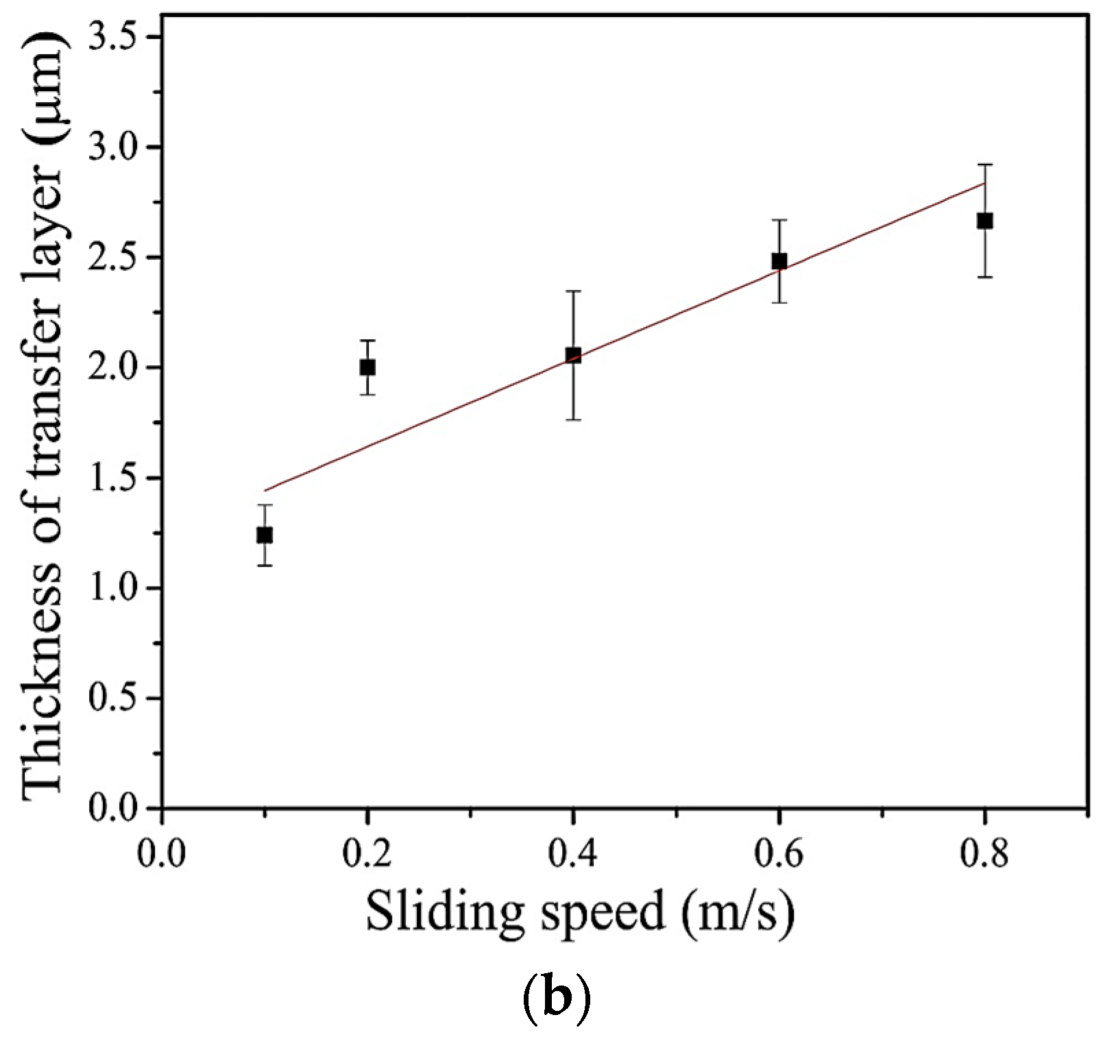
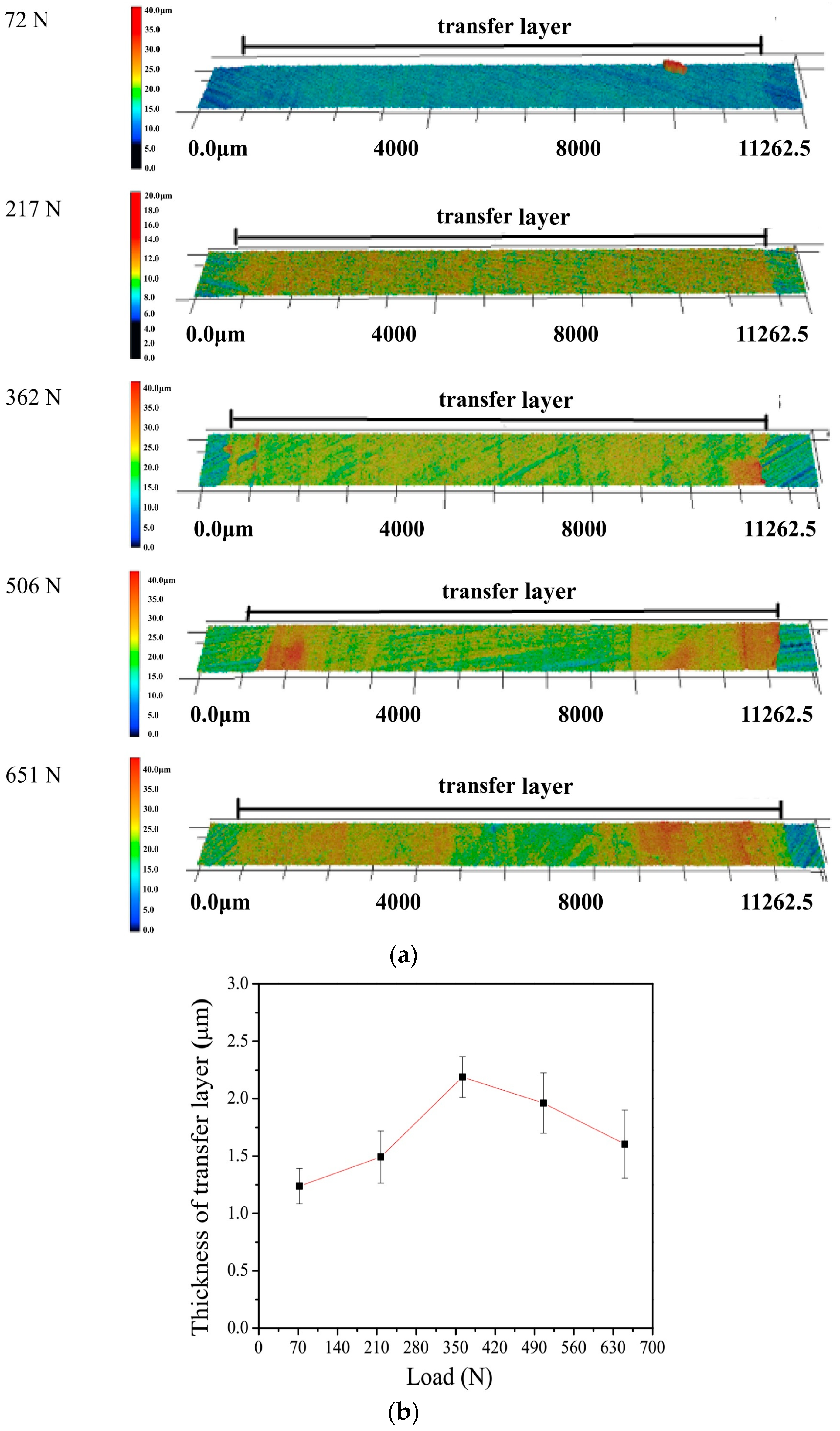
3.1.2. Effect of Load

Figure 7 shows the change of friction coefficient and wear at different loads. It is shown that the friction coefficient decreases with the increase of load, but wear is the opposite. The SEM images of the transfer layers formed on the steel disc under different loads are shown in Figure 8. It can be clearly seen that the PTFE composites were transferred to the steel surface, the transfer layer became more uniform and continuous as the load increased, but the high load may cause damage to the transfer layer (see Figure 8c). In our work, the transfer layer formed at 362 N was uniform and of the best quality (see Figure 8b).
Figure 9 shows the height distributions of the transfer layers formed on the counterface under different loads. From the color changes in the mappings, it is shown that the transfer layer thickness of Ni/PTFE composites increased with the load (see Figure 9a). Figure 9b shows the change of the average transfer layer thickness with load, the curve clearly shows the change: The average transfer layer thickness increased with the load increase at first, reached the maximum at 362 N, and then gradually went down. When the transfer layer thickness exceeded a certain value, the high load will damage the layer and cause the thickness to decrease.

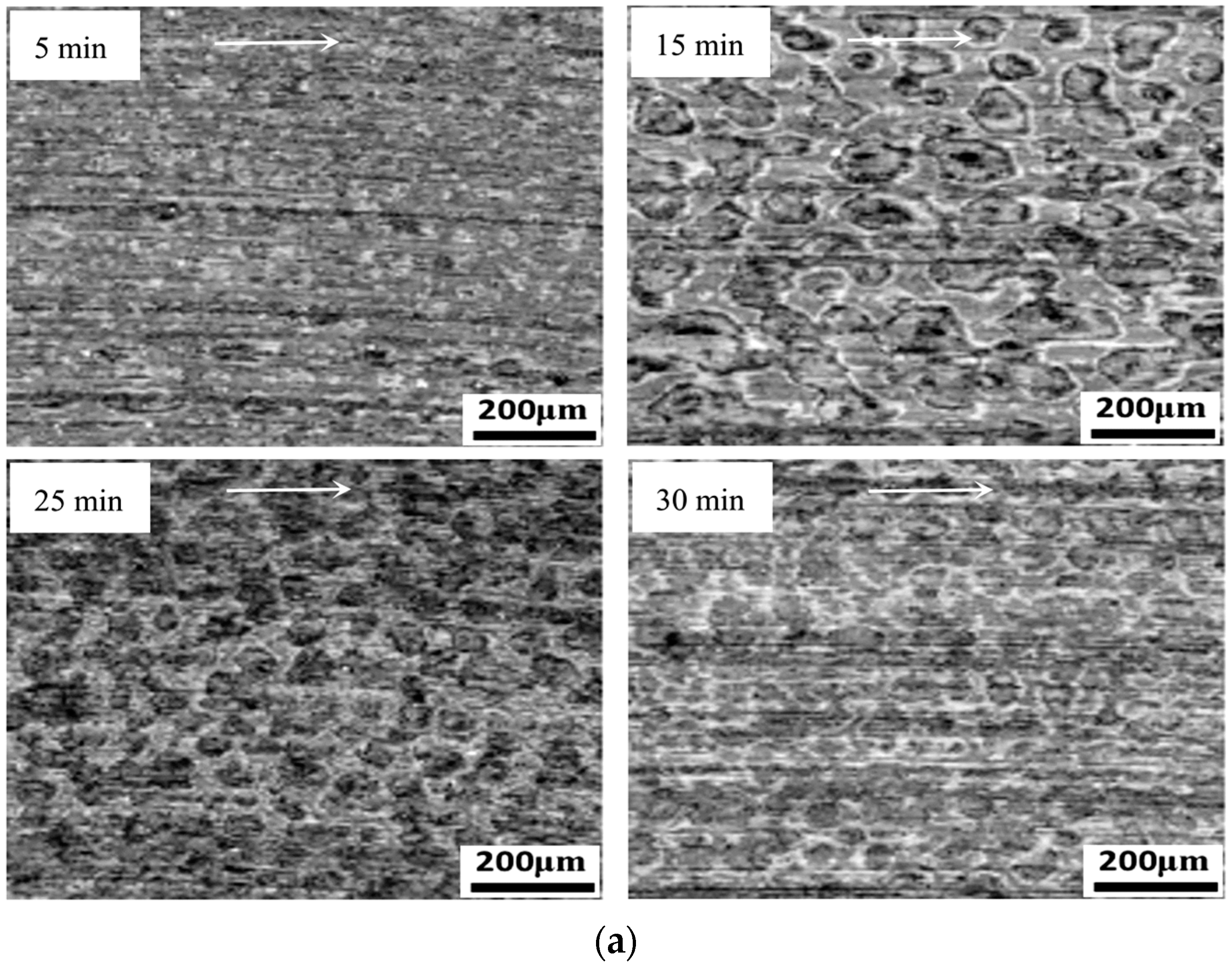
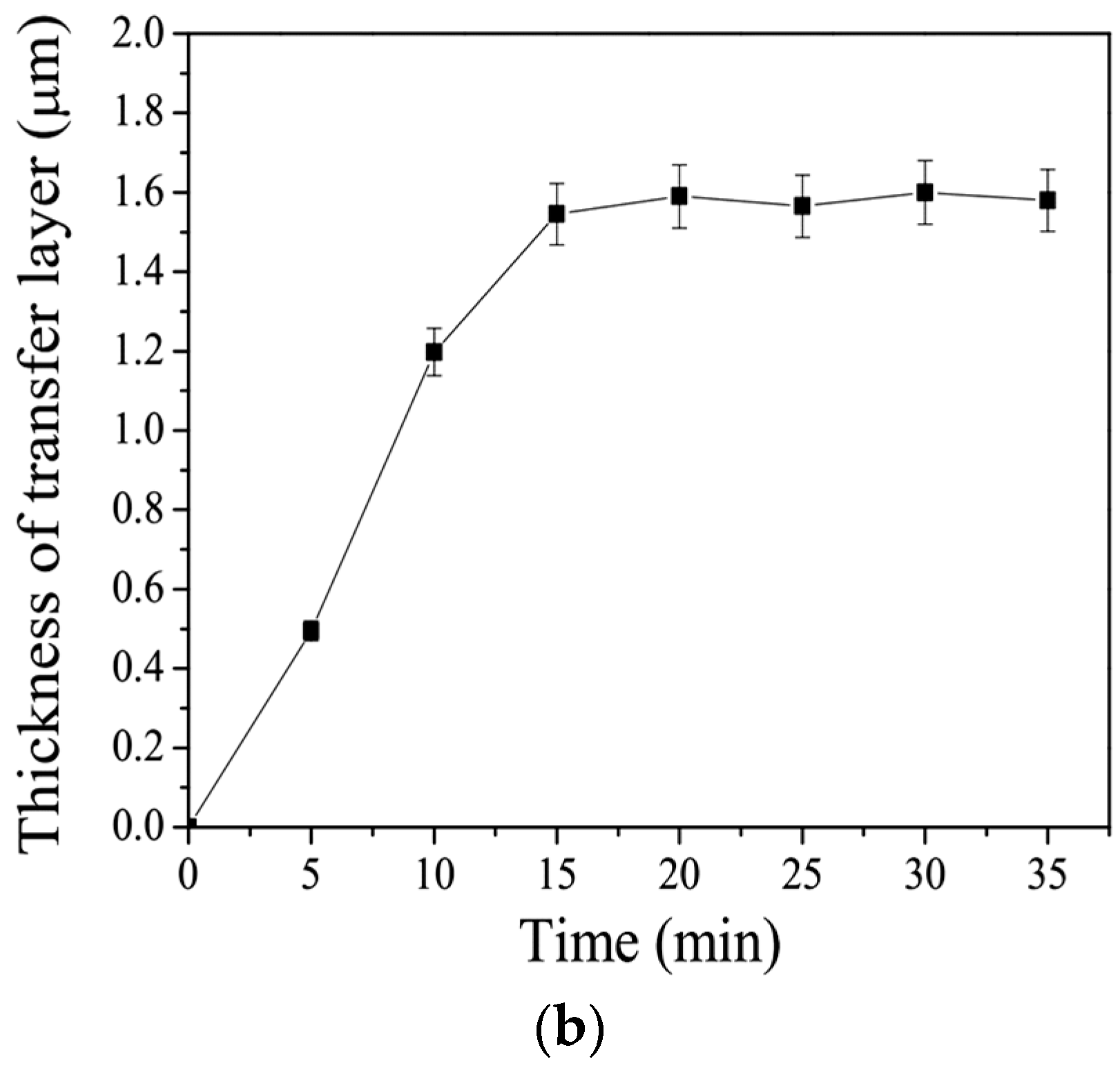
3.1.3. Effect of Wear Time

Figure 10 shows the worn scar surface of the counterface at different times. The following information can be obtained from the optical images (see Figure 10a): At the beginning, the transfer layer gradually begins to form on the steel surface. As the wear test continues, the transfer layer expands laterally and thickens longitudinally; during this period, it will be accompanied by the shedding and repairing of some transfer layers. After a certain period of time, the transfer layer gradually tends to reach a dynamic balance, thus its thickness and coverage will keep in a stable state. In Figure 10a, it can be seen that the degree of grey in the picture is different with bright and dark, which means the transfer layer thickness is nonuniform, i.e., the bright area is thinner, and the dark area is thicker.
The variation curve of the average thickness of the transfer layer over time is shown in Figure 10b. The average thickness of the transfer layer formed on the steel surface increased rapidly in the initial period of friction, then it reached a relatively stable value after about 15 minutes. This is similar to the conclusion in reference [24]. In fact, the variation trend of the thickness of the transfer layer over time is consistent with that the friction enters the steady state through the sliding period [25].

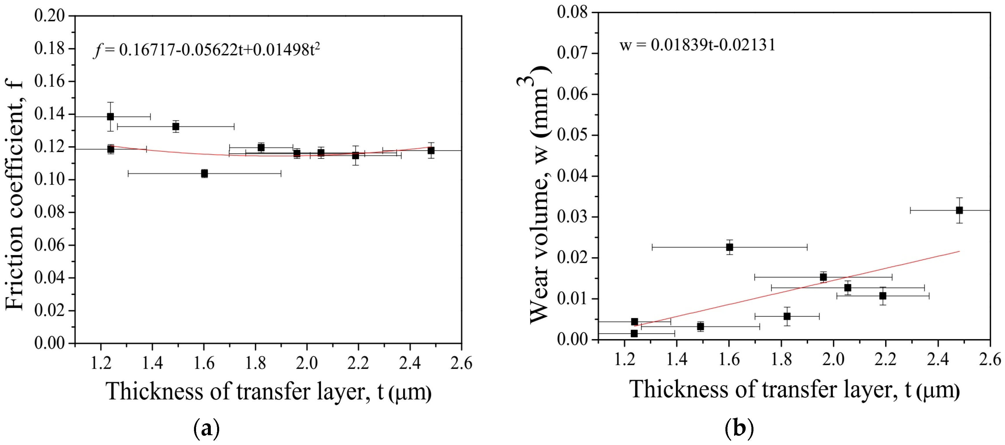
3.2. Relationships between the Transfer Layer Thickness and Friction Coefficient and Wear Volume

Figure 11 shows the relationship between friction coefficient, wear volume and the transfer layer thickness. The data were fitted linearly. We can see from Figure 11a that the friction coefficient negatively correlates with the thickness of the transfer layer, which decreases as the transfer layer thickness increases. The corresponding polynomial fitting is shown in Figure 11a.
The transfer layer reached a steady state, and almost completely covered the surface of the steel disc, isolated the polymer from the steel more effectively, and prevented the polymer composite from being ploughed. Therefore, the friction coefficient became smaller with the increased thickness. Figure 11b shows the wear volume of Ni/PTFE composites increases with the increase in thickness of the transfer layer. The corresponding linear fitting is shown in Figure 11b.
It is easy to understand that when the transfer layer thickness increases, the wear of polymer composites will inevitably increase, because the transfer materials come from the polymer composites. Furthermore, the thicker the transfer layer is, the more easily the layer falls off from the counterface and becomes free debris, thus causing higher wear.

4. Conclusions

Based on our results, the following conclusions can be drawn:
  • A layer of transfer layer of Ni/PTFE composite can be formed on the steel counterface during sliding, which will change the polymer-metal contact to polymer-polymer contact and reduce the friction and wear of polymer-metal system.
  • The transfer layer thickness of the Ni/PTFE composite on the counterface increased linearly with the increase of sliding speed. With the increase of load, the transfer layer thickness increased at first and reached a maximum (2.189 μm), and then went down. As the wear test went on, the transfer layer thickness increased rapidly in the initial period of sliding, then it reached a relatively stable value around 1.55 μm after about 15 min.
  • The transfer layer thickness correlates linearly with the friction coefficient and wear volume of the PTFE composites. With the increase of the transfer layer thickness, the friction coefficient decreased, while the wear volume increased.

Author Contributions

Conceptualization and Supervision, T.X.; Sample Preparation and Validation, Y.Q. and A.C.; Investigation, S.F., Y.Q. and A.C.; Data Curation, S.F. and T.X.; Writing—Original Draft Preparation, S.F.; Writing—Review and Editing, T.X. and S.F.

Funding

This research was funded by National Natural Science Foundation of China (No. 51275144).

Acknowledgments

The authors would like to thank S.B. Ma and M. Tian for their technical supports in sample preparation, and J.X. Ye for his advice in analysis, and K.H. Hu in Hefei University for his technical support in surface measurements.

Conflicts of Interest

The authors declare no conflict of interest.

References

  1. Presuel-Moreno, F.; Jakab, M.A.; Tailleart, N.; Goldman, M.; Scully, J.R. Corrosion-resistant metallic coatings. Mater. Today 2008, 11, 14–23. [Google Scholar] [CrossRef]
  2. Gray, J.E.; Luan, B. Protective coatings on magnesium and its alloys: A critical review. J. Alloy. Compd. 2002, 336, 88–113. [Google Scholar]
  3. Tao, H.; Tsai, M.T.; Chen, H.W.; Huang, J.C.; Duh, J.G. Improving high-temperature tribological characteristics on nanocomposite CrAlSiN coating by Mo doping. Surf. Coat. Technol. 2018, 349, 752–756. [Google Scholar] [CrossRef]
  4. Wang, Y.; Gu, Z.P.; Yuan, N.Y.; Chu, F.Q.; Cheng, G.G.; Ding, J.N. A tri-layer thin film containing graphene oxide to protect zinc substrates from wear. Mater. Res. Express 2018, 5, 8. [Google Scholar] [CrossRef]
  5. Lisjak, D.; Begard, M.; Bruehl, M.; Bobzin, K.; Hujanen, A.; Lintunen, P.; Bolelli, G.; Lusvarghi, L.; Ovtar, S.; Drofenik, M. Hexaferrite/polyester composite coatings for electromagnetic-wave absorbers. J. Therm. Spray Technol. 2011, 20, 638–644. [Google Scholar] [CrossRef]
  6. Levitina, E.I.; Tatarinova, T.S.; Chekmarev, V.M.; Chernevskaya, E.G. Metal-dielectric light-absorbing coatings. Sov. J. Opt. Technol. 1985, 52, 166–168. [Google Scholar]
  7. Paul, S. Surface Coatings: Science and Technology, 2nd ed.; Wiley & Sons, Inc.: New York, NY, USA, 1996. [Google Scholar]
  8. Marrion, A. The Chemistry and Physics of Coatings, 2nd ed.; The Royal Society of Chemistry: Cambridge, UK, 2004. [Google Scholar]
  9. Tracton, A.A. Coatings Materials and Surface Coatings, 3rd ed.; CRC Press: Boca Raton, FL, USA, 2006. [Google Scholar]
  10. Zaitsev, A.L. Investigation of HDPE wear debris formed by friction against metal surfaces with different oxide film content. Wear 1997, 210, 96–103. [Google Scholar] [CrossRef]
  11. Zhou, W.; Zhai, H.X.; Huang, Z.Y.; Guan, M.L. High speed friction characteristics and frictional oxidation of titanium aluminum carbide. J. Chin. Ceram. Soc. 2006, 34, 524–526. (In Chinese) [Google Scholar]
  12. Li, X.; Dai, Z.; Liu, D.; Liu, G.; Xue, T.; Jiang, C.A. A discussion on oxidation of metals under tribological conditions. J. Nanjing Univ. Aeronaut. Astronaut. 1999, 31, 204–208. (In Chinese) [Google Scholar]
  13. Rogov, V.E.; Tsyrenova, G.D.; Cherskii, I.N. Tribosynthesis of lead fluoride in friction of fluroplastic lead-containing composites and its effect on wear resistance. J. Frict. Wear 2009, 30, 285–289. [Google Scholar] [CrossRef]
  14. Pooley, C.M.; Tabor, D. Transfer of PTFE and related polymers in a sliding experiment. Nat. Phys. Sci. 1972, 237, 88–90. [Google Scholar] [CrossRef]
  15. Bahadur, S.; Gong, D.; Anderegg, J.W. The role of copper compounds as fillers in transfer film formation and wear of nylon. Wear 1992, 154, 207–223. [Google Scholar] [CrossRef]
  16. Bahadur, S. The development of transfer layers and their role in polymer tribology. Wear 2000, 245, 92–99. [Google Scholar] [CrossRef]
  17. Ye, J.; Khare, H.S.; Burris, D.L. Transfer film evolution and its role in promoting ultra-low wear of a PTFE nanocomposite. Wear 2013, 297, 1095–1102. [Google Scholar] [CrossRef]
  18. Ye, J.; Burris, D.L.; Xie, T. A review of transfer films and their role in ultra-low-wear sliding of polymers. Lubricants 2016, 4, 4. [Google Scholar] [CrossRef]
  19. Harris, K.L.; Pitenis, A.A.; Sawyer, W.G.; Krick, B.A.; Blackman, G.S.; Kasprzak, D.J.; Junk, C.P. PTFE tribology and the role of mechanochemistry in the development of protective surface films. Macromolecules 2015, 48, 3739–3745. [Google Scholar] [CrossRef]
  20. Yang, E.L.; Hirvonen, J.P.; Toivanen, R.O. Effect of temperature on the transfer film formation in sliding contact of PTFE with stainless steel. Wear 1991, 146, 367–376. [Google Scholar] [CrossRef]
  21. Friedrich, K.; Flöck, J.; Váradi, K.; Néder, Z. Experimental and numerical evaluation of the mechanical properties of compacted wear debris layers formed between composite and steel surfaces in sliding contact. Wear 2001, 251, 1202–1212. [Google Scholar] [CrossRef]
  22. Bahadur, S.; Sunkara, C. Effect of transfer film structure, composition and bonding on the tribological behavior of polyphenylene sulfide filled with nanoparticles of TiO2, ZnO, CuO and SiC. Wear 2005, 258, 1411–1421. [Google Scholar] [CrossRef]
  23. Wang, Y.X.; Yan, F.Y. Tribological properties of transfer films of PTFE-based composites. Wear 2006, 261, 1359–1366. [Google Scholar] [CrossRef]
  24. Bely, V.A.; Sviridenok, A.I.; Petrokovets, M.I.; Savkin, V.G. Friction and Wear in Polymer-Based Materials; Pergamon Press: Oxford, UK, 1982. [Google Scholar]
  25. Myshkin, N.K.; Petrokovets, M.I.; Kovalev, A.V. Tribology of polymers: Adhesion, friction, wear, and mass-transfer. Tribol. Int. 2005, 38, 910–921. [Google Scholar] [CrossRef]
Figure 1. Schematic diagram of the pin-on-disc tribometer.
Coatings 08 00399 g001
Figure 2. Measuring principle of the transfer layer thickness.
Coatings 08 00399 g002
Figure 3. The change of friction coefficient and wear under different speeds: (a) Friction coefficient vs. speed; (b) wear volume vs. speed.
Coatings 08 00399 g003
Figure 4. SEM images of the transfer layers under different speeds: (a) 0.1 m·s−1; (b) 0.4 m·s−1; (c) 0.8 m·s−1.
Coatings 08 00399 g004
Figure 5. SEM and EDS images of the steel surface with and without transfer layers: (a) Steel surface with the discontinuous transfer layer; (b) EDS image of area SA1; (c) EDS image of area SA2.
Coatings 08 00399 g005
Figure 6. (a) The height distribution mappings of transfer layers formed under different sliding speeds; (b) The average transfer layer thickness vs. sliding speed.
Coatings 08 00399 g006aCoatings 08 00399 g006b
Figure 7. The change of friction coefficient and wear under different loads: (a) Friction coefficient vs. load; (b) wear volume vs. load.
Coatings 08 00399 g007
Figure 8. SEM images of the transfer layers under different loads: (a) 72 N; (b) 362 N; (c) 651 N.
Coatings 08 00399 g008
Figure 9. (a) The height distribution mappings of transfer layers formed under different loads; (b) The average transfer layer thickness vs. load.
Coatings 08 00399 g009
Figure 10. (a) Surface of the counterface at different times; (b) Transfer layer thickness over time.
Coatings 08 00399 g010aCoatings 08 00399 g010b
Figure 11. Relationships between tribological properties and transfer layer thickness: (a) Friction coefficient, (b) wear volume.
Coatings 08 00399 g011

